Validator and Control Board Update Instructions for BC1
|
|
|
- Madeleine Cain
- 5 years ago
- Views:
Transcription
1 Validator and Control Board Update Instructions for BC1 Installation Overview The update kit for the Rowe BC1 enables the changer to interface with a Mars AE/VN 120-volt validator. The validator determines the bill denominations accepted. The control board, OBA system and power supply are replaced. The instructions assume the changer has an empty lamp on the front door. If you have an early model that does not have a lamp, the related steps in the instructions can be skipped. A new lamp can easily be added if needed by drilling a new hole in the front door. The final section of these instructions contains more details. The instructions assume a new 120v Mars AE/VN series validator is being installed. The installation information is intended for experienced personnel familiar with the operation of these components. All of the installation procedures must be reviewed and understood prior to installing the kit. The installation instructions are based upon a machine that has not been modified from the original factory configuration. If the machine has been altered in any way, restore the machine to the original factory configuration prior to beginning the conversion. Kit Revisions This kit has been updated. The control board used with this kit is now similar to the BC100 and SBC2 kits. This kit can interface with validators other than the Mars AE/VN series (Coinco, Ardac, Mars VFM, etc.) but requires three additional components be soldered to the board and a different wiring harness. Contact us for details at (800) Kit Components The kit contains the following parts: New control board assembly yellow silk screening (part #KITBDAC1HOPPER) Jumper harness attached to Conn. 3 Validator harness attached to Conn 4 Mars; Conn. 5 for universal harnesess Validator mounting bezel (part # KITVMB) Validator template (part #PL013) Meter to register total bills inserted (part #MCVMETER-12VDC) Four self-threading Phillips screws 8-32 ½ Installation Instructions titled Validator and Control Board Update Instructions for BC1 Tools Required 1/4, 11/32, and 3/8 long handle nut drivers ¼ short handle nut driver Philips screwdriver Pliers Electric drill, 9/64 and 11/64 drill bit, and safety goggles Electric jigsaw with metal cutting blades Pencil to pointed metal tool (used to scratch paint) Metal file 1
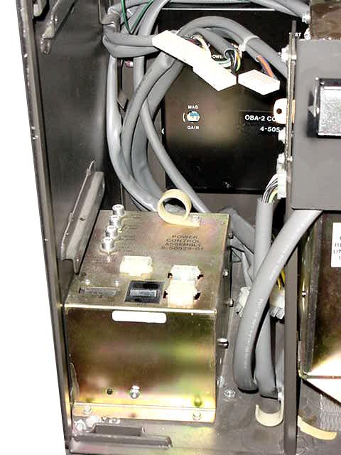
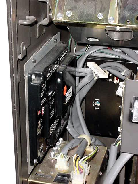
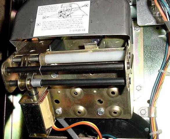
2 Additional Required Items Not Included With Kit Working Mars validator Model AE2411/2451, VN2511, or AE2611 The four hex nuts used to mount the Mars validator to the validator mounting bezel are included in the Mars validator shipping box. Various denominations of bills to test the kit Removal of the Bill Changer s Original Assemblies 1. Remove the hopper from the changer. 2. Depress the payout button on the control board to release the coins in the escrow bucket. 3. Unplug the power cord from the wall outlet. 4. Unplug all of the harnesses from the Dispenser Control board. ( xx) 5. Remove the metal plate assembly that holds the control board by unscrewing the four ¼ screws that secure it to the left wall of the changer. 6. Unplug the three harnesses from the Power Control Assembly ( ); J701, J702, and J Remove the Power Control Center. It is held in place with two ¼ hex screws at the bottom front of the assembly. Once the two screws have been removed, the assembly can be removed by sliding it towards the front of the changer. 8. Unplug the three harnesses connecting to the OBA control box ( ) mounted on the rear of the changer. 9. Remove the OBA control box by unscrewing the three ¼ hex screws at the top of the box and lifting it upwards. 10. Cut all of the cable ties that bundle the various wiring harnesses together. 11. Unplug the harness that connects the OBA acceptor and stacker. 12. Unscrew the two 3/8 bolts that secure the Coin Dispenser Assembly ( ), tilt unit forward. Slide the assembly to the left and forward so it is no longer resting on the side pivot rods. Leave the wiring harness attached to the unit. 13. Remove the Coin Dispenser Assembly with its wiring harness from the changer and set the assembly on a workbench. 14. The wiring harness connected to the Coin Dispenser Assembly divides into two sections. The section with the two 3-position male plugs (purple/orange, yellow/brown, and green/yellow wires) is no longer used. The three wires can be cut at the 9-position connector, or the entire harness bundled together and secured out of the way. 15. Remove all of the loose harnessing in the changer. The only wiring harness in the machine will have a 3-position male plug and a 2-position straight plug. This remaining harness is used with the new control board. The 2-position connector is for the empty bulb. 16. Modify the Coin Dispenser Assembly for direct coin payout per the below instructions. Modification of the assembly involves removing the bucket solenoid assembly. The upgrade kit does not hold any coins in escrow, so the flap connected to the bucket solenoid is removed. 2
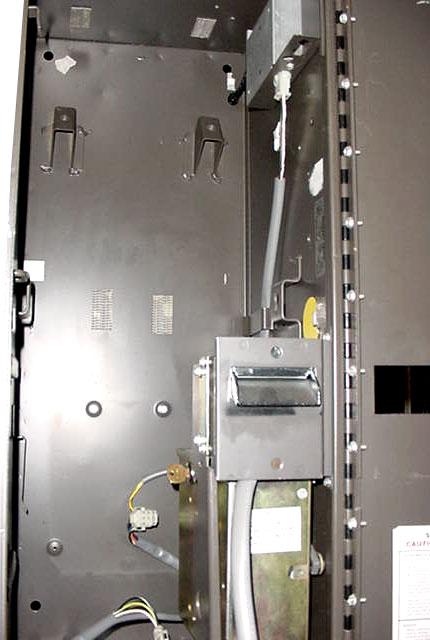
3 Flap Removal Instructions 1. There are three black rods on the rear of the bucket assembly. Remove the e-clip on either side of the assembly from each of the two rods that have e-clips on the outside of the assembly. Push the rods in the direction of the remaining e-clips. The springs and spacers will fall out. The two shafts, springs and spacers are no longer needed. 2. In order to remove the plunger arm and flap assembly, the lower rear black shaft needs to be temporarily removed. Remove one of the e-clips, (inside assembly), and slide the black rod in the direction of the e-clip that was not removed. The flap/plunger will fall out. Slide the rod back into place and secure the e-clip. The modification is complete. 3. Reinstall the Coin Dispenser Assembly with the remaining section of the wiring harness feeding down from the rear. Secure the assembly by tightening both 3/8 bolts. 4. Reinstall the coin hopper. The hopper must have coins to verify the operation of the kit. Removal of OBA Components 1. Remove the OBA acceptor by removing the two ¼ screws that attach it to the right wall, and the two ¼ screws, securing it to the black support bracket. 2. Remove the stacker assembly by removing the two ¼ screws, securing it to the black support bracket. The two additional screws mounting the unit to the right wall must also be removed. Pull the stacker forward and out of the changer. 3. The black support bracket is now removed by loosening the two 11/32 nuts that are now exposed. On some early models, this bracket was welded to the cabinet. If the bracket was spot welded, it will need to be removed by bending the bracket from left to right continuously until the weld breaks. Installation of New Control Board Assembly The new control board assembly is installed on the back wall of the changer in the same area the OBA box was originally located. The placement is not critical, but should be positioned near the bottom so it is easy to view the L.E.D.s and dollar count meter. The new board is mounted using the four slots in the control board case. 1. Hold the metal board enclosure assembly against the rear wall of the changer and mark the position of the four slots with a pencil. 2. Review the safety procedures supplied by the manufacture of the power drill. 3. Drill the four holes using a 9/64 drill bit. 4. Screw the four self-threading screws from the parts kit into the new holes to thread the metal. 5. Remove the upper two screws. 6. Back the lower two screws out ¼. 7. Slide the metal board enclosure assembly over the lower two screws. 8. Insert and tighten the upper right hand screws. 9. Finish tightening the lower two screws. 10. Using the upper left screw attach the meter by tightening the final screw. 11. Attach the white connector from the dollar count meter to header Dollar of the control board. 3
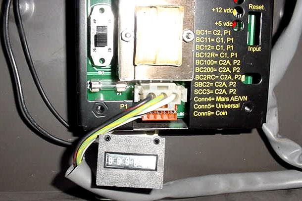
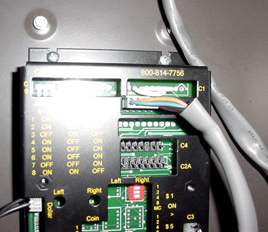
4 Routing the Wiring Harnesses 1. Connect the 7-position straight connector from the Coin Dispenser Assembly to Header C2. 2. Connect the 3-position male connector from the main power box to Header P1. Connect the 2-position straight connector from the empty bulb to Header Empty. The harness that connects to connector Empty on the control board will only have two wires, however the connector has 3 pins. The center pin is ground, and pins 1 and 2 +5vdc. The harness can be attached to either pins 1 and 2 or 2 and 3. One pin will be left open. 3. The harness from P6 will attach to a 120 volt Mars AE/VN validator. 4. The by-pass jumper on header C3 may be removed after confirming proper operation of the kit. Validator and Control Board Update Instructions for BC1 Mount the Validator The existing hole in the front door is enlarged to the size of an industry standard validator mask. The instructions below are for both downstacker and upstacker validators. Before cutting the changer s door, be sure to review the safety instructions supplied with your drill and jigsaw. Always wear safety goggles while drilling and cutting. Depending upon your preference, the validator mounting hole may be cut with the door attached to the changer or with it removed. If you will be cutting the hole with the door attached, it is helpful to close the door of the changer. The door can be removed by unscrewing the 15 screws that secure it to the hinge. 1. Use the hole for the original OBA as a reference point for enlarging the hole for mounting the validator. Place the sticker template so that the top of the existing hole aligns with the top of the template. Be sure to orient the label properly for either a downstacker or an upstacker installation. 2. The larger validator mounting hole in the front door of the changer is now cut. Place the drilling template on the front door of the changer. 3. Drill the four stud holes per the markings on the drilling label. Remove the label. 4. Insert the metal validator mounting bezel so the 4 studs go through the new holes. Once the bezel is flush against the front door use a pointed tool to scratch the paint along the inside border of the bezel. A pencil could also be used. This is the area that will be cut using the jigsaw. 5. Use your jigsaw with high quality metal blades to cut out the new hole. Begin at the right hand side using the existing hole from the OBA acceptor as the guide. 6. Clean up the metal shavings. If there are rough edges around the newly cut area they should be removed using a file. 7. Set the dip switches on the validator per the guide that is silk screened onto the top left corner of the board enclosure. The settings are also listed below. 8. Secure the validator to the changer s door using the validator mounting bracket. The four hex nuts are supplied in the box with the Mars validator. A short 12 harness will be attached to the validator. Remove this harness, as it is not used with the kit. 9. Attach the harness from Header C4 for the control board to the validator. Be sure to observe the position of the two key pins. 4
5 Programming Information When the board is shipped it will be set to dispense four coins for each dollar value inserted. Dip switch 3 will be ON. Do not make any changes until proper operation of the new kit has been confirmed. The payout is programmed by selecting how many coins will be paid out for each dollar value. 1 coin is dispensed when On 2 coins are dispensed when On 4 coins are dispensed when On 8 coins are dispensed when On Dip Switch Settings AE2400 $1-$5 AE2600 $1-$20 VN2500 $1-$5 1. ON 1. ON 1. ON 2. ON 2. ON 2. ON 3. OFF 3. ON 3. OFF 4. ON 4. OFF 4. ON 5. ON 5. OFF 5. ON 6. ON 6. OFF 6. ON 7. OFF 7. OFF 7. ON 8. ON 8. ON 8. OFF Final Setup and Testing At this point, the kit can be tested. Plug the changer back into the wall outlet. The kit should have power. The red L.E.D. indicating +5vdc and the yellow L.E.D. indicating +12vdc will be illuminating. If not, check the ON/OFF switch on the new control board. The green arrows on the validator will begin blinking after a 10 second warm up period. The incandescent count bulb will NOT be lit. Insert bills and test the kit. Once a bill is verified, the incandescent count bulb will illuminate and the hopper motor will begin running. Installation Instructions for Hopper Low Coins Screw (Rowe BC1, SBC2/4, and BC100 Changers) Upon verifying the kit and changer are working properly, a low coins screw can be installed. The low coins screw must be installed to prevent shortchanging a customer. If the changer is in an attended location and the hopper will not empty, it is not necessary to install the low coins screws. The by-pass jumper is installed on header C3 when the kits are shipped. The screw is used to detect ground through the coins in the hopper. When the coins are not touching the screw and metal wall of the hopper, the changer will no longer accept bills. The reset button on the control board must be depressed after the hopper has been filled to reset the board. 5
6 Installation Instructions 1. Turn off the changer. 2. Remove the hopper form the changer and set it in a work area. If it is filled with coins, remove the coins. 3. Drill an 11/64 hole in the black plastic area at the bottom of the hopper. The hole should be located at the center of the hopper and 7/8 from the very bottom of the plastic. Positioning is important so that a coin does not get wedged between the screw and the hopper body. 4. Insert the screw through the hole. Reach your hand into the hopper and align the nut. Begin tightening the screw while holding the nut. When the nut is almost fully tightened, slip the open fork terminal under the screw head. Finish tightening the screw so the harness is held securely in place. 5. Loosen one of the ¼ hex screws on the lower section of the hopper. Place the remaining fork terminal under the screw and tighten the screw. 6. Place the hopper back in the changer. 7. Run the harness over the control board. Unplug the by-pass Jumper at C3 and attach the new harness. 8. Secure the harness neatly in the changer using the tie mounts supplied in the parts kit. 9. Refill the hopper with coins so the screw is covered. 10. Turn on the changer. After a 10-second warm-up period, the validator will accept bills. 11. Place the label on hopper that warns service personnel not to remove hopper without removing the empty sensor wire. TROUBLESHOOTING TIPS The status LED on the control board will display the following codes: 1 Blink Hopper is empty or has no continuity from harness to control board 2 Blinks Time out feature; the maximum allowed time of 20 seconds between coin counts was exceeded 3 Blinks Over payment of coins 4 Blinks The incandescent count bulb is bad or is covered the counting collector (across from emitter) may be bad. The lamp will not illuminate until the change making cycle begins. 5 Blinks The control board s dip switches are not set, thus no payout is possible If the +5vdc LED on the board is not lit check the following: 1. Wall outlet has power and the machines power cord is in excellent condition. 2. The on/off switch on the power input line is in the on position. 3. Unplug the machine and confirm that fuse #1 on the control board is good. It is a 2 amp fuse; 20mm. The input button on the control board can be used to simulate pulses from a dollar bill validator to test the board. This button must be pressed rapidly. It must be pressed once, twice, five, ten, or twenty times as the board will shut down if an impossible dollar value is entered. The pulses must be inputted quickly. If the board shuts down depress the reset button. 6
7 OVERVIEW The green hopper LED lights while the hopper is running The meter clicks once per dollar value at the end of the vend cycle The new control board does not continuously supply power to the incandescent bulb used to count the coins. This helps to extend the life of the bulb. Once a bill has been accepted, the bulb will illuminate and the hopper will begin to payout coins. If the bulb fails, the board will shut down and the status LED will blink 4 times. The reset button on the board will need to be depressed after the bulb is replaced. The harness that connects to Header Empty on the control board will only have two wires, however the connector has 3 pins. The center pin is ground, and pins 1 and 2 +5vdc. The harness can be attached to either pins 1 and 2 or 2 and 3. One pin will be left open. The input and reset buttons are located to the right of the voltage LEDS. When depressing a button a non-conductive slim tool should be used. Technical Assistance Prior to calling please confirm the dip switches on the validator match the required settings. This is our most frequent phone call. Technical Assistance for kit part number KITRBDBC1-MAEVN is available from 9:00am 4:00pm EST at (800) Revision


8 BC1 Figure 1 Figure 2 Figure 3 Figure 4 Figure 5 8 Figure 6


9 BC1 Figure 7 Figure 8 Figure 9 Figure 10 Figure 11 9 Figure 12


10 BC1 Figure 13 Figure 14 Figure 15 Figure 16 Figure Figure 18

11 BC1 Figure 19 11


12 Bullet Bulb for Rowe Changers This custom part replaces the 755 incandescent count emitter bulb in Rowe dollar bill changers. This part is installed in the coin dispenser assembly that is located behind the hoppers. This new part offers the advantage of a considerably longer life and will not fail due to vibrations. This is very important as Rowe changers shut down when the count emitter bulb fails. This item easily pays for it self by eliminating service calls and unnecessary downtime. The Bullet Bulb can be installed in a bill changer that originally used an incandescent lamp BC2RC, SCC3, BC9, C10, BC11, BC115, BC12, BC12R, BC20, BC25, BC25MC, and BC35. Part# NRBULLETBULB $9.95 For Rowe changer models BC100, BC150, BC200, BC1200, BC1400, BC2800, and BC3500. Part # NRBULBxx00 $9.95 Installation: On location installation time of 5 minutes or less. Tools Required: Regular screwdriver, 3/8 socket or pliers to remove the 2 bolts securing the coin dispenser assembly. 12
GENESIS KIT for Rowe. INSTALLATION: BC12R, 1400 Special tools needed drill and a 5/32 bit
 Page 1 of 5 GENESIS KIT for Rowe INSTALLATION: BC12R, 1400 Special tools needed drill and a 5/32 bit THE COIN DETECTOR LIGHT(S) ON THE COIN DISPENSER FRAME NEED TO BE THE NEWER RED LED TYPE. IF YOU HAVE
LGT-306L / LB Club Car Precedent LED Light Bar Bumper Kit Installation Instructions
 LGT-306L / LB Club Car Precedent LED Light Bar Bumper Kit Installation Instructions Caution: Please read through the instructions carefully. Before starting this project, remove the system s positive and
TOYOTA TUNDRA HANDS FREE BLU LOGIC Preparation
 TOYOTA TUNDRA 2008- HANDS FREE BLU LOGIC Preparation Part #: PT923-00111 Conflicts: JBL Audio NOTE: Part number of this accessory may not be the same as the part number shown. Kit Contents: For kits manufactured
Ford Mustang V6 OEM-Style Fog Light Kit Parts List: Quantity: Tool List:
 2015-2017 Ford Mustang V6 OEM-Style Fog Light Kit Parts List: Quantity: Tool List: LED Foglights/ Bezels 2 Flat head & Phillips screwdriver (if you ordered part#3600) Ratchet & Socket set OR Wiring harness
Alliance Towel Dispensing System. Operation Manual
 Alliance Towel Dispensing System Operation Manual Alliance Towel Dispensing System Table of Contents Safety Information... page 2 Mounting Instructions... page 3 Towel Loading Instructions... page 7 Settings...
Cybex Arc Trainer Owner s & Service Manual. 7 - Service
 7 - Service Table of Contents......... iii Warnings/Cautions All warnings and cautions listed in this chapter are as follows:! WARNING: All maintenance activities shall be performed by qualified personnel.
CM1000C CM1800C ChangeMakers. Operator s Manual. Seaga Manufacturing, Inc. 700 Seaga Drive Freeport, IL USA
 CM1000C CM1800C ChangeMakers Operator s Manual Seaga Manufacturing, Inc. 700 Seaga Drive Freeport, IL USA 61032 www.seagamfg.com INTRODUCTION Congratulations on the purchase of your new ChangeMaker. This
General Applicability Note: Recommended Tools. Personal & Vehicle Protection Safety Goggles Seat Covers Floor Covers Special Tools. Installation Tools
 TOYOTA HIGHLANDER/HIGHLANDER HV 2008- Preparation Part #: PT923-00111 Conflicts: JBL Audio, Factory Navigation NOTE: Part number of this accessory may not be the same as the part number shown. Kit Contents:
PARTS LIST. REPLACEMENT PARTS and ACCESSORIES PREPARATION VN1600. PREPARATION VN1500D and VN800B
 INSTALLATION AND OWNER S MANUAL Light Bar N925 for Installation to: Kawasaki VN1500D&E and VN800B Pages 1,2,3 and 5 Kawasaki VN1600 Pages 1, 4 and 5 PARTS LIST QTY. PART NO. DESCRIPTION 1 N925 Light Bar
GENUINE PARTS INSTALLATION INSTRUCTIONS
 GENUINE PARTS INSTALLATION INSTRUCTIONS 1. 2. 3. 4. DESCRIPTION: Accent light Kit APPLICATION: R42H (2011) PART NUMBER: 999F3 AW000 - Universal Accent Lighting Kit. KIT CONTENTS: Item QTY Description Service
To Purchase This Item, Visit BMI Gaming
 Table of Contents General Operation. 3 How Slam-A-Winner plays How the Wheel Scores How the Ball Lift works Programming Options... 4-6 Troubleshooting Guide. 7-8 Parts Identification 9 Schematics 10-13
TOYOTA CAMRY HANDS FREE BLU LOGIC Preparation
 TOYOTA CAMRY 2008- HANDS FREE BLU LOGIC Preparation Part #: PT923-00111 Conflicts: JBL Audio, Factory Navigation NOTE: Part number of this accessory may not be the same as the part number shown. Kit Contents:
Conflicts: JBL Audio, Factory Navigation, Accessory XM Satellite Radio, and Accessory Sirius Satellite Radio
 TOYOTA YARIS SEDAN 2008- HANDS FREE BLU LOGIC Preparation Part #: PT923-00111 NOTE: Part number of this accessory may not be the same as the part number shown. Conflicts: JBL Audio, Factory Navigation,
TOYOTA VENZA HANDS FREE BLU LOGIC Preparation
 TOYOTA VENZA 2009- HANDS FREE BLU LOGIC Preparation Part #: PT923-00111 Conflicts: JBL Audio NOTE: Part number of this accessory may not be the same as the part number shown. Kit Contents: For kits manufactured
ROUSH Active IO Exhaust. Installation Instructions P/N: (R LITE) Fastback GT Convertible GT V8
 Fastback GT Convertible GT V8") Installation Instructions P/N: 422128 (R1318-5231LITE) Fastback GT Convertible GT V8 39555 Schoolcraft Rd, Plymouth MI, 48170 800.59.ROUSH ROUSH Active IO Exhaust Installation Instructions P/N: 422128
Installation Instructions P/N: 422128 (R1318-5231LITE) Fastback GT Convertible GT V8 39555 Schoolcraft Rd, Plymouth MI, 48170 800.59.ROUSH ROUSH Active IO Exhaust Installation Instructions P/N: 422128
TOYOTA tc HANDS FREE BLU LOGIC Preparation
 TOYOTA tc 2011- HANDS FREE BLU LOGIC Preparation Part #: PT923-00111 Conflicts: JBL Audio, Factory Navigation NOTE: Part number of this accessory may not be the same as the part number shown. Kit Contents:
PART NUMBER: H630SXC001. Kit Contents: A. Amplifier with Bracket (1) D. Badge (2) with push nuts (4)
 D. Badge (2) with push nuts (4)") Kit Contents: A. Amplifier with Bracket (1) D. Badge (2) with push nuts (4) E. Clip B. Interface / Power Harness (1) C. Cable tie (8) F. Mounting Nuts (2) G. Replacement Front Speaker (2) H. Badge mounting
Kit Contents: A. Amplifier with Bracket (1) D. Badge (2) with push nuts (4) E. Clip B. Interface / Power Harness (1) C. Cable tie (8) F. Mounting Nuts (2) G. Replacement Front Speaker (2) H. Badge mounting
PONTIAC FIREBIRD
 1974-78 PONTIAC FIREBIRD Two Panel Sequential LED Tail Light Kit Installation Guide Kit Contents: 2 LED panels 2 LED panel mount kits 6 rubber grommets 1 power wire 1 pigtail harness Kit 1 crimp terminal
Optimal Series. Automatic Transfer Switch. Installation and User Manual for the OPT2225 Automatic Transfer Switch. Full Version
 Optimal Series Automatic Transfer Switch Installation and User Manual for the OPT2225 Automatic Transfer Switch Full Version File: OPT2225 Rev2.5.doc November, 2004 2 Thank You For Purchasing This DynaGen
INSTALLATION INSTRUCTIONS
 INSTALLATION INSTRUCTIONS Accessory BACKUP S Application 2012 ODYSSEY Publications No. AII 46724 Issue Date SEP 2011 PARTS LIST Backup Sensor Attachment Kit P/N 08V67-TK8-100A Right center sensor clip
RANGER 900 POWER STEERING KIT
 RANGER 900 POWER STEERING KIT P/N 2880083 APPLICATION MY14 AND NEWER RANGER XP 900 MODELS IMPORTANT It is strongly recommended that this kit be installed by an authorized Polaris dealer. NOTE Use of this
SCION XB HANDS FREE BLU LOGIC Preparation
 SCION XB 2008- HANDS FREE BLU LOGIC Preparation Part #: PT923-00111 Conflicts: JBL Audio NOTE: Part number of this accessory may not be the same as the part number shown. Kit Contents: For kits manufactured
Ebling Back Blade Snow Plow Wireless Controller Kit Only sold by SnowplowsPlus.com and ControlAllWireless.com
 Ebling Back Blade Snow Plow Wireless Controller Kit Only sold by SnowplowsPlus.com and ControlAllWireless.com WARNING Always unplug the plow or shut off the battery breaker when in transport or not in
Flow Sensor Deflector Deflector
 Parts List of Combine Kit Note: Indented items indicate parts included Quantity by Model in an assembly listed above Early Models* 9 9 9 4 5 6 0 0 0 Part Name/Description Part No. 0 0 0 Instruction Kit
Installation of Raxiom Switchback Turn Signal Conversion Kit w/resistors
 Installation of Raxiom Switchback Turn Signal Conversion Kit w/resistors Overview: Below are the steps involved in the installation of the Raxiom Switchback Turn Signal LED lights in the 1987 1993 Ford
TOYOTA im INTERIOR LIGHT KIT Preparation
 Preparation Part Number: PT922-12170 Kit Contents Item # Quantity Reqd. Description 1 1 Main Wire Harness 2 1 Switch 3 1 Switch Header 4 1 ECU 5 1 ECU Bracket 6 1 Hardware Kit 7 1 Instruction Card 8 1
LGT-312L E-Z-Go TXT Light Bar Bumper Kit Installation Instructions
 LGT-312L E-Z-Go TXT 2014+ Light Bar Bumper Kit Installation Instructions Caution: Please read through the instructions carefully. Before starting this project, remove the system s positive and negative
Solstice Electric Fryers SE Series Service Manual
 Solstice Electric Fryers SE Series Service Manual L22-330 R1 (10/12) Notice In the event of problems or questions about your order, contact the Pitco Frialator factory at (603) 225-6684. In the event of
General Applicability: KIA Sorento. Issues Current Kit does not allow for CAN DATA remote access
 Document #730135 Created ACH 08/02/2018 Revised ACH 08/20/18 A2 General Applicability: 2018-19 KIA Sorento Issues Current Kit does not allow for CAN DATA remote access Kit Contents: Item# Component Description
Wolverine Turn Signal / Horn Kit 2102
 All years Yamaha Wolverine STOP - THIS KIT IS DESIGNED SPECIFICALLY FOR ALL YEAR AND MODELS YAMAHA WOLVERINE. IF YOUR MACHINE IS NOT ONE OF THESE MODELS DO NOT PROCEED. Contact Ryco Motorsports or your
JEEVES. JEEVES Installation Manual. Installation Manual The Easiest Do-It-Yourself Dumbwaiter on the Market
 1 888-323-8755 www.nwlifts.com JEEVES Installation Manual The Easiest Do-It-Yourself Dumbwaiter on the Market This manual will cover the installation procedure step-by-step. The installation of this dumbwaiter
Replacing the Gear Drive Motor Assembly and GFCI Module for Operation with the Chain Drive Motor Assembly
 Replacing the Gear Drive Motor Assembly and GFCI Module for Operation with the Chain Drive Motor Assembly Kit Contents B00009035-3 Motor Drive Assembly (Return original to CMI) B00007698-8 GFCI Module
GENUINE PARTS INSTALLATION INSTRUCTIONS
 GENUINE PARTS INSTALLATION INSTRUCTIONS DESCRIPTION: APPLICATION: PART NUMBER: Electronic Tailgate Lock Kit Nissan Titan 999M2-W3005 KIT CONTENTS: Item Qty. Part Description Service Part Number A 1 Electronic
Installation Instructions for John Deere cotton picker models: 9986 & 2-row and All-row systems included.
 Ag Leader Technology Cotton Picker Installation Installation Instructions for John Deere cotton picker models: 9986 & 9996 2-row and All-row systems included. IMPORTANT: Ensure the model numbers shown
GENUINE PARTS INSTALLATION INSTRUCTIONS
 GENUINE PARTS INSTALLATION INSTRUCTIONS 1. 2. 3. 4. DESCRIPTION: Accent light Kit APPLICATION: Infiniti JX (2013) PART NUMBER: 999F3 YY000 - Universal Accent Lighting Kit. KIT CONTENTS: Item QTY Description
Service & Maintenance
 Service & Maintenance Amplifier Monitor LEDs & Tubes (Wall-Rock-PV) Translucent Panel (Wall-Rock-PV) Glass Panel (Rock-Star) Fans & Filter G2-1 External Peavey Amplifier) Amplifier Removal 1. Disconnect
Installation Instructions for Key Switch SNOWRATOR
 2017 Installation Instructions for Key Switch SNOWRATOR We appreciate your purchase of L.T. Rich s Product. Please read carefully before Operating or detaching. AES L.T.RICH 6/15/2017 SHIPPING CONTENTS...
PART NUMBER: H630SSJ000. Kit Contents: A. Amplifier with Bracket (1) D. Badge (2) with push nuts (4)
 D. Badge (2) with push nuts (4)") Kit Contents: A. Amplifier with Bracket (1) D. Badge (2) with push nuts (4) E. Clip B. Harness (1) C. Cable tie (8) F. Mounting Hardware (2) G. Replacement Speaker (2) H. HVAC Duct extension (2) IMPORTANT:
Kit Contents: A. Amplifier with Bracket (1) D. Badge (2) with push nuts (4) E. Clip B. Harness (1) C. Cable tie (8) F. Mounting Hardware (2) G. Replacement Speaker (2) H. HVAC Duct extension (2) IMPORTANT:
igen2500 and ipro2500 IGNITION COIL RETROFIT GUIDE
 igen2500 and ipro2500 IGNITION COIL RETROFIT GUIDE This comprehensive retrofit guide is for replacing the ignition coil on Westinghouse s igen2500 and ipro2500 inverter generators. The purpose of this
SCION TC HANDS FREE BLU LOGIC Preparation
 SCION TC 2008- HANDS FREE BLU LOGIC Preparation Part #: PT923-00099 Conflicts: JBL Audio NOTE: Part number of this accessory may not be the same as the part number shown. Kit Contents: For kits manufactured
PD15-UL-M KIT INSTRUCTIONS
 PD5-UL-M KIT INSTRUCTIONS The Command Access PD5-UL-M-KIT is a field-installable motorized latchpullback kit for the Jackson 85/95 & AHT 8/9 series devices. A. B. C. D. E. F. G. H. I. KIT INCLUDES TOOLS
INSTALLATION INSTRUCTIONS
 Rear Vision System Aftermarket and Factory 5.0, 8.4 and 6.1 MyGig Touch Screen Display (Factory Display requires Chrysler/Dodge dealer to activate) 2009 Current* Dodge Ram (Kit part number 1009-6503) *NOTE:
TOYOTA TACOMA HANDS FREE BLU LOGIC Preparation. Item 5 Item 6 Item 7 Item 8. Item 4. General Applicability Note: Recommended Tools
 TOYOTA TACOMA 2008- HANDS FREE BLU LOGIC Preparation Part #: PT923-00098 Conflicts: JBL Audio, Factory Navigation Kit Contents: NOTE: Part number of this accessory may not be the same as the part number
LGT-311L Bumper LED Light Kit EZ-Go RXV Installation Instructions
 LGT-311L Bumper LED Light Kit EZ-Go RXV Installation Instructions Caution: Please read through the instructions carefully. Before starting this project, remove the system s positive and negative connections
Adjustable Light Kits E-Z-Go TXT All Models Installation Instructions
 Adjustable Light Kits E-Z-Go TXT All Models 1996-2013 Installation Instructions Caution: Please read through the instructions carefully. Before starting this project, remove the system s positive and negative
INSTALLATION INSTRUCTIONS
 INSTALLATION INSTRUCTIONS Accessory Application Publications No. All 12035 SYSTEM 2012 RIDGELINE Issue Date NOV 2011 PARTS LIST Security System Attachment Kit: P/N 08E55-SJC-101 Flange bolt Unit bracket
Detroit Speed, Inc. Electric Headlight Door Kit Corvette P/N: &
 Detroit Speed, Inc. Electric Headlight Door Kit 1968-82 Corvette P/N: 122006 & 122007 The Detroit Speed Inc. Electric Headlight Door Kit replaces the stock vacuum actuated system on all 1968-82 Corvettes.
2015 Mustang Lightbar (All Models) CDC#
 CDC#") 2015 Mustang Lightbar (All Models) CDC# 1511-7000-01 Components: 1 CDC Lightbar Note: READ instructions before starting installation!!! CDC Part# Driver side bracket 0511-6001-05 Passenger side bracket
2015 Mustang Lightbar (All Models) CDC# 1511-7000-01 Components: 1 CDC Lightbar Note: READ instructions before starting installation!!! CDC Part# Driver side bracket 0511-6001-05 Passenger side bracket
Installation Instruction
 T F W 604.549.9379 604.549.9555 fluxwerx.com Installation Instruction DRIVER ENCLOSURE Ceiling Type Version Grid Battery Pack GRID MOUNT INSTALL OPTIONS OPTION 1: Standard Vertical Grid drivers can be
ONBOARD AIR HOOKUP KIT
 ONBOARD AIR HOOKUP KIT PART NO. 20052 (30 amp - 110PSI on, 150PSI off) PART NO. 20053 (30 amp - 85PSI on, 105 PSI off) PART NO. 20055 (30 amp - 90 PSI on, 120 PSI off) IMPORTANT: It is essential that you
VALICHANGER OPERATIONS MANUAL SERIES AC1000/1001
 Fax:(954)917-5204 VALICHANGER OPERATIONS MANUAL SERIES AC1000/1001 Table of Contents SECT. A: SET-UP & INSTALLATION Uncrating & Setup 3 Mounting instructions 3-4 Filling the Hopper 4 Using the Dump Mode
SCION XB HANDS FREE BLU LOGIC Preparation. Item 4 Item 5 Item 6 Item 7. General Applicability. Note: Recommended Tools
 SCION XB 2008- HANDS FREE BLU LOGIC Preparation Part #: PT923-00090 Conflicts: JBL Audio NOTE: Part number of this accessory may not be the same as the part number shown. Kit Contents: Item 1 Item 2 Item
YARIS 4-DOOR 2007 INTERIOR LIGHT UPGRADE
 Document # 3999 4/26/06 4-DOOR 2007 INTERIOR LIGHT UPGRADE Preparation Part Number: 00016-52060 Code: IL1 Kit Contents Item # Quantity Reqd. Description 1 1 12 Light Guide 2 1 7 Light Guide 3 1 Hardware
ONE TOUCH CONTROL BOX
 ONE TOUCH CONTROL BOX CONVERSION KIT INSTRUCTIONS REMOVAL, INSTALLATION, OPERATION, AND REMOTE CONTROL PROGRAMMING THUNDERSTONE PART #101322 REVISION A JULY 14 TH 2016 2 P a g e INSTALLING THE THUNDER
Digitrip Retrofit System for ITE K-3000, K-3000 S, K-4000 and K-4000 S Breakers
 Supersedes IL 33-858-4 Dated 05/02 Digitrip Retrofit System for ITE K-3000, K-3000 S, K-4000 and K-4000 S Breakers Digitrip Retrofit System for ITE K-3000, Digitrip Retrofit System for ITE K-3000, K-3000
INSTALLATION INSTRUCTIONS
 INSTALLATION INSTRUCTIONS Accessory Application Publications No. SYSTEM 2005 ACCORD All 27511 (DX, LX) 2-AND 4-DOOR Issue Date AUG 2004 PARTS LIST Security System Attachment (LX): P/N 08E55-SDA-100A Unit
Service Manual Mozart Fireplace
 Service Manual Mozart Fireplace Model Numbers: CFP3913 REV PCN DATE 00 11637 Sep 23, 09 Dimplex North America Limited 1367 Industrial Road Cambridge ON Canada N1R 7G8 1-888-346-7539 www.dimplex.com In
***THE OWNER'S MANUAL MUST BE GIVEN TO THE END USE CUSTOMER AFTER COMPLETING THE INSTALLATION.***
 INSTALLATION INSTRUCTIONS FOR THE MOTOR TRIKE HARLEY MECHANICAL REVERSE 1999-2006 FIVE SPEED FLH LAST UPDATED: OCTOBER 2011 AS THE INSTALLER OF THIS MECHANICAL REVERSE, YOU MUST BECOME FAMILIAR WITH PROPER
Maintenance Guide AZTEC BNF-2000 BILL ACCEPTOR PRIMARY COMPONENT PARTS
 AZTEC BNF-2000 Bill Acceptor Maintenance Guide October, 2007 October, 2007 Maintenance Guide JCM is a registered trademark of JCM American Corporation. All other product names mentioned herein may be registered
GENUINE PARTS INSTALLATION INSTRUCTIONS
 GENUINE PARTS INSTALLATION INSTRUCTIONS 1. DESCRIPTION: 2. APPLICATION: 3. PART NUMBER(S) REQUIRED FOR INSTALLATION: 4. KIT CONTENTS: Item Qty. Fog Lamp Kit Titan MY16 999F1 W4000 Fog Lamp Kit Part Description
GENUINE PARTS INSTALLATION INSTRUCTIONS
 GENUINE PARTS INSTALLATION INSTRUCTIONS 1. 2. 3. 4. DESCRIPTION: APPLICATION: PART NUMBER: KIT CONTENTS: Accent light Kit Pathfinder 999F3 XZ000 - Accent Lighting Kit. Item QTY Description Service Part
INSTALLATION INSTRUCTIONS
 INSTALLATION INSTRUCTIONS Accessory Application 2008 ACCORD 2-DOOR Publications No. AII 37561-38377 Issue Date NOV 2007 PARTS LIST Control unit bracket (L4) Back-up Sensor Attachment Kit P/N 08V67-TE0-100A
Table of Contents. Timer Identification Timer ID BLU-U Features: 1K 6K BLU-U Features 1K 6K
 DUSA Pharmaceuticals, Inc. Table of Contents Go to Chart # Timer Identification Timer ID BLU-U Features: 1K 6K BLU-U Features 1K 6K BLU-U Features: 10K BLU-U Features 10K BLU-U Symptom Fans Running, Timer
Installation Instructions
 Installation Instructions For PTI STEZA C (2x2 Burner Configuration) & PTI STEZB C (3x1 Burner Configuration) Revision E Safe-T-Element Installation Instructions Table of Contents 1. PREPARATION..3 1.1
SCION xd INTERIOR LIGHTING UPGRADE Preparation
 Preparation Part Number: PTS21-52085 Light Guide Kit Contents Item # Quantity Reqd. Description 1 1 Controller Board, 4 color programmed w/ Bracket 2 1 RGB, LED Engine wire harness 3 2 14mm Light Rod,
THIS GUIDE IS INTENDED FOR DEALERS AND SOLAR COMFORT TECHNICIANS ONLY AND IS NOT MEANT OR INTENDED TO BE REPRODUCED OR DISTRIBUTED TO THE CONSUMER
 THIS GUIDE IS INTENDED FOR DEALERS AND SOLAR COMFORT TECHNICIANS ONLY AND IS NOT MEANT OR INTENDED TO BE REPRODUCED OR DISTRIBUTED TO THE CONSUMER Table of Contents Page Tools Needed (A) 3 Replacement
The steering column is of a modular construction and features easy to service electrical switches.
 file://c:\tso\tsocache\vdtom_5368\svk~us~en~file=svkb4a01.htm~gen~ref.htm Page 1 of 3 Section 11-04A: Steering Column, Ranger DESCRIPTION AND OPERATION 1997 Ranger Workshop Manual Steering Column NOTE:
GENUINE PARTS INSTALLATION INSTRUCTIONS
 GENUINE PARTS INSTALLATION INSTRUCTIONS 1. 2. 3. 4. DESCRIPTION: APPLICATION: PART NUMBER: KIT CONTENTS: Accent light Kit Versa Note 999F3 4Z000 - Accent Lighting Kit. 999Q9 AY000 - Accessory Service Connector
GIVE ME A BRAKE Light Kit 2005 / 2006 MINI Cooper/Cooper S Brake Light Modification
 Page 1 of 6 GIVE ME A BRAKE Light Kit 2005 / 2006 MINI Cooper/Cooper S Brake Light Modification ****Pages 1 and 2 apply only to non-convertible MINI s**** ****for convertibles please go to page 5**** This
3.5-4 GENERIC POSITIVE AIR SHUTOFF
 3 October 2016 1036732 1036733 Generic Positive Air Shutoff (I-00189) 1 DOWNLOAD ENHANCED INSTALL MANUALS AT dieselperformance.com 3.5-4 GENERIC POSITIVE AIR SHUTOFF P/N# 1036732 P/N# 1036732-M P/N# 1036733
72 Mustang Mach 1 tachometer cluster and gauge conversion
 72 Mustang Mach 1 tachometer cluster and gauge conversion Dated: 02-17-2009 (drafted by a Chevy person working on his first Ford -not good-) Revised: 11-05-2010 The following information pertains to how
PRODUCT INFORMATION BULLETIN #3365 DIGITAL MOTOR CONTROL PLATTER SYSTEMS For Serial Number and After
 PRODUCT INFORMATION BULLETIN #3365 DIGITAL MOTOR CONTROL PLATTER SYSTEMS For Serial Number 28640996 and After Record Platter System Identification Numbers Here: Model # Serial # Table of Contents Program
DEFINITIONS OF SAFETY TERMS DANGER indicates an imminent hazard. If you fail to avoid this hazard, it WILL cause death or serious injury.
 CRUIS N EXOTICA S E C T I O N THREE Service SAFETY INSTRUCTIONS The following safety instructions apply to operators and service personnel. Read these instructions before servicing or preparing the Video
INSTALLATION INSTRUCTIONS
 1. Note: It is recommended this install be done with a minimal amount of fuel in the tank. This will reduce fuel spills and make installation easier and safer. Draining the tank is recommended. INSTALLATION
Upgrade v3 to v3.2. SeeMeCNC Guides. Upgrade v3 to v3.2. Rostock Max v3 Uprgade to v3.2. Written By: SeeMeCNC seemecnc.dozuki.
 SeeMeCNC Guides Upgrade v3 to v3.2 Rostock Max v3 Uprgade to v3.2 Written By: SeeMeCNC 2018 seemecnc.dozuki.com/ Page 1 of 34 INTRODUCTION This guide is intended to Upgrade a Rostock Max v3 to a Rostock
Do not have any open flame or heat sources close to the installation
 March 6, 2017 IS# 791 Page 1 of 16 Thank you for purchasing a Transfer Flow, Inc. 50-gallon replacement fuel system for your 2011-16 Ford diesel short bed pickup. This system will fit any 2x4 or 4x4 crew
Safe-T-element Installation Instructions
 Safe-T-element Installation Instructions For: PTI STEZA (2x2 Burner Configuration) & PTI STEZB (3x1 Burner Configuration) Revision K (May. 3 2012) TABLE OF CONTENTS 1. PREPARATION... 3 1.1 General Safety
GMC Duramax (LBZ) High Idle Kit Note: Only for automatic transmissions with cruise control
 High Idle Kit Note: Only for automatic transmissions with cruise control") U 17 December 2014 (1036606) 2006-07 GMC Duramax (LBZ) High Idle Kit (I-00318) 1 GMC Duramax (LBZ) High Idle Kit Note: Only for automatic transmissions with cruise control 1036606 2006-2007 GMC Duramax
U 17 December 2014 (1036606) 2006-07 GMC Duramax (LBZ) High Idle Kit (I-00318) 1 GMC Duramax (LBZ) High Idle Kit Note: Only for automatic transmissions with cruise control 1036606 2006-2007 GMC Duramax
3 in 1 TRAIL CHARGER with LOCKOUT
 Owner s Manual P/N: 283821 500 3 in 1 TRAIL CHARGER with LOCKOUT 283821 01 Version 2.04 07/05/2011 Owners Manual Operation Installation Wiring Diagram Troubleshooting Parts Breakdown 1 GENERAL OPERATION
= Experienced
 I N S T A L L A T I O N G U I D E APPLICATION LENGTH MODEL YR PART # Ford F-250 / F-350 / F-450 Regular Cab * (48 ) 2002-2003, 2008-2012 75134-01A Ford F-250 / F-350 / F-450 Super Cab * (60 ) 2002-2003,
2-row and All-row systems included.
 Ag Leader Technology Cotton Picker Installation Installation Instructions for John Deere cotton picker models: 2-row and All-row systems included. IMPORTANT: Ensure the model numbers shown above correspond
Optima ETF-600/ETF-610
 Optima ETF-600/ETF-610 4B ETF-610 1C 4A 5 6 7 7 6 ETF-600 1A 1C PARTS LIST ETF-600 AND ETF-610 FAUCETS Item No. Code No. Part No. Description 1A. 065086 ETF-54-A Faucet and Sensor Assembly (ETF-600). 065117
GENUINE PARTS INSTALLATION INSTRUCTIONS
 GENUINE PARTS INSTALLATION INSTRUCTIONS 1. 2. 3. DESCRIPTION: APPLICATION: PART NUMBER: Accent light Kit Cube (MY2013+) 999F3 AW000 - Universal Accent Lighting Kit. 4. KIT CONTENTS: Item QTY Description
GENUINE PARTS INSTALLATION INSTRUCTIONS
 GENUINE PARTS INSTALLATION INSTRUCTIONS 1. 2. 3. 4. DESCRIPTION: APPLICATION: PART NUMBER: KIT CONTENTS: Security light Kit Maxima 999F4 AX009 - Universal Security Lighting Kit. Item QTY Description Service
6500DC Dual Motor Wireless Controller Kits
 6500DC Dual Motor Wireless Controller Kits READ ALL DIRECTIONS FIRST BEFORE PROCEEDING NOTE: SEE THE QUICK PROGRAM INSTRUCTIONS BEFORE OPERATING THE FIRST TIME. DO NOT REMOVE THE TRANSMITTER BATTERY Please
GENUINE PARTS INSTALLATION INSTRUCTIONS
 GENUINE PARTS INSTALLATION INSTRUCTIONS 1. 2. 3. 4. DESCRIPTION: Accent light Kit APPLICATION: Versa (2012) PART NUMBER: 999F3 AW008 - Universal Accent Lighting Kit. KIT CONTENTS: Item QTY Description
ELECTRICAL SYSTEM UPGRADE
 NEW CONTROLLER & ELECTRICAL SYSTEM UPGRADE FOR DAIRY TECH, INCORPORATED 10, 30 & 60G PASTEURIZERS Parts to Include 2 Wire ties (Nuts) 2 sticky wire mount pads Large Rubber Grommet (for bottom of electric
INSTALLATION INSTRUCTIONS
 INSTALLATION INSTRUCTIONS Accessory Application Publication No. WINCH MOUNT P/N 08L74-HR3-A20 After 13 TRX420 (All except TRX420FA/FPA) After 13 TRX500 (All except TRX500FA/FPA) MII 15067 Issue Date Revised:
INSTALLATION AND CUSTOMER CARE INFORMATION 80 SERIES & 90 SERIES TREATMENT STATIONS
 INSTALLATION AND CUSTOMER CARE INFORMATION 80 SERIES & 90 SERIES TREATMENT STATIONS Customer Service and Technical Support: 8:00 AM to 5:00 PM central (M-Th) 8:00 AM to 4:30 PM central (Fri) Phone: 800-257-7407
PFadvantage JD 3300/4400/6600/7700; 4420
 Ag Leader Technology Combine Installation JD 33//66/77; 2 Note: Indented items indicate parts included Quantity by Model in an assembly listed above Early Late Part Name/Description Part Number 3 3 6 6
Vibrator Kit. Stainless Steel & Poly Hopper Spreaders with FLEET FLEX Electrical System
 October 1, 2016 Lit. No. 95098, Rev. 01 PARTS LIST Vibrator Kit Stainless Steel & Poly Hopper Spreaders with FLEET FLEX Electrical System 5 7 6 9 8 4 1 10 2 3 99504 1 Vibrator Kit Item Part Qty Description
COMPONENT WORK SAMPLE 8 Simulated Assembly MAINTENANCE MANUAL. From 1974 to March 15, 2003
 COMPONENT WORK SAMPLE 8 Simulated Assembly MAINTENANCE MANUAL From 1974 to March 15, 2003 Copyright 2008 VALPAR International Corporation P.O. Box 5767 Tucson, Arizona 85703-5767 All rights reserved. No
DVL Cypress Face Installation Instructions (SKU )
") Table of Contents Compatibility... 1 Packing List... 1 Installation... 2 Prepare the Insert for Face Installation... 2 Assemble the Face... 6 Attach the Surround Panels (if applicable) and Face... 10 Hang
Table of Contents Compatibility... 1 Packing List... 1 Installation... 2 Prepare the Insert for Face Installation... 2 Assemble the Face... 6 Attach the Surround Panels (if applicable) and Face... 10 Hang
INSTALLATION MANUAL. For: ACURA NSX
 INSTALLATION MANUAL For: ACURA NSX Package contents cable loom Electronics Bridge plug Installation manual Requested Tools Diagonal pliers small screwdriver T30 Torx Bit 1/4 or 3/8 ratchet 10mm Socket
INSTALLATION INSTRUCTIONS
 INSTALLATION INSTRUCTIONS [1] Description: Tow Hitch Wire Harness Kit [2] Application: Nissan Rogue Note: Tow Harness application is limited to specific vehicle option packages that include tow harness
401B/1KDB CoolRite/FreezeRite Installation Manual I003
 401B/1KDB CoolRite/FreezeRite Installation Manual 99-16105-I003 Copyright 2011 by ALL rights reserved. Information in this document is subject to change without notice. Companies, names and data used in
GENUINE PARTS INSTALLATION INSTRUCTIONS
 GENUINE PARTS INSTALLATION INSTRUCTIONS 1. 2. 3. 4. DESCRIPTION: Security Light Kit APPLICATION: Altima Sedan (2013+) PART NUMBER: 999F4 AX010 - Universal Security Lighting Kit. KIT CONTENTS: Item QTY
INSTALLATION INSTRUCTIONS
 INSTALLATION INSTRUCTIONS Accessory Application Publications No. SYSTEM ACCORD 2-DOOR (LX/EX L4, LX V6) AII 25749 Issue Date FEB 2004 PARTS LIST Double-sided adhesive tape XM Radio Attachment Kit : P/N
Instructions for 2-row monitoring only
 Installation Instructions for CaseIH cotton picker models: Instructions for 2-row monitoring only CAUTION: Ensure the model numbers shown above correspond to the machine model. If you receive the incorrect
Installation and Operation
 HQ Installation and Operation Copyright 2013 Handi Quilter, Inc. All rights reserved. Printed in the U.S.A. 08/2013 Table of Contents Contents of the HQ HighRise kit 3 Installation 6 Operation of the HQ