Wheel Alignment Basics Explained: Shimmed Control Arms
|
|
|
- Merry Howard
- 6 years ago
- Views:
Transcription

 in this article.")
1 Wheel Alignment Basics Explained: Shimmed Control Arms By Joe Fisher This brief article is not meant to teach someone how to align the front steering/suspension but to explain the three basic specifications that are set during a standard wheel alignment. It was explained to me by an old-timer back when I wasn t an old-timer. This article is not vehicle specific and the basics can apply to all cars. The table at the end of the article can be used for any vehicle that uses shims at the upper control arm. I will not get into four-wheel alignment (e.g., aligning all front and rear wheels on a C2 Corvette) in this article. Toe-In, Toe-out: Toe is a condition where the fronts of the tires are either pointed in toward one another, or pointed away from one another in a horizontal plane measured in a fraction of inches. If your toes are pointed toward each other then that is toe-in, if they are pointed away from each other then it is toe-out. So, if your tires are pointed inward you have a toe-in condition and if pointed outward then you have a toe-out condition. Normally, you want 1/16 to 1/8 toe-in. A misadjusted toe setting will cause rapid tire wear and will sometimes cause tire squeal. If they are severely out of specifications the vehicle can become darty and the tire tread will become feathered.. Top view of wheels Camber: Camber is the tilt of the top of the tire, in a vertical plane toward or away from the engine; it is measured in degrees. If the top of the tire is tilted outward, it is called positive camber, if it is tilted inward, that is negative camber. A poorly adjusted Camber setting will cause the tires to wear on one edge only. If you ever saw a car that has a raised front end, the tire normally goes toward negative camber. 1
, you are determining the caster setting.")

2 Caster: Caster is the most misunderstood part of an alignment. If you draw an imaginary line through the upper and lower ball joint and measure it in degrees (from the vertical), you are determining the caster setting. Some analogies to describe positive and negative caster: Picture a shopping cart s front wheel (below left), the wheel s axle lies behind the pivot and, when you push the cart; the wheel always follows. This is called negative caster. Now, picture a bicycle fork (below right), its wheel axle is in front of the pivot point and, when you ride your bike and take your hands off the handle bars, the wheel tracks straight. It wants to stay forward this is positive caster Now, draw an imaginary line through the pivot point and the axle and imagine the axle is the lower ball joint and the pivot is the upper ball joint. In the case of the shopping cart, the line slopes front to back which is negative caster, and on the bicycle, it goes back to front which is positive caster. If the upper ball joint is directly above the lower, you have zero caster. If the upper ball is more toward the rear of the car than the lower you have positive caster. 2
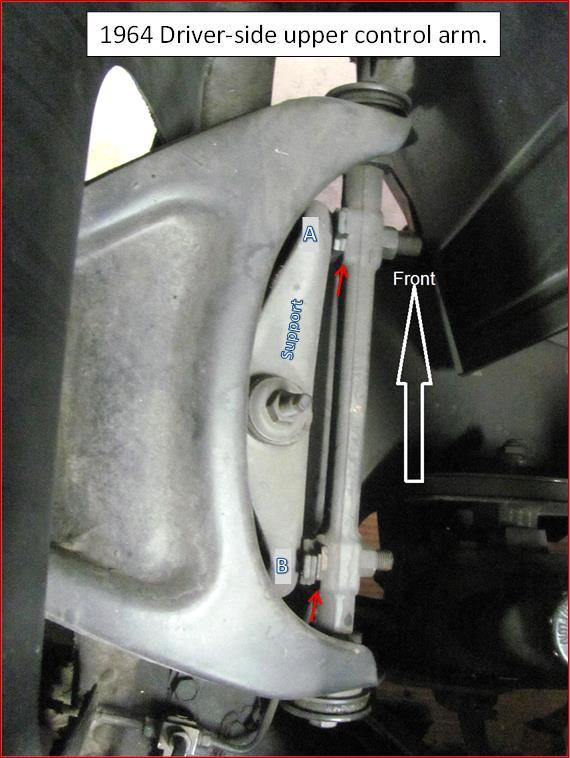
3 Keep in mind that negative caster wants to follow and positive caster wants to track (lead). Thus, the car will pull toward the side that has the lesser amount of positive caster. This is why my mentor always told me to put ½ degree more positive caster on the right side then left to help counteract the crown in the road which wants to pull the car towards the curb. Caster causes the car to pull to one side if all else is set up OK. Also, I had cars with too much negative caster which caused the steering wheel not to center itself after making a turn. Looking at the picture below of the left (driver side) control arm on a 64 Corvette you will notice the upper shaft is on the engine side of the support. On cars with the shaft on the outside of the support these explanations will be reversed. To change the camber without changing the caster you would install or remove equal amounts of shims at A and B from between the shaft and support. Adding shims will move the shaft toward the engine and, therefore, bring the top of the tire inward decreasing the camber and, if you remove shims from the shaft, it moves outward, moving the top of the tire out toward the fender thereby increasing camber. To change the caster you will have to move the upper ball joint either toward the front or the rear of the vehicle. On this set up if you move the front of the shaft toward the engine, i.e., add shims, or move the rear of the shaft away from the engine, i.e., removing shims, you will move the ball joint forward decreasing the caster, going toward negative. Inversely, if you move the front of the shaft away from the engine, remove shims, or move the rear of the shaft toward the engine, add shims, you will move the ball joint rearward increasing the positive caster. The table below shows the correlation between shim changes and resultant changes in the camber/caster setting. Joe Fisher 3
4 4
5 Effect of adding, removing or changing positions of upper control-arm shims on camber and caster setting. Action Camber Change* Caster Change* Adding Shims to: Front only Less Less Rear only Less More Front and Rear, same size Less Same Removing Shims From: Front only More More Rear only More Less Front and Rear, same size More Same Switch Shim From:** Front to Rear Same More Rear to Front Same Less *Less means the reading will move toward the negative and More will move the reading toward the positive. **Taking a shim from one bolt and installing it on the other bolt, not adding or removing any shims. Some suggested wheel alignment specs for C2 Corvettes with radial tires: Corvette Forum post by John Hinckley (John Z): Street specs for radial tires: Front camber: zero Front caster: 2 o -2.5 o positive (with P/S); manual 1.5 o positive Front toe-in: zero-to-1/16" TOTAL toe-in Rear camber: zero-to-1/2 o negative Rear toe-in: 1/16" TOTAL toe-in, split equally across the thrust centerline (1/32" per side). Midyear suspension geometry was designed in 1961 around bias-ply tires; the camber gain doesn't respond well to extremely wide tires. PDF layout by Dave Zuberer (DZVette) 5
ATASA 5 th. Wheel Alignment. Please Read The Summary. ATASA 5 TH Study Guide Chapter 47 Pages: Wheel Alignment 64 Points
 ATASA 5 TH Study Guide Chapter 47 Pages: 1403 1423 64 Points Please Read The Summary Before We Begin Keeping in mind the Career Cluster of Transportation, Distribution & Logistics Ask yourself: What careers
Camber Angle. Wheel Alignment. Camber Split. Caster Angle. Caster and Ride Height. Toe Angle. AUMT Wheel Alignment
 AUMT 1316 - Wheel Alignment 11/15/11 Camber Angle Wheel Alignment Donald Jones Brookhaven College Camber Split Camber is the amount that the centerline of the wheel tilts away from true vertical when viewed
Why do cars need Alignment
 Why do cars need Alignment The main purpose of wheel alignment is to make the tires roll without Scuffing, slipping, or dragging under all operating conditions. Caster Camber Toe Steering axis inclination
GENERAL INFORMATION. Wheel Alignment Theory & Operation
 Fig. 1: Checking Steering Linkage GENERAL INFORMATION Wheel Alignment Theory & Operation ADJUSTMENTS NOTE: This article is intended for general information purposes only. This information may not apply
BASIC WHEEL ALIGNMENT
 BASIC WHEEL ALIGNMENT You have got to know all the angles. Correct wheel alignment plays a huge part in a customer s positive driving experience. Having it dialed in correctly is essential to proper vehicle
How to Set the Alignment on Ford Mustangs
 How to Set the Alignment on 1967-1973 Ford Mustangs Let's Get This Straight - Mustang Monthly Magazine Christopher Campbell Technical Editor March 25, 2015 Frontend alignment is one of the most basic adjustments
Suspension and Steering Alignment
 Suspension and Steering Alignment Matthew Whitten Brookhaven College Alignment Components Ride height Caster Camber Included angle Scrub radius Thrust angle Toe Turning radius Toe out on turns Steering
Wheel Alignment Defined
 Wheel Alignment Defined While it's often referred to simply as an "alignment" or "wheel alignment," it's really complex suspension angles that are being measured and a variety of suspension components
Basic Wheel Alignment Techniques
 Basic Wheel Alignment Techniques MASTERING THE BASICS: Modern steering and suspension systems are great examples of solid geometry at work. Wheel alignment integrates all the factors of steering and suspension
TRUCK AND BUS TYRE I TECHNICAL MANUAL MAINTENANCE AND CARE
 TRUCK AND BUS TYRE I TECHNICAL MANUAL MAINTENANCE AND CARE About tyre inflation Truck alignment and tyre wear Tyre damage TECHNICAL INFORMATION MAINTENANCE AND CARE About tyre inflation ONE OF THE MOST
Fundamentals of Steering Systems ME5670
 Fundamentals of Steering Systems ME5670 Class timing Monday: 14:30 Hrs 16:00 Hrs Thursday: 16:30 Hrs 17:30 Hrs Lecture 3 Thomas Gillespie, Fundamentals of Vehicle Dynamics, SAE, 1992. http://www.me.utexas.edu/~longoria/vsdc/clog.html
Typical mounting of a dial indicator for a radial check. Moog Automotive, Inc.
 Inspect / Service / Test / Replace To find out if the ball joint is loose beyond manufacturer's specifications, use an accurate measuring device. Most load carrying ball joints have a wear limit of 0.060"
Wheel Alignment Fundamentals
 CHAPTER 67 Wheel Alignment Fundamentals OBJECTIVES Upon completion of this chapter, you should be able to: Describe each wheel alignment angle. Tell which alignment angles cause wear or pull. KEY TERMS
2004 SUSPENSION. Wheel Alignment - Corvette. Caster Cross +/ / Fastener Tightening Specifications Specification Application
 2004 SUSPENSION Wheel Alignment - Corvette SPECIFICATIONS WHEEL ALIGNMENT SPECIFICATIONS Wheel Alignment Specifications Camber Cross Caster Cross Suspension Camber Tolerance Caster Tolerance FE1 & FE3
DIAGNOSIS AND TESTING
 DIAGNOSIS AND TESTING SUSPENSION AND STEERING SYSTEM 2007 SUSPENSION Suspension - Nitro CONDITION POSSIBLE CAUSES CORRECTION FRONT END NOISE 1. Loose or worn wheel bearings. 1. Replace wheel bearings.
ALIGNMENT AND ROAD CROWN
 Classification: Reference: Date: ST08-001 NTB08-097 October 9, 2008 ALIGNMENT AND ROAD CROWN APPLIED VEHICLES: All Nissan - except GT-R SERVICE INFORMATION Customers may report that their vehicle pulls
INTRO/APPLICATIONS PARTS TOOLS ACCESSORIES BRAKE & CV SPC GEAR & INDEXES APPLICATIONS PARTS
 TABLE OF CONTENTS INTRO/.................. 2-39 How to Use the Sourcebook......................................2 How to Sell Alignment...........................................2 Training Resources..............................................3
Customer Engagement - Execution Playbook Module 1 WHEEL ALIGNMENTS ALIGNMENTS
 Customer Engagement - Execution Playbook Module 1 WHEEL ALIGNMENTS -------------------------- ALIGNMENTS 101 ------------------------------ While a wheel alignment is often referred to simply as an alignment,
ALIGNING A 2007 CADILLAC CTS-V
 ALIGNING A 2007 CADILLAC CTS-V I ll describe a four-wheel alignment of a 2007 Cadillac CTS-V in this document using homemade alignment tools. I described the tools in a previous document. The alignment
Wheel Alignment And Diagnostic Angles (STE04)
") Module 1 Wheel Alignments Wheel Alignment And Diagnostic Angles (STE04) Wheel Alignments o Conditions Requiring An Alignment o Conditions Requiring An Alignment (cont d) o Why We Do Checks And Alignments
Module 1 Wheel Alignments Wheel Alignment And Diagnostic Angles (STE04) Wheel Alignments o Conditions Requiring An Alignment o Conditions Requiring An Alignment (cont d) o Why We Do Checks And Alignments
SUSPENSION 2-1 SUSPENSION TABLE OF CONTENTS
 XJ SUSPENSION 2-1 SUSPENSION TABLE OF CONTENTS page ALIGNMENT... 1 FRONT SUSPENSION... 7 page REAR SUSPENSION... 16 ALIGNMENT TABLE OF CONTENTS page AND WHEEL ALIGNMENT...1 DIAGNOSIS AND TESTING SUSPENSION
Real Square RSX User Instructions v. 10.2
 Real Square RSX User Instructions v. 10.2 Basic RSX Kit Contents: (1) RSX Shaft Mounted Laser Assembly (2) Axle Alignment Fixtures (Hub Mount or Spindle Thread-on Mount) (2) Wheel Measurement Fixtures
II YEAR AUTOMOBILE ENGINEERING AT AUTOMOTIVE CHASSIS QUESTION BANK UNIT I - LAYOUT, FRAME, FRONT AXLE AND STEERING SYSTEM
 II YEAR AUTOMOBILE ENGINEERING AT 6402 - AUTOMOTIVE CHASSIS QUESTION BANK UNIT I - LAYOUT, FRAME, FRONT AXLE AND STEERING SYSTEM 1. Write about the requirements of frame and selection of cross section
WHEEL ALIGNMENT SPECIFICATIONS & PROCEDURES
 WHEEL ALIGNMENT SPECIFICATIONS & PROCEDURES 1988 Jeep Cherokee 1988 Wheel Alignment INTRODUCTION PRE-ALIGNMENT VEHICLE CHECKS Prior to making wheel alignment adjustments, check and adjust the following
STEERING SYSTEM Introduction
 STEERING SYSTEM Introduction The steering makes it possible to change direction. The steering must be reliable and safe; there must not be too much play in the steering. It must be possible to steer accurately.
Fiat - Argentina - Wheel Aligner / Headlamp Aimer #16435
 2017 Fiat - Argentina - Wheel Aligner / Headlamp Aimer #16435 Wheel Aligner / Headlamp Aimer Operation & Maintenance Manual Overview Fori Automation Version 1.2 4/21/2017 TABLE OF CONTENTS Section 1.0
Global West Suspension 655 South Lincoln Ave San Bernardino Ca Phone Fax Web address globalwest.
 Global West Suspension 655 South Lincoln Ave San Bernardino Ca. 92408 Phone 877-470-2975 Fax 909-890-0703 Web address globalwest.net Mustang coilover instruction sheets for 64-66 Kit includes the following
SUSPENSION 2-1 SUSPENSION CONTENTS
 ZJ SUSPENSION 2-1 SUSPENSION CONTENTS page ALIGNMENT... 1 FRONT SUSPENSION... 6 page REAR SUSPENSION... 14 ALIGNMENT INDEX page GENERAL INFORMATION WHEEL ALIGNMENT... 1 DIAGNOSIS AND TESTING SUSPENSION
SECTION 3A WHEEL ALIGNMENT
 SECTION 3A WHEEL ALIGNMENT NOTICE: All wheel alignment fasteners are important attaching parts in that they could affect the performance of vital components and systems, and/or could result in major repair
SUSPENSION 2-1 SUSPENSION CONTENTS
 DN SUSPENSION 2-1 SUSPENSION CONTENTS page ALIGNMENT... 1 FRONT SUSPENSION... 5 page REAR SUSPENSION... 13 ALIGNMENT INDEX page GENERAL INFORMATION WHEEL ALIGNMENT... 1 DIAGNOSIS AND TESTING PRE-ALIGNMENT
AXLE ALIGNMENT ZF (40 FT)
") SECTION 04-000.10 04-000.10/ 1 2010DE06 GENERAL CONDITIONS See Figures 1 and 2 for the geometry of the frontand rear axles. Figure 3 represents the axis system of a Nova LFS 40-ft bus. Before performing
SECTION 04-000.10 04-000.10/ 1 2010DE06 GENERAL CONDITIONS See Figures 1 and 2 for the geometry of the frontand rear axles. Figure 3 represents the axis system of a Nova LFS 40-ft bus. Before performing
MM Caster/Camber Plates, (MMCC7989)
") 3430 Sacramento Dr., Unit D San Luis Obispo, CA 93401 Telephone: 805/544-8748 Fax: 805/544-8645 www.maximummotorsports.com MM Caster/Camber Plates, 1979-89 (MMCC7989) IMPORTANT: The bearing used in our
3430 Sacramento Dr., Unit D San Luis Obispo, CA 93401 Telephone: 805/544-8748 Fax: 805/544-8645 www.maximummotorsports.com MM Caster/Camber Plates, 1979-89 (MMCC7989) IMPORTANT: The bearing used in our
Unit No.03 Front axle, Steering system, Rear axle, Wheel & Tyres
 Unit No.03 Front axle, Steering system, Rear axle, Wheel & Tyres Prepared by, Prof. Santosh Kailas Chandole ME (Design Engineering) BE (Automobile Engineering) Steering system STEERING REQUIREMNTS: It
GM Muscle Car Upper Control Arms
 GM Muscle Car Upper Control Arms Q1: My SPC upper control arms contact the frame when I lift the vehicle with a jack. What should I do? A1: It is critical that you consider the entire suspension system
Tires with inner tubes were used until the 50s. Inner tube tires
 Tires Back in the day Way back in the day Pneumatic Tires Dunlop patented them for bicycles in 1888 Michelin put them on cars in 1895 Goodyear was started in 1898. Named after the inventor of vulcanized
SUSPENSION 2-1 SUSPENSION CONTENTS
 WJ SUSPENSION 2-1 SUSPENSION CONTENTS page ALIGNMENT... 1 FRONT SUSPENSION... 4 page REAR SUSPENSION... 15 ALIGNMENT INDEX page AND WHEEL ALIGNMENT... 1 SERVICE PROCEDURES PRE-ALIGNMENT... 2 AND WHEEL
Setup Guide and Chassis Tuning Tips (simple version) By Jim Daniels
 By Jim Daniels") This document is released into the public domain and may be reproduced and distributed in its entirety so long as all credit to Jim Daniels remains. If you find this guide helpful please consider donating
This document is released into the public domain and may be reproduced and distributed in its entirety so long as all credit to Jim Daniels remains. If you find this guide helpful please consider donating
SUSPENSION 2-1 SUSPENSION CONTENTS
 TJ SUSPENSION 2-1 SUSPENSION CONTENTS page ALIGNMENT... 1 FRONT SUSPENSION... 5 page REAR SUSPENSION... 12 ALIGNMENT INDEX page GENERAL INFORMATION WHEEL ALIGNMENT... 1 DIAGNOSIS AND TESTING SUSPENSION
SUSPENSION 2-1 SUSPENSION TABLE OF CONTENTS
 DN SUSPENSION 2-1 SUSPENSION TABLE OF CONTENTS page ALIGNMENT... 1 FRONT SUSPENSION - 4x2... 6 page FRONT SUSPENSION - 4x4... 14 REAR SUSPENSION... 23 ALIGNMENT TABLE OF CONTENTS page AND OPERATION WHEEL
SUSPENSION 2-1 SUSPENSION CONTENTS
 TJ SUSPENSION 2-1 SUSPENSION CONTENTS page ALIGNMENT... 1 FRONT SUSPENSION... 6 page REAR SUSPENSION... 13 ALIGNMENT INDEX page DESCRIPTION AND OPERATION WHEEL ALIGNMENT... 1 DIAGNOSIS AND TESTING SUSPENSION
total vehicle alignment
 2 total vehicle alignment A guide created By: TBS Factoring service TBS Factoring Service 2 total vehicle alignment...created by tbs factoring service TBS Factoring Service, LLC is a leading provider of
TRAILING ARM CHEVY PICK-UP
 TRAILING ARM 1947 1954 CHEVY PICK-UP Congrats on choosing the best riding and handling rear suspension for your Chevy. Trailing arm suspension can be tricky to install correctly, so please follow our recommendations,
2011 MKS Workshop Manual. SECTION : Suspension System - General Information DESCRIPTION AND OPERATION Procedure revision date: 05/25/2010
 SECTION 204-00: Suspension System - General Information 2011 MKS Workshop Manual DESCRIPTION AND OPERATION Procedure revision date: 05/25/2010 Wheel Alignment Angles Camber Negative and Positive Camber
Part # GM G Body Tru-Turn Suspension Package
 350 S. St. Charles St. Jasper, In. 47546 Ph. 812.482.2932 Fax 812.634.6632 www.ridetech.com Part # 11329599 78-88 GM G Body Tru-Turn Suspension Package Front Components: 1 11323699 Upper Strong Arms 1
Installation Instructions
 Part # - 6-67 C Front TruTurn System Recommended Tools 6-67 C Front TruTurn System Installation Table of contents Page... Included components Page... Upper Control rm Components Page... Lower Control rm
2010 Prince Edward Island Department of Education and Early Childhood Development P.O. Box 2000, Charlottetown Prince Edward Island Canada, C1A 7N8
 2010 Prince Edward Island Department of Education and Early Childhood Development P.O. Box 2000, Charlottetown Prince Edward Island Canada, C1A 7N8 Tel. (902) 368-4600 Fax. (902) 368-4622 http://www.gov.pe.ca/eecd/
655 South Lincoln Avenue / San Bernardino CA Phone / Fax / Web address: globalwest.net
 655 South Lincoln Avenue / San Bernardino CA. 92408 Phone 877-470-2975 / Fax 909-890-0703 / Web address: globalwest.net Part # TBC-9 or TBC-10 --- 1963-82 Corvette Rear swing arm installation instructions:
C-10 StrongArms
 Part # 11342699(63-70)/11352699(71-72) - C10 StrongArms Recommended Tools 1963-1972 C-10 StrongArms Installation Table of contents Page 2... Included components Page 3... Upper Control Arm Components Page
1. SPECIFICATIONS 2. WHEEL ALIGNMENT
 441101 083 1. SPECIFICATIONS Front Suspension Rear Suspension Description Suspension type Spring type Shock absorber type Stabilizer bar type Suspension type Spring type Shock absorber type Stabilizer
What s in the Box? AMT Motorsport C5/C6 Corvette Steel Frame Camber Kit User s Guide
 AMT Motorsport C5/C6 Corvette Steel Frame Camber Kit User s Guide Thank you for purchasing the AMT Motorsport Camber Kit. We believe this is the most versatile camber kit available on the market, but with
Hub Stands -- VERSION 5.0
 Hub Stands -- VERSION 5.0 Thanks for choosing our Alignment Hub Stands for your chassis setup needs. We hope you'll find them as handy, accurate, and easy to use as we do! Each stand has a max capacity
The WHAT and WHY of. Toe Caster - Camber Kingpin Inclination - Thrust Angle Steering Angle Wheel setback
 The WHAT and WHY of Toe Caster - Camber Kingpin Inclination - Thrust Angle Steering Angle Wheel setback WHEEL ALIGNMENT SIMPLIFIED Wheel alignment is often considered complicated and hard to understand
Tach-Drive Distributor Reconditioning Joe Fisher PDF prepared by Dave Zuberer Link to Thread on the Corvette Forum (C1-C2)
") Tach-Drive Distributor Reconditioning Joe Fisher PDF prepared by Dave Zuberer Link to Thread on the Corvette Forum (C1-C2) I just finished two Corvette tach-drive distributors. One was a 71 small block
Tach-Drive Distributor Reconditioning Joe Fisher PDF prepared by Dave Zuberer Link to Thread on the Corvette Forum (C1-C2) I just finished two Corvette tach-drive distributors. One was a 71 small block
What s in the Box? AMT Motorsport C5/C6 Corvette Steel Frame Camber Kit User s Guide
 AMT Motorsport C5/C6 Corvette Steel Frame Camber Kit User s Guide Thank you for purchasing the AMT Motorsport Camber Kit. We believe this is the most versatile camber kit available on the market, but with
Description: Camber Kit Part Number: A Application: C5, C6 Steel Frame
 Description: Camber Kit Part Number: 450-401009-A Application: 1997-2004 C5, 2005-2013 C6 Steel Frame Tools Needed: 3/8" drive ratchet 24" long 3/8" torque wench 10mm deep socket 13mm socket 13mm deep
Installation Instructions
 Nov 3, 2017 G-Body Rear Coilover Conversion Kit 1 P a g e Installation Instructions The following instructions are intended for professional installers and are guidelines only. Speedtech Performance assumes
HEIDTS SUPERIDE INSTALLATION INSTRUCTIONS OPEN WHEEL SUPERIDE INDEPENDENT FRONT SUSPENSION
 HEIDTS SUPERIDE INSTALLATION INSTRUCTIONS OPEN WHEEL SUPERIDE INDEPENDENT FRONT SUSPENSION Please read these instructions completely before starting your installation. Remember the basic rule for a successful
1. SPECIFICATIONS 2. WHEEL ALIGNMENT Front Suspension. (gas type) Rear Suspension. (gas type)
 Rear Suspension. (gas type)") 441101 053 1. SPECIFICATIONS Front Suspension Rear Suspension Description Suspension type Spring type Shock absorber type Stabilizer bar type Suspension type Spring type Shock absorber type Stabilizer
441101 053 1. SPECIFICATIONS Front Suspension Rear Suspension Description Suspension type Spring type Shock absorber type Stabilizer bar type Suspension type Spring type Shock absorber type Stabilizer
Part 3: CHECKING TOE ANGLE -
 CHECKING TOE ANGLE - Part 3: With the caster and camber out of the way and the vehicle on a properly leveled surface, it's time to lay out the string network that will allow you to take accurate measurements
Hub Stands -- VERSION 5.0
 Hub Stands -- VERSION 5.0 Thanks for choosing our Alignment Hub Stands for your chassis setup needs. We hope you'll find them as handy, accurate, and easy to use as we do! Each stand has a max capacity
KINEMATICS OF REAR SUSPENSION SYSTEM FOR A BAJA ALL-TERRAIN VEHICLE.
 International Journal of Mechanical Engineering and Technology (IJMET) Volume 8, Issue 8, August 2017, pp. 164 171, Article ID: IJMET_08_08_019 Available online at http://www.iaeme.com/ijmet/issues.asp?jtype=ijmet&vtype=8&itype=8
Independent Front Suspension
 Independent Front Suspension Technical Training Contents Why Independent? Tuthill Models Features and Benefits Description Special Tools Regular Maintenance Troubleshooting Available Kits Contacting Tuthill
ASSOCIATED 1:10 SCALE ELECTRIC BUGGY INSTRUCTION MANUAL FOR THE TEAM ASSOCIATED RC10B Associated Electrics, Inc. RS-1
 ASSOCIATED 1:10 SCALE ELECTRIC BUGGY INSTRUCTION MANUAL FOR THE TEAM ASSOCIATED RC10B4 TT RS-1 2003-2006 Associated Electrics, Inc. FINAL ADJUSTMENTS RADIO ADJUSTMENTS Use the following
AMT Motorsport C7 Corvette Camber Kit User s Guide. 8 Upper Control Arm Studs and hardware for rear upper control arm adjustments
 AMT Motorsport C7 Corvette Camber Kit User s Guide Thank you for purchasing the AMT Motorsport Camber Kit for the C7 Corvette. We believe this is the most versatile camber kit available on the market,
Chrysler A-Body Tubular A-Arms Installation Instructions A-ARM INSTALLATION
 1967-1976 Dodge Demon 1112 67-72 Chrysler A-Body Tubular A-Arms Installation Instructions Thank you for your purchase of this Hotchkis Performance product. Your A-Arm set was designed with the performance
CONTACT ME If you have comments or suggestions with regard to this or any of our bulletins, contact me at:
 DISCLAIMER The content of this bulletin reflect my opinion and the feedback from our customers on the subject discussed unless otherwise credited. You are free to agree or disagree with it. CONTACT ME
Installing the Custom IFS
 35-40 Ford Car & 35-41 Ford Truck Chassis Custom IFS & 4-Link Install Instructions Tech Line: 1-855-693-1259 www.totalcostinvolved.com Read and understand these instructions before starting any work! USE
ON/OFF Calibrate 0%IN/FT HOLD. Owner s Manual
 Owner s Manual Adjustable long standoff Long standoff Contents Short knurled feet Welcome... 1 Overview... 1 Battery Installation... 1 Optional Hands-Free Adapter... 2 SmartTool - Digital Inclinometer...
Installing the Custom IFS Installing the lower control arms:
 33-34 Ford Car & Truck Chassis Custom IFS & 4-Link Install Instructions Tech Line: 1-855-693-1259 www.totalcostinvolved.com Read and understand these instructions before starting any work! USE THE PARTS
Unit 3. The different types of steering gears are as follows:
 Steering Gears One of the important human interface systems in the automobile is the steering gear. The steering gear is a device for converting the rotary motion of the steering wheel into straight line
PRESEASON CHASSIS SETUP TIPS
 PRESEASON CHASSIS SETUP TIPS A Setup To-Do List to Get You Started By Bob Bolles, Circle Track Magazine When we recently set up our Project Modified for our first race, we followed a simple list of to-do
Wheel Alignment Service
 CHAPTER 68 Wheel Alignment Service OBJECTIVES Upon completion of this chapter, you should be able to: Perform a prealignment inspection of the steering and suspension. Describe how to adjust caster, camber,
1993 Jeep Grand Cherokee. WHEEL ALIGNMENT SPECIFICATIONS & PROCEDURES 1993 WHEEL ALIGNMENT Chrysler Corp. - Specifications & Procedures
 ADJUSTMENTS CAMBER MEASUREMENT Check camber to determine if any components are bent or damaged. Camber angle is NOT adjustable. If angle is not to specification, components causing problem must be replaced.
Welcome! mhtml:file://c:\newgti\technical Resources\SmartCamber Manual.mht
 Page 1 of 8 Welcome! Thank you for your purchase of our SmartCamber tool with the SmartTool digital module. You are now the owner of what we believe is the best portable camber and caster measuring tool
HEIDTS SUPERIDE IRS INSTALLATION INSTRUCTIONS INDEPENDENT REAR SUSPENSION
 HEIDTS SUPERIDE IRS INDEPENDENT REAR SUSPENSION Please read these instructions completely before starting your installation. Remember the basic rule for a successful installation: Measure Twice, Weld Once.
Corvette Set Separator (Glove Box) Lock Removal
 Lock Removal") 1956-62 Corvette Set Separator (Glove Box) Lock Removal The materials here were gathered from several Corvette Forum Threads as well as from the Web Pages of Rich Mozzetta (rich5962 on the CF). Our colleagues
1956-62 Corvette Set Separator (Glove Box) Lock Removal The materials here were gathered from several Corvette Forum Threads as well as from the Web Pages of Rich Mozzetta (rich5962 on the CF). Our colleagues
2011+ Adjustable Tie-rod Ends (Mm5TR-2)
") 3430 Sacramento Dr., Unit D San Luis Obispo, CA 93401 Telephone: 805/544-8748 Fax: 805/544-8645 www.maximummotorsports.com 2011+ Adjustable Tie-rod Ends (Mm5TR-2) Instructions 1. Set the parking brake
3430 Sacramento Dr., Unit D San Luis Obispo, CA 93401 Telephone: 805/544-8748 Fax: 805/544-8645 www.maximummotorsports.com 2011+ Adjustable Tie-rod Ends (Mm5TR-2) Instructions 1. Set the parking brake
Race Proven Motors, Inc Pure Performance
 COIL OVER FRONT SUSPENSION KIT 1991-1993 GMC SYCLONE/ TYPHOON. WARRANTY/DISCLAIMER THE PURCHASER IS RESPONSIBLE FOR DETERMINING THE SUITABILITY AND ACCEPTABILITY OF THE FOLLOWING PRODUCTS PURCHASED FROM
Installation of Van Steel Tubular A-Arms & Coilovers
 Installation of Van Steel Tubular A-Arms & Coilovers Tools Needed ¾ Wrench & Socket 3/8 Allen Head Socket/T-handle Pry Bar or Long Screwdriver Torque Wrench Rubber Mallet Once you have the old arms removed
Figure 1: Valve housing smooth vs. o-ring groove
 If you are driving an older Corvette, and by that I mean a C2 or C3, it will eventually get to a point where the Power Steering Control Valve (PSCV) will leak and require attention. In 2002, I had to repair
73-87 C-10 Coilover System
 Part # 11360201-73-87 C10 CoilOver System Front Components: 11362699 Front StrongArm System 11369300 Front Spindles and Caliper Brackets 11363510 Front Coilovers 11369100 Front MuscleBar Recommended Tools
2. MEASURE VEHICLE HEIGHT. (b) Measure the vehicle height. Measurement points: C: Ground clearance of front wheel center
 Measure the vehicle height. Measurement points: C: Ground clearance of front wheel center") ADJUSTMENT If the wheel alignment has been adjusted, and if suspension or underbody components have been removed/installed or replaced, be sure to perform the following initialization procedure in order
ADJUSTMENT If the wheel alignment has been adjusted, and if suspension or underbody components have been removed/installed or replaced, be sure to perform the following initialization procedure in order
Chevrolet Generator Rebuild and Restoration
 Rich Mozzetta PDF compiled by Dave Zuberer Chevrolet Generator Rebuild and Restoration I had 2 old Chevy generators and I used parts from both to create a new one for a 1960 Corvette project. Both generators
The Mark Ortiz Automotive
 August 2004 WELCOME Mark Ortiz Automotive is a chassis consulting service primarily serving oval track and road racers. This newsletter is a free service intended to benefit racers and enthusiasts by offering
Thanks for Ordering The Kawasaki KLX Adjustable Lowering Kit From
 www.scootworks.com Thanks for Ordering The Kawasaki KLX Adjustable Lowering Kit From READ THIS BEFORE UNPACKING YOUR KIT! This instruction booklet contains detailed steps for installing the rear suspension
PRO THE ULTIMATE RACING MACHINE
 PRO1 2004 THE ULTIMATE RACING MACHINE Dear Customer Enclosed you will find several data sheets and illustrations for the 2004 PRO1 race car. All this data is based on what our factory engineers and drivers
SMARTSTRINGSTM. Owner's Manual
 SMARTSTRINGSTM Owner's Manual Welcome! Thank you for purchasing our SmartStrings alignment kit. You are now the owner of what we believe to be the best and most universal way to quickly perform accurate
SRI VIDYA COLLEGE OF ENGINEERING & TECHNOLOGY DEPARTMENT OF MECHANICAL ENGINEERING. ME AUTOMOBILE ENGINEERING Question Bank
 SRI VIDYA COLLEGE OF ENGINEERING & TECHNOLOGY DEPARTMENT OF MECHANICAL ENGINEERING ME6602 - AUTOMOBILE ENGINEERING Question Bank UNIT-4 - STEERING, BREAKS AND SUSPENSION PART-A 1. Define wheel track and
Tire 16 inch 225/75R inch 255/60R 18
 417009 143 1. SPECIFICATIONS Description Specification Tire 16 inch 225/75R 16 Tire inflation pressure 18 inch 255/60R 18 Front: 32 psi Rear: 32 psi (44 psi: when the vehicle is fully laden with luggage)
Ford Passenger Cars Mustang II Independent Front Suspension Installation Instructions
 1935-1948 Ford Passenger Cars Mustang II Independent Front Suspension Installation Instructions 1-866-925-1101 www.totalcostinvolved.com The installation of the Total Cost Involved's Mustang Independent
PRO STREET-S INSTALLATION INSTRUCTIONS
 PARTS & HARDWARE LIST Part Number Description Qty Part Number Description Qty A 1534.8100 DAMPER ASSY FRONT 2 B 1534.8200 DAMPER ASSY REAR 2 C PDK4.TOOL 4mm ADJUSTMENT TOOL 1 D PDK6.TOOL 6mm ADJUSTMENT
REMOVAL AND INSTALLATION
 204-00-1 Suspension System 204-00-1 REMOVAL AND INSTALLATION Wheel Bearing, Hub, Knuckle, Upper Arm and Lower Arm Rear Special Tool(s) 3. Remove the parts in the order indicated in the following illustrations
1970 Trans-Am Mustang Front Suspension Instructions. Manual, Volume One, Chassis. Special instructions and precautions will be given
 1970 Trans-Am Mustang Front Suspension Instructions 1. This kit was designed to be used in conjunction with the Rear Suspension kit. 2. This conversion follows standard procedures as described in the 1970
Suspension Analyzer Full Vehicle Version
 Suspension Analyzer Full Vehicle Version Overview of Features The Full Vehicle version of Suspension Analyzer has several enhancements over the standard version, the most significant is analyzing various
Suspension System RS6582B
 Suspension System RS6582B Tahoe/Yukon READ ALL INSTRUCTIONS THOROUGHLY FROM START TO FINISH BEFORE BEGINNING INSTALLATION IMPORTANT NOTES! WARNING: This suspension system will enhance the off-road performance
Setting the Steering Gear Exactly On Center
 Revised: 18MY2006 STEERING WHEEL & STEERING SYSTEM CENTERING PROCEDURE (CORVETTE 1963-82, CAMARO/FIREBIRD 1967-69, AND NOVA, SKYLARK, VENTURA, APOLLO 1968-74, & OTHER GM REAR STEER VEHICLES) Procedures
94-96 Impala SS/ B-Body Rear Coilover Conversion Kit
 January 29, 2014 94-96 Impala SS/ B-Body Rear Coilover Conversion Kit The following instructions are intended for professional installers and are guidelines only. Speedtech Performance assumes NO responsibility
WHEEL ALIGNMENT. Wheel arch height (Front and rear) <Ref. to FS-7, WHEEL ARCH HEIGHT, INSPECTION, Wheel Alignment.>
 <Ref. to FS-7, WHEEL ARCH HEIGHT, INSPECTION, Wheel Alignment.>") 2. Wheel Alignment A: INSPECTION Check the following items before taking wheel alignment measurement. Check items before taking wheel alignment measurement: tire air pressure unbalanced right and left
2. Wheel Alignment A: INSPECTION Check the following items before taking wheel alignment measurement. Check items before taking wheel alignment measurement: tire air pressure unbalanced right and left
Air Lift. Kit Honda Civic (8th GEN) PERFORMANCE INSTALLATION GUIDE. Front Application
 PERFORMANCE INSTALLATION GUIDE. Front Application") Air Lift PERFORMANCE Kit 78524 Honda Civic (8th GEN) Front Application INSTALLATION GUIDE PERFORMANCE SUSPENSION PARTS For maximum effectiveness and safety, please read these instructions completely before
Air Lift PERFORMANCE Kit 78524 Honda Civic (8th GEN) Front Application INSTALLATION GUIDE PERFORMANCE SUSPENSION PARTS For maximum effectiveness and safety, please read these instructions completely before
A warning: while servicing AND TEsTING vehicles. Service Training I Course No. 450 CHASSIS
 Service Training I Course No. 450 CHASSIS This publication is intended for instructional purposes only. Always refer to the appropriate Jaguar Service publication for specific details and procedures. A