BAJA SAE Team 40 LSU ME Capstone Design: Fall 2014
|
|
|
- Barbara Evans
- 5 years ago
- Views:
Transcription

1 BAJA SAE Team 40 LSU ME Capstone Design: Fall 2014 LSU Baja Bengals


2 Introduction The Team Team Members Lance Angelle James Burgard Clinton Bourgeois Colby Cheneval Kevin Hall Hannah Neitzke Kevin Sextro Carey Snell Drake Strother Faculty Advisor Dr. Waggenspack Alumnus Advisors Aaron McDonald Devin Poirrier Sponsors


3 Agenda 1 What is Baja? 2 Objectives 3 Frame 4 Drivetrain 5 Suspension 6 Steering 7 Braking 8 Electronic Components 9 Safety and Testing 10 Plans 11 Component Integration Photo Provided by Baja Team Photo Provided by Baja Team
 Endurance (400 points) 200 Points Design 75 Points")

4 Baja Competition Structure Static (300 points) Dynamic (300 points) Endurance (400 points) 200 Points Design 75 Points Acceleration 100 Points Cost 75 Points Maneuverability Pass/ Fail Tech Inspection 75 Points Hill Climb 75 Points Suspension
5 Placement LSU Baja History Competition Year

6 Team Goals Top 30 Finish in Competition Leave a Legacy
7 Critical Improvements Decrease the Weight of Car Improve the Maneuverability Optimize Suspension Optimize Drivetrain
8 Budget Brakes Steering Body Paneling $500 $500 $500 Frame $2,000 Miscellaneous Suspension $2,500 $2,500 Competition $3,000 Drivetrain $3,500 $0 $1,000 $2,000 $3,000 $4,000 Total: $15,000 Remaining Budget: $3,000
9 FRAME Functional Requirements Goals Constraints Material Selection Analysis Final Design BAJA BENGALS 2015
10 Functional Requirements System Integration Comfort Safety Brakes Suspension Steering Adequate Driver Space Mounting Point Location Easy Driver Entrance and Exit Includes All Required Members Structural Integrity Drivetrain Dimensions
11 Goals For Frame Lightweight: 100 lbs. 75lbs. Compact in Length: 85 in. 80 in. Driver Safety: Withstands applied forces

12 Frame Constraints GEOMETRY SIZE Must Fit Largest Driver Must Fit 95 th Percentile Male Must Fit 5 th Percentile Female

13 Constraints: Required Members PRIMARY MEMBERS Steel Tubing Minimum Wall Thickness=.120 inches Minimum Outer Diameter= 1 inch OR Custom Geometry with specified Bending Stiffness and Strength SECONDARY MEMBERS BAJA BENGALS 2015 Steel Tubing Minimum Wall Thickness=.035 inches Minimum Outer Diameter= 1 inch ADDITIONAL MEMBERS No Constraints from SAE Rulebook


14 Concept Generation and Selection BAJA BENGALS 2015 Research Research Create Initial Model Revise Optimize Rulebook LSU s Frames Successful School s Frames Based on Research & Constraints Based on Sub- Systems Further Weight Reduction Reduce Stress Concentration
15 Analysis: Material Selection Material Young s Tensile Yield Strength Density (g/cc) Modulus (GPa) Strength (MPa) (MPa) AISI AISI AISI
16 Analysis: Cross Section Geometry MATERIAL Outside Wall Modulus of Yield Bending Bending Unit Diameter Thicknes Elasticity Strength Strength Stiffness Weight (in) s (in) (kip) (kip) (lb*in) (lb*in^2) (lb/ft) AISI 1018 (Reference) , , , AISI 4130 (Option 1) , , , AISI 4130 (Option 2) , ,221 1,217, AISI 4130 (Option 3) , , ,


17 Weight (lbf) Final Design Weight Comparison BAJA BENGALS 2015

18 DRIVETRAIN Functional Requirements Goals Concept Generation Gearbox Analysis Final Design BAJA BENGALS 2015

19 Functional Requirements Performance Structural Ease of Operation Safety Transmit power to wheels with minimal loses Lightweight Easily Maintained Guards around rotating components Rigid to withstand All Terrain Minimal Driver Skill for Operation
20 Goals For Drivetrain Performance 40 MPH top speed Ascend a 35 deg incline Lightweight Overall weight under 150lbs.
21 Motor Overall Car Engineering Constraints SAE Rulebook requires the use of a Briggs and Stratton Intek Motor 10HP and 14.5 ft-lbs of torque at 3800 RPM Frame Minimize space needed within rear of frame (30 from back of firewall to rear of frame) Lower center of gravity to prevent rollover Suspension CV axles need adequate plunge for suspension articulation (½ of plunge each in and out from zero position)


 forums.bajasae.")


22 Concept Generation and Selection Research Last Year s Car (LSU) Top competitors over the years Transmission Selection Continuously Variable Transmission (CVT) forums.bajasae.net Final Drive Selection Single speed, dual reduction gearbox Offers compact design with choice of custom gear ratio
23 Analysis: Gearbox Minimum Gear Ratio to Climb Incline: TIRE RADIUS: 0.9 FT CVT LOW RATIO: 3.9:1 VEHICLE WEIGHT W/DRIVER: 600 LBS MAX INCLINE ANGLE: 35 DEGRESS G1 G2 GRAVITY 35 Top Speed with Minimum Gear Ratio: 3800 RPM MAX ENGINE SPEED 228,000 ROT/HOUR 0.9:1 FINAL CVT RATIO TIRE RADIUS = 0.9 FT TOP 3800 RPM = 40 MPH (VEHICLE WEIGHT)*(sin (INCLINE ANGLE))= REPELLING WEIGHT (600lbs) * (sin(35))= lbs REPELLING WEIGHT =(TIRE RADIUS)*(CVT RATIO)*(ENGINE TQ)*(X MIN) LBS= (0.9 FT) x (3.9) x (14.5 ft-lbs) x (X MIN) X MIN= 6.76


24 Final Design Key Features of Improvement: Dual Reduction Gearbox with 6.8:1 ratio Lightweight and compact design Final Drivetrain Weight: lbs BAJA BENGALS 2015 BAJA BENGALS 2015 SafetyTesting

25 SUSPENSION Functional Requirements 1 Front Suspension Breakdown 2 Rear Suspension Breakdown 3 Goals 4 Constraints 5 6 Suspension Analysis BAJA BENGALS Final Design
26 Functional Requirements Structural Integrity Couples key subsystems Dampen Vibrations Reduce forces transferred to subsystems Maintain Tire Contact Power output Steering response


27 Front Suspension Breakdown A Lower Control Arm B Upper Control Arm C Shock Absorber D Tie Rod E Upright F Front Hub BAJA BENGALS 2015


28 Rear Suspension Breakdown A Trailing Arm B Shock Absorber C - Radial Arms D Bearing Housing E Rear Hub F Output Shaft BAJA BENGALS 2015

29 Camber Angle - Angle between centerline of tire relative to the vertical


30 Roll Center The point in the transverse vertical plane through any pair of wheel centers at which lateral forces may be applied to the sprung mass without producing suspension roll Front Suspension Rear Suspension BAJA BENGALS 2015 Online Source Unknown Suspension Analysis and Computational Geometry John Dixon
31 Goals Withstand entire endurance competition 12 total suspension travel: 7 Compression, 5 Extension Minimize Camber Variance to ±5 throughout travel Achieve 10 ground clearance at static ride height Limit wheel base to 80 Minimize Weight
32 Engineering Constraints Geometry 64 max width Wheel dimensions Drivetrain CV angle limitations CV plunge

 Rigid Frame Louisville Cornell Baja")
33 Concept Generation and Selection Weight Double A-Arm (equal) Structural Integrity Lightweight Cost Manufacturability Camber Variance Travel Total Total Total Score Double A-Arm (unequal) Rigid Frame Louisville Cornell Baja Team
 3-Link Trailing Arm Modified Trailing Arm")
34 Concept Generation and Selection Rear Suspension Concept Selection Weight Double A-Arm (equal) Structural Integrity Integration Lightweight Manufacturability Cost Camber Variance Travel Total Total Total Score Double A-Arm (unequal) 3-Link Trailing Arm Modified Trailing Arm Solid Axle Source: Aaron McDonald (LSU Baja Alumni 2013)


35 Shock Absorbers


36 Engineering Analysis Camber Angle z 2 = r r 2 2 2r 1 r 2 cosθ 2 = r r 4 2 2r 3 r 4 cosλ λ = cos 1 z2 r 3 2 r 4 2 2r 3 r 4 α = cos 1 z2 + r 4 2 r 3 2 2zr 4 β = cos 1 z2 + r 1 2 r 2 2 2zr 1


37 Engineering Analysis Max Max compression: Extension: Static degrees degrees Ride Height: degrees

38 Final Front Suspension Design BAJA BENGALS 2015

39 Final Front Suspension Design

40 Final Front Suspension Design BAJA BENGALS 2015


41 Final Rear Suspension Design BAJA BENGALS 2015

42 STEERING Functional Requirements Goals Steering Analysis Evaluation and Selection Material Selection Critical Specifications BAJA BENGALS 2015
43 Functional Decomposition System Control Vehicle Integration Direction Safety Lightweight Durable Driver Comfort Rotate Wheels Tight Turn Radius Maintain Direction Removable Steering Wheel Enclosed Mechanisms Unobstructed Egress


44 Concept Generation Research Previous LSU Teams & Competition Identify Critical Design Criteria Ackermann Steering Geometry Rack & Pinion Placement BAJA BENGALS BAJA BENGALS 2015

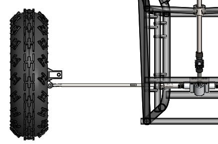
45 Upright Design Average Tire Turn Angle X = Mounting distance from axis of rotation = Rack Travel θ = 50.5 X = tan θ = tan 50.5 = 1.75 BAJA BENGALS 2015
46 Engineering Analysis and Material Selection Component Tensile Force Buckling Force Bending Moment Torsion Tie Rod N/A Lower Steering Shaft Upper Steering Shaft N/A N/A N/A N/A N/A N/A Tie Rod Material Modulus of Elasticity (ksi) Yield Strength (psi) Outside Diameter (in) Wall Thickness (in) Unit Weight (lb/ft) Price Per Foot ($/ft)* AISI 4130 Steel 29,700 70, AISI 2024 Aluminum 10,600 42, AISI 2024 Aluminum 10,600 42, * Price via McMaster-Carr.com
47 Steering Specifications Turning Diameter Rack Travel Steering Specifications 10 Feet 4.25 in lock-to-lock Steering Ratio 12:1 Number of Steering Wheel turns lock-to-lock 1.5 turns Average Tire Turning Angle 50.5 BAJA BENGALS 2015

48 BRAKES Functional Requirements Goals Constraints Concept Generation Engineering Analysis Final Design BAJA BENGALS 2015
49 Functional Requirements Cease Vehicle Motion Competition Requirements Effectively slow vehicle from speed Brake light Must lock all four wheels on pavement
50 Goals for Braking System Meet the requirements of competition Keep weight of overall system to a minimum Adjustable braking distribution Allow for easy driver exit
51 Engineering Constraints 2015 Baja SAE Rules and Regulations Hydraulic system At least two independent fluid circuits All brakes operated with a single foot pedal All brakes must illuminate brake light Rigid link between pedal and master cylinder(s) Braking on rear end must act through final drive
52 Engineering Constraints 10 wheel size for all four wheels Will need a brake for each front wheel Solid rear-end: - Only need one brake for rear wheels - 7 max disc diameter Open differential: - Will need a brake for all four wheels Limited space in foot box
53 Concept Generation and Selection Baja SAE Competition History Nearly all teams use hydraulic disc brakes Items to be addressed: Pedal type Master cylinder mounting and linkage Rear brake type


54 Concept Generation: Pedal Type Floor-mounted Pedal vs. Hanging Pedal Images from:


55 Concept Generation: Master Cylinder Location Forward vs. Rear-Facing Master Cylinder Images from

56 Concept Generation: Balance Bar and Bias Adjuster Linkage between pedal and master cylinders Adjustable braking distribution for each fluid circuit Images from


57 Concept Generation: Rear Brake Open Differential 2 discs & calipers cutting brakes Solid Rear-End Only one disc and caliper needed Central mounting location
58 Engineering Analysis Find braking force needed to decelerate the vehicle at 32.2 ft/s 2 Mass of car Inertial forces from rotating weight Find braking force needed to lock all four wheels on pavement
59 Analysis: Braking Force Static: F B * r disc = F F * r wheel F B = 2,450 lbs Dynamic: F B = ma(r wheel /r disc ) + (Iα/r disc ) BAJA BENGALS 2015 F B = 2,482 lbs
60 Analysis: Braking Force F B = (2 * F OUT ) * μ


61 Final Design BAJA BENGALS 2015 BAJA BENGALS 2015 BAJA BENGALS 2015 Total System Braking Force F B = 3,780 lbs


62 ELECTRONICS 1 Brake Light Switch 2 Circuit Components 3 Kill Switch Circuit 4 Component Details
63 Brake Light Switch BAJA BENGALS 2015
64 Circuit Components Brake Switches Activated by brake fluid pressure One switch for each fluid circuit Brake Light Must meet certain SAE standards 12 V, 200 ma
65 Circuit Components Battery 12 V, 2000 mah Brake light runtime: 10 hrs. Wire 22 AWG Voltage-drop: 3 mv/ft
66 Kill Switch Circuit BAJA BENGALS 2015
67 Component Details Kill Switches One switch in reach of driver One switch near firewall Pushing either switch interrupts ignition
68 Component Dimensions Battery Length in, Width in, Height 1.14 in Weight: 10 oz Brake Light Width in, Height in, Depth-.76 in

69 Safety
70 Safety in Car Design 2015 Baja SAE Rules and Regulations Frame: Protect the driver Mounting for safety harness & arm restraints Firewall, body panels, and belly pan Brakes: Two independent fluid circuits
71 Drivetrain Safety in Car Design Fuel splash guard Protective casing covering rotating components Two engine kill switches Other 5-point safety harness Fire extinguisher
72 Safety Moving Forward Driver Protection for Testing & Competition Motocross-style helmet Goggles with tear-offs or roll-offs Neck brace Gloves, pants, & a fire resistant long sleeve shirt
73 Testing Plans
74 Static Testing Technical Inspection 5 second driver exit test All drivers must fit in vehicle Brake Lights Kill Switches
75 Dynamic Testing Acceleration, Top Speed, & Dynamic Braking Hill Climb Suspension Steering & Maneuverability Endurance
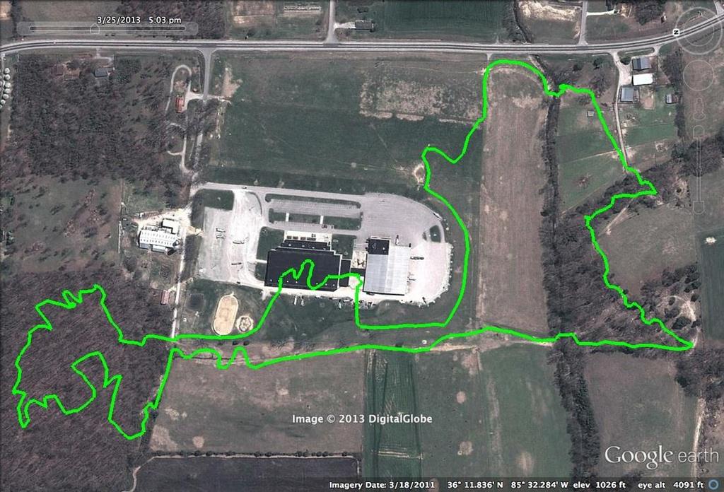
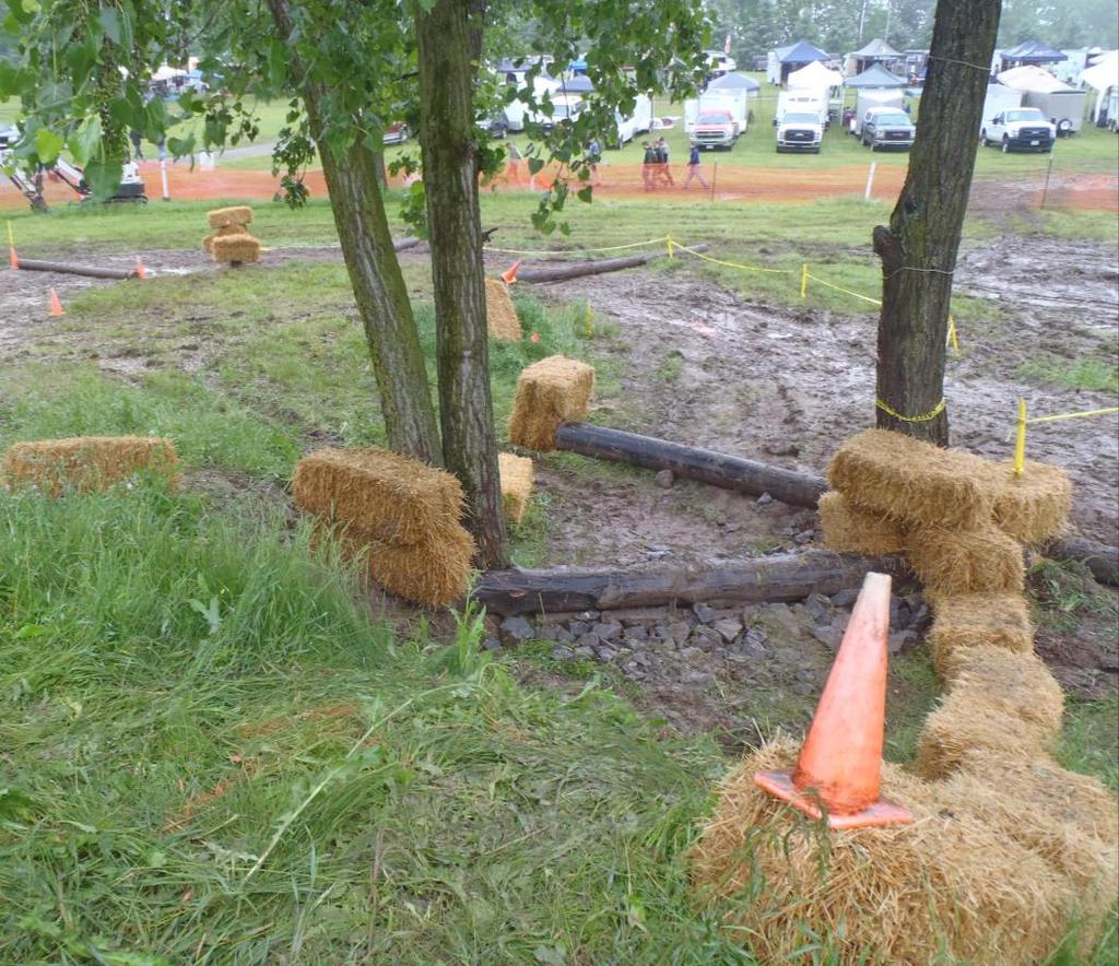
76 Testing Timeline & Locations Complete manufacturing one month before competition LSU permits for testing on campus Testing locations: Clint s camp, Spillway

77 Plans BAJA BENGALS 2015
78 Plans Frame Frame bends and profiling done by Cartesian Tube Profiling Tabs and brackets machined in house Drivetrain Gears and gear shafts to be outsourced Casing machined in house CVT and CV axles purchased from supplier Suspension A-Arms, Trailing arm, Sway bars, mounting brackets machined in house Spherical bearings, rod ends, ball joints, bushings, shock absorbers purchased BAJA BENGALS 2015

79 Plans Steering Rack and pinion purchased from supplier Tie rods, extensions, steering shaft, and all mounts and connections manufactured in house Braking All braking components to be purchased Mounting components to be manufactured in house Electrical Wire and soldering to be purchased BAJA BENGALS 2015

80 Final Design Estimated Weight= 375 lbs. Top Speed= 40 mph Max Incline= 35 degrees Turning Diameter= 10 feet Ground Clearance= 10 inches BAJA BENGALS 2015
81 Appendix
82 FRAME
83 FUNCTIONAL DECOMPOSITION: FRAME (DRIVER INTERFACE) Driver Interface Comfort Protection Components relative to driver Adequate space for driver Structural Support Around Driver Foot Pedals Foot Space Seatbelt Support Provided Steering Head Space Elbow Space Body Room
84 FUNCTIONAL DECOMPOSITION: FRAME (DRIVER INTERFACE) Component Interface Mounting Barrier between components & surroundings Suspension Support Drivetrain support Steering Support Brakes Pivot Points Rigid Support for Engine Allow Pivot for Steering Column Provide support for Brakes Shocks Gearbox Mounting Support Steering Mechanism
85 FRAME MATERIAL SELECTION MATERIAL AISI 1018 SAE 4130 (1) SAE 4130 (2) SAE 4130 (3) SAE 4130 (4) Modulus of Elasticity (kip) Yield Strength (kip) Outside Diameter (in) Wall Thickness (in) 29,732 29,732 29,732 29,732 29, Bending Strength (lb in) Bending Stiffness (lb in 2 ) 3,463 6,215 6,221 3,575 5, , ,581 1,217, , ,600 Unit Weight (lb/ft) Based on a density of.284 lb/in 3 (matweb.com). Equations Used: Bending Strength = S yi c Bending Stiffness = EI I = π 4 r o 4 r i 4
86 The purpose of this document is to aid in the design of the roll cage and serve as a checklist to pass technical inspection. Component List Primary RRH - Rear Roll Hoop RHO - Roll Hoop Overhead Members FBM - Front Bracing Members LC - Lateral Cross Member FLC - Front Lateral Cross Member Secondary LDB - Lateral Diagonal Bracing LFS - Lower Frame Side SIM - Side Impact Member FAB - Fore/Aft Bracing USM - Under Seat Member All Other Required Cross Members Any tube that is used to mount the safety belts
87 Material Requirements Primary Members: Circular steel tubing with an OD of 25mm (1.0in) and a wall thickness of 3mm (0.120in) and carbon content of at least 0.18%. Secondary Members: Circular steel tubing with a minimum OD of 25.4mm (1.0in) and having a minimum wall thickness of 0.89 mm (0.035in). Driver Spacing Head Minimum of 152mm (6in) of clearance from any space from the roll cage. Body Minimum of 76mm (3in) of clearance from any space from the roll cage. Note: Clearances are relative to any driver selected at technical inspection, seated in a normal driving position, and wearing all required equipment. No part of the driver s body may extend beyond the envelop of the roll cage. General Requirements Members which are not straight must not extend longer than 711mm (28in) between supports. Small bend radii (<152mm, 6in) at a supported end of a member are expected, and are not considered to make a member not straight The minor angle between the two ends of a not-straight tube must not exceed 30. No sharp edges. Notes Rules concerning the roll cage that are not necessary in the geometric design such as the welding process check, destructive testing samples, and roll cage specification sheet are not covered. Tube joints and bolted roll cages are not covered and are to be avoided in the geometric design of the roll cage. Rules in the regards to the constraints to the former statements should be referred to in the competition manual.
88 Lateral Cross Member (LC) Requirements - Primary Cannot be less than 203.5mm (8in) long. Cannot have a bend Can be a part of a larger bent tube system, between bends. Members that connect the left and right points of AF, SF, and C must be made of primary materials. Rear Roll Hoop (RRH) Requirements - Primary May be inclined by up to 20 from the vertical. Minimum width is 736mm (29in). Measured at a point 686mm (27in) above the inside seat bottom. Vertical members may be straight or bent. Defined at beginning and ending where they intersect the top and bottom horizontal planes. Points A r, A l, B r, B l in Figure 1. Vertical members must be continuous tubes. Vertical members must be joined by LC members at the top and bottom LC members must be continuous tubes. Must be diagonally braced. Must extend from one vertical member to the other Lateral Diagonal Bracing (LDB) Requirements - Secondary Top and bottom intersections between the diagonal bracing and rear roll hoop vertical members must be no more than 127mm (5in) from the top and bottom horizontal planes. The angle between the diagonal bracing and rear roll hoop vertical members must be greater than or equal to 20. Lateral bracing may consist of more than one member. Roll Hoop Overhead Member (RHO) Requirements - Primary Point C in Figure 3 must be at least 305mm (12in) forward from a point in the vehicle s elevation view. Point C is defined as the forward end of the roll hoop overhead member. Defined by the intersection of the roll hoop overhead members and a vertical line rising from the after end of the seat bottom. The point on the seat is defined by the seat bottom intersection with a 101mm (4in) radius circle which touches the seat bottom and the seat back. The top edge of the template is exactly horizontal with respect to gravity. Point C in Figure 3 must not be lower than the top edge of the top edge of the template mm (41in) above the seat.
89 Lower Frame Side Member (LFS) Requirements - Secondary Define the lower right and left edges of the roll cage. Joined to the bottom of the rear roll hoop and extend forward to at least as far as the driver s heels when seated in a normal driving position. Forward ends are joined by the front lateral cross member. Point AF. Side Impact Member (SIM) Requirements - Secondary Define a horizontal mid-plane within the roll cage Joined to the rear roll hoop and extend forward to at least as far as a point forward of the driver s toes, when seated in a normal driving position. Forward ends are joined by a lateral cross. Define the point SF. Must be between 203mm (8in) and 356mm (14in) above the inside seat bottom. Figure 3. Under Seat Member (USM) Requirements - Secondary Must join the lower frame side members. Must pass directly below the driver. Where the template in Figure 3 intersects the seat bottom. Must be positioned in such a way to prevent the driver from passing through the plane of the lower frame side members in the event of seat failure. Front Bracing Member (FBM) Requirements - Primary Must join the roll hoop overhead, side impact, and lower frame side members. Figure 5. Upper front bracing member must join point C on the roll hoop overhead to the side impact member at or behind point SF. Lower front bracing member must join point AF to SF. Must be continuous tube. Angle between the upper front bracing member and the vertical must be less than or equal to 45. If the roll hoop overhead and front bracing member on at least one side of the vehicle are no comprised jointly of one tube, bent near point C, then a gusset is required at point C. To support the joint between the roll hoop overhead and front bracing members. The total weld length of the gusset must be 2 times the tubing circumference (of the primary material). If a tube is used to brace the front bracing and roll hoop overhead members, it must be a primary tube.
90 Fore/Aft Bracing (FAB) Requirements - Secondary Note: Better design will result if both front and rear are incorporated. Rear Bracing Directly restrain point B from longitudinal displacement in the event of failure of the joints at point C. Must create a structural triangle. Must be same on both sides. Each triangle must be aft of the rear roll hoop. Must include the rear roll hoop vertical as a member. Must have one vertex near point B and one vertex near either point S or point A. The third vertex of each rear bracing triangle must additionally be structurally connected to whichever point, S or A, is not part of the structural triangle. This additional connection is considered part of the fore/aft bracing system. Subject to B May be formed using multiple joined members. Assembly of tubes, from endpoint to endpoint, may encompass a bend of greater than 30 degrees. Attachment of the rear fore/aft bracing system must be within 127mm (5in) of point B. Must be within 51mm (2in) of point S and A. The rear bracing structural triangles must not be angled more than 20 degrees from the vehicle centerline. The after vertices of the fore/aft bracing structural triangles must be joined by a lateral cross. Or Front Bracing Restrain point C from longitudinal and vertical displacement. Supporting point B through the roll hoop overhead member. Must connect the upper front bracing member to the side impact member. Must be same on both sides. The intersection with the upper front bracing member must be within 127mm (5in) of point C. The intersection with the side impact member must be vertically supported by further members connecting the side impact member to the lower frame side member.
91 PRIMARY SECONDARY 1. Rear Roll Hoop 1. Lateral Diagonal Bracing 2. Roll Hoop Overhead Members 2. Side Impact Member 3. Front Bracing Members 3. Fore Bracing 4. Lateral Cross Members 4. Under Seat Members 5. Front Lateral Cross Member 6. Lower Frame Side Member
92 Drivetrain
93

94
95
96 Analysis: Gearbox Minimum Gear Ratio to Climb Incline: GRAVITY G1 G2 GRAVITY 35 Top Speed with Minimum Gear Ratio: 3800 RPM MAX ENGINE SPEED 228,000 ROT/HOUR 0.9:1 FINAL CVT RATIO TIRE RADIUS = 0.9 FT TIRE ROLLOUT: (2π)*(0.9 FT) = FT DISTANCE PER ROT ENG = ( FT) / (0.9*6.76) = FT/ROT ENG (228,000 ROT/HR)*( FT/ROT) = 211, FT/HR (211, FT/HR)*[(1 MILE) / (5280 FT)] = MPH TOP 3800 RPM = 40 MPH TIRE RADIUS: 0.9 FT CVT LOW RATIO: 3.9:1 VEHICLE WEIGHT W/DRIVER: 600 LBS MAX INCLINE ANGLE: 35 DEGRESS (VEHICLE WEIGHT)*(sin (INCLINE ANGLE))= REPELLING WEIGHT (600lbs) * (sin(35))= lbs REPELLING WEIGHT =(TIRE RADIUS)*(CVT RATIO)*(ENGINE TQ)*(X MIN) LBS= (0.9 FT) x (3.9) x (14.5 ft-lbs) x (X MIN) X MIN= 6.76


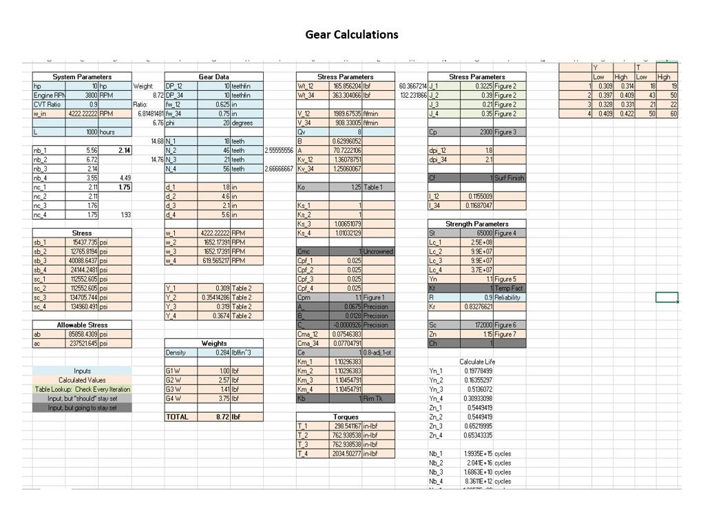
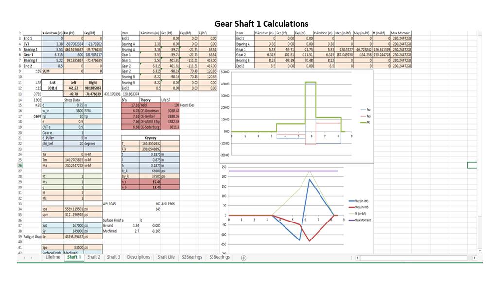
97 Analysis: Gears BAJA BENGALS 2015 BAJA BENGALS 2015 Displacement of gear tooth with 385 ft-lb force Stress on gear tooth using 4340 Steel Bending and Contact stresses calculated with AGMA equations Factor of safety was also calculated from these equations SafetyTesting
98 Suspension


99 Fox Float 3 EVOL R Source: Joey Avilla (Fox Racing)
100 Force (lb) Approximated Spring Coefficient 1600 Spring Coefficient of Fox Float 3 EVOL R y = e x R² = Shock Stroke (in)

101 Fox Float 3 EVOL R Source: Joey Avilla (Fox Racing)

102 Fox Float 3 EVOL R Source: Joey Avilla (Fox Racing)

103 Fox Float 3 EVOL R
104 Motion Ratio Desired Wheel Travel Shock Stroke = Radial Wheel Distance Shock Placement Front: Shock Placement = 18" ( 5.3" 12" ) = 7.95 Rear: Shock Placement = 26" ( 5.3" 12" ) = 11.5
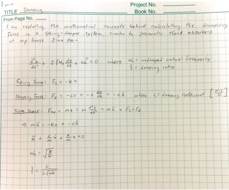
105 Damping
106 Impact Force
107 Impact Force cont.


108 Lower A-Arm

109 Lower A-Arm

110 Trailing Arm F=1500 lbf

111 Pin Shear
112 Bump Steer
113 Steering

114 Functional Decomposition Steering System Control Vehicle Direction System Integration Safety Rotate Wheels Compatible With Suspension Removable Steering Wheel User Input Lightweight Unobstructed Egress Tight Turn Radius Durable Enclosed Mechanisms Maintain Direction Driver Comfort Safety/Testing
115 Brakes
116 Braking Force Calculations r wheel = 10.5 inches = ft r disc = 3 inches = 0.25 ft (effective braking radius) I = slug*ft 2 (For all 4 wheels) a = 32.2 ft/s 2 (linear deceleration) α = 36.8 rad/s 2 (angular deceleration) m = slugs (vehicle plus driver and fluids)
117 Braking Force Calculations F B *r disc = I*α Eq. 1 Slowing rotating mass F B *r disc = m*a*r wheel Eq. 2 Slowing moving mass Combining Eq. 1 and Eq.2 for total braking force F B = ma(r wheel /r disc ) + Iα/r disc
118 Electronics

119 Battery charger circuit

120 Battery charger simulation
121 Organization
122 Timeline Order Frame 12/8/14 Begin and Assemble Frame 12/19 Drivetrain Assembled 1/25/14 Suspension Assembled 1/25/14 Steering Assembled 2/3/14 Brakes Assembled 2/18/14 Begin Testing 3/1/15 5 Weeks Prior to Competition

123 Key Takeaways Complete SolidWorks Assembly Discovered Importance of Engineering Design Process & Documentation Jump started Baja as a Student Organization Understanding of how to apply theory learned in classes to a practical application LSU Baja Bengals Team: Developed Team Chemistry in Order to have a Successful Spring Semester
Supports for the exhaust pipe and muffler are required. Supports must be attached exclusively to the engine.
 Exhaust System Muffler Relocation If the vehicle design requires an exhaust system reconfiguration to keep it from impinging on part of the vehicle, the re-routing must be done using tubing having an ID
Abstract. Figure 1: Rendered Prototype Model Created By 2015 Baja Bengals
 Final Report Team 40: Mini-Baja Project LSU Capstone Mechanical Engineering Written by: Lance Angelle, Clinton Bourgeois, James Burgard, Colby Cheneval, Kevin Hall, Hannah Neitzke, Kevin Sextro, Carey
SAE Mini Baja. Frame Team. Ahmed Alnattar, Neil Gehr, Matthew Legg. Project Proposal
 SAE Mini Baja Frame Team Project Proposal Ahmed Alnattar, Neil Gehr, Matthew Legg 12-3-14 1 Overview Introduction Customer s Needs and Project Goals Constraints, Objectives, QFD, and Timeline Concept Generation
SAE Mini Baja. Final Presentation. Benjamin Bastidos, Jeramie Goodwin, Eric Lockwood Anthony McClinton, Caizhi Ming, Ruoheng Pan May 2, 2014
 SAE Mini Baja Final Presentation Benjamin Bastidos, Jeramie Goodwin, Eric Lockwood Anthony McClinton, Caizhi Ming, Ruoheng Pan May 2, 2014 Overview Project Introduction Need Statement Frame Design and
2018 BAJA SAE Technical Inspection Sheet
 08 BAJA SAE Technical Inspection Sheet School: DRIVER 5 DRIVER 9 DRIVER DRIVER 6 DRIVER 0 DRIVER 3 DRIVER 7 DRIVER DRIVER 4 DRIVER 8 DRIVER DRIVER Competition: Vehicle # Transponder Transponder Front Tires
2017 Baja SAE Competition
 2017 Baja SAE Competition Meet the Team Enrique DeLeon Manjula Hodekar Keith Hernandez Mechanical Lead Public Relations Design Lead Logistics Team Lead Project Management Instructor: Dr. Raresh Pascali
SAE Baja Design/Manufacturing Project. (MECET, Design Emphasis)
") 2016-2017 SAE Baja Design/Manufacturing Project Hani Alnakhly Mohnannad Gazzaz Azmi Awari Turki Al-Rashid Sultan Alshammari Abraham Ittycheri (MECET, Design Emphasis) (MECET, Design Emphasis) (MECET, Design
2016-2017 SAE Baja Design/Manufacturing Project Hani Alnakhly Mohnannad Gazzaz Azmi Awari Turki Al-Rashid Sultan Alshammari Abraham Ittycheri (MECET, Design Emphasis) (MECET, Design Emphasis) (MECET, Design
2014 BAJA SAE Technical Inspection Sheet School Name Vehicle #
 Instructions: 2014 BAJA SAE Technical Inspection Sheet School Name Vehicle # Drivers for this Car ONLY! 1 2 3 4 5 6 7 8 9 10 11 12 13 14 Transponder #'s 15 Drivetrain Certification Form Rim Size: Rim Size:
SAE Mini BAJA: Suspension and Steering
 SAE Mini BAJA: Suspension and Steering By Zane Cross, Kyle Egan, Nick Garry, Trevor Hochhaus Team 11 Progress Report Submitted towards partial fulfillment of the requirements for Mechanical Engineering
SAE Mini Baja: Suspension and Steering
 SAE Mini Baja: Suspension and Steering Project Proposal Zane Cross, Kyle Egan, Nick Garry, Trevor Hochhaus NAU December 3, 2014 Overview 2 Problem Definition and Project Plan Concept Generation Design
COWBOY MOTORSPORTS SENIOR DESIGN Scott Dick Garrett Dollins Logan Gary
 COWBOY MOTORSPORTS SENIOR DESIGN 2016-2017 Scott Dick Garrett Dollins Logan Gary 2016-2017 ASABE INTERNATIONAL QUARTER SCALE TRACTOR STUDENT DESIGN COMPETITION COMPETITION OVERVIEW Design report 500 pts
SAE Baja: Project Proposal Suspension and Steering
 SAE Baja: Project Proposal Suspension and Steering Benjamin Bastidos, Victor Cabilan, Jeramie Goodwin, William Mitchell, Eli Wexler Wednesday, November 20, 2013 Overview Introduction Concept Generation
Design And Development Of Roll Cage For An All-Terrain Vehicle
 Design And Development Of Roll Cage For An All-Terrain Vehicle Khelan Chaudhari, Amogh Joshi, Ranjit Kunte, Kushal Nair E-mail : khelanchoudhary@gmail.com, amogh_4291@yahoo.co.in,ranjitkunte@gmail.com,krockon007@gmail.com
University of San Diego 2017 SAE Baja
 University of San Diego 2017 SAE Baja Society of Automotive Engineers University of San Diego Student Chapter University of San Diego SAE Shiley Marcos School of Engineering 5998 Alcala Park San Diego,
Chassis. Introduction. Design Objectives
 Chassis Introduction Purpose and Goals The chassis is the backbone of the Mini-Baja; it must support all the car s subassemblies as well as protect the driver. The chassis design is crucial to the success
Fundamentals of Steering Systems ME5670
 Fundamentals of Steering Systems ME5670 Class timing Monday: 14:30 Hrs 16:00 Hrs Thursday: 16:30 Hrs 17:30 Hrs Lecture 3 Thomas Gillespie, Fundamentals of Vehicle Dynamics, SAE, 1992. http://www.me.utexas.edu/~longoria/vsdc/clog.html
CETYS Universidad Baja SAE Design Report
 Copyright 2007 SAE International Vehicle #28 CETYS Universidad Baja SAE Design Report Gustavo Ovies, Andres Magaña, Alejandro Burgas Iván Pulido, Iván Williams, Bernardo Valadez Mechanical engineering
DESIGN AND ANALYSIS OF PUSH ROD ROCKER ARM SUSPENSION USING MONO SPRING
 Volume 114 No. 9 2017, 465-475 ISSN: 1311-8080 (printed version); ISSN: 1314-3395 (on-line version) url: http://www.ijpam.eu ijpam.eu DESIGN AND ANALYSIS OF PUSH ROD ROCKER ARM SUSPENSION USING MONO SPRING
Design and Integration of Suspension, Brake and Steering Systems for a Formula SAE Race Car
 Design and Integration of Suspension, Brake and Steering Systems for a Formula SAE Race Car Mark Holveck 01, Rodolphe Poussot 00, Harris Yong 00 Final Report May 5, 2000 MAE 340/440 Advisor: Prof. S. Bogdonoff
General Vehicle Information
 Vehicle #3921 Chevrolet Equinox (2CNALBEW8A6XXXXXX) Inspection Date: 1-Feb-211 Year 21 Make Model Body Style HVE Display Name: Year Range: Sisters and Clones: Vehicle Category: Vehicle Class: VIN: Date
ME 455 Lecture Ideas, Fall 2010
 ME 455 Lecture Ideas, Fall 2010 COURSE INTRODUCTION Course goal, design a vehicle (SAE Baja and Formula) Half lecture half project work Group and individual work, integrated Design - optimal solution subject
Mini Baja Vehicle Design Optimization
 Mini Baja Vehicle Design Optimization MIE U970-U971 Technical Design Report Mini Baja Vehicle Design Optimization Honors Thesis: Final Report Student: Jonathan Hastie Design Advisor: Prof. Hashemi Fall
Design Presentation ROADIES. Regd. ID : National Institute of Foundry & Forge Technology, Ranchi L/O/G/O.
 Design Presentation ROADIES Regd. ID : 81341 National Institute of Foundry & Forge Technology, Ranchi L/O/G/O www.themegallery.com TEAM ORGANIZATION TEAM CAPTAIN TEAM VICE-CAPTAIN RICHARD DOLEY AKSHAY
OLD DOMINION UNIVERSITY. SAE Baja. Final Report. Frame Suspension Drivetrain. Dan D Amico Peter Morabito Kenneth Elliot
 OLD DOMINION UNIVERSITY SAE Baja Final Report Frame Suspension Drivetrain Dan D Amico Peter Morabito Kenneth Elliot Curtis May Michael Paliga Patrick Mooney Greg Schaffran Brian Ross Dylan Quinn Faculty
SAE NAU Mini Baja. Background Report
 SAE NAU Mini Baja Background Report Quinton Astgen Thomas Baker Brody Beebe Jon Bloot Jake Hinkle Dustin Odorcic 2016-17 Project Sponsor: Society of Automotive Engineers (SAE) Faculty Advisor: John T.
2013 Baja SAE Drivetrain
 2013 Baja SAE Drivetrain A Baccalaureate thesis submitted to the School of Dynamic Systems College of Engineering and Applied Science University of Cincinnati in partial fulfillment of the requirements
Design and Front Impact Analysis of Rollcage
 International Conference on Challenges and Opportunities in Mechanical Engineering, Industrial Engineering and Management Studies 7 Design and Front Impact Analysis of Rollcage Gautam Yadav and Ankit Jain
University of Wisconsin-Platteville Formula SAE Design Report
 2012-2013 University of Wisconsin-Platteville Formula SAE Design Report Introduction The 2012-2013 University of Wisconsin-Platteville Formula SAE Team is competing in Formula SAE, Nebraska, for the second
R10 Set No: 1 ''' ' '' '' '' Code No: R31033
 R10 Set No: 1 III B.Tech. I Semester Regular and Supplementary Examinations, December - 2013 DYNAMICS OF MACHINERY (Common to Mechanical Engineering and Automobile Engineering) Time: 3 Hours Max Marks:
ISSN: [Patil et al., 5(10): October, 2016] Impact Factor: 4.116
![ISSN: [Patil et al., 5(10): October, 2016] Impact Factor: 4.116](/thumbs/83/88212336.jpg "ISSN: [Patil et al., 5(10): October, 2016] Impact Factor: 4.116") IJESRT INTERNATIONAL JOURNAL OF ENGINEERING SCIENCES & RESEARCH TECHNOLOGY DESIGN AND ANALYSIS OF TELESCOPIC HALFSHAFT FOR AN ALL-TERRAIN VEHICLE (ATV) Chirag Patil *, Sandeep Imale, Kiran Hiware, Sumeet
IJESRT INTERNATIONAL JOURNAL OF ENGINEERING SCIENCES & RESEARCH TECHNOLOGY DESIGN AND ANALYSIS OF TELESCOPIC HALFSHAFT FOR AN ALL-TERRAIN VEHICLE (ATV) Chirag Patil *, Sandeep Imale, Kiran Hiware, Sumeet
WPI SAE Baja Vehicle
 2013-2014 WPI SAE Baja Vehicle A Major Qualifying Project Submitted to the faculty of Worcester Polytechnic Institute in partial fulfillment of the requirements for the Degree of Bachelor of Science Submitted
SAE Mini BAJA: Suspension and Steering
 SAE Mini BAJA: Suspension and Steering By Zane Cross, Kyle Egan, Nick Garry, Trevor Hochhaus Team 11 Project Progress Submitted towards partial fulfillment of the requirements for Mechanical Engineering
SAE Baja - Drivetrain
 SAE Baja - Drivetrain Project Proposal Ricardo Inzunza, Brandon Janca, Ryan Worden December 3, 2014 Overview Introduction Needs and Constraints QFD/HOQ Problem Definition and Project Goal Transmission
Design, Static and Dynamic analysis of an All- Terrain Vehicle Chassis and Suspension System
 Design, Static and Dynamic analysis of an All- Terrain Vehicle Chassis and Suspension System 1 Mr. Dibya Narayan Behera, 2 Rajesh Kumar, 3 Kunal Abhishek, 4 Sunil Kumar Panda 1 Asst. Professor, 2 Under
Design and Analysis of suspension system components
 Design and Analysis of suspension system components Manohar Gade 1, Rayees Shaikh 2, Deepak Bijamwar 3, Shubham Jambale 4, Vikram Kulkarni 5 1 Student, Department of Mechanical Engineering, D Y Patil college
2012 Dalhousie University Formula SAE Design Report
 Dalhousie University Car #47 - Formula SAE Michigan fsae@dal.ca Introduction 2012 Dalhousie University Formula SAE Design Report The 2012 Dalhousie University Formula SAE Team is competing in Formula SAE,
2014 University of Cincinnati Baja SAE Braking System
 2014 University of Cincinnati Baja SAE Braking System A Baccalaureate thesis submitted to the School of Dynamic Systems College of Engineering and Applied Science University of Cincinnati In partial fulfillment
Design of Suspension and Steering system for an All-Terrain Vehicle and their Interdependence
 Design of Suspension and Steering system for an All-Terrain Vehicle and their Interdependence Saurabh Wanganekar 1, Chinmay Sapkale 2, Priyanka Chothe 3, Reshma Rohakale 4,Samadhan Bhosale 5 1 Student,Department
Northern Arizona University Baja SAE Owner s Manual
 Northern Arizona University Baja SAE 2016 Owner s Manual Contents Vehicle Overview... 2 Safety Equipment... 3 Seat... 3 Safety Harness... 3 Emergency Stop... 3 Fire Extinguisher... 3 Vehicle Operation...
ASME Human Powered Vehicle
 ASME Human Powered Vehicle By Yousef Alanzi, Evan Bunce, Cody Chenoweth, Haley Flenner, Brent Ives, and Connor Newcomer Team 14 Mid-Point Review Document Submitted towards partial fulfillment of the requirements
Torque steer effects resulting from tyre aligning torque Effect of kinematics and elastokinematics
 P refa c e Tyres of suspension and drive 1.1 General characteristics of wheel suspensions 1.2 Independent wheel suspensions- general 1.2.1 Requirements 1.2.2 Double wishbone suspensions 1.2.3 McPherson
Mini Baja Advisory Presentation May 2, 2008
 Mini Baja Advisory Presentation May 2, 2008 Presenter: Mark Bell Accompanied by Baja Team 83 Member Jerrod Bohannon Table of Contents Overview of Competition Design Conditions Grading Criteria Design Concepts
DESIGN AND ANALYSIS OF AN OFF ROAD VEHICLE (ALL TERRAIN VEHICLE)
") DESIGN AND ANALYSIS OF AN OFF ROAD VEHICLE (ALL TERRAIN VEHICLE) 1 Bibek Kumar Giri, 2 Shakti Prasanna Khadanga, 3 Abhijeet Nanda, 4 Guru Prasad Behera, 5 Amit Kumar Munda, 6 Nandan Meher. 1,3,4,5,6 Students,
DESIGN AND ANALYSIS OF AN OFF ROAD VEHICLE (ALL TERRAIN VEHICLE) 1 Bibek Kumar Giri, 2 Shakti Prasanna Khadanga, 3 Abhijeet Nanda, 4 Guru Prasad Behera, 5 Amit Kumar Munda, 6 Nandan Meher. 1,3,4,5,6 Students,
F.I.R.S.T. Robotic Drive Base
 F.I.R.S.T. Robotic Drive Base Design Team Shane Lentini, Jose Orozco, Henry Sick, Rich Phelan Design Advisor Prof. Sinan Muftu Abstract F.I.R.S.T. is an organization dedicated to inspiring and teaching
SAE Mini Baja By Ahmed Alnattar, Neil Gehr, and Matthew Legg Team 11
 SAE Mini Baja 2014-2015 By Ahmed Alnattar, Neil Gehr, and Matthew Legg Team 11 Final Report Document April 22, 2015 Submitted towards partial fulfillment of the requirements for Mechanical Engineering
A Guide to Successful Baja SAE Technical Inspection. June 2017
 A Guide to Successful Baja SAE Technical Inspection June 2017 Outline Introduction Paperwork Frame Driver Safety Braking Guards Body and Cockpit Fuel Electrical Fasteners What slows down technical inspection
A double-wishbone type suspension is used in the front. A multi-link type suspension is used in the rear. Tread* mm (in.) 1560 (61.
 1560 (61.") CHASSIS SUSPENSION AND AXLE CH-69 SUSPENSION AND AXLE SUSPENSION 1. General A double-wishbone type suspension is used in the front. A multi-link type suspension is used in the rear. 08D0CH111Z Specifications
CHASSIS SUSPENSION AND AXLE CH-69 SUSPENSION AND AXLE SUSPENSION 1. General A double-wishbone type suspension is used in the front. A multi-link type suspension is used in the rear. 08D0CH111Z Specifications
Society of Automotive Engineers Baja Vehicle Design and Fabrication
 2017-2018 Society of Automotive Engineers Baja Vehicle Design and Fabrication A Major Qualifying Project Submitted to the faculty of Worcester Polytechnic Institute In partial fulfillment of the requirements
SAE Baja: Suspension & Steering Benjamin Bastidos, Victor Cabilan, Jeramie Goodwin, William Mitchell, Eli Wexler
 SAE Baja: Suspension & Steering Benjamin Bastidos, Victor Cabilan, Jeramie Goodwin, William Mitchell, Eli Wexler Wednesday, October 9, 2013 Overview Introduction Operating Environment Recognizing the Need
DESIGN OF CHASSIS OF STUDENT FORMULA RACE CAR
 DESIGN OF CHASSIS OF STUDENT FORMULA RACE CAR Shubhanandan Dubey 1, Rahul Jaiswal 2, Raunak Mishra 3 1, 2, 3 Department of Automobile, Theem College of Engineering, University of Mumbai, Maharashtra, India
EXAMPLES INTRODUCTION
 AMEM 316 (AUTO308): Machine Elements I EXAMPLES INTRODUCTION EXAMPLES INTRODUCTION Example 1 (Hamrock p.53) As shown in figure 2.12(a), a 3m long bar is supported at the left end (B) by a 6 ram diameter
III B.Tech I Semester Supplementary Examinations, May/June
 Set No. 1 III B.Tech I Semester Supplementary Examinations, May/June - 2015 1 a) Derive the expression for Gyroscopic Couple? b) A disc with radius of gyration of 60mm and a mass of 4kg is mounted centrally
Off Road Innovations. Design of an Off-Road Suspension and Steering System. EN Mechanical Design Project II - Progress Report 1
 Off Road Innovations Design of an Off-Road Suspension and Steering System EN 8926 - Mechanical Design Project II - Progress Report 1 Andrew Snelgrove 200832467 Calvin Holloway 200814416 Jeremy Sheppard
Design and Optimisation of Roll Cage of a Single Seated ATV
 IOSR Journal of Mechanical and Civil Engineering (IOSR-JMCE) e-issn: 2278-1684,p-ISSN: 2320-334X, Volume 12, Issue 2 Ver. III (Mar - Apr. 2015), PP 56-61 www.iosrjournals.org Design and Optimisation of
Northern Arizona University Baja SAE Owner s Manual
 Northern Arizona University Baja SAE 2015 Owner s Manual Contents Vehicle Overview... 2 Safety Equipment... 3 Seat... 3 Safety Harness... 3 Emergency Stop... 3 Fire Extinguisher... 3 Vehicle Operation...
Northern Arizona University Baja SAE Owner s Manual
 Northern Arizona University Baja SAE 2014 Owner s Manual Contents Vehicle Overview... 2 Safety Equipment... 3 Seat... 3 Safety Harness... 3 Emergency Stop... 3 Fire Extinguisher... 3 Vehicle Operation...
Design & Manufacturing of an Effective Steering System for a Formula Student Car
 Design & Manufacturing of an Effective Steering System for a Formula Student Car Nikhil N. Gitay 1, Siddharth A. Joshi 2, Ajit A. Dumbre 3, Devesh C. Juvekar 4 1,2,3,4 Student, Department of Mechanical
Design and Optimisation of Sae Mini Baja Chassis
 RESEARCH ARTICLE OPEN ACCESS Design and Optimisation of Sae Mini Baja Chassis P. Anjani Devi*, A. Dilip** *(Department of Mechanical Engineering, Chaitanya Bharati Institute of technology, Hyderabad-75)
Formula SAE Workshop October 25 th MAJOR RULES CHANGES for 2009
 Formula SAE Workshop October 25 th 2008 MAJOR RULES CHANGES for 2009 Michael Royce FSAE Workshop 10.25.2008 1 2009 FSAE Rules - Changes Format Index Introduction Part A - Administrative Regulations Part
SAE Baja - Drivetrain
 SAE Baja - Drivetrain By Ricardo Inzunza, Brandon Janca, Ryan Worden Team 11 Engineering Analysis Document Submitted towards partial fulfillment of the requirements for Mechanical Engineering Design I
Designing and Hard Point Optimization of Suspension System of a Three-Wheel Hybrid Vehicle
 ISSN (O): 2393-8609 International Journal of Aerospace and Mechanical Engineering Designing and Hard Point Optimization of Suspension System of a Three-Wheel Hybrid Vehicle Gomish Chawla B.Tech Automotive
2012 Baja SAE Drivetrain
 2012 Baja SAE Drivetrain A thesis submitted to the Faculty of the Mechanical Engineering Technology Program of the University of Cincinnati in partial fulfillment of the requirements for the degree of
Finite Element Modeling and Analysis of Vehicle Space Frame with Experimental Validation
 Finite Element Modeling and Analysis of Vehicle Space Frame with Experimental Validation Assoc. Prof Dr. Mohammed A.Elhaddad Mechanical Engineering Department Higher Technological Institute, Town of 6
New Frontier in Energy, Engineering, Environment & Science (NFEEES-2018 ) Feb
 Feb") RESEARCH ARTICLE OPEN ACCESS DESIGN AND IMPACT ANALYSIS OF A ROLLCAGE FOR FORMULA HYBRID VEHICLE Aayush Bohra 1, Ajay Sharma 2 1(Mechanical department, Arya College of Engineering & I.T.,kukas, Jaipur)
RESEARCH ARTICLE OPEN ACCESS DESIGN AND IMPACT ANALYSIS OF A ROLLCAGE FOR FORMULA HYBRID VEHICLE Aayush Bohra 1, Ajay Sharma 2 1(Mechanical department, Arya College of Engineering & I.T.,kukas, Jaipur)
DESIGN AND DEVELOPMENT OF IC ENGINE GO-KART
 DESIGN AND DEVELOPMENT OF IC ENGINE GO-KART AkshayB. Khot 1, KunalJ. Mahekar 2, VaibhavJ. Mahekar 3, GurunathS. Patil 4, MohanishM. Patil 5, Prof. S. P. Jarag 6 BE Student, Department of Mechanical Engineering,
2010 Sponsorship Information Package
 2010 Sponsorship Information Package 1 Contents Introduction 3 What is Formula SAE 4 Formula SAE Concept 5 Competition Regulations 6 University of Kentucky in FSAE 7 Sponsorship Benefits 8 Sponsorship
University of Alberta Design Report
 University of Alberta Design Report INTRODUCTION The University of Alberta has been a competitor in the Formula SAE competition since 1999. Those years of experience have provided the team with many lessons
Introduction. Kinematics and Dynamics of Machines. Involute profile. 7. Gears
 Introduction The kinematic function of gears is to transfer rotational motion from one shaft to another Kinematics and Dynamics of Machines 7. Gears Since these shafts may be parallel, perpendicular, or
Structural Analysis of Student Formula Race Car Chassis
 Structural Analysis of Student Formula Race Car Chassis Arindam Ghosh 1, Rishika Saha 2, Sourav Dhali 3, Adrija Das 4, Prasid Biswas 5, Alok Kumar Dubey 6 1Assistant Professor, Dept. of Mechanical Engineering,
2016 Baja SAE Series Frame Design
 2016 Baja SAE Series Frame Design A Baccalaureate thesis submitted to the Department of Mechanical and Materials Engineering College of Engineering and Applied Science University of Cincinnati in partial
SAE Baja Design Final Design Presentation Team Drivetrain. By Abdulrahman Almuflih, Andrew Perryman, Caizhi Ming, Zan Zhu, Ruoheng Pan
 SAE Baja Design Final Design Presentation Team Drivetrain By Abdulrahman Almuflih, Andrew Perryman, Caizhi Ming, Zan Zhu, Ruoheng Pan Overview Introduction Concept Generation and Selection Engineering
TECHNICAL NOTE. NADS Vehicle Dynamics Typical Modeling Data. Document ID: N Author(s): Chris Schwarz Date: August 2006
: Chris Schwarz Date: August 2006") TECHNICAL NOTE NADS Vehicle Dynamics Typical Modeling Data Document ID: N06-017 Author(s): Chris Schwarz Date: August 2006 National Advanced Driving Simulator 2401 Oakdale Blvd. Iowa City, IA 52242-5003
TECHNICAL NOTE NADS Vehicle Dynamics Typical Modeling Data Document ID: N06-017 Author(s): Chris Schwarz Date: August 2006 National Advanced Driving Simulator 2401 Oakdale Blvd. Iowa City, IA 52242-5003
A TECHNICAL INSPECTOR S GUIDE TO THE 2012 FSAE RULES PART 2 DRIVER S EQUIPMENT & EXTERIOR GENERAL
 A TECHNICAL INSPECTOR S GUIDE TO THE 2012 FSAE RULES PART 2 DRIVER S EQUIPMENT & EXTERIOR GENERAL B.17. Driver s Equipment B.17.1 Driver s Equipment The following equipment must be worn by the driver anytime
B.TECH III Year I Semester (R09) Regular & Supplementary Examinations November 2012 DYNAMICS OF MACHINERY
 Regular & Supplementary Examinations November 2012 DYNAMICS OF MACHINERY") 1 B.TECH III Year I Semester (R09) Regular & Supplementary Examinations November 2012 DYNAMICS OF MACHINERY (Mechanical Engineering) Time: 3 hours Max. Marks: 70 Answer any FIVE questions All questions
1 B.TECH III Year I Semester (R09) Regular & Supplementary Examinations November 2012 DYNAMICS OF MACHINERY (Mechanical Engineering) Time: 3 hours Max. Marks: 70 Answer any FIVE questions All questions
University of Wisconsin-Platteville Society of Automotive Engineers Mini Baja Team
 University of Wisconsin-Platteville Society of Automotive Engineers Mini Baja Team 2009 Design Report SAE Mini Baja Wisconsin Competition, June 11-14, 2009 Copyright 2007 SAE International Vehicle Number
Design of Formula SAE Suspension
 SAE TECHNICAL PAPER SERIES 2002-01-3310 Design of Formula SAE Suspension Badih A. Jawad and Jason Baumann Lawrence Technological University Reprinted From: Proceedings of the 2002 SAE Motorsports Engineering
Maverick Engineering Personal Transportation Vehicle. Brian Wolfe Joe Bilinski Tim Ferlin Mike Schiavone
 Maverick Engineering Personal Transportation Vehicle Brian Wolfe Joe Bilinski Tim Ferlin Mike Schiavone Overview Design Goals Design Discussion Performance Testing and Competition Areas for Improvement
SAE Mini Baja: Suspension and Steering. Project Proposal
 SAE Mini Baja: Suspension and Steering By Benjamin Bastidos, Victor Cabilan, Jeramie Goodwin, William Mitchell, Eli Wexler Team 19 Project Proposal Document Submitted towards partial fulfillment of the
DRIVE-CONTROL COMPONENTS
 3-1 DRIVE-CONTROL COMPONENTS CONTENTS FRONT SUSPENSION................... 2 Lower Arms............................... 5 Strut Assemblies........................... 6 REAR SUSPENSION.....................
DESIGNING OF THE RACK AND PINION GEARBOX FOR ALL TERRAIN VEHICLE FOR THE COMPETITION BAJA SAE INDIA AND ENDURO STUDENT INDIA
 DESIGNING OF THE RACK AND PINION GEARBOX FOR ALL TERRAIN VEHICLE FOR THE COMPETITION BAJA SAE INDIA AND ENDURO STUDENT INDIA Omkar Diliprao Suryavanshi 1, Prathmesh Prasad Sathe 2, Mahesh Ashokrao Takey
Design, analysis and mounting implementation of lateral leaf spring in double wishbone suspension system
 Design, analysis and mounting implementation of lateral leaf spring in double wishbone suspension system Rahul D. Sawant 1, Gaurav S. Jape 2, Pratap D. Jambhulkar 3 ABSTRACT Suspension system of an All-TerrainVehicle
Hemet High School NATEF SUSPENSION AND STEERING CHECKLIST. Name Date Period
 Hemet High School NATEF SUSPENSION AND STEERING CHECKLIST Name Period For every task in Suspension and Steering, the following safety requirement must be strictly enforced: Comply with personal and environmental
LEAD SCREWS 101 A BASIC GUIDE TO IMPLEMENTING A LEAD SCREW ASSEMBLY FOR ANY DESIGN
 LEAD SCREWS 101 A BASIC GUIDE TO IMPLEMENTING A LEAD SCREW ASSEMBLY FOR ANY DESIGN Released by: Keith Knight Kerk Products Division Haydon Kerk Motion Solutions Lead Screws 101: A Basic Guide to Implementing
Occupant Restraint Systems in Frontal Impact
 TEST METHOD 208 Occupant Restraint Systems in Frontal Impact Revised: Issued: December 1996R January 20, 1976 (Ce document est aussi disponible en français) Table of Contents 1. Introduction... 1 2. General
ENDURO Division 2016 RULES AND REGULATIONS
 ENDURO Division 2016 RULES AND REGULATIONS 1. ELIGIBLE VEHICLES: Open to any make of front wheel drive (FWD) car with two or four doors. All wheel drive cars (AWD) will be allowed but driveshaft must be
Design Methodology of Steering System for All-Terrain Vehicles
 Design Methodology of Steering System for All-Terrain Vehicles Dr. V.K. Saini*, Prof. Sunil Kumar Amit Kumar Shakya #1, Harshit Mishra #2 *Head of Dep t of Mechanical Engineering, IMS Engineering College,
CHRIST UNIVERSITY FACULTY OF ENGINEERING, BENGALURU DEPARTMENT OF MECHANICAL ENGINEERING INTERNSHIP PROGRAMME ON AUTOMOTIVE DESIGN AND DEVELOPMENT
 Day : 1 Topics Covered for the Day: Date: 15-04-2015 1. Introduction to Automobile Engineering. 2. Chassis and Frame. 3. Suspension System. 4. Steering System. 5. Braking System. 6. Engine. Day : 2 Topics
Off Road Innovations. Design of an Off-Road Suspension and Steering System. EN Mechanical Design Project II - Progress Report 2
 Off Road Innovations Design of an Off-Road Suspension and Steering System EN 8926 - Mechanical Design Project II - Progress Report 2 Andrew Snelgrove 200832467 Calvin Holloway 200814416 Jeremy Sheppard
Design and Optimization of Steering System
 Design and Optimization of Steering System Hardikkumar Gadher 1, Tejashkumar Patel 2, Chirag Modi 3, Zeel Bhojani 4 1,2,3,4 Chandubhai S Patel Institute of Technology, CHARUSAT, Gujarat, India ---------------------------------------------------------------------***---------------------------------------------------------------------
2016 MODEL INFORMATION
 2016 MODEL INFORMATION MODEL NAME KX65 MARKETING CODE KX65A Version: 2 June 2015 Canadian model may not be exactly as shown. OVERVIEW Kawasaki s smallest motocross racer is loaded with big KX features
Riverhawk Company 215 Clinton Road New Hartford NY (315) Free-Flex Flexural Pivot Engineering Data
 Free-Flex Flexural Pivot Engineering Data") Riverhawk Company 215 Clinton Road New Hartford NY (315)768-4937 Free-Flex Flexural Pivot Engineering Data PREFACE Patented Flexural Pivot A unique bearing concept for applications with limited angular
Riverhawk Company 215 Clinton Road New Hartford NY (315)768-4937 Free-Flex Flexural Pivot Engineering Data PREFACE Patented Flexural Pivot A unique bearing concept for applications with limited angular
NEW DESIGN AND DEVELELOPMENT OF ESKIG MOTORCYCLE
 NEW DESIGN AND DEVELELOPMENT OF ESKIG MOTORCYCLE Eskinder Girma PG Student Department of Automobile Engineering, M.I.T Campus, Anna University, Chennai-44, India. Email: eskindergrm@gmail.com Mobile no:7299391869
2. Write the expression for estimation of the natural frequency of free torsional vibration of a shaft. (N/D 15)
") ME 6505 DYNAMICS OF MACHINES Fifth Semester Mechanical Engineering (Regulations 2013) Unit III PART A 1. Write the mathematical expression for a free vibration system with viscous damping. (N/D 15) Viscous
ME 6505 DYNAMICS OF MACHINES Fifth Semester Mechanical Engineering (Regulations 2013) Unit III PART A 1. Write the mathematical expression for a free vibration system with viscous damping. (N/D 15) Viscous
2018 CAMS MANUAL OF MOTOR SPORT
 2018 CAMS MANUAL OF MOTOR SPORT SPECIFICATIONS OF AUTOMOBILES 1st Category Racing Cars Formula Libre (Free Formula) For Race Events CONFEDERATION OF AUSTRALIAN MOTOR SPORT WWW.CAMS.COM.AU Modified Article
08-09 Suspension Design Analysis
 Jonathan Peyton Independent Design Study 08-09 Suspension Design Analysis Summary: The chasiss of the 08-09 car was redesigned to have a shorter wheelbase by two inches and a wider rear track by two and
Suspension systems and components
 Suspension systems and components 2of 42 Objectives To provide good ride and handling performance vertical compliance providing chassis isolation ensuring that the wheels follow the road profile very little
Sheet 1 Variable loading
 Sheet 1 Variable loading 1. Estimate S e for the following materials: a. AISI 1020 CD steel. b. AISI 1080 HR steel. c. 2024 T3 aluminum. d. AISI 4340 steel heat-treated to a tensile strength of 1700 MPa.
ENDURO 4-6 Cyl Division 2015 RULES AND REGULATIONS
 ENDURO 4-6 Cyl Division 2015 RULES AND REGULATIONS 2. ENDURO 4-6 Cylinder Front Wheel Drive (FWD) BUILDING RULES 1. Open to any make of 4 or 6 cylinder front wheel drive (FWD) car with two or four doors
SAE Baja Proposal. Fahad Alajmi, Sean Collins, Peng Li, Auston Solway, Maximillian Whipple, Jingyuan Zhang. Srinivas Kosaraju Dec.
 SAE Baja Proposal Fahad Alajmi, Sean Collins, Peng Li, Auston Solway, Maximillian Whipple, Jingyuan Zhang Srinivas Kosaraju Dec. 9, 2015 Introduction Review of the Client s needs, requirements, goals,
Power Transmission Elements II: Gears and Bearings. Lecture 3, Week 4
 Power Transmission Elements II: Gears and Bearings Lecture 3, Week 4 Announcements Lab 4 need to finish by Friday Friday lab can get started today Project proposal Due at 23:59 tonight Email to us: matthewg@mit.edu,