MODELLING OF 25 kv ELECTRIC RAILWAY SYSTEM IN EMTP-RV
|
|
|
- Daniel Webster
- 5 years ago
- Views:
Transcription


1 User Group 2016 Aix-en-Provence, France 9 th - 10 th June 2016 MODELLING OF 25 kv ELECTRIC RAILWAY SYSTEM IN EMTP-RV Prof. Ivo Uglešić, PhD Božidar Filipović-Grčić, PhD Faculty of Electrical Engineering and Computing University of Zagreb, Croatia 1
2 Presentation outline The presentation will discuss the following issues: modelling of the electric railway system including locomotives in EMTP-RV software; influence of the electric railway system on power quality in the transmission system (simulations and power quality measurements); modelling of reactive power compensation for electric railway systems and analysis of switching transients; influence of the electric railway system on pipelines and telecommunication cables.
")
3 Modelling of the electric railway system including locomotives & Influence on power quality in the transmission system (simulations and measurements)
4 Connection of the electric railway system to power transmission network 110 kv L1 L2 L3 110/25 kv 25 kv

5 Electric traction substation 110/25 kv
6 Contact network, 25 kv (50 Hz)
7 Contact network, 25 kv (50 Hz) Catenary wire Catenary wire Contact wire Rails
8 Modelling of 25 kv Electric Railway System for Power Quality Studies The electric railway system including locomotives equipped with diode rectifiers was modeled using EMTP-RV software. The influence of the electric railway system on power quality in 110 kv transmission system was analyzed. Currents and voltages were calculated in 25 kv and 110 kv network.
9 Model in EMTP-RV A model consists of electric railway substation and contact line feeding electric locomotives equipped with diode rectifiers. An electric locomotive with diode rectifiers consists of locomotive transformer 25/1.06 kv, diode rectifier bridges and four DC motors. kontaktna_mreza DEV5 Ulaz1 Izlaz1 Ulaz2 Izlaz2 RL9?i 0.027,5.033mH 870 DC2 AC3 110kVRMSLL /_0 RL27 m23 A?i Equivalent of the transmission network 110 kv b c BUS2 VM m13?v RL26 0.5,4mH Traction substation transformer 110/25 kv, 7.5 MVA Tr0_ m19 A?i m15 VM?v LINE DATA model in: kontaktna_mreza_rv.pun FDline2 FD 20 kv, 50 Hz contact line system and rails Locomotive transformer 25/1.06 kv Model in EMTP-RV software which was used for analysis of electromagnetic transients p p- RL21 4.5,15.9mH R18 L6 25kV 25 p p- Tr0_6 Ideal transformer 1060 s1 s s2 s s3 s s4 s4 RL ,28.58uH RL ,28.58uH RL ,28.58uH RL ,28.58uH s1 s1 s2 s2 s3 s3 s4 s4 Ulaz1 Ulaz2 Ulaz1 Ulaz2 Ulaz1 Ulaz2 DEV1 DEV3 DEV6 Izlaz1 Izlaz2 Izlaz1 Izlaz2 Izlaz1 Izlaz2 Diode rectifier bridges RL10?i 0.027,5.033mH RL11?i 0.027,5.033mH RL14?i 0.027,5.033mH DC motors 870 DC3 870 DC4 870 DC5
10 Diode bridge rectifier 7.5 R1 1.33uF C2 7.5 R2 1.33uF C3 7.5 R3 1.33uF C ?vi D ?vi D ?vi D7 7.5 R4 1.33uF C ?vi D R R R R8 125uF?v C6
11 Current and voltage waveforms at 25 kv level Current waveform at 25 kv side of railway substation transformer Voltage waveform at 25 kv side of railway substation transformer
12 Current and voltage waveforms at 110 kv level Current waveforms at 110 kv side of railway substation transformer Voltage waveforms at 110 kv side of railway substation transformer
13 Current and voltage harmonics at 110 kv level Current harmonics at 110 kv side of railway substation transformer Voltage harmonics at 110 kv side of railway substation transformer
14 Calculated current and voltage harmonics and THD Calculated current and voltage THD at 110 kv and 25 kv Voltage THD U THD I 110 kv 1.63 % % 25 kv 2.06 % Harmonic number Current and voltage harmonics 25 kv 110 kv U (V) I (A) U (V) I (A) 1 st rd th th st rd
15 Power quality measurements 110 kv transmission line - line Gojak kv transmission line - line Gojak 2 PQ1 PQ2 110 kv PQ3 PQ4 PQ6 PQ7 110/35 kv Yy0 20 MVA 110/35 kv Yy0 20 MVA 35 kv 35 kv TR 1 TR 2 Electric railway system TR 1 TR 2 7,5 MVA 7,5 MVA
16 Power quality measurements 3 rd voltage harmonic at 110 kv level 1,60 Uh3 RMS L1 10' Uh3 RMS L2 10' Uh3 RMS L3 10' 2,00 1,40 %Un (%) of the 1 st harmonic 1,80 1,20 1,60 1,00 1,40 0,80 1,20 0,60 1,00 0,40 0,80 0,20 0,60 0, vlj-03 0,40 00:00:00, uto 2009-vlj-04 00:00:00, sri 2009-vlj-05 00:00:00, čet 2009-vlj-06 00:00:00, pet Date and time 2009-vlj-07 00:00:00, sub 2009-vlj-08 00:00:00, ned 2009-vlj-09 00:00:00, pon 2009-vlj-10 00:00:00, uto 0,20 0,00
17 Power quality measurements 3 rd current harmonic in phase L2 of the electric railway drain at 110 kv level TR HŽ 1 - Ih3 RMS L2 10' A TR HŽ 2 - Ih3 RMS L2 10' A 8,00 7,00 3. harmonik struje u fazi odvoda HŽ 1 i HŽ 2 [A] 3 rd current harmonic from electric railway system (A) 6,00 5,00 4,00 3,00 2,00 1,00 0, vlj-03 00:00:00, uto 2009-vlj-04 00:00:00, sri 2009-vlj-05 00:00:00, čet 2009-vlj-06 00:00:00, pet 2009-vlj-07 00:00:00, sub Date Datum and i Vrijeme time 2009-vlj-08 00:00:00, ned 2009-vlj-09 00:00:00, pon 2009-vlj-10 00:00:00, uto
18 Power quality measurements Comparison between measured values and planning levels for harmonic voltages according to IEC Measurements on 110 kv busbars Planning Phases L2, L3 Phase L1 levels for HV THD 1,8 % 0,8 % 3 % U h3 0,9 % U h1 0,3 % U h1 2 % U h1 U h5 0,6 % U h1 0,5 % U h1 2 % U h1 U h7 0,5 % U h1 0,2 % U h1 2 % U h1 U h9 0,3 % U h1 0,0 % U h1 1 % U h1 U h11 0,6 % U h1 0,3 % U h1 1,5 % U h1 U h13 0,8 % U h1 0,4 % U h1 1,5 % U h1 U h15 0,4 % U h1 0,1 % U h1 0,3 % U h1 U h17 0,4 % U h1 0,2 % U h1 1,2 % U h1 U h19 0,4 % U h1 0,1 % U h1 1,1 % U h1 U h21 0,5 % U h1 0,0 % U h1 0,2 % U h1 U h23 0,6 % U h1 0,3 % U h1 0,9 % U h1 U h25 0,8 % U h1 0,3 % U h1 0,8 % U h1

19 Modelling of reactive power compensation for the electric railway systems and analysis of switching transients
20 Reactive power compensation - benefits Improves the system power factor Reduces network losses Avoids penalty charges from utilities for excessive consumption of reactive power Reduces cost and generates higher revenue for the customer Increases the system capacity and saves cost on new installations Improves voltage regulation in the network Increases power availability

21 Reactive power compensation Reactive power compensation implies compensating the reactive power consumed by electrical motors, transformers etc.
22 Reactive power compensation - example 28 branches of capacitor banks for compensation of inductive reactive power consumed by electric locomotives (total Q C =2716 kvar). Reactors for compensation of capacitive reactive power of the 25 kv contact network (4 degrees of regulation, total Q L =30 kvar). Connected to 25 kv network via power transformer 2.7 MVA (27.5/0.69 kv).
 consists of 12 capacitor banks and a filter reactor. C 46 µf, 20.5 kvar single capacitor L f 2.")
23 Reactive power compensation - example Single branch (Q L =96.8 kvar) consists of 12 capacitor banks and a filter reactor. C 46 µf, 20.5 kvar single capacitor L f 2.54 mh, filter reactor R MΩ resistance for capacitor discharge
24 m13 VM?v p DEV4 s1 RL9?i 0.027,5.033mH 1040 DC2 AC3 RL21 IC m23 A PQ?i 3-phase 115kVRMSLL /_0 PQm3 50Hz?s GND Ekvivalent vanjske 110 kv mrezže m18 VM?v Tr0_ m19 A?i m15 VM?v Kontaktna mrezža model in: FDline2 FD kontaktna_mreza LINE DATA kontaktna_mreza_rv.pun p- CTRL s1 s2 s2 s3 s3 s4 s4 Transformator na lokomotivi 25 kv/1060 V Diodni ispravljaci RL10?i 1040 DC ,5.033mH RL11?i 1040 DC ,5.033mH RL14?i 1040 DC ,5.033mH Istosmjerni motor RL3 4.5,15.9mH Tr0_1 RL2?i 0.004,28.58uH 11 R L3 scp4 Ulaz1 DEV1 Izlaz SW3 RL1 0,14.902mH p(t)?s p1 50Hz q(t) scope scp3 scope IC PQ PQm2 50Hz?s -1ms 50ms 0 SW1?vi IC PQ PQm4 50Hz?s m1 VM?v Ulaz2 Ulaz1 Ulaz2 Ulaz1 Ulaz2 Ulaz1 Ulaz2 DEV3 DEV5 DEV6 Izlaz2 Izlaz1 Izlaz2 Izlaz1 Izlaz2 Izlaz1 Izlaz2 DEV2 DEV7 DEV8 DEV9 DEV10 DEV11 DEV12 DEV13 DEV14 Energetski transformator 2,7 MVA za priklju ak kompenzacije Postrojenje za kompenzaciju 2716 kvar Compensation MVAr DEV23 DEV22 DEV21 DEV20 DEV19 DEV18 DEV17 DEV16 DEV15?i SW2?i SW4?i DEV24 DEV25 DEV26 DEV27 DEV28 DEV29 DEV30 DEV31 DEV32 DEV33 Model in EMTP-RV Equivalent ot the 110 kv transmission network BUS2 b c EVP Traction transformatori 2x7,5 substation MVA, 110/27,5 kv transformer 2x7.5 MVA, 110/25 kv ms 65ms 0 25 kv contact line system and rails SW5?vi Locomotive transformer 25/1.06 kv Diode rectifier bridges DC motors?v VM m2 Compensation trasformer 2.7 MVA Ulaz1 Q=96.8 kvar Single branch of compensation 96.8 kvar R M 46uF C1 R M 46uF C2 R M 46uF C3 R M 46uF C4 R M 46uF C5 R M 46uF C6 R M 46uF C7 R8 Izlaz1 2.54mH?i L M 46uF C8 R M 46uF C9 R M 46uF C10 R M 46uF C11 R M 46uF C12
25 Diode locomotive operation without compensation Voltage at 25 kv level U rms =27.9 kv Active power calculated at 25 kv level in electric traction substation: P rms =1.3 MW Reactive power calculated at 25 kv level in electric traction substation: Q rms =511.8 kvar
26 Diode locomotive operation with compensation Five branches of capacitor banks connected. Voltage at 25 kv level U rms =28 kv Active power calculated at 25 kv level in electric traction substation: P rms =1.4 MW Reactive power calculated at 25 kv level in electric traction substation: Q rms =29.7 kvar
27 Capacitor banks switching transients Energization of three different degrees of compensation (1, 5 and 28) switching on circuit breaker at 25 kv side of compensation transformer. High-frequency inrush currents were calculated. Energization at peak voltage was analyzed. De-energization of capacitor banks at 25 kv level overvoltages and transient recovery voltage (TRV) on circuit breaker.
: I max =3.21 ka; I rms =666.")
28 Switching on capacitor banks Inrush currents at 0,69 kv side of compensation transformer (switching on 28 degrees of compensation): I max =660 A; I rms =137.6 A Inrush currents at 0,69 kv side of compensation transformer (switching on 5 degrees of compensation): I max =3.21 ka; I rms =666.5 A Inrush currents at 0,69 kv side of compensation transformer (switching on 1 degree of compensation): I max =5.66 ka; I rms =4.02 ka
29 Switching off capacitor banks (28 degrees) Circuit breaker current TRV on circuit breaker U max =89.84 kv
30 Switching off capacitor banks (1 degree) Circuit breaker current TRV on circuit breaker U max =82.6 kv

31 Power Quality Analysis in the Electric Traction System with Threephase Induction Motors

32 Power Quality Analysis in the Electric Traction System with Three-phase Induction Motors The effects of the traction vehicle operation with three-phase induction motors on power quality in a 110 kv transmission network are investigated Electrical scheme of traction vehicle with induction motors
33 Power quality measurements Electric traction substation connection and train position
34 Locomotive operation mode: acceleration 19 th harmonic
35 Locomotive operation mode: constant drive 5 th harmonic
36 Locomotive operation mode: regenerative breaking 11 th harmonic

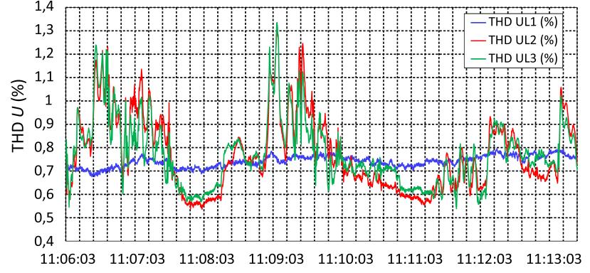
37 Measurements at 110 kv level


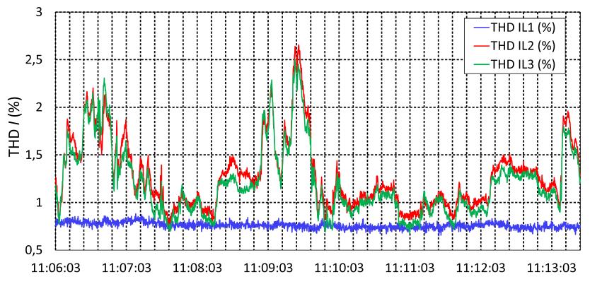
38 Measurements at 25 kv level

39 Influence of the electric railway system on pipelines and telecommunication cables
40 Estimation of return current that flows through rails The distribution of traction current in the contact line system
41 Estimation of return current that flows through rails The part of return current that flows through rails depends on parameters such: train distance from TPS, rail-to-earth conductance, number of rails which conduct the return current, single or double track line, soil resistivity, etc. In the middle part between the traction vehicle and TPS, the return current of about 58.5% flows through rails.
42 Induced Voltages on Underground Pipeline in the Vicinity of the AC Traction System Induced voltages were analyzed on buried pipeline in case of short circuit on the electric traction contact line system. The contact line system and pipeline were modelled using frequency dependent transmission line model in EMTP-RV. The figure shows the part of the corridor with total length of 1.5 km and all distances required for induced voltage calculation.
43 Induced Voltages on Underground Pipeline in the Vicinity of the AC Traction System Induced voltages on the buried pipeline were calculated in case of short circuit on the electric traction contact line system. Pipeline is earthed over the 1 Ω resistance at the both ends. AC current source LINE DATA Contact line FDline1 FD FDline2 FD FDline3 FD FDline4 FD FDline5 FD 5kA /_0 AC1 1 R2 m2 VM?v m3 VM?v m4 VM?v m1 VM?v Pipeline 1 R1 R3

44 Influence of the electric railway system on telecommunication cables Cross-section of the pole of the AC 25 kv single-track and current directions Catenary wire Telecommunication cable Contact wire Rails
45 Measurements and Simulations in Trail Operation of Electric Traction Power Supply After Its Modification Measurement of the induced voltage at the end of the telecommunication cable Measurement of the electric traction current was carried out in a traction substation
46 Measurements and Simulations in Trail Operation of Electric Traction Power Supply After Its Modification a) Current through the electric traction contact conductor; b) Voltage induced at the end of the telecommunication cable
47 Measurements and Simulations in Trail Operation of Electric Traction Power Supply After Its Modification The telecommunication cable was divided into 75 segments in order to determine the mutual inductance. Calculated induced voltage versus the contact line length is shown in Figure. Calculations: 37 V Measurements: 35 V
48 User Group 2016 Aix-en-Provence, France 9 th - 10 th June 2016 MODELLING OF 25 kv ELECTRIC RAILWAY SYSTEM IN EMTP-RV Prof. Ivo Uglešić, PhD Božidar Filipović-Grčić, PhD Faculty of Electrical Engineering and Computing University of Zagreb, Croatia 1
Modeling of 25 kv Electric Railway System for Power Quality Studies
 Modeling of 25 kv Electric Railway System for Power Quality Studies Alan Župan 1, Ana Tomasović Teklić 2, Božidar Filipović-Grčić 3 1 HEP-Transmission System Operator Kupska 4, Zagreb, Croatia alan.zupan@hep.hr
ANALYSIS OF MEASUREMENT AND SIMULATION RESULTS OF FREIGHT TRAIN POWER SUPPLY
 ANALYSIS OF MEASUREMENT AND SIMULATION RESULTS OF FREIGHT TRAIN POWER SUPPLY Milivoj Mandić (1), Viktor Milardić (2), Ivo Uglešić (2), Božidar Filipović-Grčić (2) (1) Croatian Railways Infrastructure (2)
Power Quality Analysis in Electric Traction System with Three-phase Induction Motors
 Power Quality Analysis in Electric Traction System with Three-phase Induction Motors B. Milešević, I. Uglešić, B. Filipović-Grčić Abstract Three-phase induction motors are widely used in electric traction
Study of Fault Clearing by A Circuit Breaker In Presence of A Shunt Capacitor Bank
 Day 2 - Session V-B 299 Study of Fault Clearing by A Circuit Breaker In Presence of A Shunt Capacitor Bank Murali Kandakatla, B. Kondala Rao, Gopal Gajjar ABB Ltd., Maneja, Vadodara, India Thane Introduction
An Alternative to Reduce Medium-Voltage Transient Recovery Voltage Peaks
 An Alternative to Reduce Medium-Voltage Transient Recovery Voltage Peaks D. M. Nobre W. L. A. Neves B. A. de Souza Departamento de Engenharia Elétrica - UFPB Av. Aprígio Veloso, 882 Bodocongó 58.109-970,
Targeted Application of STATCOM Technology in the Distribution Zone
 Targeted Application of STATCOM Technology in the Distribution Zone Christopher J. Lee Senior Power Controls Design Engineer Electrical Distribution Division Mitsubishi Electric Power Products Electric
Shunt Capacitor Bank Protection in UHV Pilot Project. Qing Tian
 Shunt Capacitor Bank Protection in UHV Pilot Project Qing Tian 2012-5 INTRODUCTION State Grid Corp. of China, the largest electric power provider in the country, has first build a 1000 kv transmission
POWER QUALITY SEMINAR OF IRAN, 2 ND MARCH 2017 Power Quality Seminar. Abel-Zhang,Power Quality Center Manager
 POWER QUALITY SEMINAR OF IRAN, 2 ND MARCH 2017 Power Quality Seminar Abel-Zhang,Power Quality Center Manager Contents Capacitor Unit Capacitor Shunt Bank Type Solution of Filter March 7, 2017 Slide 2 Contents
Simulated Switching Transients in the External Grid of Walney Offshore Wind Farm
 Downloaded from orbit.dtu.dk on: Apr 07, 2019 Simulated Switching Transients in the External Grid of Walney Offshore Wind Farm Arana Aristi, Iván; Johnsen, D. T.; Soerensen, T.; Holbøll, Joachim Published
Independent Testing Laboratory for High Voltage Equipment
 T E S T I N G L A B O R A T O R Y Independent Testing Laboratory for High Voltage Equipment 1 CHALLENGING ENVIRONMENT The primary concern for utilities is to ensure grid reliability, efficiency, and security.
A study of the power capacity of regenerative inverters in a DC electric railway system
 Energy Management in the Train Operation 35 A study of the power capacity of regenerative inverters in a DC electric railway system C. H. Bae, M. S. Han, Y. K. Kim, S. Y. Kwon & H. J. Park Korea Railroad
Check points for the connection of Capacitor&Reactor
 Application Reactor is used in conjuction with capacitor banks in series. Its main function is to compensative or produce reactive power. According to the purpose of use, reactor helps to limit inrush
6545(Print), ISSN (Online) Volume 4, Issue 2, March April (2013), IAEME & TECHNOLOGY (IJEET)
, ISSN (Online) Volume 4, Issue 2, March April (2013), IAEME & TECHNOLOGY (IJEET)") INTERNATIONAL International Journal of JOURNAL Electrical Engineering OF ELECTRICAL and Technology (IJEET), ENGINEERING ISSN 0976 & TECHNOLOGY (IJEET) ISSN 0976 6545(Print) ISSN 0976 6553(Online) Volume
INTERNATIONAL International Journal of JOURNAL Electrical Engineering OF ELECTRICAL and Technology (IJEET), ENGINEERING ISSN 0976 & TECHNOLOGY (IJEET) ISSN 0976 6545(Print) ISSN 0976 6553(Online) Volume
Unrestricted. Air Core Reactor Applications Current Limiting Reactors
 Unrestricted Air Core Reactor Applications Current Limiting Reactors Faults on Electrical System - Basic Concepts Three major concerns arise from this scenario: 1- The mechanical stresses on the transformer
Research on Transient Stability of Large Scale Onshore Wind Power Transmission via LCC HVDC
 Research on Transient Stability of Large Scale Onshore Wind Power Transmission via LCC HVDC Rong Cai, Mats Andersson, Hailian Xie Corporate Research, Power and Control ABB (China) Ltd. Beijing, China rong.cai@cn.abb.com,
Medium Voltage. Power Factor Correction Reactive Compensation Harmonic Filters. Electrical Power Quality Management at its best.
 Medium Voltage Power Factor Correction Reactive Compensation Harmonic Filters POWER QUALITY Electrical Power Quality Management at its best. From electricity generation, transmission, thru its distribution
Qingdao Zener Electric Co., Ltd
 Traction inverter, Power Supply, Emergency ventilation inverter for Light rail train Qingdao Zener Electric Co., Ltd Part 1 Power Supply for the Overhead Traction Line Introduction Conventional power supply
RURAL ELECTRIFICATION WITH THE SHIELD WIRE SCHEME APPLICATIONS IN DEVELOPING COUNTRIES
 AEI AFRICA ELECTRIFICATION INITIATIVE WORKSHOP IN DAKAR, NOV. 2011 RURAL ELECTRIFICATION WITH THE SHIELD WIRE SCHEME APPLICATIONS IN DEVELOPING COUNTRIES by F. ILICETO University of Rome La Sapienza Rome,
Electrification and Power Supply. Andrea Nardinocchi Technological Design Department Italferr S.p.A., Rome, Italy
 Electrification and Power Supply Andrea Nardinocchi Technological Design Department Italferr S.p.A., Rome, Italy 1 RAILWAY POWER SUPPLY Electrification systems in Europe Electrification design criteria
TSTE25 Power Electronics. Lecture 4 Tomas Jonsson ISY/EKS
 TSTE25 Power Electronics Lecture 4 Tomas Jonsson ISY/EKS 2016-11-09 2 Outline The thyristor Controlled rectifier and inverters Single phase Three phase 2016-11-09 3 Thyristors Only possible to turn on
ABB n.v Power Quality in LV installations
 ABB n.v. - 1 - Power Quality in LV installations PQ problems in LV installations 750 500 250 Volts 0-250 -500 Amps -750 3000 2000 1000 0-1000 -2000-3000 10:25:43.72 10:25:43.73 10:25:43.74 10:25:43.75
POWERSYS Software & Services
 POWERSYS Software & Services Power Systems Transport, Transmission & Distribution Renewable Energy Electrical Equipment www.powersys-solutions.com EXPERT IN POWER SYSTEMS STUDIES WHO IS POWERSYS? Powersys
EMPAC Metal enclosed capacitor bank for wind applications
 EMPAC Metal enclosed capacitor bank for wind applications Introduction The EMPAC is a Metal Enclosed Capacitor Bank suitable for voltages between 1 kv and 36 kv for reactive compensation in MV networks
C1000 Series Automatic Cap Bank
 C1000 Series Automatic Cap Bank Metal Enclosed - Medium Voltage Capacitors Assemblies Fixed / Auto Medium Voltage 5, 15, 25 and 35 kv Class Customized to your specifications The Reactive Power Solution
MODVAR Low voltage reactive power compensation modules Installation manual
 MODVAR Low voltage reactive power compensation modules Installation manual MODVAR Low voltage reactive power compensation modules Before installation, read this manual carefully and keep at the disposal
Latch for Contactors 4-pole see page 36. Ratings Rated Aux. Contacts Type Coil voltage 2) AC2 Current Built-in Additional 24 24V= DC 5
 AC2 Current Built-in Additional 24 24V= DC 5") 3-pole DC Operated Ratings Rated Aux. Contacts Type Coil voltage 1) AC2 Current Built-in Additional 24 24V= DC 5 AC3 see 48 60V= DC 6 380V AC1 page 34 110 110V= DC 7 400V 660V 220 220V= DC 8 415V 690V
3-pole DC Operated Ratings Rated Aux. Contacts Type Coil voltage 1) AC2 Current Built-in Additional 24 24V= DC 5 AC3 see 48 60V= DC 6 380V AC1 page 34 110 110V= DC 7 400V 660V 220 220V= DC 8 415V 690V
ABB POWER SYSTEMS CONSULTING
 ABB POWER SYSTEMS CONSULTING DOMINION VIRGINIA POWER Offshore Wind Interconnection Study 2011-E7406-1 R1 Summary Report Prepared for: DOMINION VIRGINIA POWER Report No.: 2011-E7406-1 R1 Date: 29 February
Air-insulated switchgear UniGear type ZS1
 Air-insulated switchgear UniGear type ZS1 ABB Power Technologies / 1-7074 D 12-03-2003 - Air-insulated switchgear UniGear type ZS1 ABB Power Technologies / 2-7075 D 1 2-03-2003 - Rated voltage kv 12 17.5
HARMONIC FILTER REACTOR
 380V 50Hz Series Resonance Frequency : 204Hz or p = 6% To be used with 415V capacitor only Design : According to VDE 0550/0532 & IEC 76 l 250 = 0.31 x l N Testing : Insulation strength tested at 2.5kV
43-SDMS-04 REV. 00 SPECIFICATIONS FOR
 43-SDMS-04 REV. 00 SPECIFICATIONS FOR SHUNT CAPACITOR BANK 13.8 kv THROUGH 69 kv FOR PRIMARY DISTRIBUTION SUBSTATIONS This specification is property of SEC and subject to change or modification without
CTU 02. Thyristor switching module for fast PF compensation. User manual
 CTU 02 Thyristor switching module for fast PF compensation User manual version 1.3 Czech Republic Czech Republic 1 Content 1. Function description... 3 2. Device description and indication features...
132/11 kv, 25 MVA MOBILE SUBSTATION
 File name: Mob EN katalog1 Zagreb, 11.11.2014. Page: 1 od 9 Summary Mobile substation consists of two semitrailers. One trailer is for 132 kv equipment (HV equipment) and another trailer is for medium
Variable speed control of compressors. ABB drives control the compressors of the world s longest gas export pipeline
 Variable speed control of compressors drives control the compressors of the world s longest gas export pipeline drives power Ormen Lange From 2007, gas from the Ormen Lange offshore gas field will flow
INSTALLATION OF CAPACITOR BANK IN 132/11 KV SUBSTATION FOR PARING DOWN OF LOAD CURRENT
 INSTALLATION OF CAPACITOR BANK IN 132/11 KV SUBSTATION FOR PARING DOWN OF LOAD CURRENT Prof. Chandrashekhar Sakode 1, Vicky R. Khode 2, Harshal R. Malokar 3, Sanket S. Hate 4, Vinay H. Nasre 5, Ashish
Eskisehir Light Train- Correcting Capacitive
 Case Study-Estram Light Train Eskisehir Light Train- Correcting Capacitive Power Factor Eskisehir, a city in the Anatolia region of Turkey is located in an area inhabited since at least 3500 BCE- the copper
CHAPTER 5 FAULT AND HARMONIC ANALYSIS USING PV ARRAY BASED STATCOM
 106 CHAPTER 5 FAULT AND HARMONIC ANALYSIS USING PV ARRAY BASED STATCOM 5.1 INTRODUCTION Inherent characteristics of renewable energy resources cause technical issues not encountered with conventional thermal,
EH2741 Communication and Control in Electric Power Systems Lecture 3. Lars Nordström Course map
 EH2741 Communication and Control in Electric Power Systems Lecture 3 Lars Nordström larsn@ics.kth.se 1 Course map 2 1 Outline 1. Repeating Power System Control 2. Power System Topologies Transmission Grids
Nissin s Products for Electric Railway System
 Ref. No. EKF120927-PRWS Nissin s Products for Electric Railway System KYOTO, JAPAN September, 2012 Introduction of Nissin Electric as Prime Supplier of Equipment for Electric Railway System in Japan Nissin
SINAMICS SM150. Siemens product performance features. Competitor product profile. Components. Power, transport units. Service friendliness
 SINAMICS SM150 B.Rasch A&D LD IB mail to: bjoern.rasch@siemens.com Slides: 1 SINAMICS SM150 Product overview Voltage: Power: Motor: Operation: Output frequency: Topology: Technology: Cooling: Closed-loop
Technical Specifications (In-Cash Procurement)
") IDM UID VLHSLE VERSION CREATED ON / VERSION / STATUS 12 Feb 2018 / 1.2 / Approved EXTERNAL REFERENCE / VERSION Technical Specifications (In-Cash Procurement) Technical Summary for BOP-Group 6 Installation
IDM UID VLHSLE VERSION CREATED ON / VERSION / STATUS 12 Feb 2018 / 1.2 / Approved EXTERNAL REFERENCE / VERSION Technical Specifications (In-Cash Procurement) Technical Summary for BOP-Group 6 Installation
SYSTEM INTEGRATION. Railway and urban transport electrification Energy-efficient and reliable solutions
 SYSTEM INTEGRATION Railway and urban transport electrification Energy-efficient and reliable solutions 2 R A I LWAY & U R B A N T R A N S P O R T E L E C T R I F I C AT I O N S O L U T I O N S ABB s substation
CHAPTER 3 TRANSIENT STABILITY ENHANCEMENT IN A REAL TIME SYSTEM USING STATCOM
 61 CHAPTER 3 TRANSIENT STABILITY ENHANCEMENT IN A REAL TIME SYSTEM USING STATCOM 3.1 INTRODUCTION The modeling of the real time system with STATCOM using MiPower simulation software is presented in this
Welcome. Power Survey International
 Welcome Company profile Established in 1948 Exclusively manufacture capacitor banks and harmonic filters Manufacturer of low and medium voltage products: Power Factor correction system Harmonic Filter
Dynamic Reactive Power Control. By V. R. Kanetkar Full Time Consultant Technical Services at Veretiv Energy Private Limited Thane (West)
") Dynamic Reactive Power Control By V. R. Kanetkar Full Time Consultant Technical Services at Veretiv Energy Private Limited Thane (West) Acknowledgement The author acknowledges with deep gratitude the experience
Dynamic Reactive Power Control By V. R. Kanetkar Full Time Consultant Technical Services at Veretiv Energy Private Limited Thane (West) Acknowledgement The author acknowledges with deep gratitude the experience
Reactive Power Compensation using 12 MVA Capacitor Bank in 132/33 KV Distribution Substation
 Reactive Power Compensation using 12 MVA Capacitor Bank in 132/33 KV Distribution Substation Yogesh U Sabale 1, Vishal U Mundavare 2, Pravin g Pisote 3, Mr. Vishal K Vaidya 4 1, 2, 3, 4 Electrical Engineering
Functions provided by measuring relays in railway equipment
 Functions provided by measuring relays in railway equipment 1-Current relays -Minimum current relays (During normal operation, if the current is present these relays are in operating position and switch
ELECTRIC TRACTION.
 ELECTRIC TRACTION www.koncar.hr MODERNISATION ELECTRIC TRACTION VEHICLES Company KON AR - ELECTRIC VEHICLES Inc. upgrades electric locomotives, electric multiple unit and electric tramcars. Upgrading proceedings
SINAMICS SM150. 4/2 Overview. 4/2 Benefits. 4/2 Design. 4/6 Function. 4/8 Selection and ordering data. 4/8 Options
 /2 Overview /2 Benefits /2 Design /6 Function /8 Selection and ordering data /8 Options Technical data /1 General technical data /15 Control properties /15 Ambient conditions /16 Installation conditions
KYN28A-12 (GZS1) A.C METALCLAD REMOVABLE SWITCHGEAR FOR INDOOR USE CHINATCS
 A.C METALCLAD REMOVABLE SWITCHGEAR FOR INDOOR USE CHINATCS") KYN28A-12 (GZS1) A.C METALCLAD REMOVABLE SWITCHGEAR FOR INDOOR USE CHINATCS 2001.09 KYN28A-12 (GZS1) A.C Metalclad Removable Switchgear for Indoor Use --------The Leader in Switchgear Up to 12kV 1. The
KYN28A-12 (GZS1) A.C METALCLAD REMOVABLE SWITCHGEAR FOR INDOOR USE CHINATCS 2001.09 KYN28A-12 (GZS1) A.C Metalclad Removable Switchgear for Indoor Use --------The Leader in Switchgear Up to 12kV 1. The
ABB Wind Power Solution
 Feng Li, Wind ISI, CNABB, November, 2016 ABB Wind Power Solution November 13, 2016 Slide 1 ABB deliveries from A to Z into the wind industry Wind power generation, transmission and integration, control
Industrial Static Var Compensators
 Industrial Static Var Compensators ČKD ELEKTROTECHNIKA - Company profile ČKD ELEKTROTECHNIKA, a.s., a member of ČKD GROUP, has a long term tradition in development and production of electrical equipment,
8. Filter / Autoranging Rectifier Module (FARM )
") Maxi, Mini, Micro Family DC-DC s and Configurable Power Supplies The Filter / Autoranging Rectifier Module (FARM provides an effective solution for the AC front end of a power supply built with converters.
Maxi, Mini, Micro Family DC-DC s and Configurable Power Supplies The Filter / Autoranging Rectifier Module (FARM provides an effective solution for the AC front end of a power supply built with converters.
Three Phase Capacitors KNK
 Three Phase Capacitors KNK Features Connection profile Φ 90 and 116 mm 2-16 mm 2, Φ 136 mm 2-25 mm 2 *Use of flexible conductors only with ferrules Capacitors equipped with discharge resistors Rated power
Wind Power Plants with VSC Based STATCOM in PSCAD/EMTDC Environment
 2012 2nd International Conference on Power and Energy Systems (ICPES 2012) IPCSIT vol. 56 (2012) (2012) IACSIT Press, Singapore DOI: 10.7763/IPCSIT.2012.V56.2 Wind Power Plants with VSC Based STATCOM in
Features. LED Driver. RACT09 9 Watt. TRIAC Dimmable. Single Output RACT09- AC/DC Converter
 Features TRIAC Dimmable LED Driver Triac dimmable with leading or trailing edge dimmers Class II with SELV output (no earth required) Extra-large screw terminals and integrated cable clamps for easy installation
HV Compensation & Filtering Products
 GE Grid Solutions HV Compensation & Filtering Products Providing Power Quality and Energy Efficiency High Voltage (HV) reactive power compensation and harmonic filtering solutions help customers to improve
Performance Analysis of 3-Ø Self-Excited Induction Generator with Rectifier Load
 Performance Analysis of 3-Ø Self-Excited Induction Generator with Rectifier Load,,, ABSTRACT- In this paper the steady-state analysis of self excited induction generator is presented and a method to calculate
Contactor Catalogue. According to CE, IEC 947, EN Pole & 4 Pole Contactors 4kW - 160kW Thermal Overload
 According to CE, IEC 947, EN 60947 Contactor Catalogue 3 Pole & 4 Pole Contactors 4kW - 160kW Thermal Overload Mini-Contactors 4kW - 5.5kW DC Contactors Mini-Relays 10A Motor Starter DOL, Star-Delta Capacitor
Final Draft Report. Assessment Summary. Hydro One Networks Inc. Longlac TS: Refurbish 115/44 kv, 25/33/ General Description
 Final Draft Report Assessment Summary Hydro One Networks Inc. : Refurbish 115/44 kv, 25/33/42 MVA DESN Station CAA ID Number: 2007-EX360 1.0 General Description Hydro One is proposing to replace the existing
Enhancement of Power Quality in Transmission Line Using Flexible Ac Transmission System
 Enhancement of Power Quality in Transmission Line Using Flexible Ac Transmission System Raju Pandey, A. K. Kori Abstract FACTS devices can be added to power transmission and distribution systems at appropriate
ABB FACTS Grid connection of Wind Farms
 Christian PAYERL ABB FACTS Grid connection of Wind Farms May 28, 2010 Slide 1 ABB Power of Wind May 28, 2010 Slide 2 ABB FACTS 300 engineers, highly skilled in the following disciplines: Development Marketing
First Applications on AltaLink s Network. Roggero Ciofani, P. Eng. Colin Clark, P. Eng.
 First Applications on AltaLink s Network Roggero Ciofani, P. Eng. Colin Clark, P. Eng. Overview Technology Overview Applications and Alternatives Advantages Alberta Special Considerations Operational Implications
Experience on Technical Solutions for Grid Integration of Offshore Windfarms
 Experience on Technical Solutions for Grid Integration of Offshore Windfarms Liangzhong Yao Programme Manager AREVA T&D Technology Centre 18 June 2007, DTI Conference Centre, London Agenda The 90MW Barrow
AC/DC FFE converter power module
 Sheet 1 PRODUCT DESCRIPTION The converter series FFE (Fundamental Front End) consists of a three-phase IGBT bridge working at mains frequency and works as rectifier/regenerative bridge allowing the flow
Sr. No. Details Page No. 1 MV Capacitor Unit Drawings 3. 2 Technical Perticular for Capacitor Unit 4. 3 MV Surge Capacitor Unit Drawings 6
 INDEX : Sr. No. Details Page No. 1 MV Capacitor Unit Drawings 3 2 Technical Perticular for Capacitor Unit 4 3 MV Surge Capacitor Unit Drawings 6 4 Technical Perticular for Surge Capacitor Unit 7 5 MV Energy
POWER DISTRIBUTION SYSTEM ANALYSIS OF URBAN ELECTRIFIED RAILWAYS
 POWER DISTRIBUTION SYSTEM ANALYSIS OF URBAN ELECTRIFIED RAILWAYS Farhad Shahnia Saeed Tizghadam Seyed Hossein Hosseini farhadshahnia@yahoo.com s_tizghadam@yahoo.com hosseini@tabrizu.ac.ir Electrical and
Ukujima Photovoltaic Park 400 MW Stable Integration of a 400MW Photovoltaic Farm into the Japanese Power System Challenges and Chances
 Ukujima Photovoltaic Park 400 MW Stable Integration of a 400MW Photovoltaic Farm into the Japanese Power System Challenges and Chances 29 Juli 2014 Page 1 Characteristics of the Project Parameter Detail
MV capacitors banks and accessories
 Power factor correction and harmonic filtering 8 R. /9 MV capacitors banks and accessories R. 8 /9 MV capacitors banks and accessories Introduction R8/9-3 R.8 - MV capacitors and accessories CHV-M Single-phase
Paper ID: EE19 SIMULATION OF REAL AND REACTIVE POWER FLOW ASSESSMENT WITH FACTS CONNECTED TO A SINGLE TRANSMISSION LINE
 SIMULATION OF REAL AND REACTIVE POWER FLOW ASSESSMENT WITH FACTS CONNECTED TO A SINGLE TRANSMISSION LINE Prof. Mrs. Shrunkhala G. Khadilkar Department of Electrical Engineering Gokhale Education Society.
Schedules 1 to 4, Lot B: Extension of the Lessos Substation
 1.0 LIGHTNING ARRESTORS 1.1 ZNO lightning arrester, 192 kv rated voltage, 10 ka nominal discharge current 2.0 CAPACITIVE VOLTAGE TRANSFORMER ea. 45 2.1 220 kv capacitive voltage transformer 220/ 3 / 0.11/
Power Quality and Power Interruption Enhancement by Universal Power Quality Conditioning System with Storage Device
 Australian Journal of Basic and Applied Sciences, 5(9): 1180-1187, 2011 ISSN 1991-8178 Power Quality and Power Interruption Enhancement by Universal Power Quality Conditioning System with Storage Device
A Transient Free Novel Control Technique for Reactive Power Compensation using Thyristor Switched Capacitor
 A Transient Free Novel Control Technique for Reactive Power Compensation using Thyristor Switched Capacitor 1 Chaudhari Krunal R, 2 Prof. Rajesh Prasad 1 PG Student, 2 Assistant Professor, Electrical Engineering
Qualification of DHS50A,100A to Railway applications. (General Standard EN50155) (Shock and Vibration Standard EN61373)
 (Shock and Vibration Standard EN61373)") Qualification of DHS50A,100A to Railway applications (General Standard EN50155) (Shock and Vibration Standard EN61373) Qualification to Railway applications Contents 1. Purpose 2. Scope 3. Qualification
Qualification of DHS50A,100A to Railway applications (General Standard EN50155) (Shock and Vibration Standard EN61373) Qualification to Railway applications Contents 1. Purpose 2. Scope 3. Qualification
Advanced Protective Relay Training
 Advanced Protective Relay Training Contact us Today for a FREE quotation to deliver this course at your company?s location. https://www.electricityforum.com/onsite-training-rfq A properly designed protection
R.4. Automatic capacitor banks with static system. Power factor correction and harmonic filtering. Homepage :
 R.4 Power factor correction and harmonic filtering Automatic capacitor banks with static system Mail: Hberk@circutor-nrw.de Homepage : www.berk-iv.de Kontakt: Berk Industrievertretung 51103 Köln Erna Schaeffler
2 x 25 kv ac / 1 x 25 kv ac Grounding and Bonding
 2 x 25 kv ac / 1 x 25 kv ac Grounding and Bonding By George Ardavanis, PhD Keywords: overhead catenary system (OCS), electric multiple unit (EMU), grounding and bonding (G&B), overhead contact line (OCL),
Introduction of power electronics in traction power supply fixed installations
 Introduction of power electronics in traction power supply fixed installations C. COURTOIS, E. CARPENTIER SNCF French Railways Infrastructure s Engineering Headquarters, St-Denis Paris, FRANCE Abstract
MYRON ZUCKER CALMANUAL POWER FACTOR CORRECTION APPLICATION GUIDE INC.
 MYRON ZUCKER CALMANUAL POWER FACTOR CORRECTION APPLICATION GUIDE INC. CALMANUAL HOW TO APPLY CAPACITORS TO LOW VOLTAGE POWER SYSTEMS. SECTION INDEX SECTION I POWER FACTOR UNDERSTANDING POWER FACTOR...
Very high efficiency up to 93% Adjustable output voltage
 The Bel Power Solutions 700DNC40-24-xG is a 4 kw DC/DC converter that creates DC voltages in hybrid and electric vehicles necessary to power low voltage accessories. Liquid or convection cooled DC/DC converter
Switchgear and Distribution Systems for Engineers and Technicians
 Switchgear and Distribution Systems for Engineers and Technicians WHAT YOU WILL LEARN: How to identify typical characteristics of an industrial distribution system Become familiar with the main components
AIR CORE REACTORS. Phoenix Electric Corporation
 AIR CORE REACTORS Phoenix Electric Corporation PHOENIX ELECTRIC CORPORATION designs and manufactures Dry Type Air Core Reactors for operation on systems rated through 800 kv. All reactors are custom designed
Comparative Analysis of Integrating WECS with PMSG and DFIG Models connected to Power Grid Pertaining to Different Faults
 IOSR Journal of Electrical and Electronics Engineering (IOSR-JEEE) e-issn: 2278-1676,p-ISSN: 2320-3331, Volume 12, Issue 3 Ver. II (May June 2017), PP 124-129 www.iosrjournals.org Comparative Analysis
Analysis of Grid Connected Solar Farm in ETAP Software
 ABSTRACT 2017 IJSRSET Volume 3 Issue 3 Print ISSN: 2395-1990 Online ISSN : 2394-4099 Themed Section: Engineering and Technology Analysis of Grid Connected Solar Farm in ETAP Software Komal B. Patil, Prof.
LV Capacitor CLMD03 Power Module Instruction manual
 LV Capacitor CLMD03 Power Module Instruction manual Table of Contents 1 Safety... 3 2 Upon reception... 3 2.1 Inspection on reception... 3 2.2 Storage- transportation handling... 3 3 Hardware Description...
IJRASET 2013: All Rights are Reserved
 Power Factor Correction by Implementation of Reactive Power Compensation Methods of 220 KV Substation MPPTCL Narsinghpur Ria Banerjee 1, Prof. Ashish Kumar Couksey 2 1 Department of Energy Technology,
Modular Capacitor Systems Reactive Compen. sation. Copyright 2002 ABB. All rights reserved.
 Modular Capacitor Systems Reactive Compen sation Copyright 2002 ABB. All rights reserved. 12/12/2002 Needs Customer A solution to suit Modular Substations Relocatable assets More value for money ABB A
Approved Standards. Motor Contactor. Main contactor. Accessoires. 21 Motor Contactor J7KN
 Motor Contactor Main contactor AC & DC operated Integrated auxiliary contacts Screw fixing and snap fitting (35 mm DIN rail) up to 45 kw Range from 4 to 110 kw (AC 3, 380/415V) Finger proof ( VBG 4) Accessoires
ELECTRIC SHIP TECHNOLOGY SYMPOSIUM EXPERIMENTAL TESTBED TO DE-RISK THE NAVY ADVANCED DEVELOPMENT MODEL
 ELECTRIC SHIP TECHNOLOGY SYMPOSIUM EXPERIMENTAL TESTBED TO DE-RISK THE NAVY ADVANCED DEVELOPMENT MODEL Shannon Strank Center for Electromechanics The University of Texas at Austin 8/16/2017 CEM Microgrid
FUSES FOR SEMICONDUCTORS
 FUSES FOR SEMICONDUCTORS. POWER SEMICONDUCTORS.. Three families of power semiconductors.. Power semiconductors history.3. Current conversion: one application of the power semiconductors.4. Power semiconductors
Dynamic Reactive Power Control for Wind Power Plants
 Dynamic Reactive Power Control for Wind Power Plants Ernst Camm, Charles Edwards, Ken Mattern, Stephen Williams S&C Electric Company, 6601 N. Ridge Blvd, Chicago IL 60626 USA ecamm@sandc.com, cedwards@sandc.om,
Power Quality. Power Factor Wiring and Service. Background. Introduction. bchydro.com
 Power Quality Power Factor Wiring and Service Scope Power factor is a major consideration in efficient building or system operation. It is the measure of how effectively your equipment is converting electric
SIMULATION ANALYSIS OF STATIC VAR COMPENSATOR BASED ON THE MATLAB/SIMLINK
 th May 3. Vol. 5 No. 5-3 JATIT & LLS. All rights reserved. ISSN: 99-865 www.jatit.org E-ISSN: 87-395 SIMULATION ANALYSIS OF STATIC VAR COMPENSATOR BASED ON THE MATLAB/SIMLINK YANZHOU SUN, LINLIN WEI School
Surabaya Seminar Ferdinand Sibarani, Surabaya, 30 th October Power Quality
 Surabaya Seminar 2014 Ferdinand Sibarani, Surabaya, 30 th October 2014 Power Quality Content 1. Power quality problems 2. ABB s low voltage (LV) solution PCS100 AVC (Active Voltage Conditioner) PCS100
EPRI HVDC Research. Gary Sibilant, EPRI. August 30, 2011
 EPRI HVDC Research John Chan, Ram Adapa, Bernie Clairmont & Gary Sibilant, EPRI EPRI HVDC & FACTS Conference August 30, 2011 Presentation Contents 1. Team Members 2. Research Program Objective & Scope
Increasing Wanzhou Power Transfer Capability by 550kV Fixed Series Capacitor FSC Fengjie
 1 Increasing Wanzhou Power Transfer Capability by 550kV Fixed Series Capacitor FSC Fengjie Lutz Kirschner, Quan Bailu, Ding Yansheng, Wang Zuli, Zhou Yan, Karl Uecker Abstract-- In summer of 2005 the Fengjie
Power factor correction and harmonic filtering. MV capacitors banks and accessories
 Power factor correction and harmonic filtering MV capacitors banks and accessories MV capacitors banks and accessories Introduction R8/9-3 R.8 - MV capacitors and accessories CHV-M Single-phase capacitor
Possibilities of Distributed Generation Simulations Using by MATLAB
 Possibilities of Distributed Generation Simulations Using by MATLAB Martin Kanálik, František Lizák ABSTRACT Distributed sources such as wind generators are becoming very imported part of power system
CHAPTER 6 POWER QUALITY IMPROVEMENT OF SCIG IN WIND FARM USING STATCOM WITH SUPERCAPACITOR
 120 CHAPTER 6 POWER QUALITY IMPROVEMENT OF SCIG IN WIND FARM USING STATCOM WITH SUPERCAPACITOR 6.1 INTRODUCTION For a long time, SCIG has been the most used generator type for wind turbines because of
Switching Power Supplies
 , 18 150 Watt Features Compact boxed power supplies with screw terminal block Universal input 85-264 VAC, 50/60 Hz Short circuit and overvoltage protection High efficiency International safety approvals
Electrical Handbook Fault Calculations Using The Mva Method
 Electrical Handbook Fault Calculations Using The Mva Method In the power systems analysis field of electrical engineering, a per-unit system is the Calculations are simplified because quantities expressed