Grounding Of Standby & Emergency Power Systems
|
|
|
- Marcus Butler
- 5 years ago
- Views:
Transcription
1
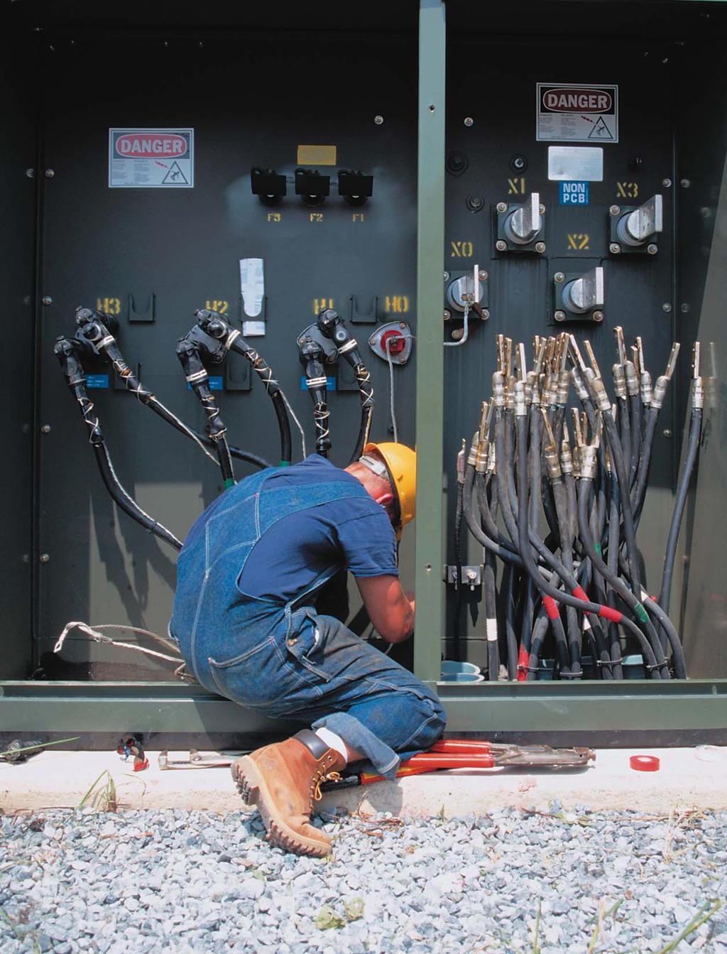
2 July / August 2007 ELECTRICAL LINE 53 Grounding Of Standby & Emergency Power Systems By Andrew Cochran Power continuity is essential in many industrial and commercial installations where a trip out due to ground fault can have serious economic or operational consequences. An arcing phase to ground fault can pose a flash hazard to the maintenance worker close to the fault and can totally destroy the equipment. Consequential down time adds to the economic loss. Four typical grounding methods for standby generators and emergency power systems are examined for these factors and the paper concludes that high resistance grounding provides the best power continuity, the best protection against arcing ground fault damage in low voltage distribution systems (up to 1000V) and improves reliability and availability of standby and emergency power systems Standby and emergency systems are often configured to provide 600 V or 480 V, 3-phase 4-wire service and are thus solidly grounded. In solidly grounded systems the ground fault currents are very high and damaging and circuit protective devices have to operate to isolate the faulty circuit and interrupt the supply. This even applies to the emergency or standby system such as a fire pump where the faulted circuit is tripped and the system de-energized, with potentially disastrous consequences if there were no power during an emergency. Benefits Of Proper System Grounding System grounding the intentional connection of the neutral points of transformers, generators and rotating machinery to the earth ground network provides a reference point of zero volts, which offers many advantages over an ungrounded system, including: Reduced magnitude of transient over-voltages Simplified ground fault location Improved system and equipment fault protection Reduced maintenance time and expense Greater safety for personnel Improved lightning protection Reduction in frequency of faults. Solidly Neutral Grounded Systems Offer Partial Protection In a solidly grounded system, the neutral points have been intentionally connected to ground with a conductor having no intentional impedance. This reduces the problem of transient over-voltages found on the ungrounded system and speeds the location of faults. However, solidly grounded systems lack the current-limiting ability of resistance grounding and the extra protection this provides against equipment damage and arcing ground faults. The well-documented destructive nature of arcing ground faults in solidly grounded systems is caused by the energy dissipated in the fault. The faulted circuits need to be tripped and with conventional time-current coordination often it is difficult to selectively trip the circuit with minimum time delay resulting in extensive equipment damage. Advantages Of Resistance Grounded Neutral Systems Resistance grounding is by far the most effective and preferred method. It solves the problem of transient over-voltages and reduces equipment damage. It accomplishes this by allowing the magnitude of the fault current to be predetermined and limited by a simple Ohms law calculation: I = E/R Where: I = Limit of fault current. E = Line-to-neutral voltage of system R = Ohmic value of neutral grounding resistor In addition, limiting fault currents to predetermined maximum values permits the designer to selectively co-ordinate the operation of protective devices that minimizes system disruption and allows quick location of the fault. High resistance grounding can be applied on distribution systems up to 5KV with low resistance grounding recommended at voltages between 15 and 36KV. Utility systems
.")
3 54 ELECTRICAL LINE July / August 2007 are usually solidly grounded, but on the secondary side of the supply transformer on the customer premises the grounding system is independent and full advantage can be taken of the benefits provided by high resistance grounding. High-resistance grounding of the neutral limits the ground fault current to a very low level (typically under 25 amps). It is used on low-voltage systems of 600 volts or less, under 3000 amps. By limiting the ground fault current, the fault can be tolerated on the system until it can be located, and then isolated or removed at a convenient time. This permits continued production, provided a second ground fault does not occur. High-resistance neutral grounding can be added to existing ungrounded systems without the expense of adding fault clearing relays and breakers. This provides an economical method of upgrading older, ungrounded systems. The resistor must be sized to ensure that the ground fault current is greater than the system s total capacitance-to-ground charging current. If not, then transient over-voltages can occur. By strategic use and location of ground fault sensing relays, troubleshooting can be greatly simplified. High-resistance neutral grounding combined with sensitive ground fault relays and isolating devices, can quickly detect and shut down the faulted circuit. This provides operating personnel with the added safety that s essential in today s operating environments. Another major advantage is the elimination of dangerous and destructive flashovers to ground, which can occur on solidly grounded systems. Grounding Of Standby Generators In 3-Phase 4-Wire Systems In most large commercial buildings and industrial installations, generators are used for standby power or for emergency. So when the distribution includes a distributed neutral then by the electrical Code it must be solidly grounded. There are three ways in which this can be integrated: 1. Each generator neutral is independently grounded and the neutrals are connected together with the normal source neutral that is also grounded and then distributed. 2. Generator neutrals are connected and grounded at one location. Normal supply neutral is also grounded and the common neutral is distributed 3. The generator common neutral is connected to the normal supply neutral and is grounded only at one location. In all of the above the ground fault current has multiple paths through the ground and the neutral conductor to return to the source. Sensing ground fault current becomes very difficult and may cause nuisance tripping, or ground faults may not be sensed at all. Automatic Transfer Switches Automatic transfer switches are used to supply the emergency load. Four wire system necessitates the use of four pole devices with or without an overlapping neutral. The ground fault protection and coordination becomes difficult and complex. Changing the distribution to three wires overcomes this. The Power of ONE Minutes ago, this city lost power. We didn t notice. Finning Power Systems Your ONE Call For: Generator Sets Switchgear Caterpillar Flywheel UPS Preventative Maintenance finning finning.ca Circle 38 on Reader Service Card


4 ASCO: your partner in power. the expertise to meet all your power challenges: issues like high summer demand for electricity and risks to the environment. By using high-technology R EMIS ASCO recently put a solution like this to work for Toronto Hydro, to meet consumersõ needs during summer afternoons when electricity demand and costs are at their peak. By fueling an ASCO power switch with used cooking il T t H d h t ti f and a switch that could work for you, too. Network Power Circle 39 on Reader Service Card


5 56 ELECTRICAL LINE July / August 2007 Connecting standby or emergency supply in a 3 phase 3-wire systems only requires 3 pole transfer switches, whereas four-wire distribution systems with the sources independently grounded require four pole transfer switches. In multiple source distribution schemes where single grounding location of the neutral is used, the application of ground fault protection becomes very complex and very expensive. False tripping can occur if circulating load neutral currents and the returning ground fault current are not properly sensed. Solidly Grounded Systems To High Resistance Grounding In most large commercial and industrial distribution systems at 600V the single-phase 347V load is very limited (mostly the high voltage lighting). The load is essentially 3 phase motors and transformers and therefore conversion of 3 phase 4 wire to 3 phase 3 wire is entirely practical and feasible. If the neutral is not distributed it can be impedance grounded. Only 3 pole transfer switches are used. Small lighting transformers are used for the 347/600 V or 120/208 V distribution to service single phase loads. Figure 1 shows a typical arrangement. The generator bus is grounded through an artificial neutral and the normal supply transformer neutral is grounded through high resistance. A 3-pole automatic transfer switch feeds the essential load. Only alarm and indication of ground fault is required and no tripping occurs in the main and standby switchboards. Fire pumps are usually 3 wire loads and conversion to 3-wire distribution becomes an easy retrofit for existing installations. This concept is being retrofitted in a high-rise office tower in downtown Toronto. The two 1750KVA generators will be converted to high resistance grounding. A ground alarm relay will alarm to the building management system on the occurrence of a ground fault The maintenance electrician will then be able to find the faulty circuit by tracing a pulsing ground current using a hand held multimeter while the system remains energized and working. The rest of the supply distribution will remain unaffected and is 3-phase 4- wire solidly grounded. Summary Ungrounded delta systems have many operating disadvantages including high transient over-voltages and difficulty in locating faults. Solidly grounded neutral systems provide greater safety for personnel, limit the system potential to ground, and speed the detection and location of the ground fault. However, the system must be shut down after the first ground fault. Applying coordinated ground fault protection is very difficult and almost impossible with multiple sources and standby generators. Low-resistance grounded neutral Standby Generator Figure 1 Essential Load 3Φ / 3W ATS systems only limit the magnitude of the ground fault current so that serious damage does not occur. The system must still be shut down after the first ground fault. This level of resistance grounding is generally used on medium and high-voltage systems. If the power system is changed to resistance grounding then the ground fault current can be reduced to 10A or less which has significant impact on reducing the fire risk and equipment damage. In addition it ensures that standby power and emergency power systems continue to operate and do not suffer tripout of a faulted feeder. Andrew Cochran is President of I-Gard Corporation in Mississauga, Ontario. Circle 40 on Reader Service Card R 3Φ / 3W 4 Wire Loads Normal Load Motor, Drive & Control Power Quality Power Distribution Power Quality Diagnosis Engineering Installation Beaver provides a complete package of for many types of Power Quality problems. Power Factor Correction Harmonic Filtering Surge Suppression UPS Systems Power Quality Monitoring Systems Now stocking GE UPS Systems Beaver Electrical Machinery Ltd. Burnaby T. (604) F. (604) Prince George (Field) T. (250) F. (250) Prince George (Shop) T. (250) F. (250) Nanoose Bay T. (250) F. (250) Campbell River T. (250) F. (250) HR SERVICE Circle 41 on Reader Service Card
DESIGN CONSIDERATIONS FOR APPLICATION OF SHUNT CAPACITORS IN HEAVY HATER PLANT (TUTICORIN)
") DESIGN CONSIDERATIONS FOR APPLICATION OF SHUNT CAPACITORS IN HEAVY HATER PLANT (TUTICORIN) -A.R. Subraaanian -R.A.A. Palani -J. Thomson A new 3.3 K.V. 4200 KVAR auto switching capacitor bank has been installed
DESIGN CONSIDERATIONS FOR APPLICATION OF SHUNT CAPACITORS IN HEAVY HATER PLANT (TUTICORIN) -A.R. Subraaanian -R.A.A. Palani -J. Thomson A new 3.3 K.V. 4200 KVAR auto switching capacitor bank has been installed
9/16/2010. Chapter , The McGraw-Hill Companies, Inc. TRANSMISSION SYSTEMS. 2010, The McGraw-Hill Companies, Inc.
 Chapter 3 TRANSMISSION SYSTEMS 1 Transmitting large amounts of electric energy over long distances is accomplished most efficiently by using high-voltages. Without transformers the widespread distribution
Outdoor Distribution (15 kv through 25 kv) S&C Fault Tamer Fuse Limiter
 S&C Fault Tamer Fuse Limiter") Outdoor Distribution (5 kv through 25 kv) S&C Fault Tamer Fuse Limiter Introducing S&C s new generation of pole-top transformer protection... Application Although the S&C Fault Tamer Fuse Limiter handles
Outdoor Distribution (5 kv through 25 kv) S&C Fault Tamer Fuse Limiter Introducing S&C s new generation of pole-top transformer protection... Application Although the S&C Fault Tamer Fuse Limiter handles
Technical information No. 01. IT systems. The basis for reliable power supply
 IT systems The basis for reliable power supply FA01en/01.2004 IT systems The basis for reliable power supply in critical areas The advantages of sophisticated industrial systems can only be of use, if
2000 Cooper Bussmann, Inc. Page 1 of 9 10/04/00
 DO YOU KNOW THE FACTS ABOUT SINGLE-POLE INTERRUPTING RATINGS? YOU MAY BE IN TROUBLE! Typical plant electrical systems use three-phase distribution schemes. As an industry practice, short-circuit calculations
Design Considerations to Enhance Safety and Reliability for Service Entrance Switchboards
 Design Considerations to Enhance Safety and Reliability for Service Entrance Switchboards Robert P. Hansen, P.E., PhD GE Specification Engineer Introduction Switchboards are a widely used type of equipment
Design considerations for generator set mounted paralleling breakers
 Our energy working for you. Design considerations for generator set mounted paralleling breakers White Paper Hassan Obeid, Application Group Cummins Power Generation Cummins Power Systems has been delivering
Grounding Systems. Resistance. Resistance Grounding Systems Contents
 Resistance Systems.0-1 Resistance Systems Contents Resistance Systems High Resistance System Medium Voltage...............1-1 High Resistance System Low Voltage..................2-1 Specifications See
S&C Fault Tamer Fuse Limiter. Outdoor Distribution (15 kv through 25 kv)
") S&C Fault Tamer Fuse Limiter Outdoor Distribution (5 kv through 25 kv) Introducing S&C s new generation of pole-top transformer protection... Application Although the S&C Fault Tamer Fuse Limiter handles
S&C Fault Tamer Fuse Limiter Outdoor Distribution (5 kv through 25 kv) Introducing S&C s new generation of pole-top transformer protection... Application Although the S&C Fault Tamer Fuse Limiter handles
EE 741 Over-voltage and Overcurrent. Spring 2014
 EE 741 Over-voltage and Overcurrent Protection Spring 2014 Causes of Over-voltages Lightning Capacitor switching Faults (where interruption occurs prior to zero current crossing) Accidental contact with
The University of New South Wales. School of Electrical Engineering and Telecommunications. Industrial and Commercial Power Systems Topic 6
 The University of New South Wales School of Electrical Engineering and Telecommunications Industrial and Commercial Power Systems Topic 6 PROTECTIONS 1 FUNCTION OF ELECTRICAL PROTECTION SYSTEMS Problems:
White Paper. Ground Fault Application Guide. WL Low Voltage Power Circuit Breakers
 White Paper Ground Fault Application Guide WL Low Voltage Power Circuit Breakers Table of Contents Introduction 3 Need for ground fault tripping 3 Requirements from industry standards 3 National Electrical
SDC,Inc. SCR-Regenerative Ac Drive
 SDC,Inc WWW.STEVENSDRIVES.COM APPLICATION NOTE #: AN_REG_GEN000 EFFECTIVE DATE: 12 MAR 02 SUPERSEDES DATE: Original NO. OF PAGES: 10 SCR-Regenerative Ac Drive Using a regeneration controller with adjustable-frequency
Switchgear and Distribution Systems for Engineers and Technicians
 Switchgear and Distribution Systems for Engineers and Technicians WHAT YOU WILL LEARN: How to identify typical characteristics of an industrial distribution system Become familiar with the main components
The Case for Hybrid Generator Grounding
 I-Gard Hybrid Generator Whitepaper 1 The Case for Hybrid Generator Sergio Panetta March 10, 2014 VP of Engineering, I-Gard Medium Voltage Generators are not designed to withstand full fault current during
Chapter 6 Generator-Voltage System
 Chapter 6 Generator-Voltage System 6-1. General The generator-voltage system described in this chapter includes the leads and associated equipment between the generator terminals and the low-voltage terminals
ECET Distribution System Protection. Overcurrent Protection
 ECET 4520 Industrial Distribution Systems, Illumination, and the NEC Distribution System Protection Overcurrent Protection One of the most important aspects of distribution system design is system protection.
TRANSMISSION SYSTEMS
 TRANSMISSION SYSTEMS Transmitting large amounts of electric energy over long distances is accomplished most efficiently by using high-voltages. Without transformers the widespread distribution of electric
Modular Standardized Electrical and Control Solutions for Fast Track Projects
 Modular Standardized Electrical and Control Solutions for Supporting fast track projects ABB is the leading supplier of electrical and control equipment for power plants. The company offers a comprehensive
6/4/2017. Advances in technology to address safety. Thomas A. Domitrovich, P.E., LEED AP VP, Technical Sales Eaton
 Advances in technology to address safety Thomas A. Domitrovich, P.E., LEED AP VP, Technical Sales Eaton 1 Advances in technology could mean use existing technology & back to basics Advances in safety are
RULE 21 GENERATING FACILITY INTERCONNECTION APPLICATION SMUD s Distribution System - (SMUD FORM 2655)
") - (SMUD FORM 2655) A. Applicability: This Generating Facility Interconnection Application (Application) shall be used to request the interconnection of a Generating Facility to Sacramento Municipal Utility
- (SMUD FORM 2655) A. Applicability: This Generating Facility Interconnection Application (Application) shall be used to request the interconnection of a Generating Facility to Sacramento Municipal Utility
IEEE Northern Canada & Southern Alberta Sections, PES/IAS Joint Chapter Technical Seminar Series
 IEEE Northern Canada & Southern Alberta Sections, PES/IAS Joint Chapter Technical Seminar Series Designing Electrical Systems for On-Site Power Generation Apr 04 th /05 th, 2016, Calgary/Edmonton, Alberta,
Service Entrance Methods
 Service Section Typical switchboards consist of a service section, also referred to as the main section, and one or more distribution sections. The service section can be fed directly from the utility
Arc-Flash Mitigation Technologies. Dennis Balickie
 Arc-Flash Mitigation Technologies Dennis Balickie The purpose of the session is to provide an overall understanding of the strategic impact of arc-flash. Special focus is on the tactical means to minimize
Are the New 2005 NEC Selective Coordination Requirements Causing an Increase in Arc Flash Energies and Reducing Distribution System Reliability?
 Are the New 2005 NEC Selective Coordination Requirements Causing an Increase in Arc Flash Energies and Reducing Distribution System Reliability? The 2005 NEC has new sections that require people transporting
Digitrip Retrofit System for ITE K-3000, K-3000 S, K-4000 and K-4000 S Breakers
 Supersedes IL 33-858-4 Dated 05/02 Digitrip Retrofit System for ITE K-3000, K-3000 S, K-4000 and K-4000 S Breakers Digitrip Retrofit System for ITE K-3000, Digitrip Retrofit System for ITE K-3000, K-3000
Medium Voltage. Power Factor Correction Reactive Compensation Harmonic Filters. Electrical Power Quality Management at its best.
 Medium Voltage Power Factor Correction Reactive Compensation Harmonic Filters POWER QUALITY Electrical Power Quality Management at its best. From electricity generation, transmission, thru its distribution
Selective Coordination
 Circuit Breaker Curves The following curve illustrates a typical thermal magnetic molded case circuit breaker curve with an overload region and an instantaneous trip region (two instantaneous trip settings
TERMS AND DEFINITIONS
 Application Guide Adjustable Alarm Level A setting on a protection relay at which an LED or an output contact operates to activate a visual or audible alarm. Adjustable Delay A setting on a protection
ENGINE GOVERNING SYSTEMS LSM672 LOAD SHARING MODULE. GOVERNORS AMERICA CORP. 720 Silver Street Agawam, MA , USA MEMBER
 ENGINE GOVERNING SYSTEMS LSM672 LOAD SHARING MODULE MEMBER GOVERNORS AMERICA CORP. 720 Silver Street Agawam, MA 01001-2907, USA LSM672 LOAD SHARING MODULE PRODUCT TECHNICAL INFORMATION PTI 4000 AUGUST
SECTION LOW VOLTAGE DISTRIBUTION EQUIPMENT
 SECTION 16400 LOW VOLTAGE DISTRIBUTION EQUIPMENT A. General 1. The University does not accept Series-Rated equipment for power distribution switchboards, distribution panels and branch circuit panelboards.
A comparison of metal-enclosed load interrupter (ME) switchgear and metal-clad (MC) switchgear
 switchgear and metal-clad (MC) switchgear") Robert J. Gustin Eaton Fellow Application Engineer, P. E. Southfield, Michigan Definitions Metal-enclosed load interrupter switchgear type ME Metal-enclosed switchgear is defined in ANSI C37.20.3-1987,
Robert J. Gustin Eaton Fellow Application Engineer, P. E. Southfield, Michigan Definitions Metal-enclosed load interrupter switchgear type ME Metal-enclosed switchgear is defined in ANSI C37.20.3-1987,
Power Quality and Protective Device Coordination: Problems & Solutions Part 1 Undersizing of Utility Main Service Transformers
 Power Quality and Protective Device Coordination: Problems & Solutions Part 1 Undersizing of Main Service s INTRODUCTION by Robert E. Fuhr, P.E. The use of electronic equipment has dramatically increased
Electromagnetic Industries LLP
 GROUND FAULT CURRENT DETECTION GFM Relay (Model 252 & 262) The GFM system is designed for electrical protection, not for personnel protection Application: These Class 1 (Model GFM) Ground Fault protection
B-03 ELECTRICIAN TRAINING SKILL DEVELOPMENT GUIDE
 B-03 ELECTRICIAN TRAINING SKILL DEVELOPMENT GUIDE Duty B: Power Distribution (600V and below) B-03: Troubleshoot 480V System Issued 06/01/98 Task Preview Troubleshoot 480V System The 480V distribution
Recommended Procedures
 Selective Coordination Study Recommended Procedures The following steps are recommended when conducting a selective coordination study.. One-Line Diagram Obtain the electrical system one-line diagram that
Power & High Voltage Joslyn Hi-Voltage Overhead Reclosers & Switches H-220. Series HVI Hi-Velocity Interrupter Attachment
 Use load interrupter attachments to enable loop sectionalizing, line dropping, load breaking and transformer-magnetizing current interruption. Increase the capability of your disconnect switches by adding
400/230 Volt 60Hz UPS Power
 olt 60Hz Power Using ual Voltage standby generation and in one Nothing protects quite like Piller www.piller.com Contents 1 Abstract...3 2 Introduction...4 3 Alternative Power istribution...6 4 Integrating
Data Bulletin. Ground-Censor Ground-Fault Protection System Type GC Class 931
 Data Bulletin 0931DB0101 July 2001 Cedar Rapids, IA, USA Ground-Censor Ground-Fault Protection System Type GC Class 931 09313063 GT Sensor Shunt Trip of Circuit Interrupter Window Area for Conductors GC
Overcurrent Protection (2014 NEC) (Homestudy)
 (Homestudy)") Overcurrent Protection (2014 NEC) (Homestudy) Oregon Electrical License The key sections of Article 240 will be discussed. Overcurrent protection for panelboards, appliances, motors, motor compressors,
Overcurrent Protection (2014 NEC) (Homestudy) Oregon Electrical License The key sections of Article 240 will be discussed. Overcurrent protection for panelboards, appliances, motors, motor compressors,
UPPCO SERVICE MANUAL
 Revised 01/2015 Section 6 ELECTRIC SERVICE - GENERAL Page 1 of 10 Section 6 Electric Service - General 6-1 Number of Services and Voltages / Meter... 2 6-2 Energy Conversion Factors... 7 6-3 Lightning
How Protection Relays Solve Electrical Problems
 How Protection Relays Solve Electrical Problems Overview / Introduction I. INTRO TO PROTECTION RELAYS What is a protection relay? Inputs and Settings Processes Outputs How do protection relays solve electrical
Zone Selective Interlocking
 Application Paper AP02602002EN Supersedes 08/2003 Zone Selective Interlocking Contents Description.... Page What is Zone Selective Interlocking?... 3 What is the purpose of Zone Selective Interlocking?....3
90.2 Scope. The installation of electrical conductors, equipment and raceways for:
 NEC Generator Primer Rules on the installation of generators and transfer switches 1 90.2 Scope The installation of electrical conductors, equipment and raceways for: public and private premises Conductors
Unified requirements for systems with voltages above 1 kv up to 15 kv
 (1991) (Rev.1 May 2001) (Rev.2 July 2003) (Rev.3 Feb 2015) (Corr.1 June 2018) Unified requirements for systems with voltages above 1 kv up to 15 kv 1. General 1.1 Field of application The following requirements
Net Metering Interconnection Requirements
 Net Metering Interconnection Requirements Customer Generation Capacity Not Exceeding 100 kw Date: 2017-07-01 Version: 1 Revision History Date Rev. Description July 1, 2017 1 Initial Release Newfoundland
Design Standards NEMA
 Design Standards Although several organizations are involved in establishing standards for the design, construction, and application of motor control centers, the primary standards are established by UL,
3.2. Current Limiting Fuses. Contents
 .2 Contents Description Current Limiting Applications................. Voltage Rating.......................... Interrupting Rating....................... Continuous Current Rating................ Fuse
Net Metering Interconnection Requirements. Customer Generation Capacity Not Exceeding 100 kw. Date: Version: 1
 Net Metering Interconnection Requirements Customer Generation Capacity Not Exceeding 100 kw Date: 2017-07-01 Version: 1 Revision History Date Rev. Description July 01, 2017 1 Initial release Newfoundland
A system fault contribution of 750 mva shall be used when determining the required interrupting rating for unit substation equipment.
 General Unit substations shall be 500 kva minimum, 1500 kva maximum unless approved otherwise by the University. For the required configuration of University substations see Standard Electrical Detail
Engineering Dependable Protection
 Electrical Distribution System Engineering Dependable Protection Engineering Dependable Protection - Part II "Selective Coordination of Overcurrent Protective Devices" Table of Contents Page Basic Considerations
Three days training program (Oct 5-7) on. Substation Earthing, Industrial earthing and Neutral earthing. at IEI Mysore, Karnataka India
 on. Substation Earthing, Industrial earthing and Neutral earthing. at IEI Mysore, Karnataka India") Three days training program (Oct 5-7) on Substation Earthing, Industrial earthing and Neutral earthing at IEI Mysore, Karnataka India Training program is helpful for students, Engineers working in Design
Three days training program (Oct 5-7) on Substation Earthing, Industrial earthing and Neutral earthing at IEI Mysore, Karnataka India Training program is helpful for students, Engineers working in Design
Molded Vacuum Reclosers The recloser you want, all in one package. Single- and Three-Phase Molded Vacuum Reclosers, 15 38kV
 The recloser you want, all in one package. Single- and Three-Phase, 15 38kV The need for automated reclosers has never been greater, but many of today s reclosers come with penalties. They weigh too much,
www. ElectricalPartManuals. com Engineering Dependable Protection
 Electrical Distribution System Engineering Dependable Protection Engineering Dependable Protection - Part II "Selective Coordination of Overcurrent Protective Devices" Table of Contents Page Basic Considerations
mgard-10 microprocessor-based relay
 mgard-10 microprocessor-based relay Ground fault relay mgard-10a mgard-10-a1 mgard-10-a2 C-417EM Instruction Manual, March 2015 ABOUT I-GARD I-Gard s commitment to electrical safety provides both industrial
CHAPTER 3. Basic Considerations and Distribution System Layout
 CHAPTER 3 Basic Considerations and Distribution System Layout Utility Load Classifications The electrical power distribution system is that portion of the electrical system that connects the individual
ECET 211 Electric Machines & Controls Lecture 1-3 (Part 2) Electrical Safety in the Workplace Electrical Safety in the Workplace
 Electrical Safety in the Workplace Electrical Safety in the Workplace") ECET 211 Electric Machines & Controls Lecture 1-3 (Part 2) Electrical Safety in the Workplace Text Book: Electric Motors and Control Systems, by Frank D. Petruzella, published by McGraw Hill, 2015. Other
ECET 211 Electric Machines & Controls Lecture 1-3 (Part 2) Electrical Safety in the Workplace Text Book: Electric Motors and Control Systems, by Frank D. Petruzella, published by McGraw Hill, 2015. Other
ELECTRICAL POWER and POWER ELECTRONICS
 Introduction to ELECTRICAL POWER and POWER ELECTRONICS MUKUND R PATEL (cj* CRC Press Taylor & Francis Group Boca Raton London New York CRC Press is an imprint of the Taylor & Francis Croup, an informa
FACT SHEET Standard: Electrical Safety
 What is a Ground Fault Circuit Interrupter? FACT SHEET The ground-fault circuit interrupter, or GFCI, is a fast-acting circuit breaker designed to shut off electric power in the event of a ground-fault
WIRING DESIGN & PROTECTION REQUIREMENTS CHECKLIST
 WIRING DESIGN & PROTECTION REQUIREMENTS CHECKLIST Use & Identification of Grounded and Grounding Conductors YES NO N/A Grounded conductors are identifiable and distinguishable from all other conductors.
Fuses still the best form of overload protection
 Fuses still the best form of overload protection 2001 George Moraitis (Fuseco Pty. Ltd.) Often when I visit people to talk about circuit protection I hear the comments fuses are a thing of the past and
UNIT 3: GENErAL ELECTriCAL SySTEM DiAGNOSiS
 Electrical/Electronic Systems UNIT 3: GENErAL ELECTriCAL SySTEM DiAGNOSiS LESSON 3: TEST electrical circuits I. Types of electrical circuit tests and electrical faults A. Different types of electrical
Working Principle of Earth Leakage Circuit Breaker (ELCB) and Residual Current Device (RCD)
 and Residual Current Device (RCD)") Working Principle of Earth Leakage Circuit Breaker (ELCB) and Residual Current Device (RCD) Schneider Electric RCBO Earth Leakage Circuit Breaker (ELCB) An Earth Leakage Circuit Breaker (ELCB) is a device
Working Principle of Earth Leakage Circuit Breaker (ELCB) and Residual Current Device (RCD) Schneider Electric RCBO Earth Leakage Circuit Breaker (ELCB) An Earth Leakage Circuit Breaker (ELCB) is a device
Development and Operational Advantages of a Solid State Circuit Breaker with Current Limiting
 Development and Operational Advantages of a Solid State Circuit Breaker with Current Limiting Breaker Technology Operational Advantages Development Schedule Dave Richardson, Ph.D.,P.E. Powell Power Electronic
Extra-High-Voltage SF 6 Gas-Insulated Switchgear
 Extra-High-Voltage SF 6 Gas-Insulated Switchgear Shuichi Sugiyama Masahiko Fujita Takahiro Shinohara 1. Introduction Due to location criteria and toughened restrictions on transportation, it has become
AIR COOLED RECTIFIER SPECIFICATION S-50-A
 SPECIFICATIONS AIR COOLED RECTIFIER Spec50a1 5JAN1999 SPECIFICATION S-50-A HIGH VOLTAGE SINGLE TRANSFORMER AIR COOLED RECTIFIER Standard output power range: 250 to 600 volts at 100 to 1,200 amperes TECHNICAL
Dual Power. Protection. Protection
 54 Fault Clearing Systems by Damien Tholomier., AREVA T&D Automation, Canada Dual Power Single Battery What if it? Short circuits and other abnormal power system conditions are very rear, but may result
Electric Motor Controls BOMA Pre-Quiz
 Electric Motor Controls BOMA Pre-Quiz Name: 1. How does a U.P.S. (uninterruptable power supply) work? A. AC rectified to DC batteries then inverted to AC B. Batteries generate DC power C. Generator, batteries,
Safe, fast HV circuit breaker testing with DualGround technology
 Safe, fast HV circuit breaker testing with DualGround technology Substation personnel safety From the earliest days of circuit breaker testing, safety of personnel has been the highest priority. The best
Matrix APAX. 380V-415V 50Hz TECHNICAL REFERENCE MANUAL
 Matrix APAX 380V-415V 50Hz TECHNICAL REFERENCE MANUAL WARNING High Voltage! Only a qualified electrician can carry out the electrical installation of this filter. Quick Reference ❶ Performance Data Pages
Summary of Revision, IEEE C , Guide for Breaker Failure Protection of Power Circuit Breakers
 Summary of Revision, IEEE C37.119-2016, Guide for Breaker Failure Protection of Power Circuit Breakers Kevin Donahoe GE Grid Solutions 2018 Texas A&M Protective Relaying Conference Agenda Introduction
GP/GPA GROUND FAULT PROTECTION
 GP/GPA GROUND FAULT PROTECTION GROUND FAULT PROTECTION C-220EM Instruction Manual, June 2015 ABOUT I-GARD I-Gard s commitment to electrical safety provides both industrial and commercial customers with
Standby Power Systems
 Source: Power Quality in Electrical Systems Chapter 13 Standby Power Systems The term standby power systems describes the equipment interposed between the utility power source and the electrical load to
The Evolution of Arc Fault Circuit Interruption
 51 st IEEE HOLM Conference on Electrical Contacts The Evolution of Arc Fault Circuit Interruption John A. Wafer Electrical Group Eaton Corporation 2003 Eaton Corporation. All rights reserved. 2 Residential
SLOVAK UNIVERSITY OF TECHNOLOGY Faculty of Material Science and Technology in Trnava ELECTRICAL ENGINEERING AND ELECTRONICS.
 SLOVAK UNIVERSITY OF TECHNOLOGY Faculty of Material Science and Technology in Trnava ELECTRICAL ENGINEERING AND ELECTRONICS Róbert Riedlmajer TRNAVA 2007 Unit 14 - Fundamentals of power system protection
Air Circuit Breaker Retrofitting
 Air Circuit Breaker Retrofitting Future proof your protection system with NHP retrofitting services POWER DISTRIBUTION AND PROTECTION NHP Electrical Engineering Products AUS NZ 1300 NHP NHP 0800 NHP NHP
Is Your Factory Power Source Corrupting Your Product Testing? September 2015 Author: Steve Boegle Engineering Group Leader, Behlman Electronics
 Is Your Factory Power Source Corrupting Your Product Testing? September 2015 Author: Steve Boegle Engineering Group Leader, Behlman Electronics Synopsis: This paper describes the use of AC power supplies
Renewable Energy Systems 14
 Renewable Energy Systems 14 Buchla, Kissell, Floyd Chapter Outline The Electric Power Grid 14 Buchla, Kissell, Floyd 14-1 THREE-PHASE AC 14-2 THREE-PHASE TRANSFORMERS 14-3 GRID OVERVIEW 14-4 SMART GRID
INSTRUCTION BOOK SYSTEM 2001 GROUNDING EQUIPMENT FOR FAULT LOCATION. W/ High Resistance Neutral Grounding. for use on
 PCIB-1031 INSTRUCTION BOOK SYSTEM 2001 GROUNDING EQUIPMENT FOR FAULT LOCATION W/ High Resistance Neutral Grounding for use on 480 VOLT 3 PHASE 60HZ UNGROUNDED SYSTEMS WARNING FOLLOW THE SAFETY INSTRUCTIONS
Guidelines for connection of generators:
 Guidelines for connection of generators: Greater than 30 kva, and not greater than 10 MW, to the Western Power distribution network January, 2017. EDM 32419002 / DM 13529244 Page 1 of 14 Contents 1 INTRODUCTION...
Overcurrent Protection According to the 2011 NEC
 Overcurrent Protection According to the 2011 NEC Utah Electrical License This course will cover overcurrent protection according to the 2011 NEC. The key sections of Article 240 will be discussed. Overcurrent
Transformer Protection
 Transformer Protection Course No: E01-006 Credit: 1 PDH Andre LeBleu, P.E. Continuing Education and Development, Inc. 9 Greyridge Farm Court Stony Point, NY 10980 P: (877) 322-5800 F: (877) 322-4774 info@cedengineering.com
INTERNATIONAL JOURNAL OF ELECTRICAL ENGINEERING & TECHNOLOGY (IJEET)
") INTERNATIONAL JOURNAL OF ELECTRICAL ENGINEERING & TECHNOLOGY (IJEET) International Journal of Electrical Engineering and Technology (IJEET), ISSN 0976 6545(Print), ISSN 0976 6545(Print) ISSN 0976 6553(Online)
INTERNATIONAL JOURNAL OF ELECTRICAL ENGINEERING & TECHNOLOGY (IJEET) International Journal of Electrical Engineering and Technology (IJEET), ISSN 0976 6545(Print), ISSN 0976 6545(Print) ISSN 0976 6553(Online)
DIP SWITCH BASED EARTH LEAKAGE RELAY (ELR) WITH CORE BALANCE CURRENT TRANSFORMER (CBCT / ZCT) EL SERIES
 WITH CORE BALANCE CURRENT TRANSFORMER (CBCT / ZCT) EL SERIES") PROK DEVICES PRIVATE LIMITED B-80, 2 nd & 3 rd Floor, KSSIDC Industrial estate, 4 th Main Road, 6 th Block, Rajaji Nagar, Bengaluru -560010 Ph no: 080-41480777, 080-41157700, Email:,, www.prokdvs.in DIP
PROK DEVICES PRIVATE LIMITED B-80, 2 nd & 3 rd Floor, KSSIDC Industrial estate, 4 th Main Road, 6 th Block, Rajaji Nagar, Bengaluru -560010 Ph no: 080-41480777, 080-41157700, Email:,, www.prokdvs.in DIP
DESIGN AND RETROFITTING OF LOW VOLTAGE AIR CIRCUIT BREAKERS.
 DESIGN AND RETROFITTING OF LOW VOLTAGE AIR CIRCUIT BREAKERS. Terasaki Electric Europe Ltd, UK 80 Beardmore Way, Clydebank Industrial Estate, Glasgow G81 4HT By Peter Anderson Abstract Throughout the world
Shunt Capacitor Bank Protection in UHV Pilot Project. Qing Tian
 Shunt Capacitor Bank Protection in UHV Pilot Project Qing Tian 2012-5 INTRODUCTION State Grid Corp. of China, the largest electric power provider in the country, has first build a 1000 kv transmission
Electrical Safety. Introduction
 Electrical Safety Introduction Electrical hazards 300 electrocutions every year in the U.S. Leading cause is insufficient training ALL were preventable What is Electricity? How Electricity Works Created
ME Switchgear with Vacuum Circuit Breaker and Auto-jet II Switch with Ground Position
 LET S BE PACIFIC November 0 Volume Number 5 ME Switchgear with Vacuum Circuit Breaker and Auto-jet II Switch with Ground Position Federal Pacific has the capability to engineer, fabricate and assemble
Review paper on Fault analysis and its Limiting Techniques.
 Review paper on Fault analysis and its Limiting Techniques. Milap Akbari 1, Hemal Chavda 2, Jay Chitroda 3, Neha Kothadiya 4 Guided by: - Mr.Gaurang Patel 5 ( 1234 Parul Institute of Engineering &Technology,
Pretest Module 29 High Voltage Unit 1
 Pretest Module 29 High Voltage Unit 1 1. Is a person qualified to work on high-voltage installations when this module is completed? 2. What is the code definition of high-voltage? 3. What is the IEEE definition
Advanced Protective Relay Training
 Advanced Protective Relay Training Contact us Today for a FREE quotation to deliver this course at your company?s location. https://www.electricityforum.com/onsite-training-rfq A properly designed protection
Sources, Effect, and melioration. Power Quality Problems. Asnil Elektro FT UNP
 Sources, Effect, and melioration of Power Quality Problems Asnil Elektro FT UNP Sources of Power Quality Problems Power Electrinic Devices Arcing Devices Load Switching Large Motor Starting Embedded Generation
Secondaries. arc flash note Introduction. By Mike Lang, engineer and. Services Supervisor
 Reducing Arc Flash Energies on Transformer Secondaries arc flash note 6 By Mike Lang, principal field engineer and Dave Komm, Technical Services Supervisor 1. Introduction Arc flash incident energy calculations
ACHIEVING MAXIMUM BENEFITS WITH A FUSE PROTECTED MOTOR CONTROL CENTER
 ACHIEVING MAXIMUM BENEFITS WITH A FUSE PROTECTED MOTOR CONTROL CENTER SYSTEM PROTECTION NOTE 2 BY MIKE LANG, PRINCIPAL FIELD ENGINEER INTRODUCTION Increasing concern for arc flash safety has grown to include
Date Issued: 10 August 2009 Status: ISSUED Review Date: 10 August 2011 Ref: NS5.3 DISTRIBUTED GENERATION TECHNICAL REQUIREMENTS TABLE OF CONTENTS
 Date Issued: 10 August 2009 Status: ISSUED Review Date: 10 August 2011 Ref: NS5.3 DISTRIBUTED GENERATION TECHNICAL REQUIREMENTS TABLE OF CONTENTS 1. PURPOSE AND SCOPE OF THIS DOCUMENT... 3 2. DEFINITIONS...
Matrix AP 400V 690V INSTALLATION GUIDE. Quick Reference. ❶ How to Install Pages 6 20 ❷ Startup/Troubleshooting Pages WARNING
 Matrix AP 400V 690V INSTALLATION GUIDE FORM: MAP-IG-E REL. May 2017 REV. 002 2017 MTE Corporation WARNING High Voltage! Only a qualified electrician can carry out the electrical installation of this filter.
ISO Rules Part 500 Facilities Division 502 Technical Requirements Section Interconnected Electric System Protection Requirements
 Applicability 1 Section 502.3 applies to: the legal owner of a generating unit directly connected to the transmission system with a maximum authorized real power rating greater than 18 MW; the legal owner
CSDA Best Practice. Hi-Cycle Concrete Cutting Equipment. Effective Date: Oct 1, 2010 Revised Date:
 CSDA Best Practice Title: Hi-Cycle Concrete Cutting Equipment Issue No: CSDA-BP-010 : Oct 1, 2010 Revised : Introduction Hi-cycle/high frequency concrete cutting equipment has become more prevalent in
A. Submit manufacturer's literature and technical data before starting work.
 SECTION 16425 SWITCHBOARD PART 1 GENERAL 1.01 SUMMARY A. Related Section: 1. 16450 - Grounding. 1.02 SUBMITTALS A. Submit manufacturer's literature and technical data before starting work. B. Submit Shop
Application Note CTAN #127
 Application Note CTAN #127 Guidelines and Considerations for Common Bus Connection of AC Drives An important advantage of AC drives with a fixed DC is the ability to connect the es together so that energy