Installation Guide VLT Parallel Drive Modules
|
|
|
- Cordelia Reed
- 5 years ago
- Views:
Transcription


1 ENGINEERING TOMORROW Installation Guide VLT Parallel Drive Modules kw vlt-drives.danfoss.com
2
3 Contents Installation Guide Contents Introduction 4. Purpose of the Manual 4. Additional Resources 4.3 Document and Software Version 4.4 Approvals and Certifications 4.5 Disposal 4 Safety 5. Safety Symbols 5. Qualified Personnel 5.3 Safety Precautions 5 3 Product Overview 7 3. Intended Use 7 3. Drive Modules Control Shelf Wire Harness DC Fuses 0 4 Mechanical Installation 4. Receiving and Unpacking the Unit 4.. Items Supplied 4.. Lifting the Unit 4..3 Storage 4. Requirements Environmental Installing the Drive Modules Installing the Control Shelf 8 5 Electrical Installation 9 5. Safety Instructions 9 5. Electrical Requirements for Certifications and Approvals Wiring Diagram 5.4 Fuses 5.5 Electrical Kit Installation DC Bus Fuse Installation Motor Connections Motor Terminal Connections Motor Cable Motor Terminal Connections in -Drive Module Systems 7 MG37K30 Danfoss A/S 08/07 All rights reserved.
4 Contents VLT Parallel Drive Modules Motor Terminal Connections in 4-Drive Module Systems Mains Connections AC Mains Terminal Connections Mains Terminal Connections in -Drive Module Systems Mains Terminal Connections in 4-Drive Module Systems Pulse Disconnector Configuration Discharge Resistors Control Shelf Installation Control Wiring Connections Control Cable Routing Control Wiring Control Terminal Types Wiring to Control Terminals Enabling Motor Operation (Terminal 7) Voltage/Current Input Selection (Switches) RS485 Serial Communication Safe Torque Off (STO) Relay Output EMC Recommendations 37 6 Initial Start-up 4 6. Pre-start Check List 4 6. Safety Instructions Applying Power Configuring the Drive System Testing the Motor Operation 44 7 Specifications Power-dependent Specifications Mains Supply to Drive Module Motor Output and Motor Data Pulse Transformer Specifications Ambient Conditions for Drive Modules Cable Specifications Control Input/Output and Control Data Kit Dimensions Fastener Tightening Torques Tightening Torques for Terminals 66 8 Appendix Disclaimer 67 Danfoss A/S 08/07 All rights reserved. MG37K30
5 Contents Installation Guide 8. Symbols, Abbreviations, and Conventions Block Diagrams 68 Index 79 MG37K30 Danfoss A/S 08/07 All rights reserved. 3
6 Introduction VLT Parallel Drive Modules Introduction. Purpose of the Manual This manual provides requirements for mechanical and electrical installation of the VLT Parallel Drive Modules basic kit. Separate installation instructions for optional components - bus bars and back-channel cooling - are provided with those kits. This guide includes information on: Wiring of mains and motor connections. Wiring of control and serial communications. Control terminal functions. Detailed tests that must be performed before start-up. Initial programming to verify proper functioning of the drive system. The installation guide is intended for use by qualified personnel. To install the drive modules and paralleling kit safely and professionally, read and follow the installation guide. Pay particular attention to the safety instructions and general warnings. Always keep this installation guide with the panel containing the VLT Parallel Drive Modules components. VLT is a registered trademark.. Additional Resources Other resources are available to understand functions and programming of the VLT Parallel Drive Modules. The VLT Parallel Drive Modules Design Guide contains detailed information about the capabilities and functionality of motor control systems using these drive modules, and provides guidance for designing this type of system. The VLT Parallel Drive Modules User Guide contains detailed procedures for start-up, basic operational programming, and functional testing. Additional information describes the user interface, application examples, troubleshooting, and specifications. Refer to the Programming Guide applicable to the particular series of VLT Parallel Drive Modules used in creating the drive system. The programming guide describes in greater detail how to work with parameters and provides application examples. The VLT FC Series, D-frame Service Manual contains detailed service information, including information applicable to the VLT Parallel Drive Modules. The VLT Parallel Drive Modules DC Fuses Installation Instructions contain detailed information about installing the DC fuses. The VLT Parallel Drive Modules Bus Bar Kit Installation Instructions contain detailed information about installing the bus bar kit. The VLT Parallel Drive Modules Duct Kit Installation Instructions contain detailed information about installing the duct kit. Refer to other supplemental publications and manuals, available from Danfoss. See drives.danfoss.com/knowledgecenter/technical-documentation/ for listings..3 Document and Software Version This manual is regularly reviewed and updated. All suggestions for improvement are welcome. Table. shows the document version and the corresponding software version. Edition Remarks Software MG37K3xx Added 30 V external power supply content Table. Document and Software Version.4 Approvals and Certifications Table. Approvals and Certifications.5 Disposal version FC 0 (5.0x), FC 0 (3.0x), FC 30 (7.6x) Do not dispose of equipment containing electrical components together with domestic waste. Collect it separately in accordance with local and currently valid legislation. 4 Danfoss A/S 08/07 All rights reserved. MG37K30
7 Safety Installation Guide Safety. Safety Symbols The following symbols are used in this manual: WARNING Indicates a potentially hazardous situation that could result in death or serious injury. CAUTION Indicates a potentially hazardous situation that could result in minor or moderate injury. It can also be used to alert against unsafe practices. NOTICE Indicates important information, including situations that can result in damage to equipment or property.. Qualified Personnel Correct and reliable transport, storage, and installation are required for the trouble-free and safe operation of the VLT Parallel Drive Modules. Only qualified personnel are allowed to install this equipment. Qualified personnel are defined as trained staff, who are authorized to install equipment, systems, and circuits in accordance with pertinent laws and regulations. Also, the personnel must be familiar with the instructions and safety measures described in this manual..3 Safety Precautions WARNING HIGH VOLTAGE The drive system contains high voltage when connected to AC mains input. Failure to ensure that only qualified personnel install the drive system can result in death or serious injury. Only qualified personnel are allowed to install the drive system. CAUTION POTENTIAL HAZARD IN THE EVENT OF INTERNAL FAILURE There is a risk of personal injury when the drive modules are not properly closed. Before applying power, ensure that all safety covers are in place and securely fastened. WARNING UNINTENDED START When the drive system is connected to AC mains, the motor can start at any time. Unintended start during programming, service, or repair work can result in death, serious injury, or property damage. The motor can start via an external switch, a fieldbus command, an input reference signal from the LCP, a cleared fault condition, or remote operation using MCT 0 Set-up Software. To prevent unintended motor start: Disconnect the drive system from AC mains. Press [Off/Reset] on the LCP, before programming parameters. The drive system, motor, and any driven equipment must be fully wired and assembled when the drive is connected to AC mains. WARNING DISCHARGE TIME The drive module contains DC-link capacitors. Once mains power has been applied to the drive, these capacitors can remain charged even after the power has been removed. High voltage can be present even when the warning indicator lights are off. Failure to wait 0 minutes after power has been removed before performing service or repair work can result in death or serious injury.. Stop the motor.. Disconnect AC mains and remote DC-link supplies, including battery back-ups, UPS, and DC-link connections to other drives. 3. Disconnect or lock the PM motor. 4. Wait 0 minutes for the capacitors to discharge fully before performing any service or repair work. WARNING UNINTENDED MOTOR ROTATION WINDMILLING Unintended rotation of permanent magnet motors creates voltage and can charge the capacitors in the drive system, resulting in death, serious injury, or equipment damage. Ensure that permanent magnet motors are blocked to prevent unintended rotation. MG37K30 Danfoss A/S 08/07 All rights reserved. 5
8 Safety VLT Parallel Drive Modules WARNING LEAKAGE CURRENT HAZARD (>3.5 ma) Leakage currents exceed 3.5 ma. Failure to ground the drive system properly can result in death or serious injury. Follow national and local codes regarding protective earthing of equipment with a leakage current >3.5 ma. Frequency converter technology implies high frequency switching at high power. This switching generates a leakage current in the ground connection. A fault current in the drive system at the output power terminals sometimes contain a DC component, which can charge the filter capacitors and cause a transient ground current. The ground leakage current depends on various system configurations including RFI filtering, shielded motor cables, and drive system power. If the leakage current exceeds 3.5 ma, EN/IEC (Power Drive System Product Standard) requires special care. Grounding must be reinforced in of the following ways: Ensure the correct grounding of the equipment by a certified electrical installer. Ground wire of at least 0 mm (6 AWG). Two separate ground wires, both complying with the dimensioning rules. See EN for further information. WARNING EQUIPMENT HAZARD Contact with rotating shafts and electrical equipment can result in death or serious injury. Ensure that only trained and qualified personnel perform the installation. Ensure that electrical work conforms to national and local electrical codes. Follow the procedures in this document. WARNING DISCONNECT POWER BEFORE SERVICING Sometimes during installation, AC mains power is applied but then must be disconnected to change the line connections. Failure to follow these steps can result in death or serious injury. Disconnect the frequency converters from the AC mains, 30 V supply, and motor lines. After the lines have been disconnected, wait 0 minutes for the capacitors to discharge. WARNING HEAVY LOAD Unbalanced loads can fall and loads can tip over. Failure to take proper lifting precautions increases risk of death, serious injury, or equipment damage. Never walk under suspended loads. To guard against injury, wear personal protective equipment such as gloves, safety glasses, and safety shoes. Be sure to use lifting devices with the appropriate weight rating. The lifting bar must be able to handle the weight of the load. The load s center of gravity may be in an unexpected location. Failure to locate the center of gravity correctly, and position the load accordingly before lifting the load, can cause the unit to fall over or tilt unexpectedly during lifting and transport. The angle from the top of the drive module to the lifting cables has an impact on the maximum load force on the cable. This angle must be 65 or greater. Attach and dimension the lifting cables properly. 6 Danfoss A/S 08/07 All rights reserved. MG37K30
9 Product Overview Installation Guide 3 Product Overview 3. Intended Use A frequency converter is an electronic motor controller that uses or more drive modules to convert AC mains input into a variable AC waveform output. The frequency and voltage of the output are regulated to control the motor speed or torque. The frequency converter varies the motor speed based on system feedback, such as position sensors on a conveyor belt. The frequency converter also regulates the motor in response to remote commands from external controllers. 3 3 The VLT Parallel Drive Modules basic kit described in this guide is UL 508 C compliant. The kit is used to create drive systems of or 4 drive modules. These drive modules are based on the D4h frequency converter and can provide a greater power range in a smaller enclosure. The basic kit is designed to allow the flexibility to either order components through Danfoss or fabricate custom components. The basic kit contains the following components: Drive modules Control shelf Wire harnesses - Ribbon cable with 44-pin connector (on both ends of the cable) - Relay cable with 6-pin connector (on end of the cable) - DC fuse microswitch cable with -pin connectors (on end of the cable) DC fuses Microswitches Other components, such as bus bar kits and back-channel cooling duct kits, are available as options to customize the drive system. NOTICE EXTERNAL 30 V SUPPLY An external 30 V supply is needed to power the SMPS (switch mode power supply) and any cabinet fans. MG37K30 Danfoss A/S 08/07 All rights reserved. 7
10 Product Overview VLT Parallel Drive Modules 3. Drive Modules Each drive module has an IP00 protection rating. Either or 4 drive modules can be connected in parallel to create a drive system, based on power requirements. 3 30BE DC-link terminal and DC fuse 8 Ground terminals MDCIC plug 9 Top fan 3 Microswitch to DC fuse 0 Drive module label. See Illustration Relays and Motor output terminals (inside the unit) 5 Brake fault jumper and connector Heat sink and heat sink fan 6 Mains input terminals (inside the unit) 3 Ground plate 7 Terminal cover Illustration 3. Drive Module Overview 8 Danfoss A/S 08/07 All rights reserved. MG37K30
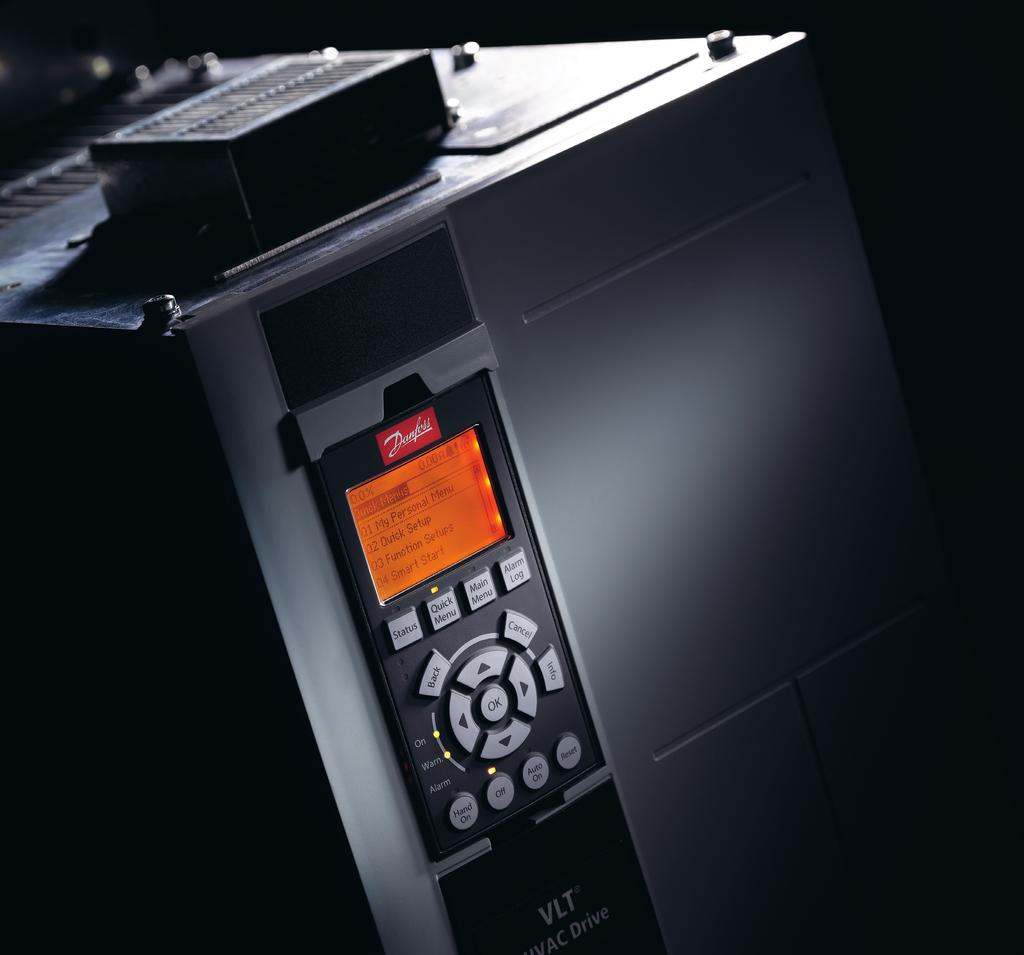
11 Product Overview Installation Guide 3.3 Control Shelf The control shelf contains the LCP, MDCIC, and control card. The LCP provides access to the system parameters. The MDCIC is connected to each of the drive modules via a ribbon cable and communicates to the control card. The control card controls the operation of the drive modules BE597. LCP cradle 7 MDCIC card Control card (underneath cover) 8 Control shelf 3 Control terminal blocks 9 Switch mode power supply (SMPS). Note that an external 30 V supply is needed to power the SMPS. 4 Top-level drive system label. See Illustration Pilz relay 5 44-pin cables from MDCIC board to drive modules DIN rail 6 Ferrite core Terminal block mounted on DIN rail Illustration 3. Control Shelf MG37K30 Danfoss A/S 08/07 All rights reserved. 9
12 Product Overview VLT Parallel Drive Modules 3.4 Wire Harness 3 The VLT Parallel Drive Modules basic kit contains the following wire harnesses: Ribbon cable with 44-pin connector (on both ends of the cable) Relay cable with 6-pin connector (on end of the cable) DC fuse microswitch cable with -pin connectors (on end of the cable) 3.5 DC Fuses The VLT Parallel Drive Modules kit contains DC fuses per drive module. These fuses on the supply side ensure that any damage is contained to inside the drive modules. NOTICE Use of fuses on the supply side is mandatory for IEC (CE) compliant installations. 30BE750.0 DC fuse Microswitch connector Illustration 3.3 DC Fuse and Microswitch Connector 0 Danfoss A/S 08/07 All rights reserved. MG37K30
13 Mechanical Installation Installation Guide 4 Mechanical Installation 4. Receiving and Unpacking the Unit 4.. Items Supplied VLT R AutomationDrive T/C: FC-BDMN50T5E00HSXC7XXSXXXXAXBXCXXXXDX P/N: 78N005 S/N: 3456H3 30BE7.4 Make sure that the items supplied and the information on the labels correspond to the order. - Top-level drive system. This label is found on the control shelf, lower right side of the LCP. See Illustration Drive module. This label is found inside the drive module enclosure, on the right side panel. See Illustration 3.. Visually check the packaging and the VLT Parallel Drive Modules components for damage caused by inappropriate handling during shipment. File any claim for damage with the carrier. Retain damaged parts, in case clarification is needed. 3 4 Intended use - The Individual Base Drive Modules are intended for use in Parallel Drive Module system only. Specific electrical ratings are not applicable. Name plate of Parallel Drive Module system should be referred for actual drive ratings. CHASSIS (OPEN TYPE) / IP00 SCCR 00 ka at UL Voltage range V ASSEMBLED IN USA Listed 36U0 E7054 IND. CONT. EQ. UL Voltage range V CAUTION - ATTENTION: See manual for special condition / prefuses Voir manuel de conditions speciales / fusibles WARNING - AVERTISSEMENT: Stored charge, wait 0 min. Charge residuelle, attendez 0 ` ` VLT R AutomationDrive T/C: FC-30N70T5E00PBGC7XXSXXXXAXBXCXXXXDX P/N: 34X409 S/N: 3456H3 70 kw / 000 HP, High Overload IN: 3x V 50/60Hz 7/9 A OUT: 3x0-Vin 0-590Hz 60/60 A 30BE70. Type code Code number 3 Intended use disclaimer 4 Discharge time 5 Serial number 800 kw / 00 HP, Normal Overload IN: 3x V 50/60Hz 4/344 A OUT: 3x0-Vin 0-590Hz 460/380 A Illustration 4. Drive Module Label (Example) CHASSIS (OPEN TYPE) / IP00 Tamb. 45 C/3 F at Full Output Current Max. Tamb. 55 C/3 F w/ Output Current Derating SCCR 00 ka at UL Voltage range V ASSEMBLED IN USA Listed 36U0 E7054 IND. CONT. EQ. UL Voltage range V NOTICE LOSS OF WARRANTY Removing the labels from the VLT Parallel Drive Modules can result in loss of warranty. 6 CAUTION - ATTENTION: See manual for special condition / prefuses Voir manuel de conditions speciales / fusibles WARNING - AVERTISSEMENT: Stored charge, wait 0 min. Charge residuelle, attendez 0 ` ` Type code Code number 3 Power rating 4 Input voltage, frequency, and current 5 Output voltage, frequency, and current 6 Discharge time Illustration 4. Top-level Drive System Label (Example) MG37K30 Danfoss A/S 08/07 All rights reserved.
14 Mechanical Installation VLT Parallel Drive Modules Receiving and unloading I-beam and hooks rated to lift a drive module having a weight of 5 kg (75 lb), with the necessary safety margins. Crane or other lifting aid rated to lift the minimum weight specified in the documentation package supplied with the drive module. Crowbar to disassemble the wooden shipping container. 4 Installation Drill with 0 mm or mm drill bits. Tape measurer. Screwdriver. Wrench with relevant metric sockets (7 7 mm). Wrench extensions. Torx T50 tool. Cabinet construction Acquire the tools necessary for assembly of the panel - according to the design plans and established practices. 4.. Lifting the Unit For measurements and center of gravity, see chapter 7.8 Kit Dimensions. Ensure that the lifting device is suitable for the task. Move the unit using a hoist, crane, or forklift with the appropriate rating. Always use the dedicated lifting eye bolts. See Illustration 4.3. CAUTION HEAVY LOAD Unbalanced loads can fall and loads can tip over. Failure to take proper lifting precautions increases risk of death, serious injury, or equipment damage. Never walk under suspended loads. To guard against injury, wear personal protective equipment such as gloves, safety glasses, and safety shoes. Be sure to use lifting devices with the appropriate weight rating. The lifting bar must be able to handle the weight of the load. The load s center of gravity may be in an unexpected location. Failure to locate the center of gravity correctly and position the load accordingly before lifting the load can cause the unit to fall over or tilt unexpectedly during lifting and transport. The angle from the top of the drive module to the lifting cables has an impact on the maximum load force on the cable. This angle must be 65 or greater. Refer to Illustration 4.3. Attach and dimension the lifting cables properly Storage Store the kit in a dry location. Keep the equipment sealed in its packaging until installation. Refer to chapter 7.5 Ambient Conditions for Drive Modules for recommended ambient conditions. Danfoss A/S 08/07 All rights reserved. MG37K30
15 Mechanical Installation Installation Guide 30BE min 4 4 Illustration 4.3 Lifting the Drive Module MG37K30 Danfoss A/S 08/07 All rights reserved. 3
16 Mechanical Installation VLT Parallel Drive Modules 4. Requirements 4..3 Busbars 4 This section describes the minimum recommended requirements for mechanical installation. For UL and CE requirements, see chapter 5. Electrical Requirements for Certifications and Approvals. 4.. Environmental Refer to for information on required operating temperature, humidity, and other environmental conditions. 4.. Cabinet The kit consists of either or 4 drive modules, depending on the power rating. The cabinets have to meet the following minimum requirements: Width [mm (in)] -drive: 800 (3.5), 4-drive: 600 (63) Depth [mm (in)] 600 (3.6) Height [mm (in)] 000 (78.7) ) Weight capacity [kg (lb)] Ventilation openings -drive: 450 (99), 4-drive: 90 (006) See chapter 4..5 Cooling and Airflow Requirements. Table 4. Cabinet Requirements ) Required if Danfoss busbar or cooling kits are used. NOTICE EXTERNAL 30 V SUPPLY An external 30 V supply is required for the SMPS (switch mode power supply). Danfoss recommends using a 6 A, 0 A, or 6 A slow-blow fuse when installing the external supply. If the Danfoss busbar kit is not used, see Table 4. for the cross-section measurements that are required when creating customized busbars. For terminal dimensions, refer to chapter 7.8. Terminal Dimensions and chapter DC Bus Dimensions. Description Width [mm (in)] Thickness [mm (in)] AC motor 43.6 (5.7) 6.4 (0.5) AC mains 43.6 (5.7) 6.4 (0.5) DC bus 76. (3.0).7 (0.50) Table 4. Cross-section Measurements for Customized Busbars NOTICE Align busbars vertically to provide maximum airflow Thermal Considerations For heat dissipation values, refer to chapter 7. Powerdependent Specifications. The following heat sources must be considered when determining cooling requirements: Ambient temperature outside enclosure. Filters (for example, sine-wave and RF). Fuses. Control components. For required cooling air, refer to chapter 4..5 Cooling and Airflow Requirements. 4 Danfoss A/S 08/07 All rights reserved. MG37K30
17 Mechanical Installation Installation Guide 4..5 Cooling and Airflow Requirements The recommendations provided in this section are necessary for effective cooling of the drive modules within the panel enclosure. Each drive module contains a heat sink fan and a mixing fan. Typical enclosure designs utilize door fans along with the drive module fans to remove waste heat from the enclosure. Danfoss provides several back-channel cooling kits as options. These kits remove 85% of the waste heat from the enclosure, reducing the need for large door fans. NOTICE Make sure that the total flow of the cabinet fans meets the recommended airflow. 4 4 Drive module cooling fans The drive module is equipped with a heat sink fan, which provides the required flow rate of 840 m 3 /h (500 cfm) across the heat sink. Also, there is a cooling fan mounted on the top of the unit, and a small 4 V DC mixing fan mounted under the input plate that operates any time the drive module is powered on. In each drive module, the power card provides DC voltage to power the fans. The mixing fan is powered by 4 V DC from the main switch mode power supply. The heat sink fan and the top fan are powered by 48 V DC from a dedicated switch mode power supply on the power card. Each fan has a tachometer feedback to the control card to confirm that the fan is operating correctly. On/off and speed control of the fans help reduce unnecessary acoustical noise and extend the life of the fans. Cabinet fans When the back-channel option is not used, fans mounted in the cabinet must remove all the heat generated inside the enclosure. For each enclosure housing drive module, the cabinet fan flow recommendation is as follows: When back-channel cooling is used, 680 m 3 /h (400 cfm) flow is recommended. When back-channel cooling is not used, 4080 m 3 /h (400 cfm) flow is recommended. 30BE569.0 Illustration 4.4 Airflow, Standard Unit (Left), Bottom/Top Cooling Kit (Middle), and Back/Back Cooling Kit (Right) MG37K30 Danfoss A/S 08/07 All rights reserved. 5
18 Mechanical Installation VLT Parallel Drive Modules 4.3 Installing the Drive Modules Install the drive modules into the cabinet frame as described in the following steps. 4. Unpack the drive modules from the packaging. See chapter 4. Receiving and Unpacking the Unit.. Install eye bolts in the top of the first drive module. Prepare the drive module for lifting, using an appropriate lifting harness and an overhead hoist or crane with the necessary lifting capacity. See chapter 4.. Lifting the Unit. 30BE57.0 Illustration 4.5 Installation of Eye Bolts 3. Install the bottom mounting screws and gaskets onto the mounting panel. 4. Using the crane or hoist, lift the drive module and then lower the unit through the top of the cabinet frame. Align the bottom mounting holes of the unit with the bottom mounting screws on the mounting panel. 5. Verify that the drive module is correctly aligned on the mounting panel and then secure the bottom of the unit to the panel with the hex nuts. See Illustration 4.6. Torque the hex nuts. Refer to chapter 7.9 Fastener Tightening Torques. 6. Secure the top of the unit to the mounting panel with M0x6 screws, and then torque the screws. 7. Line up the groove on the microswitch with the edges on each DC fuse and press firmly until the microswitch clicks into place. 8. Install DC fuses with microswitches onto the tops of the DC-link terminals on each drive module. The microswitches should be installed on the outer side of each terminal. Refer to Illustration Secure each fuse with M0 screws and torque the screws. 0. Install the next drive module. 6 Danfoss A/S 08/07 All rights reserved. MG37K30
19 Installation Guide 30BE57.0 Mechanical Installation 4 4 Illustration 4.6 Installation of Bottom Mounting Bolts MG37K30 Danfoss A/S 08/07 All rights reserved. 7
20 VLT Parallel Drive Modules Mechanical Installation 4.4 Installing the Control Shelf NOTICE To avoid RFI, do not route control wiring together with power cables or bus bars. Remove the control shelf assembly from its package.. Remove the LCP from the control shelf. 3. Use some type of mounting bracket to install the control shelf. Danfoss does not supply the mounting brackets for the control shelf. For EMC-correct installation, refer to Illustration Remove the MDCIC cover from the control shelf assembly. 5. Connect the 44-pin ribbon cables from the MDCIC card to the top of the drive modules, following the sequence numbers indicated next to the connectors on the MDCIC. 6. Route the 44-pin ribbon cables inside the cabinet. 7. Connect the external brake fault wiring harness between the microswitch terminals and the brake jumper connector on the top of the drive module. 8. Connect the relay wiring between relay or on the control shelf and the corresponding relay connector on the top of the drive module. 9. Connect the microswitch to the microswitch connector provided on the top of the drive module. Refer to Illustration 3. and Illustration BE Control shelf must stay below this point Control shelf must stay above this point Illustration 4.7 Positioning the Control Shelf for EMC-correct Installation 8 Danfoss A/S 08/07 All rights reserved. MG37K30
21 Electrical Installation Installation Guide 5 Electrical Installation 5. Safety Instructions See chapter Safety for general safety instructions. WARNING INDUCED VOLTAGE When output motor cables from different frequency converters are run together, induced voltage can charge equipment capacitors even with the equipment turned off and locked out. To avoid death or serious injury: Run output motor cables separately or use shielded cables. Simultaneously lock out all the frequency converters. CAUTION SHOCK HAZARD The drive system can cause a DC current in the protective earth (PE) conductor. When a residual current-operated protective device (RCD) is used for protection against electrical shock, only an RCD of Type B is allowed on the supply side. Failure to follow this recommendation could prevent the RCD from providing the intended protection. NOTICE MOTOR OVERLOAD PROTECTION The drive modules are supplied with Class 0 overload protection for single motor applications. Overcurrent protection Extra protective equipment, such as short-circuit protection or motor thermal protection between the drive modules and the motors, is required for applications with multiple motors. The correct input fusing is required to acquire approvals and meet certification requirements, and to provide short circuit and overcurrent protection. These fuses are not factory-supplied, and must be provided by the installer. See maximum fuse ratings in chapter 7. Powerdependent Specifications. Wire type and ratings All wiring must comply with local and national regulations regarding cross-section and ambient temperature requirements. Power connection wire recommendation: minimum 75 C rated copper wire. See chapter 7.6 Cable Specifications for recommended wire sizes and types. CAUTION PROPERTY DAMAGE Electronic thermal relay (ETR) protection against motor overload is not included in the default setting. To program the LCP for this function, refer to the VLT Parallel Drive Modules User Guide. 5 5 MG37K30 Danfoss A/S 08/07 All rights reserved. 9
22 Electrical Installation VLT Parallel Drive Modules 5. Electrical Requirements for Certifications and Approvals 5 The standard configuration provided in this guide (drive modules, control shelf, wire harnesses, fuses, and microswitches) is UL and CE certified. The following conditions must be met apart from the standard configuration to obtain UL and CE regulatory approval requirements. For a list of disclaimers, see chapter 8. Disclaimer. Use the frequency converter in a heated, indoorcontrolled environment. Cooling air must be clean, free from corrosive materials, and electrically conductive dust. See for specific limits. Maximum ambient air temperature is 40 C (04 F) at rated current. The drive system must be assembled in clean air, according to enclosure classification. To obtain UL or CE certification regulatory approvals, drive modules must be installed according to the standard configuration provided in this guide. Maximum voltage and current must not exceed the values provided in chapter 7. Powerdependent Specifications for the specified drive configuration. The drive modules are suitable for use on a circuit capable of delivering not more than 00 ka rms symmetrical amperes at the drive nominal voltage (600 V maximum for 690 V units) when protected by fuses with the standard configuration. Refer to chapter 5.4. Fuse Selection. The ampere rating is based on tests done according to UL 508C. The cables located within the motor circuit must be rated for at least 75 C (67 F) in ULcompliant installations. The cable sizes have been provided in chapter 7. Power-dependent Specifications for the specified drive configuration. The input cable must be protected with fuses. Circuit breakers must not be used without fuses in the U.S. Suitable IEC (class ar) fuses and UL (class L or T) fuses are listed in chapter 5.4. Fuse Selection. In addition, country-specific regulatory requirements must be adhered to. For installation in the U.S., branch circuit protection must be provided according to the National Electrical Code (NEC) and any applicable local codes. To fulfill this requirement, use ULclassified fuses. For installation in Canada, branch circuit protection must be provided according to the Canadian Electrical Code and any applicable provincial codes. To fulfill this requirement, use the UL-classified fuses. 0 Danfoss A/S 08/07 All rights reserved. MG37K30
23 Electrical Installation Installation Guide 5.3 Wiring Diagram 30 V AC 50/60 Hz L N 30 V/4 V Power supply 30BE phase power input Regen terminals +0 V DC 0 V DC - 0 V DC 0/4-0 ma 0 V DC - 0 V DC 0/4-0 ma 9 (L) 9 (L) 93 (L3) 95 PE 88 (-) 89 (+) 50 (+0 V OUT) A53 U-I (S0) 53 (A IN) A54 U-I (S0) 54 (A IN) 55 (COM A IN) (+4 V OUT) 3 (+4 V OUT) 8 (D IN) 9 (D IN) 0 (COM D IN) 7 (D IN/OUT) 9 (D IN/OUT) 3 (D IN) 33 (D IN) 37 (D IN) - option ON ON ON=0 0 ma OFF=0 0 V 4 V 0 V 4 V 0 V P 5-00 Switch mode Power supply 0 V DC 4 V DC 5 ma 00 ma V (NPN) 0 V (PNP) 4 V (NPN) 0 V (PNP) 4 V (NPN) 0 V (PNP) 4 V (NPN) 0 V (PNP) 4 V (NPN) 0 V (PNP) 4 V (NPN) 0 V (PNP) S80/Bus Term. OFF-ON 5 V ON (U) 96 (V) 97 (W) 98 (PE) 99 (R+) 8 (R-) 8 Relay Relay (COM A OUT) 39 (A OUT) 4 ON=Terminated OFF=Open 0 V S80 RS485 (P RS485) 68 Interface (N RS485) 69 (COM RS485) 6 Brake resistor 40 V AC, A 400 V AC, A 40 V AC, A 400 V AC, A Analog output 0/4 0 ma Brake Temp (NC) RS485 (PNP) = Source (NPN) = Sink Motor 5 5 Illustration 5. Wiring Diagram MG37K30 Danfoss A/S 08/07 All rights reserved.
24 Electrical Installation VLT Parallel Drive Modules Fuses 5.4. Fuse Selection To protect the drive system in case or more internal components break down within a drive module, use fuses and/or circuit breakers at the mains supply side Branch Circuit Protection To protect the installation against electrical and fire hazards, protect all branch circuits in an installation against short circuit and overcurrent according to national and international regulations Short-circuit Protection Danfoss recommends the fuses listed in chapter Recommended Fuses for CE Compliance and chapter Recommended Fuses for UL Compliance to achieve CE or UL Compliance in the protection of service personnel and property against the consequences of component breakdown in the drive modules Recommended Fuses for CE Compliance Number of drive modules FC 30 FC 0/ FC 0 Recommended fuse (maximum) N450 N500 ar N500 N560 ar N560 N630 ar N630 N70 ar N70 N800 ar N800 NM0 ar-500 Table 5. 6-Pulse Drive Systems ( V AC) Number of drive modules FC 30 FC 0/ FC 0 Recommended fuse (maximum) N50 N35 ar-630 N35 N355 ar-630 N355 N400 ar-630 N400 N450 ar-800 N450 N500 ar N500 N560 ar N560 N630 ar N630 N70 ar N70 N800 ar N800 NM0 ar-600 Table 5. -Pulse Drive Systems ( V AC) Number of drive modules FC 30 FC 0/ FC 0 Recommended fuse (maximum) 4 N630 N70 ar N70 N800 ar N800 N900 ar N900 NM0 ar NM0 NM ar-500 Table Pulse Drive Systems ( V AC) Number of drive modules FC 30 FC 0/ FC 0 Recommended fuse (maximum) N50 N35 ar-550 N35 N355 ar-630 N355 N400 ar-630 N400 N500 ar-630 N500 N560 ar-630 N560 N630 ar N630 N70 ar N70 N800 ar N800 N900 ar N900 NM0 ar NM0 NM ar-600 Table 5.4 -Pulse Drive Systems ( V AC) Recommended Fuses for UL Compliance The drive modules are supplied with built-in AC fuses. The modules have been qualified for 00 ka short-circuit current rating (SCCR) for the standard busbar configurations at all voltages ( V AC). If no power options or extra busbars are connected externally, the drive system is qualified for 00 ka SCCR with any Class L or Class T ULlisted fuses connected at the input terminals of the drive modules. Do not exceed the listed fuse rating in Table 5.6 to Table 5.7 with the current rating of the Class L or Class T fuses. Number of drive modules FC 30 FC 0/ FC 0 Recommended fuse (maximum) N450 N A 4 N500 N A 4 N560 N A 4 N630 N A 4 N70 N A 4 N800 NM0 500 A Table Pulse Drive Systems ( V AC) Danfoss A/S 08/07 All rights reserved. MG37K30
25 Electrical Installation Installation Guide Number of drive modules FC 30 FC 0/ FC 0 Recommended fuse (maximum) N50 N A N35 N A N355 N A N400 N A N450 N A 4 N500 N A 4 N560 N A 4 N630 N A 4 N70 N A 4 N800 NM0 600 A Table 5.6 -Pulse Drive Systems ( V AC) 5 5 Any minimum 500 V UL-listed fuse can be used for the V AC drive systems. Number of drive modules FC 30 FC 0/ FC 0 Recommended fuse (maximum) 4 N630 N A 4 N70 N A 4 N800 N A 4 N900 NM0 500 A 4 NM0 NM 500 A Table Pulse Drive Systems ( V AC) Number of drive modules FC 30 FC 0/ FC 0 Recommended fuse (maximum) N50 N A N35 N A N355 N A N400 N A N500 N A N560 N A 4 N630 N A 4 N70 N A 4 N800 N A 4 N900 NM0 600 A 4 NM0 NM 600 A Table 5.8 -Pulse Drive Systems ( V AC) Any minimum 700 V UL-listed fuse can be used for the V AC drive systems. MG37K30 Danfoss A/S 08/07 All rights reserved. 3
26 Electrical Installation VLT Parallel Drive Modules Electrical Kit Installation This section describes how the electrical kit is used to connect or 4 drive modules in parallel - to provide controlled power to an AC motor. A diagram is provided for each of the 4 configurations which, if followed, meet specific agency approvals and certifications. If designing and building other configurations, seek agency approvals or certifications apart from Danfoss. Read this section for guidance in making electrical connections when assembling the drive modules into a panel. 5.6 DC Bus Fuse Installation DC fuses are provided in the basic kit. Install the DC fuses at the available DC terminals at individual drive modules, using the recommended bolts. Each DC fuse has a fixture for mounting the microswitches, which are used to detect a fuse failure. See Illustration 3.3. Install the supplied harness between the microswitch terminals and the brake fault jumper port on the top of the drive modules. If the jumper is not installed properly, the unit does not power up and the error Brake IGBT Fault is shown. The microswitch has 3 terminals: NO, NC, and COM. Connect the wire harness between the NC and COM terminals. If it is connected between any other terminals, the unit does not power up, and the error Brake IGBT Fault is shown. NOTICE The microswitch is a snap fit onto the fuse. Ensure that the switch is properly installed on the fuses. 5.7 Motor Connections 5.7. Motor Cables See chapter 7.6 Cable Specifications for more information on wire type and sizes. NOTICE SHIELDED CABLE LENGTH With a standard VLT Parallel Drive Modules drive system, shielded cables up to 50 m (49 ft) long or unshielded up to 300 m (984 ft) long provide full voltage at the motor. If this cable length is exceeded, use a du/dt filter. For information on the selection of a du/dt filter, refer to the VLT Parallel Drive Modules Design Guide Voltage Rating Peak voltages up to.8 times the mains voltage of the VLT Parallel Drive Modules drive system can occur in the motor cable. High peak voltages can severely stress the motor cable. Use motor cables with rated voltage specification of at least 0.6/ kv. Cables in this range provide good resistance to insulation breakdown Dimensions Follow local codes for current capacity data for cables and conductors. Widely used codes include: NFPA 70, EN 6004-, VDE 03-, and VDE Overdimensioning for harmonics is not required Length Keep cables as short as possible. Voltage drop and heat dissipation depends on the frequency and is approximately proportional to cable length. Consult the cable manufacturer specifications regarding the length and expected voltage drop when connected to the drive system. See chapter 7.6 Cable Specifications Shielding The following factors are important for effective shielding: Make sure that the amount of cable surface covered by the shield is at least 80%. Use a single-layer braided copper shield. Ensure that the shield is braided to reduce surface area for leakage currents. Use cables with double shielding to improve the attenuation of interference further. Twisted conductors reduce magnetic fields. Use cables that are shielded at both ends between the drive system and the motor. To comply with radio frequency interference limits, shield the cables between the drive system and the motor at both ends. Ensure that the shield fully surrounds the cable. Route cable glands or cable clamps directly to the grounding point. Keep connections as short as possible at each end of the cable. Bridge shield gaps such as terminals, switches, or contactors by using connections with the lowest possible impedance and the largest possible surface area. NOTICE TWISTED SHIELD ENDS (PIGTAILS) Twisted shield ends increase the shield impedance at higher frequencies, which reduces the shield effect and increases the leakage current. To avoid twisted shield ends, use integrated shield clamps. Refer to Illustration Danfoss A/S 08/07 All rights reserved. MG37K30
27 Electrical Installation Installation Guide Using a digital input and 4 V as supply PE PE 30BE V A B GND OFF 30BA5. PE PE Correct grounding of shielded ends Incorrect grounding using twisted shield ends (pigtail) Illustration 5. Example of Shield Ends PTC / Thermistor ON <6.6 k Ω >0.8 k Ω Illustration 5.5 PTC Thermistor Connection - Digital Input with 4 V Supply Check that the selected supply voltage follows the specification of the used thermistor element. R Types of Thermal Protection PTC Thermistor Input digital/ analog Supply voltage [V] Trip resistance kω Reset resistance Digital 0 >.7 <800 Ω Analog 0 >3.0 <3.0 kω Digital 4 >0.8 <6.6 kω Using a digital input and 0 V supply +0V BA5.0 Table 5.9 PTC Thermistor Resistance Parameters OFF ON PTC / Thermistor <800 Ω >.7 kω R Illustration 5.3 PTC Thermistor Connection - Digital Input with 0 V Supply Using an analog input and 0 V supply +0V OFF 30BA53. PTC / Thermistor ON <3.0 k Ω >3.0 k Ω R Illustration 5.4 PTC Thermistor Connection - Analog Input with 0 V Supply MG37K30 Danfoss A/S 08/07 All rights reserved. 5
28 Electrical Installation VLT Parallel Drive Modules KTY Sensor The frequency converter handles 3 types of KTY sensors: KTY Sensor : kω at 00 C ( F). Philips KTY 84- is an example. KTY Sensor : kω at 5 C (77 F). Philips KTY 83- is an example. KTY Sensor 3: kω at 5 C (77 F). Philips KTY-0 is an example. Resistance [Ohm] BB97.0 NOTICE Danfoss is not responsible for the failure of any Klixon thermal switch Motor Terminal Connections WARNING INDUCED VOLTAGE Induced voltage from output motor cables from different frequency converters that are run together can charge equipment capacitors even with the equipment turned off and locked out. Failure to run output motor cables separately or use shielded cables could result in death or serious injury. Run output motor cables separately. Or Use shielded cables. Simultaneously lock out all the frequency converters Temperature [ C] Illustration 5.6 KTY Type Selection KTY type KTY type KTY type 3 NOTICE PELV COMPLIANCE If short circuits occur between motor windings and the sensor, PELV compliance is not achieved when the motor temperature is monitored via a thermistor or KTY sensor. Ensure that the sensor is isolated better Brake Resistor Thermal Switch Installation Each drive module has a brake fault jumper connector on the top plate, which is used to connect the Klixon thermal switch on the brake resistors. This connector has a preinstalled jumper as shown in Illustration 8.3. The brake fault jumper must always be in place to ensure proper operation of the drive module. Without this jumper connection, the drive module does not allow the inverter to operate, and a brake IGBT fault is shown. The thermal switch is a normally-closed type. If the brake resistor temperature exceeds recommended values, the thermal switch opens. Use mm (8 AWG), reinforced and doubly insulated wire for the connection. See Illustration 8.5. Comply with local and national electrical codes for cable sizes. For maximum cable sizes, see chapter 7. Power-dependent Specifications. Follow motor manufacturer wiring requirements. Do not wire a starting or pole-changing device (for example, Dahlander motor or slip ring induction motor) between the drive system and the motor Motor Cable All types of 3-phase asynchronous standard motors can be used with the drive system. Connect the motor to the following terminals: U/T/96 V/T/97 W/T3/98 Ground to terminal 99 Factory setting is for clockwise rotation with the drive system output connected as follows: Terminal number Function 96 Mains U/T 97 V/T 98 W/T3 99 Ground Table 5.0 Motor Cable Terminals 6 Danfoss A/S 08/07 All rights reserved. MG37K30
29 Electrical Installation Installation Guide Changing motor rotation Terminal U/T/96 connected to U-phase Terminal V/T/97 connected to V-phase Terminal W/T3/98 connected to W-phase Motor U V W FC U V W 75HA Motor Terminal Connections in - Drive Module Systems Illustration 8.9 and Illustration 8.0 show the bus bar connections for 6-pulse and -pulse -drive systems, respectively. If a common terminal design is used, there is set of motor terminals. NOTICE MULTIPLE MOTOR CABLES If connecting more than set of motor terminals, use the same number, size, and length of cables for each set of terminals. For example, do not use cable on one motor terminal and cables on another motor terminal Measure between the common terminals and the first common point of a phase, typically the motor terminals. Motor U V W. Strip a section of the outer cable insulation. 3. Connect the ground wire to the nearest protective earth terminal. U V W 4. Connect the 3-phase motor wiring to terminals U/96, V/97, and W/98 using M0 screws. 5. Tighten the motor terminals. See chapter 7.9. Tightening Torques for Terminals. FC Motor Terminal Connections in 4- Drive Module Systems Illustration 5.7 Changing Motor Rotation The direction of rotation can be changed by switching phases in the motor cable, or by changing the setting of parameter 4-0 Motor Speed Direction. Motor rotation check can be performed using parameter -8 Motor Rotation Check and following the steps shown in Illustration 5.7. Illustration 8. shows the bus bar connections for a 4-drive system. If a common terminal design is used, there is set of motor terminals in each cabinet. NOTICE MULTIPLE MOTOR CABLES If connecting more than set of motor terminals, use the same number, size, and length of cables for each set of terminals. For example, do not use cable on one motor terminal and cables on another motor terminal.. Measure between the common terminals and the first common point of a phase, typically the motor terminals.. Strip a section of the outer cable insulation. 3. Connect the ground wire to the nearest protective earth (ground) terminal. 4. Connect the 3-phase motor wiring to terminals U/96, V/97, and W/98 using M0 screws. 5. Tighten the motor terminals. See chapter 7.9. Tightening Torques for Terminals. MG37K30 Danfoss A/S 08/07 All rights reserved. 7
30 Electrical Installation VLT Parallel Drive Modules Mains Connections There are several types of AC mains systems for supplying power to frequency converters. Each affects the EMC characteristics of the system. The 5-wire TN-S systems are regarded as best regarding EMC, while the isolated IT system is the least preferred. System type TN mains systems TN-S TN-C TT mains systems IT grid system Description There are types of TN mains distribution systems: TN-S and TN-C. A 5-wire system with separate neutral (N) and protective earth (PE) conductors. It provides the best EMC properties and avoids transmitting interference. A 4-wire system with a common neutral and protective earth (PE) conductor throughout the system. The combined neutral and PE conductor results in poor EMC characteristics. A 4-wire system with a grounded neutral conductor and individual grounding of the drive system. It has good EMC characteristics when grounded properly. An isolated 4-wire system with the neutral conductor either not grounded or grounded via an impedance. Table 5. AC Mains Systems and EMC Characteristics 5.8. AC Mains Terminal Connections When making mains connections, observe the following: Size the wiring based on the input current of the frequency converter. For maximum wire sizes, see chapter 7. Power-dependent Specifications. Comply with local and national electrical codes for cable sizes Mains Terminal Connections in - Drive Module Systems Illustration 8.9 and Illustration 8.0 show the bus bar connections for 6-pulse and -pulse -drive systems, respectively. If a common terminal design is used with a 6- pulse, -drive system, there is set of mains terminals. Common terminal design cannot be used with -pulse mains connections in a -drive module systems. The mains cables are connected directly to the drive input terminals. There are individual brake terminals available in each drive module. Connect an equal number of recommended cables to the individual brake terminals. NOTICE MULTIPLE MAINS CABLES If connecting more than set of mains terminals, use the same number, size, and length of cables for each set of terminals. For example, do not use cable on one mains terminal and cables on another mains terminal.. Measure between the common terminals and the first common point of a phase, typically the mains terminals.. For -pulse drive modules, the set of cables from the st drive module connects to the starsecondary winding of the -pulse transformer. The set from the nd drive module connects to the delta-secondary winding of the -pulse transformer. 3. Strip a section of the outer cable insulation. 4. Connect the ground wire to the nearest ground terminal. 5. Connect the 3-phase mains wiring to terminals R/9, S/9, and T/93 using M0 screws. 6. Tighten the mains terminals. See chapter 7.9. Tightening Torques for Terminals. 8 Danfoss A/S 08/07 All rights reserved. MG37K30
MAKING MODERN LIVING POSSIBLE. Quick Setup VLT FCM 300 Series. Phone: Fax: Web: -
 MAKING MODERN LIVING POSSIBLE Quick Setup VLT FCM 300 Series Factory setting Motors type B14 & B34 mounting Reset (pushbutton) Start Jog Speed reference Fig. 1 - Reset to be closed short time for resetting
Operating Guide VLT AQUA Drive FC 202
 ENGINEERING TOMORROW Operating Guide VLT AQUA Drive FC 202 0.25 90 kw vlt-drives.danfoss.com Contents Operating Guide Contents 1 Introduction 4 1.1 Purpose of the Operating Guide 4 1.2 Additional Resources
FLÄKTGROUP PM-MOTOR WITH INTEGRATED FC 106 FREQUENCY CONVERTER
 FLÄKTGROUP PM-MOTOR WITH INTEGRATED FC 106 FREQUENCY CONVERTER INSTALLATION AND MAINTENANCE INSTRUCTIONS Risk of electric shock: Motor terminals may still be live if the impeller is rotating, even when
MAKING MODERN LIVING POSSIBLE. Instruction Manual. VLT AutomationDrive FC 300, kw
 MAKING MODERN LIVING POSSIBLE Instruction VLT AutomationDrive FC 300, 0.25 75 kw Safety Safety WARNING HIGH VOLTAGE! Adjustable frequency drives contain high voltage when connected to AC line power. Installation,
5. Installation on Pedestal - IP 21 / IP 54 Units 43
 Contents Contents 1. General Information 3 2. Preinstallation 7 Planning the Installation Site 7 Receiving the Frequency Converter 7 Transportation and Unpacking 7 Lifting 8 Shipping Weights and Dimensions
Observe all necessary safety precautions when controlling the soft starter remotely. Alert personnel that machinery may start without warning.
 Introduction OPERATING INSTRUCTIONS: MCD REMOTE OPERATOR Order Codes: 175G94 (for MCD 2) 175G361 + 175G9 (for MCD 5) 175G361 (for MCD 3) 1. Introduction 1.1. Important User Information Observe all necessary
VLT AutomationDrive FC Pulse Instruction Manual VLT AutomationDrive FC 300
 MAKING MODERN LIVING POSSIBLE VLT AutomationDrive FC 300 12-Pulse Instruction Manual VLT AutomationDrive FC 300 Contents Contents 1 How to Read the Instruction Manual 1-1 1.1.2 Abbreviations 1-2 2 Safety
REFERENCE MANUAL FORM: MX-TRM-E REL REV MTE
 Matrix APAX 380V-415V 50Hz TECHNICAL REFERENCE MANUAL FORM: MX-TRM-E REL. September 2014 REV. 002 2014 MTE Corporation WARNING High Voltage! Only a qualified electrician can carry out the electrical installation
Matrix APAX. 380V-415V 50Hz TECHNICAL REFERENCE MANUAL
 Matrix APAX 380V-415V 50Hz TECHNICAL REFERENCE MANUAL WARNING High Voltage! Only a qualified electrician can carry out the electrical installation of this filter. Quick Reference ❶ Performance Data Pages
Installation Instructions Bus Bar Kit for 6-pulse, 4-drive System VLT Series FC 102, FC 202, and FC 302. Description. Kit Part Number.
 Description The bus bar kit is designed for the specific VLT HVAC Drive FC 102, VLT AQUA Drive FC 202, and VLT AutomationDrive FC 302 D4h-size VLT Parallel Drive Modules mounted in a Rittal TS8 enclosure.
www. ElectricalPartManuals. com Instruction Bulletin ALTIVAR FLEX58 TRX Adjustable Speed Chassis Drive Controllers Installation Guide
 Instruction Bulletin ALTIVAR FLEX58 TRX Adjustable Speed Chassis Drive Controllers Installation Guide Retain for future use. 30072-450-47A July 2002 Raleigh, NC, USA HAZARDOUS VOLTAGE Read and understand
MAKING MODERN LIVING POSSIBLE. Instruction Manual VLT AutomationDrive FC 300
 MAKING MODERN LIVING POSSIBLE Instruction VLT AutomationDrive FC 300 Safety Safety WARNING HIGH VOLTAGE! Adjustable frequency drives contain high voltage when connected to AC line power. Installation,
Brake Resistor Design Guide. How to Read this Design Guide 3 Abbreviations 4. Safety Precautions 5 CE Conformity and Labelling 5
 Brake Resistor Design Guide Contents Contents 1 How to Read this Design Guide 3 How to Read this Design Guide 3 Abbreviations 4 2 Safety and Conformity 5 Safety Precautions 5 CE Conformity and Labelling
Installation Instructions 300 A Current Sensor Kit for D1h/D3h/D5h/D6h Enclosure Sizes VLT Series FC 102, FC 103, FC 202, and FC 302
 1.1 Description The 300 A current sensor kit is designed for D1h/D3h/D5h/D6h enclosure sizes in the power ranges shown in Table 1.1. To identify the power rating, see Illustration 1.1. Product group and
USERS MANUAL MCD REMOTE OPERATOR
 USERS MANUAL MCD REMOTE OPERATOR Order Code: 175G9004, 175G3061 Contents Contents Introduction...2 Important User Information...2 General Description...2 Symbols Used in this Manual...2 Installation...3
High Frequency SineWave Guardian TM
 High Frequency SineWave Guardian TM 380V 480V INSTALLATION GUIDE FORM: SHF-IG-E REL. January 2018 REV. 002 2018 MTE Corporation High Voltage! Only a qualified electrician can carry out the electrical installation
Appendix: Safety and application notes for... 15
 Contents Safety... 2 Warnings... 2 Symbols used in this manual... 2 Operator s safety... 2 Avoid filter module damage... 2 DC-link resonance... 2 Description... 3 Description... 3 Ordering numbers, 380-415
Operating Instructions
 MAKING MODERN LIVING POSSIBLE VLT DriveMotor FCP 106 and FCM 106 www.danfoss.com/drives Contents Contents 1 Introduction 3 1.1 Purpose of the Manual 3 1.2 Additional Resources 4 1.3 Product Overview 4
Quick guide. Plug-in fans GPPM with FC101_106 August 2014
 Quick guide Plug-in fans GPPM with FC101_106 August 2014 Fläkt Woods permanent magnet motors and speed controllers for plug fans GPPM 1. General Fläkt Woods offers a wide range of permanent magnet motors
Operating Manual (Edition 04/2004) sinamics. Braking Module / Braking Resistor SINAMICS G130
 sinamics. Braking Module / Braking Resistor SINAMICS G130") Operating Manual (Edition 04/2004) sinamics Braking Module / Braking Resistor SINAMICS G130 04/04 Contents Contents 1 Safety Information 1-1 2 General 2-1 3 Mechanical Installation 3-1 4 Connection 4-1
Operating Manual (Edition 04/2004) sinamics Braking Module / Braking Resistor SINAMICS G130 04/04 Contents Contents 1 Safety Information 1-1 2 General 2-1 3 Mechanical Installation 3-1 4 Connection 4-1
SineWave Guardian TM 380V 600V INSTALLATION GUIDE. Quick Reference. ❶ How to Install Pages 6 17 ❷ Startup/Troubleshooting Pages WARNING
 SineWave Guardian TM 380V 600V INSTALLATION GUIDE FORM: SWG-IG-E REL. October 2018 REV. 003 2018 MTE Corporation High Voltage! Only a qualified electrician can carry out the electrical installation of
Instruction Manual. Harmonic Filter AHF 005/010. Drives Solutions
 Harmonic Filter AHF 005/010 Instruction Manual Drives Solutions Contents Safety... 2 Warnings... 2 Symbols used in this manual... 2 Operator s safety... 2 Avoid filter module damage... 2 DC-link resonance...
1B filter, RFI 1 B/LC filter. VLT 2800 Motorcoil, RFI
 High voltage warning The voltage of the frequency converter is dangerous whenever the equipment is connected to mains. Incorrect installation of the motor or frequency converter may cause damage to the
M T E C o r p o r a t i o n MATRIX FILTER. SERIES B Volts, 50HZ USER MANUAL PART NO. INSTR REL MTE Corporation
 M T E C o r p o r a t i o n MATRIX FILTER SERIES B 380-415 Volts, 50HZ USER MANUAL PART NO. INSTR - 015 REL. 060628 2006 MTE Corporation IMPORTANT USER INFORMATION NOTICE The MTE Corporation Matrix Filter
RVS-AX Instruction Manual
 RVS-AX Analog Soft Starter 8-170A, 220-600V Instruction Manual Ver. 10/11/2009 2 Table of Content RVS-AX Instruction Manual 1. TABLE OF CONTENT 1. Table of Content...2 2. Safety & Warnings...3 2.1 Safety...3
dv Sentry TM 208V 600V INSTALLATION GUIDE Quick Reference ❶ How to Install Pages 6 14 ❷ Startup/Troubleshooting Pages WARNING
 dv Sentry TM 208V 600V INSTALLATION GUIDE FORM: DVS-IG-E REL. January 2018 REV. 003 2018 MTE Corporation High Voltage! Only a qualified electrician can carry out the electrical installation of this filter.
Operating Instructions VLT Soft Starter MCD 500
 MAKING MODERN LIVING POSSIBLE Operating Instructions VLT Soft Starter MCD 500 vlt-drives.danfoss.com Contents Operating Instructions Contents 1 Safety 6 1.1 Warnings 6 2 Introduction 8 3 Installation
MAKING MODERN LIVING POSSIBLE. UniLynx Indoor Installation Manual. ULX 1800i ULX 3000i ULX 3600i ULX 5400i SOLAR INVERTERS
 MAKING MODERN LIVING POSSIBLE UniLynx Indoor Installation Manual ULX 1800i ULX 3000i ULX 3600i ULX 5400i SOLAR INVERTERS Contents Contents 1. Introduction 2 Introduction 2 Installation Sequence 2 Important
Appendix: Safety and application notes for 19
 Contents Safety 2 Warnings 2 Symbols used in this manual 2 Operator's safety 2 Avoid filter module damage 2 DC-link resonance 2 Description 3 Description 3 Ordering numbers, 380-415 V, 50 Hz 4 Ordering
Low voltage AC drives
 General machinery drives Main features and dimensions Unique features Fast and extensive I/O PID control Application macros Many installation possibilities 200 to 480 V, 1-phase or 3-phase More value for
PowerLogic High Density Metering System 4-Meter Enclosure Installation Guide
 PowerLogic High Density Metering System 4-Meter Enclosure Installation Guide 7002-0289-00 Instruction Bulletin HAZARD CATEGORIES AND SPECIAL SYMBOLS Read these instructions carefully and look at the equipment
Electronic Ballast EVG 2000-T
 Electronic Ballast EVG 2000-T Operating Manual Table of contents 1 Description 1.1 Advantages of this ballast... 3 1.2 Functional principle... 3 1.3 Energization... 4 1.4 Visualization... 5 1.5 Indications
1329I Integrated Drive/Motor CE Filter Option Kit
 Instruction Sheet 1329I Integrated Drive/Motor CE Filter Option Kit CE filter options are designed to be used with the 1329I Integrated Drive/Motor. The main function of the CE filter is to reduce the
RE-PR3-E-86&105 3-Phase Panel Mount 86 and 105kW
 Page 1 of 6 3-Phase Panel Mount 86 and 105kW Features: Benefits: 0-10Vdc, 0-5Vdc, 4-20mA or manual via potentiometer control input Over temperature protection with auto reset Enclosed panel mounting Efficient
Switching DC Power Supply
 99 Washington Street Melrose, MA 02176 Phone 781-665-1400 Toll Free 1-800-517-8431 Visit us at www.testequipmentdepot.com Model 1693, 1694 Switching DC Power Supply INSTRUCTION MANUAL 1 Safety Summary
MODVAR Low voltage reactive power compensation modules Installation manual
 MODVAR Low voltage reactive power compensation modules Installation manual MODVAR Low voltage reactive power compensation modules Before installation, read this manual carefully and keep at the disposal
M T E C o r p o r a t i o n. dv/dt Filter. Series A VAC USER MANUAL PART NO. INSTR REL MTE Corporation
 M T E C o r p o r a t i o n dv/dt Filter Series A 440-600 VAC USER MANUAL PART NO. INSTR - 019 REL. 041119 2004 MTE Corporation IMPORTANT USER INFORMATION NOTICE The MTE Corporation dv/dt Filter is designed
Operating Instructions VLT AutomationDrive FC 302
 MAKING MODERN LIVING POSSIBLE Operating Instructions VLT AutomationDrive FC 302 90 1200 kw www.danfoss.com/drives Contents Contents 1 Introduction 4 1.1 How to Read these Operating Instructions 4 1.1.1
ATS22D88Q soft starter-ats22-control 220V-power 230V (22kW)/ V(45kW)
/ V(45kW)") Product datasheet Characteristics ATS22D88Q soft starter-ats22-control 220V-power 230V (22kW)/400...440V(45kW) Complementary Assembly style Function available Supply voltage limits Main Range of product
Product datasheet Characteristics ATS22D88Q soft starter-ats22-control 220V-power 230V (22kW)/400...440V(45kW) Complementary Assembly style Function available Supply voltage limits Main Range of product
BR Second Position Voltages. AA Fourth Position
 1336S First Position Bulletin Number BR Second Position Voltage Letter AQ BR CW A B BP BX C Q R RX W Voltages 200-240V AC or 3V DC 380-480VAC or 513-620V DC 500-600V AC or 775V DC or 200-240V AC 380-480V
SINAMICS G130. Motor reactors. Operating Instructions 05/2010 SINAMICS
 SINAMICS G130 Operating Instructions 05/2010 SINAMICS s Safety information 1 General 2 SINAMICS SINAMICS G130 Mechanical installation 3 Electrical installation 4 Technical specifications 5 Operating Instructions
User s Manual. ACS550-CC Packaged Drive with Bypass Supplement for ACS550-01/U1 Drives User s Manual
 User s Manual ACS550-CC Packaged Drive with Bypass Supplement for ACS550-01/U1 Drives User s Manual ii ACS550-CC Packaged Drive with Bypass ACS550 Drive Manuals GENERAL MANUALS ACS550-01/U1 Drives User's
Control Card VLT FC Series
 These instructions describe the replacement of the control card in: VLT HVAC Drive FC 102. VLT Refrigeration Drive FC 103. VLT AQUA Drive FC 202. VLT AutomationDrive FC 301/FC 302. VLT Lift Drive LD 302.
DRB-1 Series Instruction Manual
 Instruction Manual BEFORE USING THE POWER SUPPLY UNIT Pay attention to all warnings and cautions before using the unit. Incorrect usage could lead to an electrical shock, damage to the unit or a fire hazard.
Matrix AP 400V 690V INSTALLATION GUIDE. Quick Reference. ❶ How to Install Pages 6 20 ❷ Startup/Troubleshooting Pages WARNING
 Matrix AP 400V 690V INSTALLATION GUIDE FORM: MAP-IG-E REL. May 2017 REV. 002 2017 MTE Corporation WARNING High Voltage! Only a qualified electrician can carry out the electrical installation of this filter.
Installation Instructions 500 A Current Sensor Kit for D2h/D4h/D7h/D8h Enclosure Sizes VLT Series FC 102, FC 103, FC 202, and FC 302
 Description The 500 A current sensor kit is designed for D2h/D4h/D7h/D8h enclosure sizes in the power ranges shown in Table 1.1. To identify the power rating, see Illustration 1.1. Product group and drive
M T E C o r p o r a t i o n MATRIX FILTER. SERIES B Volts, 50HZ USER MANUAL PART NO. INSTR REL MTE Corporation
 M T E C o r p o r a t i o n MATRIX FILTER SERIES B 380-415 Volts, 50HZ USER MANUAL PART NO. INSTR - 015 REL. 040709 2003 MTE Corporation IMPORTANT USER INFORMATION NOTICE The MTE Corporation Matrix Filter
2.1 Warnings & Agency Approvals Electrical Connections - Specifications Standard Wiring Configurations...2 4
 CHAPTER ELECTRICAL 2 INSTALLATION Contents of this Chapter... 2.1 Warnings & Agency Approvals..................2 2 2.1.1 Isolation..............................................2 2 2.1.2 Electrical Power
Galaxy VM. Battery Breaker Box Installation 09/
 Galaxy VM Battery Breaker Box Installation 09/2016 www.schneider-electric.com Legal Information The Schneider Electric brand and any registered trademarks of Schneider Electric Industries SAS referred
Presentation Soft starters 0 Altistart 48 soft start - soft stop units
 Presentation Soft starters 5 6 7 65_Ver.-EN.fm/ Presentation (continued) Soft starters Applications The Altistart 8 soft start - soft stop unit is a controller with 6 thyristors which is used for the torque-controlled
Installation Instructions In-back/Out-back Cooling Kit for D5h/D6h and D7h/D8h Enclosures VLT Series FC 102, FC 202, and FC 302
 In-back/Out-back Cooling Kit for D5h/D6h and D7h/D8h Enclosures VLT Series FC 102, FC 202, 1.1 Description Base plate assembly The back-channel cooling (in-back/out-back) kit is designed for the D5h/D6h
RT Series Step Down Transformer for RT Series UPS 6-10kVA UL Input Vac Output Vac User Guide
 RT Series Step Down Transformer for RT Series UPS 6-10kVA UL Input 208-240 Vac Output 208-120 Vac User Guide UNLESS SPECIFICALLY AGREED TO IN WRITING, SELLER (A) MAKES NO WARRANTY AS TO THE ACCURACY, SUFFICIENCY
AIS and 40 kva 400 V. Site Preparation and Installation Manual
 AIS 3100 20 and 40 kva 400 V Site Preparation and Installation Manual www.apc.com AIS 3100 20 and 40 kva 400 V Site Preparation and Installation Manual www.apc.com IMPORTANT SAFETY INSTRUCTIONS SAVE THESE
ABB component drives ACS150, 0.5 to 5 Hp
 ABB component drives ACS150, 0.5 to 5 Hp Technical Catalog BUSINESS PROFILE INDUSTRIES PRODUCTS APPLICATIONS EXPERTISE PARTNERS SERVICES Contents Choice 1: Simply contact your local ABB drives sales office
Electronic Circuit Breaker ESS20-0..
 Electronic Circuit Breaker ES-0.. Description Electronic circuit breaker type ES-0.. is designed to ensure selective disconnection of individual loads in systems which are powered by a DC 4 V switch-mode
Operating Guide. VLT Soft Starter MCD 600
 Operating Guide VLT Soft Starter MCD 600 Contents Contents 1 Introduction 8 1.1 Product Description 8 1.2 Document Version 8 1.3 Additional Resources 8 1.4 Approvals and Certifications 8 2 Safety 9 2.1
EDB6032_G/GB Antriebstechnik. Operating Instructions. Brake chopper 6032/6033/6034
 EDB6032_G/GB 00376698 Antriebstechnik Operating Instructions Brake chopper 6032/6033/6034 These operating instructions are valid for the devices with the nameplate data: 6032_G.2E 6033_G.2E 6034_G.1A Type
J1000. Compact Inverter Series.
 J1000 Compact Inverter Series www.yaskawa.eu.com Focus on Application Customer orientation and application focus two attributes of machine equipment YASKAWA offers with its J1000 compact inverter drive
RE-PR1-F 1-Phase Din-Rail Mount 1.5, 3 & 6kW
 Page 1 of 5 RE-PR1-F 1-Phase Din-Rail Mount 1.5, 3 & Features: Benefits: 0-10Vdc or 0-5Vdc control input Over temperature protection with auto reset Din-rail mounting Efficient electronic switching No
LV Capacitor CLMD03 Power Module Instruction manual
 LV Capacitor CLMD03 Power Module Instruction manual Table of Contents 1 Safety... 3 2 Upon reception... 3 2.1 Inspection on reception... 3 2.2 Storage- transportation handling... 3 3 Hardware Description...
User s Manual. ACS550-CC Packaged Drive with Bypass Supplement for ACS550-01/U1 Drives User s Manual
 User s Manual ACS550-CC Packaged Drive with Bypass Supplement for ACS550-01/U1 Drives User s Manual ii ACS550-CC Packaged Drive with Bypass ACS550 Drive Manuals GENERAL MANUALS ACS550-01/U1 Drives User's
Introduction. 1/2 Overview 1/3 Benefits 1/3 Application. 1/3 Order No. code. 1/4 Protection strategy
 /2 Overview /3 Benefits /3 Application /3 Order No. code /4 Protection strategy /5 General technical data /5 Converter-fed operation /7 Motor protection /7 Bearing monitoring /8 Electrical design /8 Motor
ABB Component Drives ACS150, 0.5 to 5 Hp
 ABB Component Drives ACS150, 0.5 to 5 Hp Technical Catalog BUSINESS PROFILE INDUSTRIES PRODUCTS APPLICATIONS EXPERTISE PARTNERS SERVICES Contents Choice 1: Simply contact your local ABB drives sales office
TX³ RCCBs 2P up to 100 A
 87045 LIMOGES Cedex Telephone number: +33 (0)5 55 06 87 87 Fax: +33 (0)5 55 06 88 88 TX³ RCCBs CONTENTS PAGE 1. Description, use... 1 2. Range... 1 3. Overall dimensions... 1 4. Preparation - Connection...
ACSM1. Hardware Manual ACSM1-04 Drive Modules (0.75 to 45 kw)
") ACSM1 Hardware Manual ACSM1-04 Drive Modules (0.75 to 45 kw) ACSM1-04 Drive Modules 0.75 to 45 kw Hardware Manual 3AFE68797543 REV C EN EFFECTIVE: 11.6.2007 2007 ABB Oy. All Rights Reserved. 5 Safety
ACSM1 Hardware Manual ACSM1-04 Drive Modules (0.75 to 45 kw) ACSM1-04 Drive Modules 0.75 to 45 kw Hardware Manual 3AFE68797543 REV C EN EFFECTIVE: 11.6.2007 2007 ABB Oy. All Rights Reserved. 5 Safety
This manual is to be given to the end user. Optional RFI filter. Drive. Stop. Thermal protection device. Start / Reset +DC.
 3943 en - 2013.12 / c Optional RFI filter This manual is to be given to the end user Main contactor power supply Start / Reset Stop Thermal protection device Drive +DC BR Braking resistor DIGIDRIVE SK
Cat. No. I526-E1-1 USER S MANUAL 3G3IV-PLKEB2 /4. Braking Resistor Units 3G3IV-PCDBR2 B/4 B. Braking Units
 Cat. No. I526-E1-1 USER S MANUAL 3G3IV-PLKEB2 /4 Braking Resistor Units 3G3IV-PCDBR2 B/4 B Braking Units Thank you for choosing an OMRON Braking Resistor Unit and Braking Unit. Proper use and handling
vacon nx ac drives brake resistors user manual
 vacon nx ac drives brake resistors user manual GENERAL vacon 1 TABLE OF CONTENTS Document code: DPD01573C Date edited: 7.1.016 1. GENERAL... 1.1 The requirements for braking... 1. Brake components...
Emotron FDU and VFX 2.0
 Emotron FDU and VFX 2.0 AC drives with protection class IP20 and IP21 7.5-132 kw Addendum to instruction manual English Software version 4.3X Addendum valid for Emotron FDU and Emotron VFX AC drives This
High performance Vector Control. Ratings. System configuration
 System configuration High performance Vector Control Low harmonic or regenerative drive IP54 full range Compact design and robustness Built-in filter (according to C3 class) Built-in fuses (from 200 kw)
PowerOhm Installation Manual for LG ATV Series Braking Modules
 PowerOhm Installation Manual for LG ATV Series Braking Modules IMPORTANT: These instructions should be read thoroughly before installation. All warnings and precautions should be observed for both personal
MTE SERIES RLW. World REACTORS USER MANUAL PART NO. INSTR 030 REL MTE Corporation
 MTE SERIES RLW World REACTORS USER MANUAL PART NO. INSTR 030 REL. 090529 2009 MTE Corporation IMPORTANT USER INFORMATION NOTICE MTE Series RLW Line/Load Reactors are components designed to improve the
ZB0050 / ZB0051 ZB0070 / ZB0071
 Operating instructions Safety Rope Emergency Stop Switches UK ZB0050 / ZB0051 ZB0070 / ZB0071 7390877 / 02 08/2013 Contents 1 Safety instructions...3 2 Installation / set-up...4 2.1 Applications...4 2.2
SOLSTART Instruction Manual
 Solstart Analog Soft Starter 8-58A, 220-600V Instruction Manual Ver. 23/03/2009 2 Table of Content SOLSTART Instruction Manual 1. TABLE OF CONTENT 1. Table of Content...2 2. Safety & Warnings...3 2.1 Safety...3
R.C.B.O. SP / 1 module
 87045 LIMOGES Cedex - France Telephone : (+33) 5 55 06 87 87 Fax : (+33) 5 55 06 88 88 R.C.B.O. SP / 1 module 6064 04 6064 64 05 6064 10 6064 11 6064 12 CONTENTS PAGES 1. Description, use... 1 2. Range...
ACS800. Hardware Manual ACS Drives (45 to 560 kw) ACS800-U7 Drives (50 to 600 HP)
 ACS800-U7 Drives (50 to 600 HP)") ACS800 Hardware Manual ACS800-07 Drives (45 to 560 kw) ACS800-U7 Drives (50 to 600 HP) ACS800 Single Drive Manuals HARDWARE MANUALS (appropriate manual is included in the delivery) ACS800-01/U1 Hardware
ACS800 Hardware Manual ACS800-07 Drives (45 to 560 kw) ACS800-U7 Drives (50 to 600 HP) ACS800 Single Drive Manuals HARDWARE MANUALS (appropriate manual is included in the delivery) ACS800-01/U1 Hardware
Commander SK. Technical Data Guide. Model sizes A to D and 2 to 6. AC variable speed drive for 3 phase induction motors
 Technical Data Guide Commander SK sizes A to D and 2 to 6 AC variable speed drive for 3 phase induction motors Part Number: 0472-0002-09 Issue: 9 www.controltechniques.com Information The manufacturer
EPS/ELA-Series User Manual EPS/ELA 250W
 EPS/ELA-Series User Manual EPS/ELA 250W EPS Stromversorgung GmbH Tel: +49 (0)821 570451 0 Index 3 Page: 1 Table of contents: Page 1. Features of ELA-Series... 3 1.1 Basic Functions... 3 1.2 Options...
GRUNDFOS INSTRUCTIONS. CUE, Hp. Installation and operating instructions
 GRUNDFOS INSTRUCTIONS CUE, 0.75-125 Hp Installation and operating instructions English (US) English (US) Installation and operating instructions Original installation and operating instructions. CONTENTS
2 Safety Instructions and General Warning 2-1
 VLT AutomationDrive FC 300 Instruction Contents Contents 1 How to Read this Instruction 1-1 Approvals 1-2 Symbols 1-2 Abbreviations 1-3 2 Safety Instructions and General Warning 2-1 High Voltage 2-1 Safe
ACS800. Hardware Manual ACS Drives (5.5 to 110 kw) ACS800-U31 Drives (7.5 to 125 HP)
 ACS800-U31 Drives (7.5 to 125 HP)") ACS800 Hardware Manual ACS800-31 Drives (5.5 to 110 kw) ACS800-U31 Drives (7.5 to 125 HP) ACS800 Single Drive Manuals HARDWARE MANUALS (appropriate manual is included in the delivery) ACS800-01/U1 Hardware
ACS800 Hardware Manual ACS800-31 Drives (5.5 to 110 kw) ACS800-U31 Drives (7.5 to 125 HP) ACS800 Single Drive Manuals HARDWARE MANUALS (appropriate manual is included in the delivery) ACS800-01/U1 Hardware
DRL-1 Series Instruction Manual
 DRL-1 Series Instruction Manual BEFORE USING THE POWER SUPPLY UNIT Pay attention to all warnings and cautions before using the unit. Incorrect usage could lead to an electrical shock, damage to the unit
Braking Unit, Braking Resistor Unit
 YASKAWA AC Drive 1000-Series Option Braking Unit, Braking Resistor Unit Installation Manual Type: CDBR- LKEB- D To properly use the product, read this manual thoroughly and retain for easy reference, inspection,
Variable speed application guidelines
 Variable speed application guidelines Frequency converter VLT 00 SCROLL COMPRESSORS REFRIGERATION AND AIR CONDITIONING www.danfoss.com Introduction The introduction of speed control for refrigeration
Instruction Manual. VLT AutomationDrive FC 300
 Instruction VLT AutomationDrive FC 300 Contents Contents 1. How to Read this Instruction 3 Approvals 4 Symbols 4 Abbreviations 5 2. Safety Instructions and General Warning 7 High Voltage 8 Avoid Unintended
Phoenix Inverter
 Manual EN Handleiding NL Manuel FR Anleitung DE Manual ES Appendix Phoenix Inverter 12 250 12 375 12 500 12 800 24 250 24 375 24 500 24 800 48 250 48 375 48 500 48 800 1. Safety instructions WARNING: ELECTRIC
Altistart 48 Y-Range Soft Start Controllers Installation Guide
 Altistart 48 Y-Range Soft Start Controllers Installation Guide Instruction Bulletin 30072-450-61B Retain for future use. For Use in North America 30072-450-61B Altistart 48 Y-Range Soft Start Controllers
Accessories for Wind Power Inverter WINDY BOY PROTECTION BOX 400 / 500 / 600
 Accessories for Wind Power Inverter WINDY BOY PROTECTION BOX 400 / 500 / 600 Installation Guide WBP-Box-IEN103320 IMEN-WBP-BOX Version 2.0 EN SMA Solar Technology AG Table of Contents Table of Contents
Three-phase 200 V series: FRN0025 to 0060C2S-2U Three-phase 400 V series: FRN0013 to 0030C2S-4U
 Instruction Manual Supplement for FRN-C2S-2U/4U (7.5 to 20 HP) Compact Inverter 200 V series: FRN0025 to 0060C2S-2U series: FRN0013 to 0030C2S-4U Thank you for purchasing our FRENIC-Mini series of inverters.
DX³ RCCBs - ID 4P up to 100 A
 87045 LIMOGES Cedex Telephone number: +33 (0)5 55 06 87 87 Fax: +33 (0)5 55 06 88 88 DX³ s - ID CONTENTS PAGE 1. Description, use... 1 2. Range... 1 3. Overall dimensions... 1 4. Preparation - Connection...
Installing Power Components
 This chapter provides instructions on how to install and reinstall power components in the Cisco NCS 4016 chassis. It also covers connecting and disconnecting power and powering on the chassis. The Cisco
B115...B180 RF200 RFN200 B250...B400 RF400 RFN400
 Page -2 Page -4 Page -6 FOR BG SERIES MINI-CONTACTORS Type RF9, phase failure sensitive, manual resetting Type RFA9, phase failure sensitive, automatic resetting Type RFN9, non-phase failure sensitive,
ATOTH-G Series BLDC Motor Controller. User s Manual
 ATOTH-G Series BLDC Motor Controller User s Manual Contents Chapter One Summary...1 Chapter Two Main Features and Specifications.2 2.1 Basic Functions...2 2.2 Features... 5 2.3 Specifications...6 Chapter
Galaxy VX. 380 V, 400 V, 415, and 440 V UPS System Technical Specifications 12/
 Galaxy VX Technical Specifications 12/2017 www.schneider-electric.com Legal Information The Schneider Electric brand and any registered trademarks of Schneider Electric Industries SAS referred to in this
User s Manual. ACH550-CC/CD Packaged Drive with Classic Bypass Supplement for ACH550-UH HVAC User s Manual
 User s Manual ACH550-CC/CD Packaged Drive with Classic Bypass Supplement for ACH550-UH HVAC User s Manual ii ACH550-CC/CD Packaged Drive with Classic Bypass ACH550 Drive Manuals GENERAL MANUALS ACH550-UH
PowerOhm Installation Manual for BM R Series Braking Modules
 PowerOhm Installation Manual for BM R Series Braking Modules IMPORTANT: These instructions should be read thoroughly before installation. All warnings and precautions should be observed for both personal
Operation & Maintenance Manual
 Operation & Maintenance Manual Submersible pumps type LANDY DWP & Submersible pumps type LANDY DNP Explosion proof version Landustrie Sneek BV Tel. +31 515-486888 Pieter Zeemanstraat 6 Fax +31 515-412398
INSTRUCTION MANUAL. Type SWF. Sine Wave Filters 480 Volts, 60Hz. Page 1 of 14. April 15, 2010: updated capacitor UL File number)
") POWER QUALITY INSTRUCTION MANUAL Type SWF Sine Wave Filters 480 Volts, 60Hz April 15, 2010: updated capacitor UL File number) Page 1 of 14 Contents 1. Introduction & SAFETY 2. Theory of operation 3. Advantage
POWER QUALITY INSTRUCTION MANUAL Type SWF Sine Wave Filters 480 Volts, 60Hz April 15, 2010: updated capacitor UL File number) Page 1 of 14 Contents 1. Introduction & SAFETY 2. Theory of operation 3. Advantage
Model Number Structure
 Solid State Relays (Single-phase) G3PB New Single-phase Solid State Relays with Compact Size for Heater Control Slim models with a thickness of only 22.5 mm are also available. Compact design achieved
User s Manual. ACH550-CC/CD Packaged Drive with Classic Bypass Supplement for ACH550-UH HVAC User s Manual
 User s Manual ACH550-CC/CD Packaged Drive with Classic Bypass Supplement for ACH550-UH HVAC User s Manual ii ACH550-CC/CD Packaged Drive with Classic Bypass ACH550 Drive Manuals GENERAL MANUALS ACH550-UH