Fundamentals and Earthing
|
|
|
- Brett Brooks
- 5 years ago
- Views:
Transcription
1 Ανάλυση και Εφαρμογή κανονισμών BS 7671 για ηλεκτρολογικές εγκαταστάσεις (17 η έκδοση, 3 η τροποποίηση)» Μονοεπιχειρησιακό πρόγραμμα εγκεκριμένο από την ΑνΑΔ Fundamentals and Earthing Ιούνιος 2017 Εισηγητής Δρ Νικόλας Χριστοφίδης
2 Basis of Electrical Installations 1. Use good workmanship. 2. Use approved materials and equipment. 3. Ensure that the correct type, size and current-carrying capacity of cables are chosen. 4. Ensure that equipment is suitable for the maximum power demanded of it. 5. Make sure that conductors are insulated, and sheathed or protected if necessary, or are placed in a position to prevent danger. 6. Joints and connections should be properly constructed to be mechanically and electrically sound. 7. Always provide overcurrent protection for every circuit in an installation (the protection for the whole installation is usually provided by the Distribution Network Operator [DNO]), and ensure that protective devices are suitably chosen for their location and the duty they have to perform. 8. Where there is a chance of metalwork becoming live owing to a fault, it should be earthed, and the circuit concerned should be protected by an overcurrent device or a residual current device (RCD). 9. Ensure that all necessary bonding of services is carried out 10. Do not place a fuse, a switch or a circuit breaker, unless it is a linked switch or circuit breaker, in an earthed neutral conductor. The linked type must be arranged to break all the line conductors. 2
3 Basis of Electrical Installations 11. All single-pole switches must be wired in the line conductor only 12.A readily accessible and effective means of isolation must be provided, so that all voltage may be cut off from an installation or any of its circuits. 13. All motors must have a readily accessible means of disconnection. 14.Ensure that any item of equipment which may normally need operating or attending by persons is accessible and easily operated. 15.Any equipment required to be installed in a situation exposed to weather or corrosion, or in explosive or volatile environments, should be of the correct type for such adverse conditions. 16.Before adding to or altering an installation, ensure that such work will not impair any part of the existing installation and that the existing is in a safe condition to accommodate the addition. 17.After completion of an installation or an alteration to an installation, the work must be inspected and tested to ensure, as far as reasonably practicable, that the fundamental requirements for safety have been met. 3

4 Who am I and what do i do? LABC-local Authority Building Control 4

5 Examples of Work Notifiable and Not Notifiable 5

6 Examples of Work Notifiable and Not Notifiable 6

7 Examples of Work Notifiable and Not Notifiable 7

8 Examples of Work Notifiable and Not Notifiable 8

9 Distribution Supply Voltage 9
10 Earthing - Definitions Bonding a protective conductor providing equipotential bonding Circuit Protective Conductor (CPC) a protective conductor connecting exposed conductive parts of equipment to the main earthing terminal Direct Contact contact of persons or livestock to live parts Earth the conductive mass of the earth, whose electric potential at any part is conventionally taken as zero 10
11 Earthing - Definitions Earth Fault Loop Impedance the impedance of the phase-to-earth loop path starting and ending at the point of fault Earthing Conductor a protective conductor connecting a main earthing terminal of an installation to an earth electrode or other means of earthing 11
12 Earthing - Definitions Equipotential bonding: electrical connection maintaining various exposed conductive parts and extraneous conducive part at a substantially equal potential Exposed conductive part: a conductive part of equipment which can be touched and which is not a live part but which may become live under fault conditions Extraneous conductive part: a conductive part liable to introduce a potential, generally earth potential and no forming part of the electrical installation Functional earthing: connection to earth necessary for proper functioning of electrical equipment 12
13 Earthing - Definitions Indirect contact: contact of persons or livestock with exposed conductive parts made live by a fault Leakage current: electric current in an unwanted conductive part under normal operating conditions Live part: a conductor or conductive part intended to be energised in normal use, including a neutral conductor but, but by convection not a PEN PEN conductor: a conductor combining the functions of both protective conductor and neutral conductor Phase conductor: a conductor of an AC system for the transmission of electrical energy, other than a neutral conductor 13
14 Earthing - Definitions PME: an earthing arrangement, found in TN-C-S systems, where an installation is earthed via the supply neutral conductor Protective conductor: a conductor used for some measure of protection against electric shock and intended for connecting together any of the following parts: Exposed conductive parts Extraneous conductive parts Main earthing terminal Earth electrode Earthed point of the source 14
15 Earthing - Definitions Residual Current Device: an electromechanical switching device or association of devices intended to cause the opening of the contacts when the residual current attains a given value under given conditions Simultaneously accessible parts: conductors or conductive parts which can be touched simultaneously by a person or, where applicable, livestock 15
16 Definitions 17 th Basic protection Protection against electric shock under fault-free conditions. Bonding conductor A protective conductor providing equipotential bonding. Circuit protective conductor (cpc) A protective conductor connecting exposed conductive parts of equipment to the main earthing terminal. Earth The conductive mass of earth, whose electric potential at any point is conventionally taken as zero. Earth electrode resistance The resistance of an earth electrode to earth. Earth fault current An overcurrent resulting from a fault of negligible impedance between a line conductor and an exposed conductive part or a protective conductor Earth fault loop impedance The impedance of the phase-to-earth loop path starting and ending at the point of fault. 16
17 Definitions 17 th Earthing conductor A protective conductor connecting a main earthing terminal of an installation to an earth electrode or other means of earthing. Equipotential bonding Electrical connection maintaining various exposed conductive parts and extraneous conductive parts at a substantially equal potential. Exposed conductive part A conductive part of equipment which can be touched and which is not a live part but which may become live under fault conditions. Extraneous conductive part A conductive part liable to introduce a potential, generally earth potential, and not forming part of the electrical installation. Fault protection Protection against electric shock under single fault conditions. Functional earth Earthing of a point or points in a system or an installation or in equipment for purposes other than safety, such as for proper functioning of electrical equipment. 17
18 Definitions 17 th Leakage current Electric current in an unwanted conductive part under normal operating conditions. Line conductor A conductor of an AC system for the transmission of electrical energy, other than a neutral conductor Live part A conductor or conductive part intended to be energized in normal use, including a neutral conductor but, by convention, not a PEN conductor PEN conductor A conductor combining the functions of both protective conductor and neutral conductor PME (protective multiple earthing) An earthing arrangement, found in TN-C-S systems, where an installation is earthed via the supply neutral conductor. 18
19 Definitions 17 th Protective conductor A conductor used for some measure of protection against electric shock and intended for connecting together any of the following parts: exposed conductive parts extraneous conductive parts main earthing terminal earth electrode(s) earthed point of the source. Residual current device (RCD) An electromechanical switching device or association of devices intended to cause the opening of the contacts when the residual current attains a given value under given conditions. Simultaneously accessible parts Conductors or conductive parts which can be touched simultaneously by a person or, where applicable, by livestock. 19
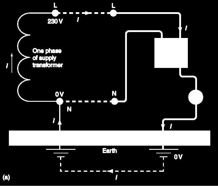
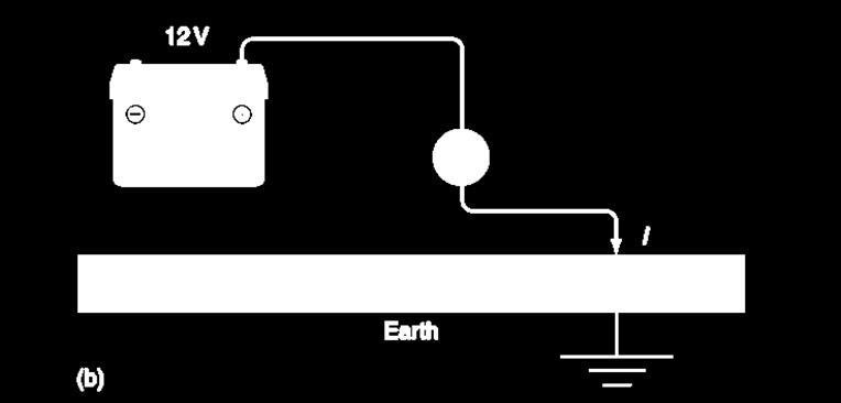
20 Earth Earth is not a good conductor So why connect anything to it? Understand of Potential Difference (PD) 0 volt potential! Earth: the conductive mass of earth, whose electric potential at any point is conventionally taken as zero Test: Measure voltage between Phase and Earth =? Measure voltage between 12V terminal of a battery and earth =? 20
21 illustration 21
22 Earth Person touching a faulty appliance could suffer an electric shock Lethal shock current level is 50mA and above Protection against electric shock is achieved by bonding all metallic parts between them: Ensures that under healthy conditions all metalwork is at 0 volts Under fault conditions, all metalwork rises to same potential Simultaneous contact with 2 such metal parts would not result in a dangerous shock no PD E.E.B. (A.D.S.) 22
23 Earth Earth presents a high resistance to the flow of current unless it is wet Resistance is enough to restrict fault current to a level well below that of the rating of the protective device leaving a faulty circuit uninterrupted methods to overcome discussed later. 23
24 Connecting to Earth Necessary to have as low an earth path resistance as possible The greater the surface contact area with earth that can be achieved, the better. Methods of connecting to earth Rod earth electrode (most popular, show data) Plates( sufficient depth needed, 1-2 m 2 ) Tapes (earthing of large electricity substations) 24

25 Shock Path 25

26 Earth electrode resistance area 26
27 Ground surface voltage 27

28 Housing the electrode in a pit below ground level 28

29 Earth Rod 29
30 Earthing in IEE regulations Chapter 4 Indirect contact contact with metalwork made live by a fault Can be overcome by EEBADS where we bond together and earth: All metalwork associated with electrical apparatus and systems, termed exposed conductive parts e.g conduit, trunking and metal cases of apparatus All metalwork liable to introduce potential, including earth potential, termed extraneous conductive parts e.g. gas, oil and water pipes, structural steelwork, radiators, sinks and baths 30
31 Earthing in IEE regulations Chapter 4 Conductors in such connections are called protective conductors, subdivided into: circuit protective conductors CPC Main equipotential bonding conductors Other equipotential bonding conductors Supplementary bonding conductors 31

32 Illustration of earthing and protective conductor terms 32
33 Earthing Systems T terre (French for earth) N neutral C combined S separate When letters above are grouped they form the earthing system classification 1 st how supply source is earthed 2 nd how metalwork of an installation is earthed 3 rd, 4 th indicate functions of neutral and protective conductors 33
34 34
35 Earthing Systems TN-S A TN-S system has the neutral of the source of energy connected with earth at one point only, at or as near as is reasonably practicable to the source, and the consumer s earthing terminal is typically connected to the metallic sheath or armour of the distributor s service cable into the premises or to a separate protective conductor of, for instance, an overhead supply 35

36 Earthing Systems TN-S 36
37 Earthing Systems TN-S 37

38 Earthing Systems TN-S 38
39 Earthing Systems TN-C-S A TN-C-S system has the supply neutral conductor of a distribution main connected with earth at source and at intervals along its run. This is usually referred to as protective multiple earthing (PME). With this arrangement the distributor s neutral conductor is also used to return earth fault currents arising in the consumer s installation safely to the source. To achieve this, the distributor will provide a consumer s earthing terminal which is linked to the incoming neutral conductor. 39

40 Earthing Systems TN-C-S 40

41 Earthing Systems TN-C-S 41

42 Earthing Systems TN-C-S 42
43 Protective multiple earthing (PME). Such a supply system is described in BS 7671 as TN-C-S The Electricity Safety, Quality and Continuity Regulations 2002 permit the distributor to combine neutral and protective functions in a single conductor provided that, in addition to the neutral to earth connection at the supply transformer, there are one or more other connections with earth. This protective multiple earthing (PME) has been almost universally adopted by supply companies in the UK as an effective and reliable method of providing their customers with an earth connection. Such a supply system is described in BS 7671 as TN-C-S. 43
44 Protective multiple earthing (PME). Such a supply system is described in BS 7671 as TN-C-S However, under certain supply system fault conditions (external to the installation) a potential can develop between the conductive parts connected to the PME earth terminal and the general mass of earth. Supply system There are multiple earthing points on the supply network, and providing bonding within the building complies with BS 7671 it is unlikely that such a potential as described above would in itself constitute a hazard. Additional earth electrode for PME supplies. In the unlikely event of the PEN conductor of the supply becoming open circuit, touch voltages perhaps causing some discomfort may arise on exposed metal in customers installations downstream of the open circuit. 44

45 Protective multiple earthing (PME). Such a supply system is described in BS 7671 as TN-C-S The effect can be mitigated by connection of a suitable earth electrode to the main earth terminal of the customers installation. The value of the resistance toearth necessary to limit the touch voltages to a given value depends on the load and the network parameters: 45
46 Protective multiple earthing (PME). Such a supply system is described in BS 7671 as TN-C-S Where: Vs is the nominal supply (source) voltage Vp is the touch voltage Re is the external supply resistance RL is the load resistance (Vs2/ wattage) RA is the resistance of the additional earth electrode including parallel earth (e.g. water and gas pipes) RB is the resistance to earth of the neutral point of the power supply. 46
47 Earthing Systems TT A TT system has the neutral of the source of energy connected as for TN-S, but no facility is provided by the distributor for the consumer s earthing. With TT, the consumer must provide his or her own connection to earth, i.e. by installing a suitable earth electrode local to the installation. 47

48 Earthing Systems TT 48

49 Earthing Systems TT 49

50 Earthing Systems TT 50
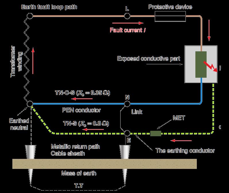
51 Earth fault loop impedance - Z s Circuit protection should operate in the event a direct fault from phase to earth Attention on speed of operation! Depends on magnitude of fault current which in turn depends on the impedance of the earth return path Path consists of 1. The cpc. 2. The consumer s earthing terminal and earth conductor. 3. The return path, either metallic or earth, dependent on the earthing system. 4. The earthed neutral of the supply transformer. 5. The transformer winding. 6. The line conductor from the transformer to the fault. 51
52 Earth fault loop impedance - Z s 52
53 53

54 Earth fault loop impedance Z s Simplified loop path Z s =Z e + R 1 + R 2 I = U oc / Z s 54
55 Determining Z e - external loop impedance 1. Determine it from details of the supply transformer, the main distribution cable and the proposed service cable 2. Measure it from the supply intake position of an adjacent building having service cable of similar size and length to that proposed 3. Use maximum likely values issued by the supply authority as follows (UK) 1. TT system: 21 Ω maximum? 2. TN-S system: 0.8 Ω maximum 3. TN-C-S system: 0.35 Ω maximum 55
56 Calculating resistance values at conductor operating temperature R t = R 20 { 1 + α 20 ( θ - 20 ) } Where, R t = Resistance at conductor operating temp R 20 = Resistance at 20 C α 20 = the 20 temp coefficient of copper, Ω/Ω/ C θ = the conductor operating temperature For 70 C PVC insulated conductor, the multiplier becomes { (70-20)}=1.2 56
57 Example For a 90 C XLPE type cable the multiplier becomes: 57

58 Copper conductor resistances 1-35 mm 2 58

59 Copper conductor resistances mm 2 59
60 Earth fault loop impedance - Z s Value of Z s should be as low as possible in order to allow enough current to flow to operate the protection as quickly as possible. Tables 41B1, B2 and D give maximum values of loop impedance for different sizes and types of protection for sockets and fixed equipment circuits 60
61 Earth fault loop impedance in 17 th edition- Z s Value of Z s should be as low as possible in order to allow enough current to flow to operate the protection as quickly as possible. Tables 41.2, 41.3 and 41.4 give maximum values of loop impedance for different sizes and types of protection for sockets and fixed equipment circuits 61
62 Disconnection times in 16 th edition Socket outlets 0.4 sec or less Circuits feeding fixed equipment 5 sec or less Bathrooms 0.4 sec or less These times do not indicate the duration that a person can be in contact with a fault. They are based on the probable chances of someone being in contact with exposed or extraneous conductive parts at the precise moment that a fault develops 62
63 Disconnection times in 17 th edition Final circuits 0.4 sec or less Distribution circuits 5 sec or less Bathrooms 0.4 sec or less These times do not indicate the duration that a person can be in contact with a fault. They are based on the probable chances of someone being in contact with exposed or extraneous conductive parts at the precise moment that a fault develops 63

64 Disconnection Times for final circuits not exceeding 32A 64

65 Disconnection Times 65
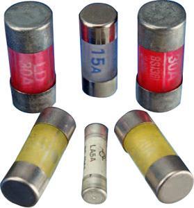
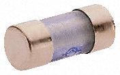
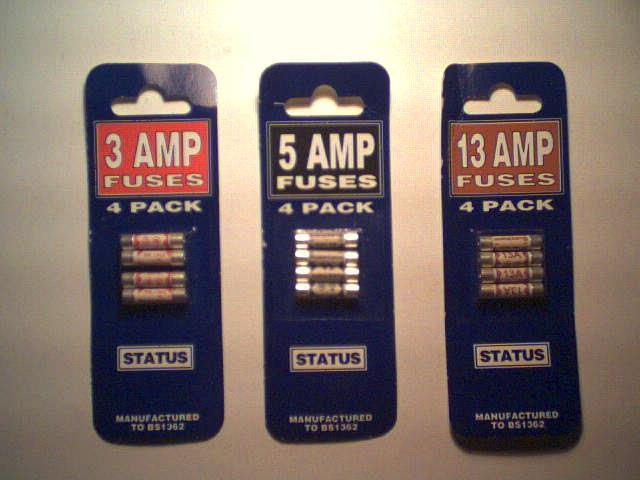

66 Fuses 66


67 Fuses BS3871 domestic cartridge fuse Description: Metal light switch which is not earthed. This poses a risk of shock. Note that the cables are old steel stranded and that their outer insulation is frayed and extremely worn 67
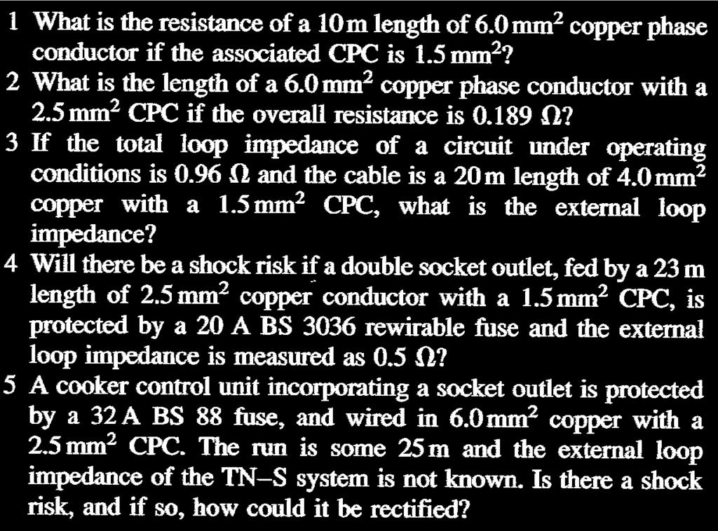
68 Example 1 68

69 Example 2 69

70 Example 2 - figure 70
71 Additional Protection (17 th edition) Requirements for RCD protection 30mA All socket outlets rated at not more than 20 A and for unsupervised general use Mobile equipment rated at not more than 32 A for use outdoors All circuits in a bath/shower room Preferred for all circuits in a TT system All cables installed less than 50mm from the surface of a wall or partition (in the safe zones) if the installation is unsupervised, and also at any depth if the construction of the wall or partition includes metallic parts 71
72 Additional Protection (17 th edition) In zones 0, 1 and 2 of swimming pool locations All circuits in a location containing saunas, etc. Socket outlet final circuits not exceeding 32A in agricultural locations Circuits supplying Class II equipment in restrictive conductive locations Each socket outlet in caravan parks and marinas and final circuit for houseboats All socket outlet circuits rated not more than 32 A for show stands, etc. All socket outlet circuits rated not more than 32 A for construction sites (where reduced low voltage, etc. is not used) All socket outlets supplying equipment outside mobile or transportable units All circuits in caravans All circuits in circuses, etc. A circuit supplying Class II heating equipment for floor and ceiling heating systems 72
73 Additional Protection (17 th edition) 100mA Socket outlets of rating exceeding 32A in agricultural locations. 300mA At the origin of a temporary supply to circuses, etc. Where there is a risk of fire due to storage of combustible materials All circuits (except socket outlets) in agricultural locations. 500mA Any circuit supplying one or more socket outlets of rating exceeding 32 A, on a construction site. 73
74 When max values of Z are not satisfied We have seen the importance of the total earth loop impedance Z in the reduction of shock risk. However, in some systems and especially TT, where the maximum values of Z given in Tables 41.2, 41.3 and 41.4 of the regulations may be hard to satisfy, an RCD may be used: its residual rating being determined from : I 50 / Z n s 74
75 Residual Current Devices Value of Z s is very important in the reduction of shock risk In TT systems, the earth forms part of the fault path and values given in tables 41B1,B2 and D may be hard to satisfy. In addition, climatic conditions alter the earth resistance, constituting Z s satisfactory in wet weather but not in dry! IEE regulations recommend protection for socket outlet circuits in TT systems be achieved by a residual operating device (RCD), such that the product of its residual operating current and the loop impedance will not exceed 50V RCBs, RCCBs, and RCDs are all the same thing RCBO is a combined circuit breaker and RCD in one device 75

76 RCD principle of operation Healthy circuit Same current through phase coil, load and neutral coil Magnetic effects of phase and neutral currents cancel out Faulty circuit phase to earth / neutral to earth Currents no longer equal Out of balance current produces residual magnetism in core and links with the turns of the search coil, inducing an emf in it. The emf drives a current in the trip coil causing operation of the device 76
77 Why do we need residual current devices? The standard method of protection is to make sure that an earth fault results in a fault current high enough to operate the protective device quickly so that fatal shock is prevented. However, there are cases where the impedance of the earth-fault loop, or the impedance of the fault itself, are too high to enable enough fault current to flow. In such a case, either: 1. - current will continue to flow to earth, perhaps generating enough heat to start a fire, or 2. - metalwork which is open to touch may be at a high potential relative to earth, resulting in severe shock danger. Either or both of these possibilities can be removed by the installation of a residual current device (RCD). In recent years there has been an enormous increase in the use of initials for residual current devices of all kinds. The following list, which is not exhaustive, may be helpful to readers: RCD residual current device RCCD residual current operated circuit breaker SRCD socket outlet incorporating an RCD PRCD portable RCD, usually an RCD incorporated into a plug RCBO an RCCD which includes overcurrent protection SRCBO a socket outlet incorporating an RCBO 77

78 RCD principle of operation Note: Phase to neutral fault will appear as a load and therefore RCD will not operate 3Φ RCD 78
79 Nuisance Tripping Certain appliances such as cookers, water heaters and freezers tend to have, the nature of their construction and use some leakage currents to earth Could cause operation of an RCD protecting entire installation Overcome by using split load consumer units, where socket outlets are protected by 30mA RCD, leaving all other circuits controlled by a normal mains switch In TT systems, is recommended to use a 100mA RCD for protecting circuits other than socket outlets Today, easy to protect any individual circuit with RCBO, making use of split load boards unnecessary 79
80 Nuisance Tripping Socket outlets intended for the connection of portable (φορητές) appliances outside the main equipotential zone require 30mA RCD. E.g. socket outlets in garages, lawn mowers, hedge trimmers 0.4sec disconnection time for any equipment outside main equipotential zone Exemption of RCD Fixed equipment connected via socket outlet (such as fridges) provided that some means of preventing the socket outlet being used for hand-held appliances is ensured 80
81 Supplementary Bonding Most debated topic in IEE regulations 1. Why do I need to bond the hot and cold taps and a metal sink together? Provided that main protective bonding conductors have been correctly installed there is no specific requirement in BS 7671 to do this. 81
82 Supplementary Bonding 2. Do I have to bond radiators in premises to for example, metal clad switches or socket outlets? Supplementary bonding is only necessary when extraneous conductive parts are simultaneously accessible with exposed conductive parts and the disconnection time for the circuit concerned cannot be achieved. In these circumstances the bonding conductor should have a resistance R 50/Ia Ia = is the operating current for the protection 82
83 Supplementary Bonding 3. Do I need to bond metal window frames? In general no. Apart from the fact that most window frames will not introduce a potential from anywhere, the part of the window most likely to be touched is the opening portion to which it would not be practicable to bond. There may be a case for the bonding if the frames were fortuitously touching structural steel work In any case there would need to be another simultaneously accessible part to warrant considering any bonding 83
84 Supplementary Bonding 4. What about bonding in bathrooms? Bathrooms are particularly hazardous areas with regards to shock risk, as body resistance is drastically reduced when wet. Hence supplementary bonding between exposed conductive parts must be carried out in addition to their CPCs. Also of course, taps and metal baths need bonding together and, to other extraneous and exposed conductive parts. 84
85 Supplementary Bonding 5. What size of bonding conductors should I use? Main protective bonding conductors should be not less than half the size of the main earthing conductor, subject to a minimum of 6mm 2 or where PME (TN-C-S) conditions are present, 10.0 mm 2. For example, most new domestic installations now have a 16.0 mm 2 earthing conductor, so all main bonding will be in 10.0 mm 2. Supplementary bonding conductors are subject to a minimum of 2.5 mm 2 if mechanically protected or 4.0 mm 2 if not. However, if these bonding conductors are connected to exposed conductive parts, they must be the same size as the cpc connected to the exposed conductive part, once again subject to the minimum sizes mentioned. It is sometimes difficult to protect a bonding conductor mechanically throughout its length, and especially at terminations, so it is perhaps better to use 4.0 mm 2 as the minimum size 85

86 Supplementary bonding in bathroom 86
87 Supplementary Bonding 5. What size of bonding conductors should I use? Main equipotential bonding conductors should be not less than half the size of the main earthing conductor, subject to a minimum of 6.0mm 2 or, for TNCS 10.0mm 2. For TT next figure Supplementary bonding conductors are subject to a minimum of 2.5mm 2 if mechanically protected or 4.0mm 2 if unprotected However, if these bonding conductors are connected to exposed conductive parts, they must be the same size as the CPC connected to the exposed conductive part, once again subject to the minimum sizes mentioned 87

 for TT")
88 Copper earthing conductor cross-sectional area (csa) for TT supplies 88
 for TN-S and TN-C-S supplies")
89 Earthing conductor and main protective bonding conductor sizes (copper equivalent) for TN-S and TN-C-S supplies 89

90 Supplementary bonding conductors 90
91 Supplementary Bonding 6. Do I have to bond free-standing metal cabinets, screens, workbenches etc? No. these items will not introduce a potential into the equipotential zone from outside, and cannot therefore be regarded as extraneous conductive parts 91
92 Supplementary Bonding 7. What are the bonding requirements for plumbing installations that incorporate plastic pipes? There is an increasing amount of plastic plumbing installations being used in modern houses for both domestic hot and cold water and C.H. systems. If the pipework is plastic but terminates in copper at taps, radiators etc. no bonding in needed 92

93 More examples 93
EARTHING YOUR QUESTIONS ANSWERED
 18 EARTHING YOUR QUESTIONS ANSWERED By Geoff Cronshaw What are earthed and unearthed systems? What are the requirements of BS 7671? What are the advantages and disadvantages of the various types of earthing
Electrical. Earthing & Bonding. Installation Techniques. Learning Notes MODULE 2.2 UNIT PHASE:2
 Electrical Learning Notes MODULE 2.2 UNIT 2.2.6 Installation Techniques Earthing & Bonding PHASE:2 Table of Contents INTRODUCTION... 3 DEFINITIONS... 4 EARTHING... 5 TYPES OF SYSTEM EARTHING... 10 EQUIPOTENTIAL
City & Guilds 2381 Test 2382 Level 3. Which one of these electrical installations does BS 7671:2008 not apply to:
 City & Guilds 2381 Test 2382 Level 3 Q1 Which one of these electrical installations does BS 7671:2008 not apply to: Temporary Construction sites Distributor s Equipment Caravans Public Premises Q2 Which
Working Principle of Earth Leakage Circuit Breaker (ELCB) and Residual Current Device (RCD)
 and Residual Current Device (RCD)") Working Principle of Earth Leakage Circuit Breaker (ELCB) and Residual Current Device (RCD) Schneider Electric RCBO Earth Leakage Circuit Breaker (ELCB) An Earth Leakage Circuit Breaker (ELCB) is a device
Working Principle of Earth Leakage Circuit Breaker (ELCB) and Residual Current Device (RCD) Schneider Electric RCBO Earth Leakage Circuit Breaker (ELCB) An Earth Leakage Circuit Breaker (ELCB) is a device
A guide for the connection of a low voltage installation to The Guernsey Electricity Network
 A guide for the connection of a low voltage installation to The Guernsey Electricity Network Guernsey Electricity Limited (GEL) - January 2017 2 Contents Definitions 3 Introduction 5 Scope 6 Sections 1
The impact of the 18 th Edition (BS 7671:2018) Sections 722, 753 and [new] 730
![The impact of the 18 th Edition (BS 7671:2018) Sections 722, 753 and [new] 730](/thumbs/89/98214988.jpg "The impact of the 18 th Edition (BS 7671:2018) Sections 722, 753 and [new] 730") The impact of the 18 th Edition (BS 7671:2018) Sections 722, 753 and [new] 730 In this article, Geoff Cronshaw looks at the impact that some of the proposed changes in the DPC (draft for public comment)
The impact of the 18 th Edition (BS 7671:2018) Sections 722, 753 and [new] 730 In this article, Geoff Cronshaw looks at the impact that some of the proposed changes in the DPC (draft for public comment)
SLOVAK UNIVERSITY OF TECHNOLOGY Faculty of Material Science and Technology in Trnava ELECTRICAL ENGINEERING AND ELECTRONICS.
 SLOVAK UNIVERSITY OF TECHNOLOGY Faculty of Material Science and Technology in Trnava ELECTRICAL ENGINEERING AND ELECTRONICS Róbert Riedlmajer TRNAVA 2007 Unit 14 - Fundamentals of power system protection
Electrical Installation Lecture No.14 Dr.Mohammed Tawfeeq Alzuhairi
 Earthing systems What is earthing? The whole of the world may be considered as a vast conductor which is at reference (zero) potential. In the UK it is referred to this as 'earth' whilst in the USA it
On_Disc. 2 o/c1 BS 7671 applies to a lift installations b highway equipment c equipment on board ships d electrical equipment of machines.
 1 PAPER 4 Sample Questions - C&G 2382 17th Edition full paper D 1 o/c 1 - A recommendation for the interval to the first periodic inspection shall be made by: a the installation electrician. b the main
On-Site Guide (BS 7671:2008 Wiring Regulations, incorporating Amendment No 1:2011)
") (BS 7671:2008 Wiring Regulations, incorporating Amendment No 1:2011) Author: IET Publications (edited by Mark Coles) Book details Author: IET Publications (edited by Mark Coles) Year: 2011 Format: Paperback,
(BS 7671:2008 Wiring Regulations, incorporating Amendment No 1:2011) Author: IET Publications (edited by Mark Coles) Book details Author: IET Publications (edited by Mark Coles) Year: 2011 Format: Paperback,
The Impact of the 18 th edition (BS 7671:2018)
") The Impact of the 18 th edition (BS 7671:2018) In this article, Geoff Cronshaw looks at some of the proposed changes in the DPC (draft for public comment) for electrical installations, focusing on Section
The Impact of the 18 th edition (BS 7671:2018) In this article, Geoff Cronshaw looks at some of the proposed changes in the DPC (draft for public comment) for electrical installations, focusing on Section
Key elements of the AS3000 Wiring standards and some of the recent changes.
 Key elements of the AS3000 Wiring standards and some of the recent changes. Dean of Engineering Steve Mackay Worked for 30 years in Industrial Automation 30 years experience in mining, oil and gas, electrical
ELECTRICIAN S THEORY EXAMINATION 19 June 2010 QUESTION AND ANSWER BOOKLET
 Candidate Code No. ET34 For Board Use Only Result Date Int Result Date Int ELECTRICIAN S THEORY EXAMINATION 19 June 2010 QUESTION AND ANSWER BOOKLET INSTRUCTIONS READ CAREFULLY Time Allowed: Three hours
Low Voltage Power Supplies in Electrified Areas
 Low Voltage Power Supplies in Electrified Areas Synopsis This document mandates requirements for control of return and stray currents and the management of earthing for low voltage power supplies in electrified
Initial and Periodic Inspection and Testing of Electrical Installations ( ) Sample Test
 Sample Test") Initial and Periodic Inspection and Testing of Electrical Installations (2391-052) Sample Test Version 1.1 January 2018 Please note this is not a complete sample theory exam, this document consists of
Initial and Periodic Inspection and Testing of Electrical Installations (2391-052) Sample Test Version 1.1 January 2018 Please note this is not a complete sample theory exam, this document consists of
CLP POWER HONG KONG LIMITED. SUPPLY RULES March 2001
 CLP POWER HONG KONG LIMITED SUPPLY March 2001 ADVISORY SERVICE Advice concerning matters relating to the supply of electricity may be obtained free of charge from the Company. OTHER COMPANY PUBLICATIONS
Effective discrimination of protective devices
 Effective discrimination of protective devices In the event of a fault occurring on an electrical installation only the protective device nearest to the fault should operate,leaving other healthy circuits
GUIDELINES ON ELECTRICAL SAFETY AT WORKPLACES
 MINISTRY OF LABOUR, INDUSTRIAL RELATIONS AND EMPLOYMENT GUIDELINES ON ELECTRICAL SAFETY AT WORKPLACES Occupational Safety & Health Inspectorate These guidelines should be used with approved standards:
BS : C&G 2382 Outcomes 4
 BS7671 2008: C&G 2382 Outcomes 4 Outcome 4 Protection for safety The candidate will be able to: 4.1 Identify the differences between basic and fault protection 4.2 State means of protection against electrical
WIRING MATTERS SEPTEMBER 2018
 WIRING MATTERS SEPTEMBER 2018 The 18 th Edition (BS 7671:2018) launch - revisited This is the second of two articles on the launch of the 18 th Edition (BS 7671:2018). The first article covered electric
3 o/c 2 An area or temporary structure used for display, marketing or sales is defined as a a booth b a stand c an exhibition d a show.
 1 PAPER 7 Sample Questions - C&G 2382 17th Edition paper C 1 o/c 1 - BS 7671 relates to permanent and temporary installations for equipment on: a marinas. b ships. c equipment on aircraft. d railway traction
ELECTRICAL INSPECTOR EXAMINATION 18 November 2017 QUESTION AND ANSWER BOOKLET Time Allowed: Three hours
 Candidate Code No. IT 36 For Board Use Only Result Date Int Result Date Int ELECTRICAL INSPECTOR EXAMINATION 18 November 2017 QUESTION AND ANSWER BOOKLET Time Allowed: Three hours INSTRUCTIONS READ CAREFULLY
ELECTRICAL INSTALLER THEORY EXAMINATION 21 June 2014 QUESTION AND ANSWER BOOKLET
 Candidate Code No. EIN 08 For Board Use Only Result Date Int Result Date Int ELECTRICAL INSTALLER THEORY EXAMINATION 21 June 2014 QUESTION AND ANSWER BOOKLET INSTRUCTIONS READ CAREFULLY Time Allowed: Three
Guidance for Low Voltage Electrical Installations
 Guidance for Low Voltage Electrical Synopsis This document provides information in support of GI/RT7007 Low Voltage Electrical. Signatures removed from electronic version Submitted by Anne E Blakeney Standards
Consumer Units and the 17th Edition Product Focus. Meet the new regulations How to avoid confusion
 Consumer Units and the 17th Edition Product Focus Meet the new regulations How to avoid confusion How to Avoid the Confusion The Rules and Regulations Explained The advent of the New 17th Edition of the
Major changes within the New 18 th Edition Wiring Regulations announced by The IET
 Major changes within the New 18 th Edition Wiring Regulations announced by The IET BS 7671:2018 Requirements for Electrical Installations will be issued on 2 nd July 2018 and is intended to come into effect
Chapter P Residential and other special locations
 Chapter P Residential and other special locations 1 2 3 Contents Residential and similar premises 1.1 General P1 1.2 Distribution boards components P1 1.3 Protection of people P4 1.4 Circuits P6 1.5 Protection
ELECTRICIANS REGULATIONS EXAMINATION 25 June 2011
 ER42 Candidate Code No. For Board Use Only Result Date Result Date Int ELECTRICIANS REGULATIONS EXAMINATION 25 June 2011 Int QUESTION AND ANSWER BOOKLET INSTRUCTIONS READ CAREFULLY Time Allowed: Three
ELECTRICIAN S REGULATIONS EXAMINATION 26 June 2010
 Candidate Code No. Result Date Int For Board Use Only ER38 Version of AS/NZS 3000 used (tick ONE Box) 2000 2007 & Amend 1 ELECTRICIAN S REGULATIONS EXAMINATION 26 June 2010 QUESTION AND ANSWER BOOKLET
Earthing Principles. Symmetra PX 250/500 kw
 Earthing Principles Symmetra PX 250/500 kw Table of Contents Earthing Principles... 1 Decoding the Earthing Types... 1 TN Systems... 2 Characteristics... 2 Reference to IEC/EN 60364-4-41 413.1.3... 2
Class X Chapter 09 Electrical Power and Household circuits Physics
 EXERCISE- 9 (A) Question 1: Write an expression for the electrical energy spent in flow of current through an electrical appliance in terms of current, resistance and time. Solution 1: Electrical energy,
ELECTRICIANS REGULATIONS EXAMINATION 23 November 2013 QUESTION AND ANSWER BOOKLET
 ER54 Candidate Code No. For Board Use Only Result Date Result Date Int ELECTRICIANS REGULATIONS EXAMINATION 23 November 2013 QUESTION AND ANSWER BOOKLET Time Allowed: Three hours INSTRUCTIONS READ CAREFULLY
SELECT MEMBERSHIP NUMBER Full Installation 75% new and 25% alteration to exsisting
 The Electrical Contractors Association SELECT MEMBERSHIP NUMBER 15019 ELECTRICAL INSTALLATION CERTIFICATE (REQUIREMENTS FOR ELECTRICAL INSTALLATIONS - BS 7671 [IET WIRING REGULATIONS]) EI Copyright The
Electrical Awareness and Considerations
 Electrical Awareness and Considerations By David Taylor FIHE MIET IEng Objectives Awareness of specifications. Awareness of Distribution Network Operators (DNO) earthing arrangements. Awareness of basic
GT/TDINT100 Issue: 1 Date: SEP 1993 Page 1 of 11
 British Railways Board Group Standard Page 1 of 11 Part A Synopsis This Directive gives the general requirements of telecommunications earthing systems, and encompasses the requirements for the earthing
CHAPTER V RESIDENTIAL WIRING
 CHAPTER V RESIDENTIAL WIRING 5.1. THE SERVICE ENTRANCE Buildings and other structures receive the electrical energy through the service entrance. In residential wiring, the electric company supply this
ELECTRICIAN S THEORY EXAMINATION 11 September 2010 QUESTION AND ANSWER BOOKLET
 Candidate Code No. ET36 For Board Use Only Result Date Int Result Date Int ELECTRICIAN S THEORY EXAMINATION 11 September 2010 QUESTION AND ANSWER BOOKLET INSTRUCTIONS READ CAREFULLY Time Allowed: Three
IET Wiring Regulations (BS 7671:2008+A3:2015) - SECTION 717 MOBILE OR TRANSPORTABLE UNITS
 - SECTION 717 MOBILE OR TRANSPORTABLE UNITS") IET Wiring Regulations (BS 7671:2008+A3:2015) - SECTION 717 MOBILE OR TRANSPORTABLE UNITS 717.1 Scope The particular requirements of this section apply to a.c. and d.c. installations for mobile or transportable
IET Wiring Regulations (BS 7671:2008+A3:2015) - SECTION 717 MOBILE OR TRANSPORTABLE UNITS 717.1 Scope The particular requirements of this section apply to a.c. and d.c. installations for mobile or transportable
ES5. Candidate Code No. For Board Use Only. Result Date Int. Result Date Int
 ES5 Candidate Code No. For Board Use Only Result Date Int Result Date Int ELECTRICAL WORKERS REGISTRATION BOARD ELECTRONIC SECURITY THEORY/REGULATIONS EXAMINATION 19 November 2005 QUESTION AND ANSWER BOOKLET
ELECTRICAL INSPECTOR EXAMINATION 14 November 2015 QUESTION AND ANSWER BOOKLET Time Allowed: Three hours
 Candidate Code No. IT 32 For Board Use Only Result Date Int Result Date Int ELECTRICAL INSPECTOR EXAMINATION 14 November 2015 QUESTION AND ANSWER BOOKLET Time Allowed: Three hours INSTRUCTIONS READ CAREFULLY
ELECTRICIANS REGULATIONS EXAMINATION 30 June 2012 QUESTION AND ANSWER BOOKLET
 ER47 Candidate Code No. For Board Use Only Result Date Result Date Int ELECTRICIANS REGULATIONS EXAMINATION 30 June 2012 QUESTION AND ANSWER BOOKLET INSTRUCTIONS READ CAREFULLY Int Time Allowed: Three
ELECTRICIANS REGULATIONS EXAMINATION 29 June 2013 QUESTION AND ANSWER BOOKLET
 ER52 Candidate Code No. For Board Use Only Result Date Result Date Int ELECTRICIANS REGULATIONS EXAMINATION 29 June 2013 QUESTION AND ANSWER BOOKLET Time Allowed: Three hours INSTRUCTIONS READ CAREFULLY
Range 16A to 63A. Sensitivity 30mA, 100mA, 300mA, 500mA. Execution Double Pole, Four Pole. Specification IEC / IS : 2000
 The flow of current through electrical facilities always involves risks. Poorly insulated equipment, faulty wires and incorrect use of an electrical devise cause currents to flow through the wrong path
ES5 Security Theory/Regulations Answer Schedule
 ES5 Security Theory/Regulations Answer Schedule Notes:1. means that the preceding statement/answer earns 1 mark. 2. This schedule sets out the expected answers to the examination questions. The marker
ELECTRICAL INSTALLER EXAMINATION 18 November 2017 QUESTION AND ANSWER BOOKLET
 Candidate Code No. EIN15 For Board Use Only Result Date Int Result Date Int ELECTRICAL INSTALLER EXAMINATION 18 November 2017 QUESTION AND ANSWER BOOKLET INSTRUCTIONS READ CAREFULLY Time Allowed: Three
FINAL-ER 42 Electrician Regulations Answer Schedule
 FINAL-ER 42 Electrician Regulations Answer Schedule Notes:1. (1 mark) means that the preceding statement/answer earns 1 mark. 2. This schedule sets out the expected answers to the examination questions.
Level 3 Award in the Requirements for Electrical Installations BS 7671:2018 ( )
") Level 3 Award in the Requirements for Electrical Installations BS 7671:2018 (2382-18) March 2018 Version 1.0 FAQs 1 18 th Edition IET Wiring Regulations 2018 FAQs When will the 18 th Edition of BS 7671
Level 3 Award in the Requirements for Electrical Installations BS 7671:2018 (2382-18) March 2018 Version 1.0 FAQs 1 18 th Edition IET Wiring Regulations 2018 FAQs When will the 18 th Edition of BS 7671
Calculation of the Cross-sectional Areas of Circuit Live Conductors
 Calculation of the Cross-sectional Areas of Circuit Live Conductors MOTOR CIRCUITS SUBJECT TO FREQUENT STOPPING AND STARTING Regulations requires that where a motor is intended for intermittent duty and
RESIDUAL CURRENT CIRCUIT BREAKER
 Quality Features Mid Trip - Different knob position to indicate whether the device is Switched OFF by a fault or Switched OFF manually Inscription Window - Ensures circuit identification and hence reduces
WIRING DESIGN & PROTECTION REQUIREMENTS CHECKLIST
 WIRING DESIGN & PROTECTION REQUIREMENTS CHECKLIST Use & Identification of Grounded and Grounding Conductors YES NO N/A Grounded conductors are identifiable and distinguishable from all other conductors.
Distribution of Supplies in Buildings
 Chapter 5 Distribution of Supplies in Buildings This chapter describes some of the points a designer will need to consider when planning an electrical installation. 5.1 INCOMING SUPPLY In the United Kingdom
Wilkins Safety Group
 H & S Guidance - Electricity INTRODUCTION Each year there are almost 1000 reportable accidents at work due to contact with electricity including a significant number of fatalities (about 20 a year). Even
Arc Fault Circuit Interrupter (AFCI) FACT SHEET
 FACT SHEET") Arc Fault Circuit Interrupter (AFCI) FACT SHEET THE AFCI The AFCI is an arc fault circuit interrupter. AFCIs are newly-developed electrical devices designed to protect against fires caused by arcing faults
Arc Fault Circuit Interrupter (AFCI) FACT SHEET THE AFCI The AFCI is an arc fault circuit interrupter. AFCIs are newly-developed electrical devices designed to protect against fires caused by arcing faults
1 This instrument must only be used by a competent and trained person and operated in strict accordance with the instructions.
 1 This instrument must only be used by a competent and trained person and operated in strict accordance with the instructions. KYORITSU will not accept liability for any damage or injury caused by misuse
KEWTECH. KT56 digital multi function tester. Instruction manual
 KEWTECH KT56 digital multi function tester Instruction manual Contents 1 Safety Notice 1 2 Features and Principles of Measurement 3 3 Introduction 6 4 Specifications 7 5 Instrument layout 9 6 Operating
Electric Vehicle Charging Safety Guidelines Part 2: Selection and Installation Edition DRAFT
 Date of publication: 1 November 2016Not yet published Issued by: Mark Wogan, Manager Energy Safety WorkSafe New ZealandNot yet issued Electric Vehicle Charging Safety Guidelines Part 2: Selection and Installation
The University of New South Wales. School of Electrical Engineering and Telecommunications. Industrial and Commercial Power Systems Topic 6
 The University of New South Wales School of Electrical Engineering and Telecommunications Industrial and Commercial Power Systems Topic 6 PROTECTIONS 1 FUNCTION OF ELECTRICAL PROTECTION SYSTEMS Problems:
Electrical Safety Part I
 Electrical Safety Part I Mains voltage electricity is extremely dangerous. There is a significant risk of death through electrocution if mains voltage electricity is allowed to pass through the body. There
Reviewed: DD Month University Code of Practice for Electrical Safety. PART B - Design and Construction of Electrical Equipment within the University
 Safety Office Reviewed: 17 July 2012 Reviewed: DD Month University Code of Practice for Electrical Safety PART B - Design and Construction of Electrical Equipment within the University The purpose of this
Electrical Protection
 Electrical Protection Excessive current in any electrical circuit is hazardous and not desired, and these maybe caused by the following; 1. Overloads, and 2. Short-circuits. Overload Currents: These are
Electric Vehicle Charging Safety Guidelines Part 2: Selection and Installation
 86 Customhouse Quay PO Box 165, Wellington 6140 New Zealand Date of publication: 1 November 2016 Issued by: Mark Wogan, Manager Energy Safety WorkSafe New Zealand Electric Vehicle Charging Safety Guidelines
ELECTRICIAN S THEORY EXAMINATION 21 June 2014 QUESTION AND ANSWER BOOKLET
 Candidate Code No. ET49 For Board Use Only Result Date Int Result Date Int ELECTRICIAN S THEORY EXAMINATION 21 June 2014 QUESTION AND ANSWER BOOKLET INSTRUCTIONS READ CAREFULLY Time Allowed: Three hours
ECET Distribution System Protection. Overcurrent Protection
 ECET 4520 Industrial Distribution Systems, Illumination, and the NEC Distribution System Protection Overcurrent Protection One of the most important aspects of distribution system design is system protection.
Chapter 21 Practical Electricity
 Chapter 21 Practical Electricity (A) Electrical Power 1. State four applications of the heating effect of electricity. Home: o Used in electric kettles o Used in electric irons o Used in water heaters
EDS CUSTOMER LV INSTALLATION EARTHING DESIGN
 Document Number: EDS 06-0017 Network(s): Summary: ENGINEERING DESIGN STANDARD EDS 06-0017 CUSTOMER LV INSTALLATION EARTHING DESIGN EPN, LPN, SPN This standard provides guidance on the earthing of customer
The Management of Electrical Safety in Quarries, Associated Plant and Equipment
 Quarries National Joint Advisory Committee (QNJAC) Plant Information Sheet 1 (Version 1, November 2015, review date: 2020) The Management of Electrical Safety in Quarries, Associated Plant and Equipment
Electrical safety and you
 Electrical safety and you Electrical safety and you Introduction Electricity can kill. Each year about 1000 accidents at work involving electric shock or burns are reported to the Health and Safety (HSE).
Electrical Workplace Safety
 Electrical Workplace Safety Alan Kelly 23 rd September 2015 Objectives To provide an understanding of Electrical terms and the concepts of electricity To introduce Electrical Protective Devices and provide
Safe, fast HV circuit breaker testing with DualGround technology
 Safe, fast HV circuit breaker testing with DualGround technology Substation personnel safety From the earliest days of circuit breaker testing, safety of personnel has been the highest priority. The best
Trade of Metal Fabrication. Module 1: Basic Fabrication Unit 15: Electricity Phase 2
 Trade of Metal Fabrication Module 1: Basic Fabrication Unit 15: Electricity Phase 2 Table of Contents List of Figures... 5 List of Tables... 6 Document Release History... 7 Module 1 Basic Fabrication...
CHAPTER 2: ELECTRICAL SAFETY
 CHAPTER 2: ELECTRICAL SAFETY 2.1 Physiological Effect of Electricity 2.2 Macroshock and Microshock Macroshock Microshock 2.3 Approaches toward Protection against Shock 2.4 Medical Safety Test Electrical
SUPPLEMENTAL CORRECTION SHEET FOR SOLAR PHOTOVOLTAIC SYSTEMS - ELECTRICAL
 SUPPLEMENTAL CORRECTION SHEET FOR SOLAR PHOTOVOLTAIC SYSTEMS - ELECTRICAL This is intended to provide uniform application of the codes by the plan check staff and to help the public apply the codes correctly.
Fault Finding. Standard/Fundamental Faults
 Fault Finding There is a generally recognised method of approaching faultfinding, which is referred to as the 5-Point Fault Finding approach... the most important factor in this method concerns attaining
Unified requirements for systems with voltages above 1 kv up to 15 kv
 (1991) (Rev.1 May 2001) (Rev.2 July 2003) (Rev.3 Feb 2015) (Corr.1 June 2018) Unified requirements for systems with voltages above 1 kv up to 15 kv 1. General 1.1 Field of application The following requirements
part three electrical installations
 part three electrical installations Cleat Hitch Faulty electrics, or poorly installed electrical systems, can be a real hazard and could place you and others at risk. This part of the Standards aims to
ELECTRICAL. 60 Minutes
 ELECTRICAL 60 Minutes AGENDA Electrical definitions Electrical shocks, burns and secondary injuries Electrical hazards in the workplace Safety devices and prevention steps Do s and Don ts INTRODUCTORY
Service Entrance Methods
 Service Section Typical switchboards consist of a service section, also referred to as the main section, and one or more distribution sections. The service section can be fed directly from the utility
2000 Cooper Bussmann, Inc. Page 1 of 9 10/04/00
 DO YOU KNOW THE FACTS ABOUT SINGLE-POLE INTERRUPTING RATINGS? YOU MAY BE IN TROUBLE! Typical plant electrical systems use three-phase distribution schemes. As an industry practice, short-circuit calculations
MECKLENBURG COUNTY. Land Use and Environmental Service Agency Code Enforcement 2/8/12 ELECTRICAL CONSISTENCY MEETING. Code Consistency Questions
 MECKLENBURG COUNTY Land Use and Environmental Service Agency Code Enforcement 2/8/12 ELECTRICAL CONSISTENCY MEETING Code Consistency Questions 1. I am inspecting a building addition. They have a 480V to
FACT SHEET Standard: Electrical Safety
 What is a Ground Fault Circuit Interrupter? FACT SHEET The ground-fault circuit interrupter, or GFCI, is a fast-acting circuit breaker designed to shut off electric power in the event of a ground-fault
CHAPTER II-1 D. Construction subdivision and stability, machinery and electrical installations
 Only the Danish version is authentic Notice D II-1 D 1 October 2002 Technical regulation on the construction and equipment, etc. of passenger ships on domestic voyages CHAPTER II-1 D Construction subdivision
EDS CUSTOMER LV INSTALLATION EARTHING DESIGN
 Document Number: EDS 06-0017 Network(s): Summary: ENGINEERING DESIGN STANDARD EDS 06-0017 CUSTOMER LV INSTALLATION EARTHING DESIGN EPN, LPN, SPN This standard provides guidance on the earthing of customer
Installation and Construction Notes for EVSE4
 Installation and Construction Notes for EVSE4 You need to read and understand this if you want to build an EVSE that will be safe and need to pass a building inspectors review. Before beginning this process
The Licensed Distribution Network Operators of Great Britain
 DCRP_12_04_07 The Licensed Distribution Network Operators of Great Britain A review of Engineering Recommendation G12/3 Requirements for the Application of Protective Multiple Earthing to Low Voltage Networks.
Instruction Manual. for Heating Cables and Cold Leads Type and Catalogue no and Hemstedt GmbH.
 Instruction Manual for Heating Cables and Cold Leads Type 68994- and 68997- Catalogue no. 68994- and 68997- Hemstedt GmbH Schleicherweg 19 D-74336 Brackenheim-Botenheim Phone +49 (7135) 9898-0 Fax +49
TEMPORARY ELECTRIC WIRING FOR CARNIVALS, CONVENTIONS, EXHIBITIONS, FAIRS AND SIMILAR USES
 INFORMATION BULLETIN / PUBLIC - ELECTRICAL CODE REFERENCE NO.: LAMC 93.0230 Effective: 3-24-69 DOCUMENT NO. P/EC 2002-006 Revised: 11-17-00 Previously Issued As: RGA #7-69 TEMPORARY ELECTRIC WIRING FOR
Spring Test 10 due 05/11/2013
 Spring Test 10 due 05/11/2013 Multiple Choice Identify the letter of the choice that best completes the statement or answers the question. 1. When installed in an agricultural building that houses livestock
Renewable sources of electricity a brief overview
 Micro generation 11 Renewable sources of electricity a brief overview THE SCOPE of the 17th Edition is wider and contains many new requirements, including additional requirements to ensure the safe connection
Candidate Handbook answers
 Candidate Handbook answers Progress check 7.1, p. 341 1. What must the electrical system installed in premises be suitable for? The purpose of the system; the building and environment. What is the role
90.2 Scope. The installation of electrical conductors, equipment and raceways for:
 NEC Generator Primer Rules on the installation of generators and transfer switches 1 90.2 Scope The installation of electrical conductors, equipment and raceways for: public and private premises Conductors
PROTECTION OF THE BRANCH CIRCUIT
 PROTECTION OF THE BRANCH CIRCUIT Branch circuit should always be protected from over current. Hence, an overall current devices shall be installed in all branch circuitries. Function of the over-current
Element C8.3 Installation, Use and Inspection of Electrical Systems
 .3 Installation, Use and Inspection of Electrical Systems Duty Holders Electricity at Work Regs 1989 EWR Employers and Self Employed Comply with regs as far as they are under their control Managers of
9. Non-Residential Services (Commercial, Industrial, and Agricultural)
") Section 9 2016 Electric Service Requirements, 3rd Edition Section 9 Non-Residential Services Directory Page 9.1 General Requirements 68 9.2 Direct-Connect Metering, Single Installations 69 9.3 Direct-Connect
Section 9 2016 Electric Service Requirements, 3rd Edition Section 9 Non-Residential Services Directory Page 9.1 General Requirements 68 9.2 Direct-Connect Metering, Single Installations 69 9.3 Direct-Connect
Technical Manual POD Point
 Technical Manual POD Point Solo Charger User Guide How to use your POD Point Solo It couldn t be easier. To start charging, plug in your car and wait for the light to go green. To end your charge at any
Spring Test 7 due 05/03/2013
 Spring Test 7 due 05/03/2013 Multiple Choice Identify the choice that best completes the statement or answers the question. 1. A raceway contains two 3-phase, 3-wire circuits that supply 38 ampere continuous
Electrical Safety. Recognizing & Controlling Hazards
 Electrical Safety Recognizing & Controlling Hazards Introduction Healthcare facilities, including hospitals, physician offices, laboratoratories, dental offices and beyond are vulnerable to a variety of
Chapter 14:08 Factories and Works (Electrical) Regulations, Chapter 14:08 Factories and Works (Electrical) Regulations, 1976
 Regulations, Chapter 14:08 Factories and Works (Electrical) Regulations, 1976") 1 Title Chapter 14:08 Factories and Works (Electrical) Regulations, 1976 2 Interpretation of terms 3 Fencing and enclosure 4 Notices 5 Safety precautions 6 Switch-boards 7 Portable electric tools and lights
1 Title Chapter 14:08 Factories and Works (Electrical) Regulations, 1976 2 Interpretation of terms 3 Fencing and enclosure 4 Notices 5 Safety precautions 6 Switch-boards 7 Portable electric tools and lights
An average of one worker is electrocuted on the job every day There are four main types of electrical injuries:
 Electrical Safety Introduction An average of one worker is electrocuted on the job every day There are four main types of electrical injuries: Electrocution (death due to electrical shock) Electrical shock
1.4. Product overview Memera consumer units and devices
 1.4 MEMT series Memera consumer units The Memera range of consumer units provide a broad scope of products to meet the requirements of the 17th edition of the wiring regulations. This well established
Chapter 4 Utility Systems Electrical
 Chapter 4 Utility Systems Electrical Utility Systems Electrical The electrical supply to your home begins outside, where you will see either an overhead feed and piping down the side of your home or (if