STM32 PMSM FOC SDK 4.2
|
|
|
- Julianna Chambers
- 5 years ago
- Views:
Transcription

1 STM32 PMSM FOC SDK 4.2 Hands-on workshop with hardware tools Rev 1.5
2 Objectives 2 The purpose of this hands-on workshop is to: Get you up and running with the STM32 PMSM FOC SDK using the ST MC Workbench with the final purpose of running a PM synchronous motor with STEVAL boards. Show you where to go for documentation, firmware libraries and application notes and additional ecosystem support Help you obtain additional technical support
3 Systems check 3 Everyone should have: A Windows laptop (XP, Vista or Win 7, Win 8) A ST-LINK dongle (optional) USB to RS-232 dongle and a null modem cable (optional) The permanent magnet motor you want to run A multimeter (optional) An oscilloscope with current probe (optional) An insulated DC and or AC power supply Ready to begin?

4 Hardware setup
5 Step #1 Hardware setup 5 It is possible to choose one of the following offers: Complete Motor Control Kit. One of the complete inverters currently in stock. Any STM32 evaluation board combined with one of the ST evaluation power stages both including the MC connector. The following slides report all available boards present in the ST stock that can be used to arrange a motor control system. Follow the instructions in the related user manual to set up each board.


6 Motor control board offer 6 MC kit Inverters Kit: from isolated debug probe to motor Control board Power board
 Value Line MCUs Yes Single drive STM3210B-MCKIT Motor control")
")

7 MC kit Motor control kits 7 Part Number Description ST Link on-board Type STM32100B-MCKIT Motor control starter kit for STM32F100 (128KB Flash) Value Line MCUs Yes Single drive STM3210B-MCKIT Motor control starter kit for STM32 (128KB flash) Performance and Access Line microcontrollers No Single drive P-NUCLEO-IHM001 STM32 Nucleo Pack FOC and 6-step control for Low voltage 3-ph motors Yes (embedded) Single drive The motor control kit connections represented below can also be applied when combining STM32 control boards and evaluation power boards. STM3210B-MCKIT STM32100B-MCKIT P-NUCLEO-IHM001 Serial communication RS232


8 Inverters ST complete inverters 8 Part Number Description ST Link on-board Type STEVAL-IHM034V2 Dual motor control and PFC demonstration board featuring the STM32F103 and STGIPS20C60 No Single/Dual drive STEVAL-IHM036V1 Low power motor control board featuring the SLLIMM STGIPN3H60 and MCU STM32F100C6T6B No Single drive STEVAL-IHM038V1 BLDC ceiling fan controller based on STM32 and SLLIMM-nano No Single drive STEVAL-IHM040V1 BLDC/PMSM driver demonstration board based on STM32 and the SLLIMM nano No Single drive STEVAL-IHM042V1 Compact, low-voltage dual motor control board based on the STM32F303 and L6230 Yes Single/Dual drive STEVAL-IHM043V1 6-Step BLDC sensorless driver board based on the STM32F051 and L6234 No Single drive STEVAL-IFN003V1 DC PMSM FOC motor drive No Single drive STEVAL-IHM034V2 STEVAL-IHM036V1 STEVAL-IHM042V1 STEVAL-IHM043V1 STEVAL-IFN003V1 STEVAL-IHM038V1 STEVAL-IHM040V1


9 Control board STM32 evaluation boards with MC connector 9 Part Number Description ST Link on-board Type STM32072B-EVAL Evaluation board with STM32F072VB MCU Yes Single drive STM3210E-EVAL Evaluation board for STM32 F1 series - with STM32F103 MCU No Single drive STM3220G-EVAL Evaluation board for STM32 F2 series - with STM32F207IG MCU Yes Single drive STM32303E-EVAL Evaluation board for STM32F303xx microcontrollers Yes Single/Dual drive STM3240G-EVAL Evaluation board for STM32F407 line - with STM32F407IG MCU Yes Single drive STEVAL-IHM022V1 High density dual motor control demonstration board based on the STM32F103ZE microcontroller No Single/Dual drive STEVAL-IHM039V1 Dual motor drive control stage based on the STM32F415ZG microcontroller No Single/Dual drive STM32072B-EVAL STM3220G-EVAL STM3240G-EVAL STM3210E-EVAL STEVAL-IHM022V1 STM32303E-EVAL STEVAL-IHM039V1 (1) Only necessary for high-voltage applications or if not included with the evaluation board: In-circuit debugger/programmer.. ST-LINK/V2 ST-LINK/V2-ISOL (2500 VRMS high isolation voltage)
10 Power board ST evaluation power boards with MC connector 10 Part Number STEVAL-IHM021V2 STEVAL-IHM023V3 STEVAL-IHM025V1 STEVAL-IHM028V2 STEVAL-IHM032V1 STEVAL-IHM035V2 STEVAL-IHM045V1 STEVAL-IPM05F (1) STEVAL-IPM07F (1) STEVAL-IPM10F (1) STEVAL-IPM10B (1) STEVAL-IPM15B (1) Note 1: Available Q4/15 Description 100 W, 3-phase inverter based on L6390 and UltraFASTmesh MOSFET for speed FOC of 3-phase PMSM motor drive 1 kw 3-phase motor control evaluation board featuring L6390 drivers and new IGBT STGP10H60DF 1 kw 3-phase motor control demonstration board featuring the IGBT SLLIMM STGIPL14K60 2 kw 3-phase motor control demonstration board featuring the IGBT intelligent power module STGIPS20C W inverter featuring the L639x and STGD3HF60HD for 1-shunt based sinusoidal vector control and trapezoidal scalar control 3-phase high voltage inverter power board for FOC and scalar motor control based on the STGIPN3H60 (SLLIMM -nano) 3-phase high voltage inverter power board for FOC based on the STGIPN3H60A (SLLIMM -nano) 3-phase motor control power board featuring STGIF5CH60TS-L 3-phase motor control power board featuring STGIF7CH60TS-L 3-phase motor control power board featuring STGIF10CH60TS-L 3-phase motor control power board featuring STGIB10CH60TS-L 3-phase motor control demonstration board featuring STGIB15CH60TS-L

, bootstrap capacitors, snubber capacitor,")

11 Flexible MC platform Power board Flexible approach: STEVAL-IPMxx 11 The STEVAL-IPMnmx evaluation board is a universal, fully-tested and populated-design consisting of a 3-phase inverter bridge based on the SLLIMM 2 nd series IPM. The main characteristics are small size, minimal BOM and high efficiency. It consists of an interface circuit (bus and V CC connectors), bootstrap capacitors, snubber capacitor, short-circuit protection, fault event circuit, temperature monitoring, single/three shunt resistors and filters for input signals. A double current sensing option is provided: three dedicated on-board op amps or by using the op amps embedded on MCU. Hall/encoder part completes the circuit.


 / encoder inputs (3.")
12 Hall/encoder sensors Flexible MC platform Power board STEVAL-IPMxx Features and architecture 12 Inverter evaluation board based on 2 nd series of ST s SLLIMM IPM trench-gate field-stop technology IGBT STGIxxCH60x full-molded or DBC package Input bus voltage: V DC Nominal power: from 300 W to 3 kw SLLIMM card Current capability: from 5 to 30 A (nominal) Hardware overcurrent protection using SLLIMM s Smart Shut Down Motor current sensing: single or three shunt configuration MC connector 3 shunt/single and network sensing V DC ST s MC connector compatible Two options for sensing: on-board op amps or the MCU s DC bus voltage sensing to MCU Hall sensors (3.3/5 V) / encoder inputs (3.3/5 V) to MCU Testing pins for all IPM signals +450 V DC Very compact size


13 Flexible MC platform Power board STEVAL-IPMnmx SLLIMM cards 13 TOP
14 Hardware key features 1/3 14 Reference / bundle Voltage Power Motor type / control type * ST parts Application focus STEVAL-IHM034V2 230 V AC Nominal Up to 1.3k W STEVAL-IHM036V V AC Up to 100 W PMSM, V DC FOC STEVAL-IHM038V V AC Up to 40 W STEVAL-IHM040V1 120/230 V AC nominal (60/50 Hz) Up to 100 W STEVAL-IHM042V V Up to 10 W STEVAL-IHM043V1 7 to 42 V DC Up to 35 W STEVAL-IFN003V V Up to 45 W PMSM, Dual Motor (FOC) + digital PFC PMSM, FOC PMSM/BLDC FOC/Six step PMSM, FOC Single/3 shunt BLDC Six-step motor control PMSM, FOC 1x STM32F103C8T6 1x STGIPS20C60 1x Viper16L 1x STM32F100C6 1x STGIPN3H60 1x Viper16 1x STM x STGIPN3H60 1x L6562A 1x STGIPN3H60 1x STM32F100C8T6 1x VIPer16 2x L6230 1x STM32F303 1x ST1S14 1x L6234 1x STM32F051C6T6 1x L78L33ACD 1x STM32F103C 1x L6230PD Complete drive: compressors, room air conditioning, Water pumps, dish washers, washing machines Complete drive: fans, ceiling fans, pumps. Complete drive: pumps, fans Complete drive: fans, blowers, toys Complete drive: pumps, security systems, ATMs. Complete drive: pumps, security systems, ATMs STEVAL-IFN004V V Up to 35 W BLDC Six-step motor control 1x STM8S 1x L6230Q Complete drive: pumps, security systems, ATMs
15 Hardware key features 2/3 15 Reference / bundle Voltage Power Motor type / control type * ST parts Application focus STEVAL-IHM021V2 120/230 V AC nominal (60/50 Hz) Up to 100 W PMSM/BLDC FOC/Six step 3 shunts 3x L6390 1x Viper12 6x STD5N52U Power board: water pumps, fans, dish washers, washing machines STEVAL-IHM023V V AC V DC Up to 1 kw PMSM/BLDC FOC/Six step Single/3 shunts 3x L6390 1x Viper16 7x STGP10H60DF Power board: pumps, compressors, washing machines and more STEVAL-IHM025V V AC V DC Up to 1 kw PMSM/BLDC FOC/Six step 1x STGIPL14K60 1x Viper16 1x STGP10NC60KD Power board: pumps, compressors, washing machines and more STEVAL-IHM028V V AC V DC Up to 2 kw PMSM/BLDC FOC/Six step single/3-shunt 1x STGIPS20C60 1x VIPer26LD 1x STGW35NB60SD Power board: pumps, compressors, air conditioning and more STEVAL-IHM032V1 230 V AC nominal 86 to 260 V AC Up to 150 W PMSM/BLDC FOC/Six step single/3-shunt 2x L6392D 1x L6391D 1x Viper12 6 x STGD3HF60HD Power board: pumps, compressors, fans, dish washers and more STEVAL-IHM035V2 120/230 V AC nominal Up to 100 W PMSM/BLDC FOC/Six step single-shunt 1x STGIPN3H60 1x VIPer16L Power board: pumps, compressors, fans, dish washers and more STEVAL-IHM045V V AC V DC Up to 100 W PMSM FOC Single/3-shunt 1x STGIPN3H60A 1x VIPer06L 1x TSV994 Power board: pumps, compressors, fans, dish washers and more
16 Reference / bundle NEW Voltage Hardware key features 3/3 Power STEVAL-IPM05F (1) V DC Up to 500 W STEVAL-IPM07F (1) V DC Up to 700 W STEVAL-IPM10F (1) V DC Up to 1 kw STEVAL-IPM10B (1) V DC Up to 1.5 kw STEVAL-IPM15B (1) V DC Up to 2 W Motor type / control type * PMSM/BLDC FOC/Six step 3shunts PMSM/BLDC FOC/Six step Single/3 shunts PMSM/BLDC FOC/Six step PMSM/BLDC FOC/Six step single/3-shunt PMSM/BLDC FOC/Six step single/3-shunt ST Parts 1 x STGIF5CH60TS-L 1x TSV994 1 x STGIF7CH60TS-L 1x TSV994 1 x STGIF10CH60TS-L 1x TSV994 1 x STGIB10CH60TS-L 1x TSV994 1 x STGIB15CH60TS-L 1x TSV994 Application focus Power board: water pumps, fans, dish washers and more Power board: water pumps, fans and more Power board: pumps, compressors, washing machines and more Power board: pumps, compressors, air conditioning and more Power board: pumps, compressors, fans, dish washers and more 16 Note 1: Available Q4 15
17 SDK workflow
18 SDK workflow 1/5 18 ST MC Workbench Open the ST MC Workbench and create a new project (see Step #6).
19 SDK workflow 2/5 19 ST MC Workbench SDK.h Parameter files User project (Source code) MC library project Generate the configuration (.h) files for the firmware library (see Step #9).
20 SDK workflow 3/5 20 ST MC Workbench SDK.h Parameter files User project OBJ.OBJ OBJ Linker EXE IDE (Source code) MC library project LIB Compile the FW library using available IDE (IAR, Keil) (see step #10).
21 SDK workflow 4/5 21 ST MC Workbench SDK.h Parameter files User project OBJ.OBJ OBJ Linker EXE IDE ST-LINK (Source code) MC library project LIB Flash the executable into the microcontroller using ST-LINK (see Step #10).
22 SDK workflow 5/5 22 ST MC Workbench Serial communication for "run-time" feedback SDK.h Parameter files User project OBJ.OBJ OBJ Linker EXE IDE ST-LINK (Source code) MC library project LIB Establish a real-time communication with the firmware using the monitor feature of ST MC Workbench to start the motor, set the speed and get feedback (see Step #12).
23 Software setup

24 Step #2 Software setup 24 Download and install the STM32 PMSM FOC SDK You can find it at and searching for part number STSW-STM32100 It contains both the firmware package and the ST MC Workbench (PC GUI) After installation, you will have the following new folders: ST MC Workbench FW package
 Keil Embedded Development Tools for ARM, Cortex-M... (http://www.keil.")
25 Step #3 IDE setup 25 An IDE (Integrated development environment) is required to compile, flash and debug the application. Two IDEs are supported: IAR EWARM and KEIL µvision. They are available at the following addresses: IAR Embedded Workbench for ARM - IAR Systems ( Keil Embedded Development Tools for ARM, Cortex-M... (

26 Step #4 ST-LINK installation 26 If the control board or the complete system doesn t embed the ST-LINK, a stand-alone dongle is required. In any case, you must install the ST-LINK driver that can be found in the ST website searching for part number ST-LINK/V2 or ST-LINK/V2-ISOL Click on Design Resources, download and install the STSW-LINK009

27 Step #4 ST-LINK installation 27 On the same page, download and install also the STSW-LINK004 STM32 ST-LINK utility (This will be required to flash the LCD FW code into the MCU).

28 Step #5 Connect ST-LINK 28 Using the USB cable, connect the control board with ST-LINK embedded (or the ST-LINK dongle) to the A male connector into your laptop. Wait for Windows to recognize the ST-Link device and follow any steps required to install the driver. Upon successful driver recognition, the ST-Link device should be fully enumerated in the Windows Device Manager as shown:

29 Step #5 Driver trouble-shooting Open Device Manager. 2. Right-click on the STM32 STLink Driver icon. 3. Select Update Driver Software.


30 Step #5 Driver trouble-shooting Select Browse my computer for driver software. 5. Select Let me pick from a list of device drivers of my computer. 6. Click Next.

31 Step #5 Driver trouble-shooting 31 The STMicroelectronics ST-Link dongle should be listed. 7. Click Next.

32 Step #5 Driver trouble-shooting 32 A warning message may appear. 8. Select Install this driver software anyway.

33 Step #5 Driver trouble-shooting 33 You should receive a message: Windows has successfully updated your driver software. Re-check Device Manager to ensure STMicroelectronics STLink dongle is functioning normally.
34 Set up workbench project
35 Step #6 Create a new WB project based on the ST evaluation board 35 Choose: New Project
36 Step #6 Create a new WB project based on the ST evaluation board 36 Choose: 1. Applications 1
37 Step #6 Create a new WB project based on the ST evaluation board 37 Choose: 2 2. Single or dual motor
38 Step #6 Create a new WB project based on the ST evaluation board 38 Choose: 3 3. Board approach: Choose if you are using Inverter, MC Kit or Power plus Control boards. Select the board used or create your own custom board.

39 Step #6 Create a new WB project based on the ST evaluation board 39 Choose: 4 4. Motor: Choose motor from a motor database. (You can save your motor parameters from your project.)
40 Step #6 or Create a new WB project based on an example project Choose the WB example project that best fits your needs. Choose the one with the same name of the ST evaluation board you are using, or choose the one with the same microcontroller you are using. 40

41 Step #6 Create a new WB project 41 Starting from the board selection or example project, the control stage parameters will be populated with the correct values. For a custom project, the user can set all the parameters. STM32303C-EVAL

42 Step #6 Set up power stage 42 Starting from the board selection or example project, the power stage parameters will be populated with the correct values. For a custom project, the user can set all the parameters.

43 Step #6 Set up drive parameters 43 Starting from the board selection according to the chosen application, drive parameters will be populated with the correct values. For a custom project, the user can set all the parameters. Applications
44 Step #6 Drive parameter tricks 44 In Drive settings, decrease cut-off frequency of torque and flux regulator down to 2000 rad/s if power stage current reading topology is single shunt. In Sensing enabling and FW protections, uncheck the sensing options not supported by power stage and check any Set intervention threshold to power stage xxx buttons. In Drive settings, initially set default target speed to at least 20% of maximum application speed. In additional features, start without any additional method (possible to add them later).

45 Step #6 Drive parameter tricks 45 In Drive settings, choose a correct PWM frequency and torque and flux execution rate in such a way that the FOC rate = PWM freq Execution rate maximum FOC rate according to the microcontroller used. is compatible with the STM32F4xx, STM32F3xx STM32F103x HD/XL, STM32F2xx STM32F103x LD/MD STM32F100x, STM32F0xx Motor Profiler 1shunt Flux Weakening IPMSM MTPA 3shunt Dual FOC Ne HFI (1) w Feed Forward Sensor-less (STO + PLL) Sensor-less (STO + Cordic) FreeRTOS F103, F2xx Max FOC (3) F103 ~23kHz F2xx ~40kHz Max FOC (3) F3xx ~ 30kHz F4xx ~50kHz Encoder ST MC Workbench support Hall sensors USART based com protocol add-on Startup on-the-fly Max FOC F100 ~11kHz F0xx ~12kHz ICS (2) Max FOC (3) ~23kHz Max Dual FOC (3) F103 ~20kHz F2xx ~36kHz Max Dual FOC (3) F3xx~27kHz F4xx~45kHz (1) High Frequency Injection (2) Supported only for STM32F103, STM32F2, STM32F4 (3) Max FOC estimated in sensorless mode
.")
46 Step #6 Drive parameter tricks 46 If motor profiler is not used, in start-up parameters, select the basic profile. Set current ramp initial and final values equal to motor nominal current value / 2 (if load is low at low speed, otherwise it can be set up to times nominal current value). Set speed ramp final value to around 30% of maximum application speed. According to motor inertia it may be required to increase the speed ramp duration. Set minimum start-up output speed to 15% of maximum application speed (if required, decreased it later). Set estimated speed band tolerance lower limit to 93.75% Enable the alignment at the beginning of your development (duration 2000 ms, final current ramp value from 0.5 to 1 times motor nominal current according to load) Basic
47 Step #7 Set up motor parameters 47 ST MC Workbench Motor section contains: Electrical motor parameters Motor sensor parameters In this hands-on session, we will configure the system for sensor-less control using a motor with a surface-mounted magnet. For a custom project, the user can set all the parameters.

48 Step #7 Set up motor parameters 48 If motor parameters are unknown (or instrumentation to measure them are missing), and if supported by the hardware, it is possible to use the new Motor Profiler feature. Example Hardware supporting the Motor Profiler (M.P.)
49 Step #7 Setup Motor Profiler 49 These parameters must be set by the user Motor pole pairs Maximum application speed Nominal speed of the motor will be computed and used to validate the maximum application speed selected by the user. Nominal current
50 Step #7 Setup Motor Profiler 50 Verify that the Motor Profiler check box is selected.

51 Step #7 Setup Motor Profiler 51 Choose the kind of load.
52 Step #7 Generate and compile the FW 52 Before running the Motor Profiler, execute Steps #9, #10 and #11 (#11 only if LCD is present in the board) to generate and compile the firmware. ST MC Workbench SDK.h Parameter files User project OBJ.OBJ OBJ Linker EXE IDE (Source code) MC library project LIB

53 Step #7 Run Motor Profiler 53 Using the ST MC Workbench, run the Motor Profiler procedure.
54 Step #7 Run Motor Profiler 54 To execute the Motor Profiler procedure, connect the PC to the microcontroller board via the USART connection. Connect the PC to the control board with the USB to RS-232 dongle (and a null modem cable). Select COM port and communication speed (as set in the Control Stage -> Digital I/O).

55 Step #7 Run Motor Profiler 55 Press Connect. Press Start.


56 Step #7 Run Motor Profiler 56 Procedure will end in about 60 seconds. Motor stopped Rs measurement Ls measurement Current regulators set-up 10 sec Open loop Ke measurement Sensorless state observer set-up Switch over 5 sec Closed loop Friction coefficient measurement Moment of inertia measurement Speed regulator set-up 45 sec

57 Step #7 Motor Profiler complete 57 At the end of the procedure, the measured parameters will be shown on a dedicated window. It is possible to import them on the workbench project and save them for later use.
58 Step #8 Set up motor parameters manually Select Surface Mounted PMSM in Motor Electrical parameters Magnetic structure. 58

59 Step #8 Set up motor parameters manually 59 Set Max Rated Speed with the maximum motor speed according the application specs. Set Nominal Current with maximum peak current provided to each of the motor phases according the motor specs. Set Nominal DC Voltage with value of DC bus provided to the inverter or the rectified value of AC input. Keep checked the Auto button near Demagnetizing Current.
 motor phases and provide up to 5% of the expected nominal DC bus voltage. (You may also set current protection to nominal motor current.")
60 Step #8 Set up motor parameters manually 60 Pole pair number The number of pole pairs is usually provided by the motor supplier, but in case it s not or if you d like to double check it: Connect a DC power supply between two (of the three) motor phases and provide up to 5% of the expected nominal DC bus voltage. (You may also set current protection to nominal motor current.) Rotate the motor with your hands, you should notice a little resistance, otherwise: If you are not able to rotate the motor, decrease the applied voltage. If the motor does not generate any resistance, gradually increase the applied voltage. The number of rotor stable positions in one mechanical turn represents the number of pole pairs. + - DC voltage source
61 Step #8 Set up motor parameters manually 61 Stator resistance and inductance Using the multimeter, measure the DC stator resistance phase-tophase (Rs) and divide it by two. Connect the DC voltage between two motor phases. Connect the oscilloscope voltage and current probes as shown in the figure. Increase the voltage up to the value where the current equals the nominal value, rotor with align. Don t move the rotor anymore. I V + - DC voltage source
62 Step #8 Set up motor parameters manually 62 Disable the current protection of DC voltage source. Stator resistance and inductance Unplug one terminal of the voltage source cable without switching it off. Plug the voltage source rapidly and monitor on the scope the voltage and current waveform until you get something like the one shown in the figure. The measurement is good if the voltage can be assimilated to a step and the current increase such as I * (1-e - t *L/R ). Measure the time required to current waveform to rise up to 63%. This time is Ld/Rs constant. Multiply it by Rs and you ll get Ld value. V I 0.63*I τ = L/R
63 Step #8 Set up motor parameters manually 63 Back EMF constant Ke The Back-EMF constant represents the proportionality constant between the mechanical motor speed and the amplitude of the B- EMF induced into the motor phases: V Bemf = K e ω mec To measure Ke, it usually suffices to turn the motor with your hands (or using a drill or another motor mechanically coupled) and use an oscilloscope to look for the phase-to-phase induced voltage (V Bemf ) + -
 Compute Ke in V RMS / K RPM : K e VBemf A [ V peak to peak] pole pairs number 1000 2 2 f [ Hz] 60 Bemf")
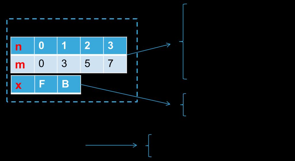
64 Step #8 Set up motor parameters manually 64 Back EMF constant Ke Measure the V Bemf frequency (f Bemf ) and the peak-to-peak amplitude (V Bemf A ) Compute Ke in V RMS / K RPM : K e VBemf A [ V peak to peak] pole pairs number f [ Hz] 60 Bemf
65 Generate, compile, debug and run


66 Step #10 Parameter generation 66 Once all the parameters have been entered in the ST MC Workbench, select the output path in the option form and choose SystemDriveParams present in the FW working folder. Click on the Generation button to configure the project.
. Select the correct user project from the drop-down menu according to the control stage used (e.g. STM32F10x_UserProject - STM3210B-EVAL). Compile and download.")
67 Step #11 Compile and program the MCU 67 Run the IAR Embedded Workbench. Open the IAR workspace (located in Project\EWARM) folder according to the microcontroller family (e.g. STM32F10x_Workspace.eww for STM32F1). Select the correct user project from the drop-down menu according to the control stage used (e.g. STM32F10x_UserProject - STM3210B-EVAL). Compile and download. Compile & program Select project
. Select the proper user project from the drop-down menu according to the control stage used (e.g. STM3210B-EVAL). Compile and download. Program Compile Select project")
68 Step #11 Compile and program the MCU 68 Optionally, run Keil uvision. Open the Keil workspace (located in Project\MDK-ARM) folder according to the microcontroller family (e.g. STM32F10x_Workspace.uvmpw for STM32F1). Select the proper user project from the drop-down menu according to the control stage used (e.g. STM3210B-EVAL). Compile and download. Program Compile Select project

.")
69 Step #12 Program LCD firmware 69 Run the ST-LINK Utility. File Open file and select the.hex file (located in LCDProject\hex) according to the control stage used (e.g. STM3210B-EVAL.hex). Target Program


70 Step #13 Run the motor 70 Arrange the system for running the motor: Connect the control board with the power board using the MC cable. Connect the motor to the power board. Connect the power supply to the power board and turn on the bus. If the board is equipped with the LCD: Press joystick center on Fault Ack button to reset the faults. Press joystick right until the Speed controller page is reached. The press joystick down to reach the Start/Stop button. Press the center of the joystick to run the motor.
.")

71 Step #13 Run the motor 71 Optionally you can start the motor using the ST MC Workbench. Connect the PC to the control board with the USB to RS-232 dongle (and a null modem cable). Open the Workbench project used to configure the firmware and click on Monitor button. Select the COM port and click Connect button. This establish the communication with the firmware. To clear the fault, click Fault Ack and then Start Motor button to run the motor. Monitor Connect Select COM port Start Fault ACK


72 Releasing your creativity with the STM32 72 st.com/e2e
Advanced BLDC Motor Drive and Control. Giovanni Tomasello Applications Engineer
 Advanced BLDC Motor Drive and Control Giovanni Tomasello Applications Engineer 3-Phase BLDC Motor-Control Block Diagram HV Only PFC Controllers (L49xx) Rectifiers (STTHxx, STPSxx) Power MOSFETs (Mdmesh
ST Motor Profiler (STM32 PMSM FOC SDK) Tips and Tricks
 Tips and Tricks") ST Motor Profiler (STM32 PMSM FOC SDK) Tips and Tricks ST Motor Profiler 2 What is the Motor Profiler tool? The Motor Profiler tool is a new algorithm able to automatically measure the electrical characteristics
ST Motor Profiler (STM32 PMSM FOC SDK) Tips and Tricks ST Motor Profiler 2 What is the Motor Profiler tool? The Motor Profiler tool is a new algorithm able to automatically measure the electrical characteristics
Quick Start Guide. Three-phase brushless DC motor driver expansion board based on L6230 for STM32 Nucleo (X-NUCLEO-IHM07M1)
") Quick Start Guide Three-phase brushless DC motor driver expansion board based on L6230 for STM32 Nucleo (X-NUCLEO-IHM07M1) Version 1.0 (September 18, 2015) Overview 2 1 Introduction to the STM32 Open Development
Quick Start Guide Three-phase brushless DC motor driver expansion board based on L6230 for STM32 Nucleo (X-NUCLEO-IHM07M1) Version 1.0 (September 18, 2015) Overview 2 1 Introduction to the STM32 Open Development
Quick Start Guide. Three-phase brushless DC motor driver expansion board based on L6230 for STM32 Nucleo (X-NUCLEO-IHM07M1)
") Quick Start Guide Three-phase brushless DC motor driver expansion board based on L6230 for STM32 Nucleo (X-NUCLEO-IHM07M1) Version 1.1.0 (May 16, 2016) Quick Start Guide Contents 2 X-NUCLEO-IHM07M1: Three-phase
Quick Start Guide Three-phase brushless DC motor driver expansion board based on L6230 for STM32 Nucleo (X-NUCLEO-IHM07M1) Version 1.1.0 (May 16, 2016) Quick Start Guide Contents 2 X-NUCLEO-IHM07M1: Three-phase
Welcome to ABB machinery drives training. This training module will introduce you to the ACS850-04, the ABB machinery drive module.
 Welcome to ABB machinery drives training. This training module will introduce you to the ACS850-04, the ABB machinery drive module. 1 Upon the completion of this module, you will be able to describe the
Freescale Semiconductor, I
 M68HC08 Microcontrollers 8-Bit Software Development Kit for Motor Control Targeting the MC68HC908MR32 SDKMR32UG/D Rev. 1, 11/2002 MOTOROLA.COM/SEMICONDUCTORS 8-Bit Software Development Kit for Motor Control
STEVAL-IHM028V2. 2 kw 3-phase motor control evaluation board featuring the STGIPS20C60 IGBT intelligent power module. Description.
 2 kw 3-phase motor control evaluation board featuring the STGIPS20C60 IGBT intelligent power module Data brief Features Complete solution for a 2 kw power inverter HV supply mode: voltage 90 VAC to 285
Solutions for Low Voltage and High Voltage Drives
 Solutions for Low Voltage and High Voltage Drives DC Motor Control Shield for Arduino & 750W Fan Demo with XMC1300, EiceDRIVER & IGBTs Electronica 2014, Munich Low & High Voltage Drives Markets & Example
TUTORIAL Motor Control Design Suite
 TUTORIAL Motor Control Design Suite April 2017 1 The Motor Control Design Suite provides a total solution for motor drive system design. From system specifications, the Motor Control Design Suite automatically
General Purpose Permanent Magnet Motor Drive without Speed and Position Sensor
 General Purpose Permanent Magnet Motor Drive without Speed and Position Sensor Jun Kang, PhD Yaskawa Electric America, Inc. 1. Power consumption by electric motors Fig.1 Yaskawa V1000 Drive and a PM motor
Permanent Magnet Synchronous Motor. High Efficiency Industrial Motors
 VoltPro is a new industrial motor range to meet high efficiency needs of industry by higher level of IE4 efficiency class. Main advantage of this product is cost effective solution ensured by using standard
BAC2000ind.
 DESCRIPTION ASI is a leader in the supply of industrial grade motor controllers with roots in electric vehicle technology dating back over 20 years. The is a high power density electric vehicle controller
Modern Motor Control Applications and Trends Tomas Krecek, Ondrej Picha, Steffen Moehrer. Public Information
 Modern Motor Control Applications and Trends Tomas Krecek, Ondrej Picha, Steffen Moehrer Content Introduction Electric Machines Basic and Advance Control Techniques Power Inverters and Semiconductor Requirements
STSPIN Motor Drivers. Selection guide.
 STSPIN Motor Drivers Selection guide www.st.com/stspin ST, a pioneer in the field of motor and motion control, offers a wide selection of ICs to best match an application spectrum covering a wide range
XMC1000 / XMC4400 Motor Control Application Kit
 XMC1000 / XMC4400 Motor Control Application Kit Getting Started 2 BLDC Motor Block Commutation with 3 Hall Sensor App (BLDCBCH03) Contents Motor Control Application Kit Composition Getting Started Development
When you finish the running, power off the receiver BEFORE turning off the transmitter.
 Thanks for purchasing Turnigy AQUASTAR ESC speed controllers. Turnigy AQUASTAR ESC are specifically developed to supply stable and strong power for r/c model boats beyond you expected. Please read the
AC Induction Motor Controller with VCL
 Motor Controllers AC Induction Motor Controller with VCL www.curtisinstruments.com 1 The Ultimate Class III Truck Control System: Superb Performance and Value This new AC induction motor controller (inverter)
CENTROIDTM. AC Brushless Drive. Product Spec Sheet
 4 Axis, up to 2 KW motors Brake Output for each axis Overtemp and Overcurrent Protection All-software Configuration Self-cooled Fiber Optic Control CENTROIDTM AC Brushless Drive Product Spec Sheet AC Brushless
APPLICATION NOTE
 12/18/02 Getting started using with a brushless motor Problem: For new users of an intelligent drive, starting to implement a motion control application can be a quite complex task. You need to know how
Introduction The aim of this application note is to outline how to configure an ACSM1 drive to run with an ABB BSM series AC servo motor.
 Motion Control Products Application note Configuring ACSM1 for use with BSM series servo motors The ABB ACSM1 AC servo drive can provide basic speed or torque control modes as well as versatile motion
EXPERIMENTAL VERIFICATION OF INDUCED VOLTAGE SELF- EXCITATION OF A SWITCHED RELUCTANCE GENERATOR
 EXPERIMENTAL VERIFICATION OF INDUCED VOLTAGE SELF- EXCITATION OF A SWITCHED RELUCTANCE GENERATOR Velimir Nedic Thomas A. Lipo Wisconsin Power Electronic Research Center University of Wisconsin Madison
Qingdao Zener Electric Co., Ltd
 Traction inverter, Power Supply, Emergency ventilation inverter for Light rail train Qingdao Zener Electric Co., Ltd Part 1 Power Supply for the Overhead Traction Line Introduction Conventional power supply
SINUS PENTA 2T/4T SINUS PENTA 2T/4T
 SINUS PENTA 2T/4T SINUS PENTA 2T/4T Technical Highlights One product, 5 integrated functions - IFD (Inverter Frequency Drive): vector modulation function for general-purpose applications (V/F pattern).
M o t o r C o n t r o l l e r s
 Motor Controllers Sensitron 221 West Industry Court Deer Park, NY 11729-4681 Phone (631) 586 7600 Fax (631) 242 9798 World Wide Web - www.sensitron.com E-mail - sales@sensitron.com 146-1109 Total Motion
SINAMICS GM150 IGCT version
 /2 Overview /2 Benefits /2 Design /6 Function /8 Selection and ordering data /8 Options Technical data /14 General technical data /15 Control properties /15 Ambient conditions /16 Installation conditions
Power Electronics & Drives [Simulink, Hardware-Open & Closed Loop]
![Power Electronics & Drives [Simulink, Hardware-Open & Closed Loop]](/thumbs/72/67745658.jpg "Power Electronics & Drives [Simulink, Hardware-Open & Closed Loop]") Power Electronics & [Simulink, Hardware-Open & Closed Loop] Project code Project theme Application ISTPOW801 Estimation of Stator Resistance in Direct Torque Control Synchronous Motor ISTPOW802 Open-Loop
Power Electronics & [Simulink, Hardware-Open & Closed Loop] Project code Project theme Application ISTPOW801 Estimation of Stator Resistance in Direct Torque Control Synchronous Motor ISTPOW802 Open-Loop
Motor control Reference Guide
 Motor control Reference Guide Content Introduction...3 Brushed DC motors...4 Single-phase AC induction motors...9 Stepper motors...15 Switched reluctance motors...19 3-phase brushless motors...23 Universal
User Manual Solar Charge Controller 3KW
 User Manual Solar Charge Controller 3KW Version: 1.3 CONTENTS 1 ABOUT THIS MANUAL... 1 1.1 Purpose... 1 1.2 Scope... 1 1.3 SAFETY INSTRUCTIONS... 1 2 INTRODUCTION... 2 2.1 Features... 2 2.2 Product Overview...
G Prasad 1, Venkateswara Reddy M 2, Dr. P V N Prasad 3, Dr. G Tulasi Ram Das 4
 Speed control of Brushless DC motor with DSP controller using Matlab G Prasad 1, Venkateswara Reddy M 2, Dr. P V N Prasad 3, Dr. G Tulasi Ram Das 4 1 Department of Electrical and Electronics Engineering,
Planning and Commissioning Guideline for NORD IE4 Synchronous Motors with NORD Frequency Inverters
 Getriebebau NORD GmbH & Co. KG Getriebebau-Nord-Straße 1 22941 Bargteheide, Germany www.nord.com Planning and Commissioning Guideline for NORD IE4 Synchronous Motors with NORD Frequency Inverters General
Technical Explanation for Inverters
 CSM_Inverter_TG_E_1_2 Introduction What Is an Inverter? An inverter controls the frequency of power supplied to an AC motor to control the rotation speed of the motor. Without an inverter, the AC motor
EDG6000 Electronic Digital Governor
 INTRODUCTION GAC s digital governor is designed to regulate engine speed on diesel and gaseous fueled engines. When paired with a GAC actuator the EDG is a suitable upgrade for any mechanical governor
zub A Software Kernel for Servo Drives and Frequency Converters machine control AG
 A Software Kernel for Servo Drives and Frequency Converters zub machine control AG zub machine control AG Buzibachstrasse 31, CH-6023 Rothenburg, Switzerland Phone +41 41 54150-40 Fax +41 41 54150-49 info@zub.ch
Brushless dc motor (BLDC) BLDC motor control & drives
 BLDC motor control & drives") Brushless dc motor (BLDC) BLDC motor control & drives Asst. Prof. Dr. Mongkol Konghirun Department of Electrical Engineering King Mongkut s University of Technology Thonburi Contents Brushless dc (BLDC)
Brushless dc motor (BLDC) BLDC motor control & drives Asst. Prof. Dr. Mongkol Konghirun Department of Electrical Engineering King Mongkut s University of Technology Thonburi Contents Brushless dc (BLDC)
SP4 DOCUMENTATION. 1. SP4 Reference manual SP4 console.
 SP4 DOCUMENTATION 1. SP4 Reference manual.... 1 1.1. SP4 console... 1 1.2 Configuration... 3 1.3 SP4 I/O module.... 6 2. Dynamometer Installation... 7 2.1. Installation parts.... 8 2.2. Connectors and
8-bit. Application Note. Microcontrollers. AVR601: Atmel Modular Evaluation Kits for Motor Control Applications. 1.
 AVR601: Atmel Modular Evaluation Kits for Motor Control Applications 1. Introduction Following the success of the MC100 and MC200 motor control demonstration kits, Atmel is expanding the support for motor
Sensorless Control Of Ac Motor Drives Speed And Position Sensorless Operation
 Sensorless Control Of Ac Motor Drives Speed And Position Sensorless Operation We have made it easy for you to find a PDF Ebooks without any digging. And by having access to our ebooks online or by storing
SINAMICS SM150. 4/2 Overview. 4/2 Benefits. 4/2 Design. 4/6 Function. 4/8 Selection and ordering data. 4/8 Options
 /2 Overview /2 Benefits /2 Design /6 Function /8 Selection and ordering data /8 Options Technical data /1 General technical data /15 Control properties /15 Ambient conditions /16 Installation conditions
PowerFlex AC Drives Portfolio
 PowerFlex AC Drives Portfolio PUBLIC INFORMATION 1 Rev 5058-CO900E Copyright 2013 Rockwell Automation, Inc. All Rights Reserved. PUBLIC INFORMATION Copyright 2015 Rockwell Automation, Inc. All Rights Reserved.
Unidrive M600 High performance drive for induction and sensorless permanent magnet motors
 Unidrive M600 High performance drive for induction and sensorless permanent magnet motors 0.75 kw - 2.8 MW Heavy Duty (1.0 hp - 4,200 hp) 200 V 400 V 575 V 690 V Unidrive M600 features Easy click-in keypad
ELECTRIC MACHINES EUROLAB 0.3 kw
 index SINGLE-PHASE MOTORS SPLIT-PHASE MOTOR DL 30130 CAPACITOR MOTOR DL 30140 UNIVERSAL MOTOR DL 30150 REPULSION MOTOR DL 30170 THREE PHASE ASYNCHRONOUS MOTORS SQUIRREL CAGE THREE PHASE ASYNCHRONOUS MOTOR
Planning and Commissioning Guideline for NORD IE4 Motors with NORD Frequency Inverters
 Planning and Commissioning Guideline for NORD IE4 Motors with NORD Frequency Inverters General Information From their basic function, motors with efficiency class IE4 are synchronous motors and are suitable
Table of Contents. General Information...1. Components...2. Connection...4
 Table of Contents General Information... Components... Connection...4 Interface of Main Unit...4 Oscilloscope...5 Multimeter...5 Voltage, Current, Resistance, Duty Cycle, Frequency and Battery Voltage...5
 1 Network based Motion Control A maximum of 16 axes can be operated from a PC through RS- 485 communication. All of the Motion conditions are set through network and saved Flash ROM as a parameter. Motion
3-phase 400 V 0.4 to 630 kw. High Performance Multifunctional Inverter
 3-phase 400 V 0.4 to 630 kw High Performance Multifunctional Inverter The performance reaching the peak in the industry The performance reaching the peak in the industry FRENIC-MEGA is a high performance,
International Journal of Advance Research in Engineering, Science & Technology
 Impact Factor (SJIF): 4.542 International Journal of Advance Research in Engineering, Science & Technology e-issn: 2393-9877, p-issn: 2394-2444 Volume 4, Issue 4, April-2017 Simulation and Analysis for
For motors controlled
 STEVE PETERSON Technical Training Engineer Yaskawa America Inc., Waukegan, IL Electronically reprinted from November 20, 2014 Choosing the right CONTROL METHOD for VFDs For motors controlled by a variable
CHAPTER 4 MODELING OF PERMANENT MAGNET SYNCHRONOUS GENERATOR BASED WIND ENERGY CONVERSION SYSTEM
 47 CHAPTER 4 MODELING OF PERMANENT MAGNET SYNCHRONOUS GENERATOR BASED WIND ENERGY CONVERSION SYSTEM 4.1 INTRODUCTION Wind energy has been the subject of much recent research and development. The only negative
HBI 22. Integrated Three-phase Synchronous Drive
 HBI 22 Integrated Three-phase Synchronous Drive positioning capability up to 9 Watts rated output power with linear hall sensor system with or without parking brake Motor type Dimension L1 L2 HBI 223 125
APPLICATION GUIDE. Pure easiness for a wide range of applications ACS580 general purpose drives
 APPLICATION GUIDE Pure easiness for a wide range of applications ACS580 general purpose drives 2 APPLICATION GUIDE ACS580 PURE EASINESS FOR MANY PURPOSES Table of contents 3 Pure easiness for many applications
Evaluation boards & reference designs
 Evaluation s & reference designs Application concepts to go! November 2006 www.st.com/evals If you want to evaluate ST's Microcontrollers, Power and Analog product families for use in your new design,
INDEX 1 Introduction 2- Software installation 3 Open the program 4 General - F2 5 Configuration - F3 6 - Calibration - F5 7 Model - F6 8 - Map - F7
 SET UP MANUAL INDEX 1 Introduction 1.1 Features of the Software 2- Software installation 3 Open the program 3.1 Language 3.2 Connection 4 General - F2 4.1 The sub-folder Error visualization 5 Configuration
A Practical Primer On Motor Drives (Part 11): AC And DC Motor Types
: AC And DC Motor Types") A Practical Primer On Motor Drives (Part 11): AC And DC Motor Types by Ken Johnson, Teledyne LeCroy, Chestnut Ridge, N.Y. ISSUE: December 2016 In the previous part in this series, the basic principles
A Practical Primer On Motor Drives (Part 11): AC And DC Motor Types by Ken Johnson, Teledyne LeCroy, Chestnut Ridge, N.Y. ISSUE: December 2016 In the previous part in this series, the basic principles
PowerJet Sequential Injection INDEX. 1 Introduction 1.1 Features of the Software. 2- Software installation
 INDEX 1 Introduction 1.1 Features of the Software 2- Software installation 3 Open the program 3.1 Language 3.2 Connection 4 Folder General - F2. 4.1 The sub-folder Error visualization 5 Folder Configuration
Unidrive M700 Class leading performance with onboard real-time Ethernet
 Unidrive M Class leading performance with onboard real-time Ethernet. kw -.8 MW Heavy Duty (. hp -, hp) V V V 9 V Unidrive M features Easy click-in keypad connection Range of multi-language LCD keypads
Utilizing Kollmorgen Goldline Series Servo Motors with the AKD Drive
 Group Drives and Motors Date June 30 2017 Series AKD and Goldline Revised Element Group Application Revision F Element Mating Author M. Brown # Of Pages 18 Utilizing Kollmorgen Goldline Series Servo Motors
Cordless Drill Motor Control with Battery Charging Using Z8 Encore! F0830 Reference Design
 Application Note Cordless Drill Motor Control with Battery Charging Using Z8 Encore! F0830 Reference Design AN025504-0910 Abstract Currently, most hand-held electric drilling machines operating on batteries
Instruction of connection and programming of the VECTOR controller
 Instruction of connection and programming of the VECTOR controller 1. Connection of wiring 1.1.VECTOR Connection diagram Fig. 1 VECTOR Diagram of connection to the vehicle wiring. 1.2.Connection of wiring
AC Servodrives Bivector 300/500 Advanced solutions for automation
 AC Servodrives Bivector 300/500 Advanced solutions for automation ABB Automation Bivector Field Oriented Torque Control - optimal working point setting for maximum KT - robust control in flux weakening
ALTIVAR 58 AC Drives
 Class 8806 / 8839 / 8998 CONTENTS Schneider Electric Brands Page ALTIVAR 58 AC Drives............................................... 3 Drives Overview...................................................
SME S.p.A. Via della Tecnica, n Arzignano (VI) - ITALY Phone:+39 (0444) Fax: +39 (0444)
 - ITALY Phone:+39 (0444) Fax: +39 (0444)") AC Induction Motor Controller DATASHEET (Rev. 1.4: April 2015) SME S.p.A. Via della Tecnica, n 40 36071 Arzignano (VI) - ITALY Phone:+39 (0444) 470511 Fax: +39 (0444) 451803 www.grupposme.com Model AC-M1
AC Induction Motor Controller DATASHEET (Rev. 1.4: April 2015) SME S.p.A. Via della Tecnica, n 40 36071 Arzignano (VI) - ITALY Phone:+39 (0444) 470511 Fax: +39 (0444) 451803 www.grupposme.com Model AC-M1
Kelly HPM High Power Full Bridge Permanent Magnet DC Motor Controller User s Manual
 Kelly HPM High Power Full Bridge Permanent Magnet DC Motor Controller User s Manual HPM72601 HPM72801 HPM12401 HPM12601 HPM12801 HPM14301 HPM14501 HPM14701 Rev.3.4 Dec. 2016 Contents Chapter1 Introduction...
PSIM Tutorial. HEV Design Suite. April
 PSIM Tutorial HEV Design Suite April 2013-1 - The HEV Design Suite provides a one-stop solution from system specifications to a completely designed HEV powertrain system. Using predefined templates, the
Ginlong Solis US 4G PV Single-Phase String Inverters; 6 kw through 10 kw. Terence Parker Ginlong Technologies
 Ginlong Solis US 4G PV Single-Phase String Inverters; 6 kw through 10 kw Terence Parker terence.parker@ginlong-usa.com Ginlong Technologies 2 Ginlong Solis: A Global Market Leader in PV String Inverters
Delivering higher efficiency in motor drive applications
 Delivering higher efficiency in motor drive applications Simon Duggleby, Technical Marketing Manager, Electronics, RS Components Electric motors consume around half of all the electricity produced worldwide
Unidrive M400 Fast set-up and diagnostics with real-text display, integrated PLC and safety inputs
 Unidrive M400 Fast set-up and diagnostics with real-text display, integrated PLC and safety inputs 0.25 kw - 110 kw (0.33 hp - 150 hp) 100 V 200 V 400 V 575 V 690 V Unidrive M400 features Optional AI-485
TOWER MAXI T SINGLE CONVERSION ON LINE UPS SYSTEMS
 INSTRUCTION MANUAL TOWER MAXI T SINGLE CONVERSION ON LINE UPS SYSTEMS September 2000 TOWER UPS DISTRIBUTION (PTY) LTD 1 1. INTRODUCTION T A B L E O F C O N T E N T S 1.1 General Description... 3 1.2 Features...
Piktronik d. o. o. Cesta k Tamu 17 SI 2000 Maribor, Slovenia Fax:
 PIK tr nik Phone: +386-2-460-2250 Piktronik d. o. o. Cesta k Tamu 17 SI 2000 Maribor, Slovenia Fax: +386-2-460-2255 e-mail: info@piktronik.com www.piktronik.com Sensorless AC motor control for traction
Technical Specifications. Sentinel PRO 700 VA up to 3000 VA 1000 VA ER-2200 VA ER-3300 VA ER
 Technical Specifications Sentinel PRO 700 VA up to 3000 VA 1000 VA ER-2200 VA ER-3300 VA ER Sentinel PRO CONTENTS 1. GENERAL DESCRIPTION... 2 1.1. Main features of the UPS unit... 3 1.2. Standard Versions...
Quick Start Guide of CV50- ControlVIT Series
 ❶ Safety precautions Do not refit the inverter unauthorizedly; otherwise fire, electric shock or other injury may occur. Please install the inverter on fire-retardant material and keep the inverter away
ADJUSTABLE FREQUENCY CONTROLS SENSORLESS VECTOR CONTROL. Dual Rating. Technologies Inc. mgitech.com NRTL/C CERTIFIED
 ADJUSTABLE FREQUENCY CONTROLS SENSORLESS VECTOR CONTROL Dual Rating NRTL/C CERTIFIED Technologies Inc. mgitech.com Sensor/Sensorless Vector Control Dual current rated for constant and variable torque Auto
Yaskawa AC Drive L1000A Supplement to the L1000A Technical Manual No. SIEP C , SIEP C , and SIEP C
 Yaskawa AC Drive L1000A Supplement to the L1000A Technical Manual No. SIEP C710616 32, SIEP C710616 33, and SIEP C710616 38 Introduction This supplement to the L1000A Technical Manual describes features
Kelly HSR Series Motor Controller with Regen User s Manual V 3.3. Kelly HSR Opto-Isolated Series Motor Controller with Regen.
 Kelly HSR Opto-Isolated Series Motor Controller with Regen User s Manual HSR72601 HSR72801 HSR12401 HSR12601 HSR12901 HSR14301 HSR14501 HSR14701 Rev.3.3 Dec. 2011 Contents Chapter 1 Introduction... 2 1.1
Application Note: SyMAX Permanent Magnet Motor Simple Startup Procedure
 Application Note: SyMAX Permanent Magnet Motor Simple Startup Procedure Variable Frequency Drives Optimize Performance and Further Improve Efficiency by using Permanent Magnet Motor Control. AN.SYMAX.01,
HGM1780. Automatic Genset Controller USER MANUAL. Smartgen Technology
 HGM1780 Automatic Genset Controller USER MANUAL Smartgen Technology Smartgen Technology Co., Ltd No. 28 Jinsuo Road Zhengzhou Henan Province P. R. China Tel: 0086-371-67988888/67981888 0086-371-67991553/67992951
IRT 4000 AT-S/M/L. Technical Manual. quality IN MOTION. quality IN MOTION
 IRT quality IN MOTION www.irtsa.com 4000 AT-S/M/L Technical Manual IRT quality IN MOTION E2 0 8 4 1 5 September 2013-Rev. 5 UL Requirements Drives Series 2000 / 4000 AT 1. Field wiring terminal to use
Drive Fundamentals. Motor Control Bootcamp May 15-18, Copyright 2015 Rockwell Automation, Inc. All Rights Reserved. PUBLIC CO900H
 - 5058-CO900H Drive Fundamentals Motor Control Bootcamp May 15-18, 2017 How are these Devices Related? Variable frequency drives Variable speed drives Variable speed controllers Adjustable frequency drives
SolarPower. User Manual. Suitable Products: Three-phase grid-tie inverter with energy storage. Three-phase off-grid inverter
 SolarPower User Manual Suitable Products: Three-phase grid-tie inverter with energy storage Three-phase off-grid inverter Management Software for Solar Inverter Table of Contents 1. SolarPower Overview...
ATOTH-G Series BLDC Motor Controller. User s Manual
 ATOTH-G Series BLDC Motor Controller User s Manual Contents Chapter One Summary...1 Chapter Two Main Features and Specifications.2 2.1 Basic Functions...2 2.2 Features... 5 2.3 Specifications...6 Chapter
VFD E Series. Features
 VFD E Series Output Frequency : 0.1 ~ 600 Hz. Built in PLC Function 500 Step program in Ladder Language. Side by side installation. Easy maintenance. Modular & Compact Design. Built-in MODBUS communication.
DYNEO VARIABLE SPEED DRIVES Unidrive M variable speed drives LSRPM permanent magnet synchronous motors to 85 kw. Technical catalogue
 Unidrive M variable speed drives LSRPM permanent magnet synchronous motors 0.75 to 85 kw Technical catalogue 5034 en - 2013.09 / b Unidrive M range 0.75 kw to 90 kw 100 200 400 575 690 Vac Ethernet Onboard
AC drive has detected too high a Check loading
 Fault code Fault Name Fault type Default Possible Cause Remedy 1 Over Current Fault AC drive has detected too high a Check loading current (>4*IH) in the motor cable: Check motor Sudden heavy load increase
PKS-FD Servo System
 PKS-FD123-01 Servo System FEATURES 24-70VDC of 0.32 Nm Power Ratings up to 100 Watts 2,500 PPR Incremental Encoder Maximum Speed of 6500 RPM IP65 for Body, IP54 Shaft Seal Brake Option Available Position,
Experimental Validation of the Designed Topology
 Chapter 7 Experimental Validation of the Designed Topology 7.1 Introduction The position of permanent magnet Stepper motor is measured without using sensors, [58-60] but till now no references are available
ABB machinery drives. Application guide Common DC system for ACS380 drives
 ABB machinery drives Application guide Common DC system for ACS380 drives List of related manuals Drive manuals and guides ACS380 hardware manual ACS380 firmware manual ACS380 quick installation and start-up
SolarPower. User Manual. Suitable Products: Three-phase grid-tie inverter with energy storage. Three-phase off-grid inverter
 SolarPower User Manual Suitable Products: Three-phase grid-tie inverter with energy storage Three-phase off-grid inverter Management Software for Solar Inverter Table of Contents 1. SolarPower Overview...
User Manual. Hybrid PV Inverter. Version: 2.1
 User Manual Hybrid PV Inverter Version: 2.1 Table Of Contents 1. Introduction...1 2. Important Safety Warning...2 3. Unpacking & Overview...4 3-1. Packing List... 4 3-2. Product Overview... 4 4. Installation...5
TECHNICAL DATA SHEET KVA UPS Systemss
 Återförsäljare: Tre Röda AB TillingeHagby 7-745 94 ENKÖPING Tel: 08-560 200 22 e-post: info@treroda.nu http: www.treroda.nu When the INSIDE is important make the OUTSIDE Cannon TECHNICAL DATA SHEET 400-500-600-800
IMEON 9.12 USER MANUAL
 IMEON 9.12 USER MANUAL USER MANUAL IMEON Modifications Index Indiex Date Modified pages Modification description Author A 30/09/2015 - Initial drafting F.M. Reference IMEON 9.12 Indiex A IMEON 9.12 Smart
Kelly KDC Series/PM Motor Controller User s Manual
 Kelly KDC Series/PM Motor Controller User s Manual KDC48600 KDC48601 KDC48602 KDC48603 KDC72600 KDC72601 KDC72602 KDC72603 KDC72800 KDC72801 KDC72802 KDC72803 KDC12602 KDC12603 Rev.3.3 May 2011 Contents
Idle Timer Controller - ITC515-A Ford Transit Contact InterMotive for additional vehicle applications
 An ISO 9001:2008 Registered Company Idle Timer Controller - ITC515-A 2015-2018 Ford Transit Contact InterMotive for additional vehicle applications Overview The ITC515-A system will shut off gas or diesel
URM-00 TRAINING MODULE FOR INDUSTRIAL ELECTRIC MOTORS FOR MAIN DRIVE AND CONTROL CIRCUITS EDUCATIONAL KIT TO STUDY MOTORS CONTROL AND PROTECTION
 URM-01/PP Stepper motor URM-02/CC DC motor (2-quadrant) URM-03/CA AC three-phase motor URM-04/BL Brushless motor URM-05/4Q DC motor (4-quadrant) URM-06/PS Speed and position DC motor URM-SMC Multifunzional
A New Buck-Boost Converter for a Hybrid-Electric Drive Stand P. Mašek
 A New Buck-Boost Converter for a Hybrid-Electric Drive Stand P. Mašek This paper describes work on the laboratory working stand for a hybrid-electric drive located in laboratory T2:H1-26.The basic idea
Inverter Systems For HEIDENHAIN Controls. Information for the Machine Tool Builder
 Inverter Systems For HEIDENHAIN Controls Information for the Machine Tool Builder 09/2017 HEIDENHAIN inverter systems The inverter systems from HEIDENHAIN are suitable for the HEIDENHAIN controls with
USER INSTRUCTION FOR PROGRAMMING INVERTER FUJI FRENIC LIFT
 Quadri di Manovra per Ascensori Lifts Control Panels PELAZZA PEPPINO S.r.l. 20063 CERNUSCO SUL NAVIGLIO (MI) ITALY Via Ponchielli, 6/8 Tel. 02/92.31.694 Fax 02/92.42.706 Tel. 02/92.42.706 Web Site: www.pelazza.com
Technical Information
 Yaskawa Electric Europe GmbH Hauptstraße 185 65760 Eschborn Germany Tel. +49 (0)61 96/569 300 Technical Information Topic Replacement Varispeed C+ with Reference: UEW0101D Source: Based on YEC document
Introduction to Variable Frequency Drives Louisiana User Group August 2018
 Introduction to Variable Frequency Drives Louisiana User Group August 2018 Our presentation will begin at 12:00 pm CDT ReynoldsOnline.com Upcoming Events Users Group Sept 12 th User Group Hazardous Location
American Traction Systems. DC Bus Capacitorss. Total. Dual Chopper Module. Dual. Inverter. 750kW. 750kW Generator Module. Module
 EFFECTIVE DATE JULY 28 204 OF 8 Dual Hybrid Ship Propulsion System 750V BUS Generator Generator Propulsion Propulsion Bus Capacitorss 50,000µF Total Traction Inverter Dual Inverterr e Power Inverter L
SNMP dedicated to ORVALDI Solar Infini
 SNMP dedicated to ORVALDI Solar Infini User s Manual Management Software for Solar Inverter Table of Contents 1. 2. 3. Overview...1 1.1 Introduction...1 1.2 Features...1 1.3 Overlook...1 1.4 Installation
KNC-PKS-FD S-AAK-DKH
 KNC-PKS-FD123-02 - Servo System FEATURES 24-70VDC of 90 oz-in Power Ratings up to 200 Watts 2,500 PPR Incremental Encoder Maximum Speed of 6000 RPM IP65 for Body, IP54 Shaft Seal Brake Option Available