Advanced BLDC Motor Drive and Control. Giovanni Tomasello Applications Engineer
|
|
|
- Steven Tucker
- 6 years ago
- Views:
Transcription


1 Advanced BLDC Motor Drive and Control Giovanni Tomasello Applications Engineer
2 3-Phase BLDC Motor-Control Block Diagram HV Only PFC Controllers (L49xx) Rectifiers (STTHxx, STPSxx) Power MOSFETs (Mdmesh M2, M5 600V-650V) HV and LV IGBT (TFS 600V V) IPM (SLLIMM ) Power MOSFETs (HV and LV) SYSTEM IN PACKAGE (SiP): STSPIN32 (up to 45V) PFC Gate driver Inverter stage Tools (HW & SW) Gate driver Gate driver Motor M Auxiliary power supply Control unit Current sensing Sensor and signal conditioning Power Management VIPERxx, LDO, DC-DC Op. Amp. and comparators Microcontrollers 8-bit / 32-bit Gate Drivers L638x, L639x, L649x (1), STGAPxx

 Asynchronous (ACIM) Squirrel cage Stepper Wound rotor Universal PMSM:")


3 Electric Motor: Classification Sinusoidal Permanent Magnet (PMSM) Internal mounted PM Higher efficiency and/or reliability Synchronous Wound field Surface mounted PM Trapezoidal (BLDC) PM AC Variable reluctance Switched reluctance Electric motors DC (brushed) Asynchronous (ACIM) Squirrel cage Stepper Wound rotor Universal PMSM: 3-phase permanent magnet synchronous motor ACIM: 3-phase induction motor Limited computation needs Driving method well-known, mastered by customer Light ecosystem Basic ADC/PWM requirement Computation intensive Complex driving, requires specific knowledge and/or support Complete ecosystem necessary Requires 3-phase timer + sync d ADC
 PMSM Buried within the rotor Internal (I) PMSM Rotation induces sinusoidal Back Electro-Motive Force (BEMF) in motor")

 when driven by rectangularshaped currents Optimum current shape Optimum current shape Typical b-emf shape Typical")
4 Permanent Magnet Synchronous Motor (PMSM) Stator is the same as AC IM: three phase windings Rotor houses permanent magnets PMSM and BLDC Motors on the surface Surface Mounted (SM) PMSM Buried within the rotor Internal (I) PMSM Rotation induces sinusoidal Back Electro-Motive Force (BEMF) in motor phases Gives best performances (torque steadiness) when driven by sinusoidal phase current Permanent Magnet BrushLess DC motors (BLDC) Like PMSM - and despite of their name - require alternating stator current Like in PMSM, rotor houses permanent magnets, usually glued on the surface Like PMSM, stator excitation frequency matches rotor electrical speed Unlike PMSM, rotor spinning induced trapezoidal shaped Back Electro- Motive Force (Bemf) Gives best performances (torque steadiness) when driven by rectangularshaped currents Optimum current shape Optimum current shape Typical b-emf shape Typical B-emf shape


5 Operating voltage from 8V to 45V 3-phase gate driver for high performances 600mA current capability Real-time programmable over current Integrated bootstrap diodes Cross conduction, under-voltage and temperature protections 32-bit STM32F0 MCU with ARM Cortex M0 Core STM32F031x6x7 48MHz, 4-Kb SRAM and 32-Kb Flash 12-bit ADC 1 to 3 shunts FOC supported Communication interfaces I2C, UART and SPI Complete Development Ecosystem available 4x Operational Amplifiers and a Comparator STSPIN32F0 Technical Details On-chip generated supplies for MCU driver and external circuitry 3.3V DC/DC buck regulator Input voltage up to 45V 12V LDO linear regulator UVLO protection on all power supply voltages Embedded Over-Temperature Protection Package : VFQFPN 7 x 7 x L
6 STSPIN32F0 Application Example

7 Making Your Designs Easier To support STSPIN32F0, a comprehensive set of design tools is available, including: Reference Code STSPIN32F0 evaluation board Description Three-phase brushless DC motor driver evaluation board STEVAL-SPIN3201 UM2154 STSW-SPIN3201 UM2152 STSW-STM32100 Input voltage from 8 to 45 V Output current up to 15 Arms Power stage based on STD140N6F7 MOSFETs Sensored or sensorless field-oriented control algorithm with 3-shunt sensing User manual for STEVAL-SPIN3201: advanced BLDC controller with embedded STM32 MCU evaluation board Firmware example for field oriented motor control (FOC) User manual for Getting started with the STSPIN32F0 FOC firmware example STSW-SPIN3201 Library: STM32 PMSM FOC Software Development Kit
8 Why FOC? Best energy efficiency even during transient operation. Responsive speed control to load variations. Decoupled control of both electromagnetic torque and flux. Acoustical noise reduction due to sinusoidal waveforms. Active electrical brake and energy reversal. ąß Clark Park Park -1 Clark -1 Independent control of flux and torque


 is")


9 FOC Single Motor For Budgetary Applications Target applications: All those applications where: Dynamic performance requirements are moderate Quietness of sinusoidal current control (vs six steps drive) is valuable Extended speed range is required Particularly suitable for pumps, fans and compressors Current Current DW Spray & drain pumps WM Drain pump Fridge compressor


 CPU")


10 FOC Single Or Dual Motor For Higher Performance Target applications: Wide range from home appliances to robotics, where: Accurate and quick regulation of motor speed and/or torque is required (e.g. in torque load transient or target speed abrupt variations) CPU load granted to motor control must be low, due to other duties Fitness, wellness and healthcare Games Industrial motor drives And much much more Home appliances Power tools Escalators and elevators
 speed / position sensing is mandatory")

11 t PMSM FOC Overview Field Oriented Control: stator currents (Field) are controlled in amplitude and phase (Orientation) with respect to rotor flux current sensing is mandatory (3shunt/1shunt/ICS) speed / position sensing is mandatory (encoder/hall/sensorless alg) current controllers needed (PI/D,FF) not easy high frequency sinusoidal references + stiff amplitude modulation.. reference frame transformation (Clarke / Park) allows to simplify the problem: el el Φ s Φ r T e maximized if
12 PMSM FOC Overview: Reference Frame Transformations Clarke: transforms i a,i b,i c (120 ) to i α,i β (90 ); (consider that ia+ib+ic=0); i i as i a i i i as 2i α i β b ic i bs Park: currents i α,i β, transformed on a reference frame rotating with their frequency, become DC currents i q,i d (90 )! 3 i i q i α i β qs r r id i ds i i a cos i sin i r sin cos r PI regulators now work efficiently in a DC domain; their DC outputs, voltage reference v q,v d are handled by the Reverse Park -> v α,v β AC domain v q v d v v v qs v cos v qs r r ds sin v sin ds r cos r v α v β
13 ST SLLIMM IPM Single PMSM FOC Block Diagram Power Bridge Motor SMART SHUTDOWN-BKIN, DC V - TEMP Gate drivers Current sensors: 3shunt/1shunt/ ICS Speed sensors: Sensorless, Hall, Encoder ω r*,t Speed Control RAMP GENERATOR MTPA & FLUX WEAKENING CONTROLLER Te* ω r * PID + i q * i d * FOC Current Control PID PID v qs v ds i qd REVERSE PARK + circle limitation θ r el PARK v αβ i αβ Space Vector PWM v abc CLARKE i abc - PHASE CURRENTS FEEDBACK θ r el ω r DC domain AC domain ROTOR SPEED/POSITION FEEDBACK

14 Dual PMSM FOC Block Diagram Gate drivers Power bridge1 Motor1 ω r* 1 ω r* 2 v a,b,c BKIN Current sensors: 3shunt/1shunt/ICS Speed sensors: Sensorless, Hall, Encoder BKIN Motor2 v a,b,c Gate drivers Current sensors: 3shunt/1shunt/ICS Power bridge2 Speed sensors: Sensorless, Hall, Encoder


15 Motor Current Sensing Why? The purpose of field oriented control is to regulate the motor phase currents. To do this the three motor phase current need to be measured. Measured motor phase current Ia, Ib, Ic FOC Current reference Voltage command PWM duty
 Three shunts Single shunt Insulated current sesor (ICS)")
16 Current Sensing Topologies To measure the motor phase currents a conditioning network is required. The STM32 FOC SDK supports three current sensing network Insulated current sensor (ICS) Three shunts Single shunt Insulated current sesor (ICS) Three shunts Single shunt Best quality Cost optimized

 Three shunts")
17 Current Sensing Topologies According to the HW the current sensing topology can be selected in the power stage scetion of Workbench Insulated current sesor (ICS) Three shunts Single shunt


, featuring STM32F3xx, STM32F4xx, STM32F0xx,")
18 STM32 PMSM FOC SDK v4.3 STSW-STM includes the PMSM FOC FW library, ST MC Workbench (GUI) and Motor Profiler (GUI), allowing the user to evaluate ST products in applications driving single or dual Field Oriented Control of 3-phase Permanent Magnet motors (PMSM), featuring STM32F3xx, STM32F4xx, STM32F0xx, STM32F1xx, STM32F2xx STM32 PMSM FOC SDK v4.3
 New Motor Profiler Feed Forward Sensor-less (STO + PLL) Sensor-less (STO + Cordic) FreeRTOS Dual FOC HFI (1) Encoder Hall sensors Startup on-the-fly ICS Max FOC (2) F103")
19 Feature Set According To The Micro Motor Control Firmware Library STM32F4xx, STM32F3xx STM32F103x HD/XL, STM32F2xx STM32F103x LD/MD STM32F100x, STM32F0xx 1shunt Flux Weakening IPMSM MTPA 3shunt F0 supported Digital PFC (3) New Motor Profiler Feed Forward Sensor-less (STO + PLL) Sensor-less (STO + Cordic) FreeRTOS Dual FOC HFI (1) Encoder Hall sensors Startup on-the-fly ICS Max FOC (2) F103 ~23kHz F2xx ~40kHz Max FOC (2) F3xx ~ 30kHz F4xx ~50kHz ST MC Workbench support USART based com protocol add-on Max FOC (2) F100 ~11kHz F0xx ~12kHz Max FOC (2) ~23kHz Max Dual FOC (2) F103 ~20kHz F2xx ~36kHz Max Dual FOC (2) F3xx ~27kHz F4xx~45kHz Foc rate = PWM freq Execution rate (1) High Frequency Injection (2) Max FOC estimated in sensorless mode (3) STM32F103xC/D/E/F/G and STM32F303xB/C
20 STM32 FOC SDK Lab Session Tools: configuration with PC SW STMCWB, Motor Profiler, IDEs


21 Motor Control SDK Workflow Setup the HW Use Motor specs or Identify the motor with Motor Profiler Debug and Real time monitoring Finalize the project with Workbench


22 Motor Control SDK Workflow 1/4 First step Setup the Hardware, according the user's targets it is possible to choose the more suitable HW among the different ST ready-to-start evaluation boards. Setup them according the specification stated in each related user manual. Connect the board together (if required), power supply and plug your motor.


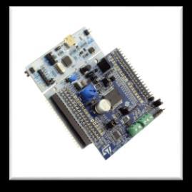
23 MC Connector Flexible MC Platform Full set of control board featuring all ST MCUs Full set of Power board featuring Power Transistor, IPM, MC Driver ICs. STM32XX-EVAL Control board STEVAL-XX Power board NUCLEO-XX Control board X-NUCLEO-IHM09M1 Connector Adapter +

24 Motor Control SDK Workflow 2/4 When the hardware is ready, if the user does not know the motor parameters, he can identify the motor. How? Using the Motor Profiler!!

25 Motor Profiler

26 ST MC Workbench Motor section contains: Motor parameters Motor sensor parameters Set Up Motor Parameters For a custom project, the user can set all the parameters.


27 Setup Motor Profiler Select Boards button and a list of supported boards will be shown. The Motor Profiler feature can be used only in the systems listed there.


28 Parameters set by the user: Setup Motor Profiler Motor pole pairs (Mandatory) Maximum application speed Not mandatory, if not selected, the Motor Profiler will try to reach the maximum allowed speed. Maximum Peak Current The maximum peak current delivered to the motor Expected bus voltage provided to the system. Selecting the kind of Motor Surface Permanent Magnet motor SM-PMSM or Internal Permanent Magnet motor I-PMSM In this last case is necessary to provide also the Ld/Lq ratio as input. SM-PMSM I-PMSM
29 Connect the HW chosen to the PC Click on the Connect button If the communication has succeed Click on the Profile button Setup Motor Profiler


30 Run Motor Profiler Procedure will end in about 60 seconds. Motor stopped Rs measurement Ls measurement Current regulators set-up Open loop Ke measurement Sensorless state observer set-up Switch over Closed loop Friction coefficient measurement Moment of inertia measurement Speed regulator set-up
31 Motor Profiler Complete At the end of the procedure, the measured parameters will be shown on a dedicated window. It is possible to import them on the workbench project and save them for later use.

32 Motor Identified: user can start and stop the motor thorough Start and Stop button. Motor Identified it is possible to create ST MC Workbench new project with the profiled motor,clicking New Project, in the Motor section the user can find
33 Motor Profiler The Motor Profiler algorithm is intended to be used for a fast evaluation of the ST three phase motor control solution (PMSM) Motor Profiler can be used only using compatible ST evaluation boards. Choosing the best ST HW according to the motor characteristics. The measurement precision can not be like when an instrumentation is used. Motor Profiler measurement cannot become significant for some motors, please see the limits reported in the software tool.
34 How To Manually Measure Motor Parameters


35 PMSM - Motor Parameters STMCWB Motor section contains: Electrical motor parameters Motor sensor parameters
36 PMSM - Electrical Motor Parameters Select either Internal PMSM or Surface Mounted PMSM according to the magnetic structure of your motor If you don t have this information you need to measure both Ld and Lq inductance for verifying it IF 2*(Lq-Ld)/(Ld+Lq) <15% SM-PMSM See next slides for learning how to measure motor inductances
37 PMSM Pole Pairs Number Usually, it s provided by motor supplier In case it s not or if you d like to double check it Connect a DC power supply between two (of the three) motor phases and provide up to 5% of the expected nominal DC bus voltage (you may also set current protection to nominal motor current) Rotate the motor with hands (you should notice some resistance) The number of rotor stable positions in one mechanical turn represents the number of pole pairs + - DC voltage source
38 How To Measure Motor Inductance 1/3 In case of SM-PMSM, the phase inductance does not depends on rotor position. In this case Ls notation is also utilized If you have a RLC meter Connect it phase-to-phase and measure series R and L at 100Hz (make sure rotor doesn t move) Repeat 4*number of pole pairs times: Turn the rotor by 360/(4*number of pole pairs) mechanical degrees, + - Wait for new measurements to get stable Read new measurement RLC meter f = 100Hz IF 2*(Lq-Ld)/(Ld+Lq) <15% SM - PMSM In this case, in the Workbench you can use for Rs and Ls half of the values read on the instrument STMCWB requires phase to neutral value with RLC meter
39 How To Measure Motor Inductance 1/3 IF 2*(max(L)-min(L))/(max(L)+min(L)) > 15% I - PMSM In the Workbench you can set Ld equal to minimum measured value divided by 2 (STMCWB requires phase to neutral value), set Lq equal to maximum measured value divided by 2 Set Rs equal to average measured resistance divided by two + - RLC meter f = 100Hz with RLC meter
40 How To Measure Motor Inductance 2/3 If you don t have a RLC meter For Rs, measure the DC stator resistance phase-to-phase and divide it by two Once measured Rs, it s necessary to measure L/R time constant between two motor phases. Connect DC voltage between two motor phases Connect oscilloscope Increase the voltage up to the value where the current equals the nominal one, rotor with align Don t move rotor any more Disable current protection of DC voltage source Unplug one terminal of the voltage source cable without switching it off Plug the voltage source rapidly and monitor on the scope the voltage and current waveform The measurement is good if the voltage is a nice step and the current increase like I * (1-e- t *L/R) Measure the time required to current waveform to rise up to 63% This time is Ld/Rs constant. Multiply it by Rs and you ll get Ld value I V V 0.63*I τ = L/R + - DC voltage source I without RLC meter
41 How To Measure Motor Inductance 3/3 Once measured Rs, it s necessary to measure Lq/Rs time constant between two motor phases. Connect DC voltage between two motor phases Connect oscilloscope Increase the voltage up to the value where the current equals the nominal one, rotor with align Lock the rotor in this position (so that it can not move anymore) Change DC voltage source connections as shown in the second figure Unplug one terminal of the voltage source cable without switching it off Plug the voltage source rapidly and monitor on the scope the voltage and current waveform The measurement is good if the voltage is a step and the current increase like I * (1-e - t *L/R ) Measure the time required to current waveform to rise up to 63% This time is Lq/Rs constant. Multiply it by 2Rs/3 and you ll get Lq value DC voltage source DC voltage source 0.63*I - V + V I τ = L/R + - I without RLC meter
42 How To Measure Bemf 1/2 The B-emf constant represents the proportionality constant between the mechanical motor speed and the amplitude of the B-emf induced into motor phases: To measure K e, usually is sufficient to turn the motor with your hands (or using drill or another motor mechanically coupled) and look with an oscilloscope to phase-to-phase induced voltage (V Bemf ) V Bemf = K e ω mec + - If you have no access to the rotor (e.g. in compressor applications) see next slide Measure VBemf frequency (FBemf) and peak-to-peak amplitude (VBemf A) Compute Ke in Vrms / Krpm: K e V Bemf A [ V peak to peak] pole pairs 2 2 F Bemf [ Hz] 60 number 1000 Access to rotor
 follow this procedure: Configure power stage (see later) + - Configure drive parameters for sensor-less as described in slides 16-19 but Set current ramp initial and final values")
43 How To Measure Bemf 2/2 If you have no access to rotor (e.g. in compressors) follow this procedure: Configure power stage (see later) + - Configure drive parameters for sensor-less as described in slides but Set current ramp initial and final values equal to motor nominal current value Set the speed ramp duration to 5000ms and speed ramp final value to around 50% of maximum application speed Set minimum start-up output speed higher than speed ramp final value Configure control stage Start the motor ramp-up and look with the oscilloscope to the voltage between two motor phases When the driving signal are switched off, rotor was probably moving then look to the B-emf K e V Bemf A [ V peak to peak] pole pairs 2 2 F Bemf [ Hz] 60 number 1000 No Access to rotor
 Motor rated current, must be provided by motor producer It will be used to limit the imposed motor phase current")
44 Other Electrical Parameters Max rated speed (rpm) Should be provided by motor producer (if not, set it to max application speed) Maximum motor rated speed above which motor can get damaged Maximum application speed must be lower than this value Nominal current (in A, 0-to-peak) Motor rated current, must be provided by motor producer It will be used to limit the imposed motor phase current during normal operation Nominal DC voltage Nominal DC bus voltage from which the motor should run, must be provided by motor producer Demagnetizing current Rotor demagnetizing current, may be provided by motor producer (if not use default value, i.e. motor nominal current) Used to limit the amount of target negative Id during flux weakening


45 Motor Control SDK Workflow 3/4 With Motor Profiler the motor is running but the user can develop his own code! Finalize the MC project using Workbench and use your favorite IDE to develop your code. MC Workbench

46 Create A New WB Project Based On The ST Evaluation Board Choose: New Project

47 Create A New WB Project Based On The ST Evaluation Board Choose: 1. Applications 1
48 Create A New WB Project Based On The ST Evaluation Board Choose: 2 2. Single or dual motor
49 Create A New WB Project Based On The ST Evaluation Board Choose: 3 3. Board approach: Choose if you are using Inverter, MC Kit or Power plus Control boards. Select the board used or create your own custom board.
50 Create A New WB Project Based On The ST Evaluation Board Choose: 4 4. Motor: Choose motor from a motor database. (You can save your motor parameters from your project.)

51 Create A New WB Project Based On An Example Choose the WB example project that best fits your needs. Choose the one with the same name of the ST evaluation board you are using, or choose the one with the same microcontroller you are using.

52 Create A New WB Project Starting from the board selection or example project, the control stage parameters will be populated with the correct values. For a custom project, the user can set all the parameters. STM32303E-EVAL

53 Set Up Power Stage Starting from the board selection or example project, the power stage parameters will be populated with the correct values. For a custom project, the user can set all the parameters.

54 Set Up Drive Parameters Starting from the board selection according to the chosen application, drive parameters will be populated with the correct values. For a custom project, the user can set all the parameters. Applications


55 Parameter Generation Once all the parameters have been entered in the ST MC Workbench, select the output path in the option form and choose SystemDriveParams present in the FW working folder. Click on the Generation button to configure the project.
. Select the correct user project from the drop-down menu according to the control stage used (e.g. STM32F10x_UserProject - STM3210B-EVAL). Compile and download.")
56 Compile And Program The MCU Run the IAR Embedded Workbench. Open the IAR workspace (located in Project\EWARM) folder according to the microcontroller family (e.g. STM32F10x_Workspace.eww for STM32F1). Select the correct user project from the drop-down menu according to the control stage used (e.g. STM32F10x_UserProject - STM3210B-EVAL). Compile and download. Compile & program Select project
. Select the proper user project from the drop-down menu according to the control stage used (e.g. STM3210B-EVAL). Compile and download.")
57 Compile And Program The MCU Optionally, run Keil uvision. Open the Keil workspace (located in Project\MDK-ARM) folder according to the microcontroller family (e.g. STM32F10x_Workspace.uvmpw for STM32F1). Select the proper user project from the drop-down menu according to the control stage used (e.g. STM3210B-EVAL). Compile and download. Program Compile Select project


58 Motor Control SDK Workflow 4/4 Finally the user can send commands (e.g. start, stop, execramp, ) via serial communication. Use the Workbench for debugging and real time communication.


59 Arrange the system for running the motor: Connect the control board with the power board using the MC cable. Connect the motor to the power board. Connect the power supply to the power board and turn on the bus. If the board is equipped with the LCD: Press joystick center on Fault Ack button to reset the faults. Press joystick right until the Speed controller page is reached. The press joystick down to reach the Start/Stop button. Press the center of the joystick to run the motor. Run The Motor
.")

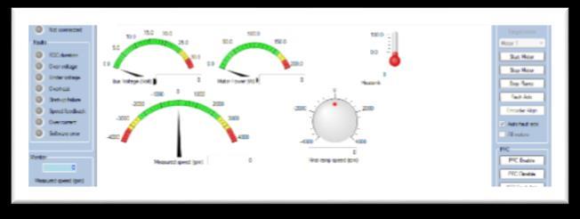
60 Optionally you can start the motor using the ST MC Workbench. Connect the PC to the control board with the USB to RS-232 dongle (and a null modem cable). Open the Workbench project used to configure the firmware and click on Monitor button. Select the COM port and click Connect button. This establish the communication with the firmware. To clear the fault, click Fault Ack and then Start Motor button to run the motor. Run The Motor Monitor Connect Select COM port Start Fault ACK

61 State Observer: Startup Procedure The sensorless algorithm is a bemf observer, so the motor should rotate to produce BEMF. That s why a startup procedure is required. Startup needs to be tuned (depend on inertia, load..) Two options of settings: basic and advanced Basic Advanced
62 How To Customize The Sensor-Less Start-Up Set current ramp initial and final values equal to motor nominal current value / 2 (if load is low at low speed, otherwise it can be set up to times nominal current value) Set speed ramp final value to around 30% of maximum application speed According to motor inertia it may be required to increase the speed ramp duration Set minimum start-up output speed to 15% of maximum application speed (if required, decreased it later) Set estimated speed band tolerance lower limit to 93.75% Enable the alignment at the beginning of your development (duration 2000ms, final current ramp value from 0.5 to 1 times motor nominal current according to load) Basic
63 Speed Current Startup Procedure: Basic, Acceleration Current ramp final value Current ramp initial value Current ramp duration time Speed ramp final value Speed ramp duration time
64 Speed Current Startup Procedure: Basic, Current Current ramp final value Current ramp initial value Current ramp duration time Speed ramp final value Speed ramp duration time

65 Speed Current Startup Procedure: Advanced The programmed rev-up sequence is composed by a number of stages; for each stage is possible to define the duration, the final torque reference and the final speed of the virtual sensor. It is possible to define the starting electrical angle. It is possible to set step variation in the current using duration zero. Torque ref. Stage 0 Duration Stage 0 time Final speed Stage 0 Stage 0 Stage 1 Stage 2 time
66 Troubleshooting Problem: SW error fault message appears and the motor do not even try to start Source: the FOC execution rate is too high and computation can not be ended in time Solution: In Drive settings, decrease ratio between PWM frequency and Torque and flux regulator execution rate (e.g. increasing Torque and flux regulator execution rate by one ) Problem: Over-current fault message appears and the motor do not even try to start 1 st possible source: wrong current sensing topology has been selected in power stage current sensing Solution: select right current sensing configuration 2 nd possible source: wrong current sensing parameters Solution: check power stage parameters 3 rd possible source: current regulation loop bandwidth is too high for this HW Solution: in drive parameters drive settings decrease current regulation bandwidth (normally down to 2000 rad/sec for 3shunt topology and 1000 rad/s for single shunt topology) Typical current regulation loop bandwidth max values are 4500 rad/sec for 1 shunt, 9000 rad/sec for 3-shunt
67 Troubleshooting Problem: Motor initially moves but then doesn t rev-up, then fault message Rev-up failure appears Source: typically this happens cause the current provided to the motor is not enough for making it accelerate so fast 1 st possible solution: decrease acceleration rate by increasing Start-up parameters speed ramp duration (being Start-up parameters speed ramp final value set to about 30% of maximum application speed) 2 nd possible solution: increase start-up current by increasing current ramp initial and final values up to motor nominal current Enabling Alignment phase (at least at the beginning of the development) makes start-up more deterministic, use around 2000ms, half of nominal current as first settings Problem: The rotor moves and accelerate following the ramp-up profile but then it stops and the fault message Rev-up failure appears (a mix of following problem sources can be occurring): 1 st possible source: Observer gain G2 is too high and this makes speed reconstruction a bit noisy (never recognized as reliable). A mix of following solutions could be required: 1 st possible solution: decrease observer gain G2 by successive steps: /2, /4, /6, /8 2 nd possible solution: Enlarge Drive parameters Speed/position feedback management variance threshold so as to make rotor locked check less demanding. (up to 80% for PLL and 400% for CORDIC) 2 nd possible source: the window where the reliability of the estimation is checked is too small 1 st possible solution: increase speed ramp final value to around 40% of maximum application speed 2 nd possible solution: decrease minimum start-up output speed to 10% of maximum application speed
68 Problem: The rotor moves and accelerate following the ramp-up profile but then it stops and the fault message Speed feedback appears Use speed ramps: having a target speed gently going from the start-up output speed to the final target will avoid abrupt variations of torque demand that could spoil B-emf estimation A mix of following problem sources can be occurring: 1 st possible source: Observer gain G2 is too high and this makes speed reconstruction a bit noisy (for the selected speed PI gains). A mix of following solutions could be required: 1 st possible solution: decrease observer gain G2 by successive steps: /2, /4, /6, /8 2 nd possible solution: Run motor in torque mode, if trouble doesn t exist in torque mode, it means speed regulator gains are not optimal try changing them 2 nd possible source: frequent situation when the start-up has been validated too early Troubleshooting Solution: Try increasing Start-up parameters consecutive successful start-up output test (normally to not more than 4-5) being minimum start-up output speed set to 15% of maximum application speed (if required, decreased it later) Problem: motor runs but current are not sinusoidal at all 1 st possible source: speed PI gains are not good Solution: decrease Kp gain (and act on Ki evaluating speed regulation over/under shooting during transients)


69 DAC functionality can help to debug and tune the application. Use DAC Channels Enabling Selection with WB Selection with LCD
 Green: phase A motor current Yellow: DAC ch1 (Obs. BEMF Alpha) Pink: DAC ch2 (Obs.")
70 Typical DAC waveforms of tuned system Use DAC Channels Green: phase A motor current Yellow: DAC ch1 (Ia) Pink: DAC ch2 (Ib) Green: phase A motor current Yellow: DAC ch1 (Obs. BEMF Alpha) Pink: DAC ch2 (Obs. BEMF Beta)

71 Thank You!
STM32 PMSM FOC SDK 4.2
 STM32 PMSM FOC SDK 4.2 Hands-on workshop with hardware tools Rev 1.5 Objectives 2 The purpose of this hands-on workshop is to: Get you up and running with the STM32 PMSM FOC SDK using the ST MC Workbench
ST Motor Profiler (STM32 PMSM FOC SDK) Tips and Tricks
 Tips and Tricks") ST Motor Profiler (STM32 PMSM FOC SDK) Tips and Tricks ST Motor Profiler 2 What is the Motor Profiler tool? The Motor Profiler tool is a new algorithm able to automatically measure the electrical characteristics
ST Motor Profiler (STM32 PMSM FOC SDK) Tips and Tricks ST Motor Profiler 2 What is the Motor Profiler tool? The Motor Profiler tool is a new algorithm able to automatically measure the electrical characteristics
General Purpose Permanent Magnet Motor Drive without Speed and Position Sensor
 General Purpose Permanent Magnet Motor Drive without Speed and Position Sensor Jun Kang, PhD Yaskawa Electric America, Inc. 1. Power consumption by electric motors Fig.1 Yaskawa V1000 Drive and a PM motor
TUTORIAL Motor Control Design Suite
 TUTORIAL Motor Control Design Suite April 2017 1 The Motor Control Design Suite provides a total solution for motor drive system design. From system specifications, the Motor Control Design Suite automatically
Modern Motor Control Applications and Trends Tomas Krecek, Ondrej Picha, Steffen Moehrer. Public Information
 Modern Motor Control Applications and Trends Tomas Krecek, Ondrej Picha, Steffen Moehrer Content Introduction Electric Machines Basic and Advance Control Techniques Power Inverters and Semiconductor Requirements
Freescale Semiconductor, I
 M68HC08 Microcontrollers 8-Bit Software Development Kit for Motor Control Targeting the MC68HC908MR32 SDKMR32UG/D Rev. 1, 11/2002 MOTOROLA.COM/SEMICONDUCTORS 8-Bit Software Development Kit for Motor Control
Welcome to ABB machinery drives training. This training module will introduce you to the ACS850-04, the ABB machinery drive module.
 Welcome to ABB machinery drives training. This training module will introduce you to the ACS850-04, the ABB machinery drive module. 1 Upon the completion of this module, you will be able to describe the
Permanent Magnet Synchronous Motor. High Efficiency Industrial Motors
 VoltPro is a new industrial motor range to meet high efficiency needs of industry by higher level of IE4 efficiency class. Main advantage of this product is cost effective solution ensured by using standard
InstaSPIN-FOC Training
 2013 Texas Instruments Motor Control Training Series -V th InstaSPIN-FOC Training Speed Sensorless Sensored FOC P Commanded Rotor Speed + Commanded i d = 0 + Commanded i q (torque) P + - + I P + + + V
CHAPTER 4 MODELING OF PERMANENT MAGNET SYNCHRONOUS GENERATOR BASED WIND ENERGY CONVERSION SYSTEM
 47 CHAPTER 4 MODELING OF PERMANENT MAGNET SYNCHRONOUS GENERATOR BASED WIND ENERGY CONVERSION SYSTEM 4.1 INTRODUCTION Wind energy has been the subject of much recent research and development. The only negative
Power Electronics & Drives [Simulink, Hardware-Open & Closed Loop]
![Power Electronics & Drives [Simulink, Hardware-Open & Closed Loop]](/thumbs/72/67745658.jpg "Power Electronics & Drives [Simulink, Hardware-Open & Closed Loop]") Power Electronics & [Simulink, Hardware-Open & Closed Loop] Project code Project theme Application ISTPOW801 Estimation of Stator Resistance in Direct Torque Control Synchronous Motor ISTPOW802 Open-Loop
Power Electronics & [Simulink, Hardware-Open & Closed Loop] Project code Project theme Application ISTPOW801 Estimation of Stator Resistance in Direct Torque Control Synchronous Motor ISTPOW802 Open-Loop
Quick Start Guide. Three-phase brushless DC motor driver expansion board based on L6230 for STM32 Nucleo (X-NUCLEO-IHM07M1)
") Quick Start Guide Three-phase brushless DC motor driver expansion board based on L6230 for STM32 Nucleo (X-NUCLEO-IHM07M1) Version 1.0 (September 18, 2015) Overview 2 1 Introduction to the STM32 Open Development
Quick Start Guide Three-phase brushless DC motor driver expansion board based on L6230 for STM32 Nucleo (X-NUCLEO-IHM07M1) Version 1.0 (September 18, 2015) Overview 2 1 Introduction to the STM32 Open Development
Quick Start Guide. Three-phase brushless DC motor driver expansion board based on L6230 for STM32 Nucleo (X-NUCLEO-IHM07M1)
") Quick Start Guide Three-phase brushless DC motor driver expansion board based on L6230 for STM32 Nucleo (X-NUCLEO-IHM07M1) Version 1.1.0 (May 16, 2016) Quick Start Guide Contents 2 X-NUCLEO-IHM07M1: Three-phase
Quick Start Guide Three-phase brushless DC motor driver expansion board based on L6230 for STM32 Nucleo (X-NUCLEO-IHM07M1) Version 1.1.0 (May 16, 2016) Quick Start Guide Contents 2 X-NUCLEO-IHM07M1: Three-phase
Solutions for Low Voltage and High Voltage Drives
 Solutions for Low Voltage and High Voltage Drives DC Motor Control Shield for Arduino & 750W Fan Demo with XMC1300, EiceDRIVER & IGBTs Electronica 2014, Munich Low & High Voltage Drives Markets & Example
1.1 Block Diagram of Drive Components of Electric Drive & their functions. Power Processor / Modulator. Control. Unit
 Introduction Motion control is required in large number of industrial and domestic applications like transportations, rolling mills, textile machines, fans, paper machines, pumps, washing machines, robots
G Prasad 1, Venkateswara Reddy M 2, Dr. P V N Prasad 3, Dr. G Tulasi Ram Das 4
 Speed control of Brushless DC motor with DSP controller using Matlab G Prasad 1, Venkateswara Reddy M 2, Dr. P V N Prasad 3, Dr. G Tulasi Ram Das 4 1 Department of Electrical and Electronics Engineering,
DeVi-Comfort B.V. Netherlands
 Vector Controller (FOC) for BLDC Motors Field-Oriented Control (FOC) is an important technology for motor systems, particularly those using permanent magnets (PM). In general, FOC provides an efficient
zub A Software Kernel for Servo Drives and Frequency Converters machine control AG
 A Software Kernel for Servo Drives and Frequency Converters zub machine control AG zub machine control AG Buzibachstrasse 31, CH-6023 Rothenburg, Switzerland Phone +41 41 54150-40 Fax +41 41 54150-49 info@zub.ch
Brushless dc motor (BLDC) BLDC motor control & drives
 BLDC motor control & drives") Brushless dc motor (BLDC) BLDC motor control & drives Asst. Prof. Dr. Mongkol Konghirun Department of Electrical Engineering King Mongkut s University of Technology Thonburi Contents Brushless dc (BLDC)
Brushless dc motor (BLDC) BLDC motor control & drives Asst. Prof. Dr. Mongkol Konghirun Department of Electrical Engineering King Mongkut s University of Technology Thonburi Contents Brushless dc (BLDC)
QUESTION BANK SPECIAL ELECTRICAL MACHINES
 SEVENTH SEMESTER EEE QUESTION BANK SPECIAL ELECTRICAL MACHINES TWO MARK QUESTIONS 1. What is a synchronous reluctance 2. What are the types of rotor in synchronous reluctance 3. Mention some applications
Question Bank ( ODD)
") Programme : B.E Question Bank (2016-2017ODD) Subject Semester / Branch : EE 6703 SPECIAL ELECTRICAL MACHINES : VII-EEE UNIT - 1 PART A 1. List the applications of synchronous reluctance motors. 2. Draw
Programme : B.E Question Bank (2016-2017ODD) Subject Semester / Branch : EE 6703 SPECIAL ELECTRICAL MACHINES : VII-EEE UNIT - 1 PART A 1. List the applications of synchronous reluctance motors. 2. Draw
CHAPTER 2 SELECTION OF MOTORS FOR ELECTRIC VEHICLE PROPULSION
 14 CHAPTER 2 SELECTION OF MOTORS FOR ELECTRIC VEHICLE PROPULSION 2.1 INTRODUCTION The selection of motors for electric vehicles is a major task. Since many literatures have been reported on various electric
EXPERIMENTAL VERIFICATION OF INDUCED VOLTAGE SELF- EXCITATION OF A SWITCHED RELUCTANCE GENERATOR
 EXPERIMENTAL VERIFICATION OF INDUCED VOLTAGE SELF- EXCITATION OF A SWITCHED RELUCTANCE GENERATOR Velimir Nedic Thomas A. Lipo Wisconsin Power Electronic Research Center University of Wisconsin Madison
APPLICATION NOTE
 12/18/02 Getting started using with a brushless motor Problem: For new users of an intelligent drive, starting to implement a motion control application can be a quite complex task. You need to know how
Sensorless Control Of Ac Motor Drives Speed And Position Sensorless Operation
 Sensorless Control Of Ac Motor Drives Speed And Position Sensorless Operation We have made it easy for you to find a PDF Ebooks without any digging. And by having access to our ebooks online or by storing
M o t o r C o n t r o l l e r s
 Motor Controllers Sensitron 221 West Industry Court Deer Park, NY 11729-4681 Phone (631) 586 7600 Fax (631) 242 9798 World Wide Web - www.sensitron.com E-mail - sales@sensitron.com 146-1109 Total Motion
3rd International Conference on Material, Mechanical and Manufacturing Engineering (IC3ME 2015)
") 3rd International Conference on Material, Mechanical and Manufacturing Engineering (IC3ME 2015) A High Dynamic Performance PMSM Sensorless Algorithm Based on Rotor Position Tracking Observer Tianmiao Wang
3rd International Conference on Material, Mechanical and Manufacturing Engineering (IC3ME 2015) A High Dynamic Performance PMSM Sensorless Algorithm Based on Rotor Position Tracking Observer Tianmiao Wang
AC Servodrives Bivector 300/500 Advanced solutions for automation
 AC Servodrives Bivector 300/500 Advanced solutions for automation ABB Automation Bivector Field Oriented Torque Control - optimal working point setting for maximum KT - robust control in flux weakening
A Robust Controller Design for a Brushless DC Drive System using Moving Average Speed Estimation on Cortex M3 ARM Microcontroller
 International Journal of Advanced Mechatronics and Robotics (IJAMR) Vol. 3, No. 1, January-June 2011; pp. 29-42; International Science Press, ISSN: 0975-6108 A Robust Controller Design for a Brushless
CENTROIDTM. AC Brushless Drive. Product Spec Sheet
 4 Axis, up to 2 KW motors Brake Output for each axis Overtemp and Overcurrent Protection All-software Configuration Self-cooled Fiber Optic Control CENTROIDTM AC Brushless Drive Product Spec Sheet AC Brushless
STSPIN Motor Drivers. Selection guide.
 STSPIN Motor Drivers Selection guide www.st.com/stspin ST, a pioneer in the field of motor and motion control, offers a wide selection of ICs to best match an application spectrum covering a wide range
ELECTRIC MACHINES EUROLAB 0.3 kw
 index SINGLE-PHASE MOTORS SPLIT-PHASE MOTOR DL 30130 CAPACITOR MOTOR DL 30140 UNIVERSAL MOTOR DL 30150 REPULSION MOTOR DL 30170 THREE PHASE ASYNCHRONOUS MOTORS SQUIRREL CAGE THREE PHASE ASYNCHRONOUS MOTOR
Technical Explanation for Inverters
 CSM_Inverter_TG_E_1_2 Introduction What Is an Inverter? An inverter controls the frequency of power supplied to an AC motor to control the rotation speed of the motor. Without an inverter, the AC motor
MANTECH ELECTRONICS. Stepper Motors. Basics on Stepper Motors I. STEPPER MOTOR SYSTEMS OVERVIEW 2. STEPPING MOTORS
 MANTECH ELECTRONICS Stepper Motors Basics on Stepper Motors I. STEPPER MOTOR SYSTEMS OVERVIEW 2. STEPPING MOTORS TYPES OF STEPPING MOTORS 1. VARIABLE RELUCTANCE 2. PERMANENT MAGNET 3. HYBRID MOTOR WINDINGS
High Voltage Solutions in HEV/EV Part II: - DC/DC Converters and Traction Inverters. Hong Huang
 High Voltage Solutions in HEV/EV Part II: - DC/DC Converters and Traction Inverters Hong Huang What will I get out of this session? Purpose: To provide an overview of complete high voltage power solutions
IJSRD - International Journal for Scientific Research & Development Vol. 4, Issue 01, 2016 ISSN (online):
:") IJSRD - International Journal for Scientific Research & Development Vol. 4, Issue 1, 216 ISSN (online): 2321-613 Close Loop Speed Response of BLDC Motor using Pi Controller Patel Milan V 1 Chaudhari Pooja
IJSRD - International Journal for Scientific Research & Development Vol. 4, Issue 1, 216 ISSN (online): 2321-613 Close Loop Speed Response of BLDC Motor using Pi Controller Patel Milan V 1 Chaudhari Pooja
Simulation of Indirect Field Oriented Control of Induction Machine in Hybrid Electrical Vehicle with MATLAB Simulink
 Simulation of Indirect Field Oriented Control of Induction Machine in Hybrid Electrical Vehicle with MATLAB Simulink Kohan Sal Lotf Abad S., Hew W. P. Department of Electrical Engineering, Faculty of Engineering,
BAC2000ind.
 DESCRIPTION ASI is a leader in the supply of industrial grade motor controllers with roots in electric vehicle technology dating back over 20 years. The is a high power density electric vehicle controller
ISSN: X Tikrit Journal of Engineering Sciences available online at:
 Taha Hussain/Tikrit Journal of Engineering Sciences 22(1) (2015)45-51 45 ISSN: 1813-162X Tikrit Journal of Engineering Sciences available online at: http://www.tj-es.com Analysis of Brushless DC Motor
Piktronik d. o. o. Cesta k Tamu 17 SI 2000 Maribor, Slovenia Fax:
 PIK tr nik Phone: +386-2-460-2250 Piktronik d. o. o. Cesta k Tamu 17 SI 2000 Maribor, Slovenia Fax: +386-2-460-2255 e-mail: info@piktronik.com www.piktronik.com Sensorless AC motor control for traction
Page 1. Design meeting 18/03/2008. By Mohamed KOUJILI
 Page 1 Design meeting 18/03/2008 By Mohamed KOUJILI I. INTRODUCTION II. III. IV. CONSTRUCTION AND OPERATING PRINCIPLE 1. Stator 2. Rotor 3. Hall sensor 4. Theory of operation TORQUE/SPEED CHARACTERISTICS
DHANALAKSHMI SRINIVASAN COLLEGE OF ENGINEERING AND TECHNOLOGY MAMALLAPURAM, CHENNAI
 DHANALAKSHMI SRINIVASAN COLLEGE OF ENGINEERING AND TECHNOLOGY MAMALLAPURAM, CHENNAI -603104 DEPARTMENT OF ELECTRICAL AND ELECTRONICS ENGINEERING QUESTION BANK VII SEMESTER EE6501-Power system Analysis
Using energy storage for modeling a stand-alone wind turbine system
 INTERNATIONAL JOURNAL OF ENERGY and ENVIRONMENT Volume, 27 Using energy storage for modeling a stand-alone wind turbine system Cornel Bit Abstract This paper presents the modeling in Matlab-Simulink of
VFD E Series. Features
 VFD E Series Output Frequency : 0.1 ~ 600 Hz. Built in PLC Function 500 Step program in Ladder Language. Side by side installation. Easy maintenance. Modular & Compact Design. Built-in MODBUS communication.
For motors controlled
 STEVE PETERSON Technical Training Engineer Yaskawa America Inc., Waukegan, IL Electronically reprinted from November 20, 2014 Choosing the right CONTROL METHOD for VFDs For motors controlled by a variable
A Practical Primer On Motor Drives (Part 11): AC And DC Motor Types
: AC And DC Motor Types") A Practical Primer On Motor Drives (Part 11): AC And DC Motor Types by Ken Johnson, Teledyne LeCroy, Chestnut Ridge, N.Y. ISSUE: December 2016 In the previous part in this series, the basic principles
A Practical Primer On Motor Drives (Part 11): AC And DC Motor Types by Ken Johnson, Teledyne LeCroy, Chestnut Ridge, N.Y. ISSUE: December 2016 In the previous part in this series, the basic principles
Development of Electric Scooter Driven by Sensorless Motor Using D-State-Observer
 Page 48 Development of Electric Scooter Driven by Sensorless Motor Using D-State-Observer Ichiro Aoshima 1, Masaaki Yoshikawa 1, Nobuhito Ohnuma 1, Shinji Shinnaka 2 Abstract This paper presents a newly
Note 8. Electric Actuators
 Note 8 Electric Actuators Department of Mechanical Engineering, University Of Saskatchewan, 57 Campus Drive, Saskatoon, SK S7N 5A9, Canada 1 1. Introduction In a typical closed-loop, or feedback, control
Inverter control of low speed Linear Induction Motors
 Inverter control of low speed Linear Induction Motors Stephen Colyer, Jeff Proverbs, Alan Foster Force Engineering Ltd, Old Station Close, Shepshed, UK Tel: +44(0)1509 506 025 Fax: +44(0)1509 505 433 e-mail:
Speed Control of Induction Motor using FOC Method
 RESEARCH ARTICLE OPEN ACCESS Speed Control of Induction Motor using FOC Method Hafeezul Haq*, Mehedi Hasan Imran**, H.Ibrahim Okumus***, Mohammad Habibullah**** *(Department of Electrical & Electronic
Whitepaper Dunkermotoren GmbH
 Whitepaper Dunkermotoren GmbH BG MOTORS WITH FIELD-ORIENTED CONTROL DR. BRUNO BASLER HEAD OF R&D PREDEVELOPMENT I DUNKERMOTOREN GMBH Dunkermotoren GmbH I Allmendstr. 11 I D-79848 Bonndorf I www.dunkermotoren.de
Delivering higher efficiency in motor drive applications
 Delivering higher efficiency in motor drive applications Simon Duggleby, Technical Marketing Manager, Electronics, RS Components Electric motors consume around half of all the electricity produced worldwide
A New Buck-Boost Converter for a Hybrid-Electric Drive Stand P. Mašek
 A New Buck-Boost Converter for a Hybrid-Electric Drive Stand P. Mašek This paper describes work on the laboratory working stand for a hybrid-electric drive located in laboratory T2:H1-26.The basic idea
Planning and Commissioning Guideline for NORD IE4 Synchronous Motors with NORD Frequency Inverters
 Getriebebau NORD GmbH & Co. KG Getriebebau-Nord-Straße 1 22941 Bargteheide, Germany www.nord.com Planning and Commissioning Guideline for NORD IE4 Synchronous Motors with NORD Frequency Inverters General
Devices Supported: KEB48220 KEB48221 KEB48300 KEB48301 KEB48400 KEB48401 KEB48600 KEB48601 KEB72330 EB KEB72450 KEB EB KEB72600 KEB
 Kelly KEB Brushless Motor Controller User s Manual Devices Supported: KEB48220 KEB48221 KEB48300 KEB48301 KEB48400 KEB48401 KEB48600 KEB48601 KEB72330 KEB EB72 72331 KEB72450 KEB EB72 72451 KEB72600 KEB
Design of Brushless Permanent-Magnet Machines. J.R. Hendershot Jr. T.J.E. Miller
 Design of Brushless Permanent-Magnet Machines J.R. Hendershot Jr. T.J.E. Miller Contents 1 GENERAL INTRODUCTION l 1.1 Definitions and types of brushless motor 1 1.2 Commutation,. 4 1.3 Operation of 3-phase
Brushed. Brushed. Brushed Motor
 Kelly Kelly Kelly Kelly KD KD KD KD Series Series Series Series DC DC DC DC Motor Motor Motor Motor Controller Controller Controller Controller User User User User s Manual Manual Manual Manual V 2.5 2.5
AC Induction Motor Controller with VCL
 Motor Controllers AC Induction Motor Controller with VCL www.curtisinstruments.com 1 The Ultimate Class III Truck Control System: Superb Performance and Value This new AC induction motor controller (inverter)
Código de rotor bloqueado Rotor bloqueado, Letra de código. Rotor bloqueado, Letra de código
 Letra de código Código de rotor bloqueado Rotor bloqueado, Letra de código kva / hp kva / hp A 0.00 3.15 L 9.00 10.00 B 3.15 3.55 M 10.00 11.00 C 3.55 4.00 N 11.00 12.50 D 4.00 4.50 P 12.50 14.00 E 4.50
Wind Turbine Emulation Experiment
 Wind Turbine Emulation Experiment Aim: Study of static and dynamic characteristics of wind turbine (WT) by emulating the wind turbine behavior by means of a separately-excited DC motor using LabVIEW and
Modeling and Simulation of BLDC Motor using MATLAB/SIMULINK Environment
 Modeling and Simulation of BLDC Motor using MATLAB/SIMULINK Environment SudhanshuMitra 1, R.SaidaNayak 2, Ravi Prakash 3 1 Electrical Engineering Department, Manit Bhopal, India 2 Electrical Engineering
Studies regarding the modeling of a wind turbine with energy storage
 Studies regarding the modeling of a wind turbine with energy storage GIRDU CONSTANTIN CRISTINEL School Inspectorate of County Gorj, Tg.Jiu, Meteor Street, nr. ROMANIA girdu23@yahoo.com Abstract: This paper
Standard Drives A & D SD Application Note
 SENSORLESS VECTOR CONTROL (SVC) Version A, 30.07.99 More detail of Vector Control principles are explained in DA64 Section 2. Some examples of SVC are given in Sections 4.2, 4.3 and 4.4. The MICROMASTER
Aspects of Permanent Magnet Machine Design
 Aspects of Permanent Magnet Machine Design Christine Ross February 7, 2011 Grainger Center for Electric Machinery and Electromechanics Outline Permanent Magnet (PM) Machine Fundamentals Motivation and
3242 G 024 BX4 CS/CC 24 3,6 18,2 77,3 1,6 / 12,4 9 / ball bearings, preloaded 0,015. stainless steel 370 electronically reversible
 Brushless DC-Servomotor with integrated Motion Controller and or CN interface 6 mnm For combination with Gearheads: 3/1, 32, 32/3, 32/3 S, 38/1, 38/1 S, 38/2, 38/2 S 3242... BX4 CS/CC 1 2 3 4 Nominal voltage
2232 S 024 BX4 CSD/CCD 24 12,4 6,4 67,7 2 / 17 4,1 / ball bearings, preloaded 0,015. stainless steel 77 electronically reversible
 NEW Brushless DC-Servomotor with integrated Motion Controller and or CN interface 18 mnm For combination with Gearheads: 22F, 22/7, 26 2232... BX4 CSD/CCD 1 2 3 4 Nominal voltage Terminal resistance, phase-phase
SP4 DOCUMENTATION. 1. SP4 Reference manual SP4 console.
 SP4 DOCUMENTATION 1. SP4 Reference manual.... 1 1.1. SP4 console... 1 1.2 Configuration... 3 1.3 SP4 I/O module.... 6 2. Dynamometer Installation... 7 2.1. Installation parts.... 8 2.2. Connectors and
COLLEGE OF ENGINEERING DEPARTMENT OF ELECTRICAL AND ELECTRONICS ENGINEERING QUESTION BANK SUBJECT CODE & NAME : EE 1001 SPECIAL ELECTRICAL MACHINES
 KINGS COLLEGE OF ENGINEERING DEPARTMENT OF ELECTRICAL AND ELECTRONICS ENGINEERING QUESTION BANK SUBJECT CODE & NAME : EE 1001 SPECIAL ELECTRICAL MACHINES YEAR / SEM : IV / VII UNIT I SYNCHRONOUS RELUCTANCE
Qingdao Zener Electric Co., Ltd
 Traction inverter, Power Supply, Emergency ventilation inverter for Light rail train Qingdao Zener Electric Co., Ltd Part 1 Power Supply for the Overhead Traction Line Introduction Conventional power supply
SINAMICS SM150. 4/2 Overview. 4/2 Benefits. 4/2 Design. 4/6 Function. 4/8 Selection and ordering data. 4/8 Options
 /2 Overview /2 Benefits /2 Design /6 Function /8 Selection and ordering data /8 Options Technical data /1 General technical data /15 Control properties /15 Ambient conditions /16 Installation conditions
Expanding Application of FRENIC-Lift Series for Elevators
 Expanding Application of FRENIC-Lift Series for Elevators Tetsuya Nomura Hiroyuki Yonezawa 1. Introduction In recent years the elevator industry has been transitioning from geared elevators that use standard
INSTITUTE OF AERONAUTICAL ENGINEERING Dundigal, Hyderabad
 INSTITUTE OF AERONAUTICAL ENGINEERING Dundigal, Hyderabad - 500 043 MECHANICAL ENGINEERING ASSIGNMENT Name : Electrical and Electronics Engineering Code : A40203 Class : II B. Tech I Semester Branch :
Quick Start Guide of CV50- ControlVIT Series
 ❶ Safety precautions Do not refit the inverter unauthorizedly; otherwise fire, electric shock or other injury may occur. Please install the inverter on fire-retardant material and keep the inverter away
Liquid cooled heavy duty converter
 Liquid cooled heavy duty converter FEATURES Extremely compact design -converter unit only 15 kg High enclosure class IP67 sealed from moisture and dust Liquid cooled with plain water or water/glycol mixture
PSIM Tutorial. HEV Design Suite. April
 PSIM Tutorial HEV Design Suite April 2013-1 - The HEV Design Suite provides a one-stop solution from system specifications to a completely designed HEV powertrain system. Using predefined templates, the
Prepared By: Ahmad Firdaus Bin Ahmad Zaidi
 Prepared By: Ahmad Firdaus Bin Ahmad Zaidi A stepper motor is an electromechanical device which converts electrical pulses into discrete mechanical rotational movements. Stepper motor mainly used when
CRANE FUNCTION MANUAL. FR-A (0.4K) to 04750(90K)-CRN FR-A (0.4K) to 06830(280K)-CRN FR-A (315K) to 12120(500K)-CRN
 to 04750(90K)-CRN FR-A (0.4K) to 06830(280K)-CRN FR-A (315K) to 12120(500K)-CRN") INVERTER CRANE FUNCTI MANUAL FR-A820-00046(0.4K) to 04750(90K)-CRN FR-A840-00023(0.4K) to 06830(280K)-CRN FR-A842-07700(315K) to 12120(500K)-CRN Crane Function The FR-A800-CRN has dedicated functions for
INVERTER CRANE FUNCTI MANUAL FR-A820-00046(0.4K) to 04750(90K)-CRN FR-A840-00023(0.4K) to 06830(280K)-CRN FR-A842-07700(315K) to 12120(500K)-CRN Crane Function The FR-A800-CRN has dedicated functions for
Kelly KDC Series/PM Motor Controller User s Manual
 Kelly KDC Series/PM Motor Controller User s Manual KDC48600 KDC48601 KDC48602 KDC48603 KDC72600 KDC72601 KDC72602 KDC72603 KDC72800 KDC72801 KDC72802 KDC72803 KDC12602 KDC12603 Rev.3.3 May 2011 Contents
8-bit. Application Note. Microcontrollers. AVR601: Atmel Modular Evaluation Kits for Motor Control Applications. 1.
 AVR601: Atmel Modular Evaluation Kits for Motor Control Applications 1. Introduction Following the success of the MC100 and MC200 motor control demonstration kits, Atmel is expanding the support for motor
Elbtalwerk GmbH. Universität Karlsruhe Elektrotechnisches Institut. Switched Reluctance Motor. Compact High-torque Electric Motor. Current.
 Elbtalwerk GmbH Switched Reluctance Motor Compact High-torque Electric Motor Current B1 Winding A1 D4 C1 C4 Pole D1 Rotation B4 A2 Rotor tooth Shaft A4 B2 Field line D3 C2 C3 D2 Stator A3 B3 Cooling air
URM-00 TRAINING MODULE FOR INDUSTRIAL ELECTRIC MOTORS FOR MAIN DRIVE AND CONTROL CIRCUITS EDUCATIONAL KIT TO STUDY MOTORS CONTROL AND PROTECTION
 URM-01/PP Stepper motor URM-02/CC DC motor (2-quadrant) URM-03/CA AC three-phase motor URM-04/BL Brushless motor URM-05/4Q DC motor (4-quadrant) URM-06/PS Speed and position DC motor URM-SMC Multifunzional
2
 Brushless DC motors 2 3 VFD VS ECM(PM Motors) Both take AC and convert to DC VFD is generally 3Ø ECM 1Ø in 3Ø out VFD & ECM Both have Rectifiers VFD & ECM both have transistor outputs VFD Out put
The use of Simulation in Electric Machine Design Stefan Holst, CD-adapco
 The use of Simulation in Electric Machine Design Stefan Holst, CD-adapco Motivation How often can a machine be started within an hour In Hybrids, what effect has the adjacent combustion drive train Space
International Journal of Advance Research in Engineering, Science & Technology
 Impact Factor (SJIF): 4.542 International Journal of Advance Research in Engineering, Science & Technology e-issn: 2393-9877, p-issn: 2394-2444 Volume 4, Issue 4, April-2017 Simulation and Analysis for
Experimental Validation of the Designed Topology
 Chapter 7 Experimental Validation of the Designed Topology 7.1 Introduction The position of permanent magnet Stepper motor is measured without using sensors, [58-60] but till now no references are available
Experiment 6: Induction
 Experiment 6: Induction Part 1. Faraday s Law. You will send a current which changes at a known rate through a solenoid. From this and the solenoid s dimensions you can determine the rate the flux through
Application Note 5283
 AEDB-9340 Series Commutation Encoder Module and Codewheel Alignment Techniques Application Note 5283 1000/1024/1250/2000/2048/2500 CPR Introduction The objective of this application is to provide a step
CHAPTER THREE DC MOTOR OVERVIEW AND MATHEMATICAL MODEL
 CHAPTER THREE DC MOTOR OVERVIEW AND MATHEMATICAL MODEL 3.1 Introduction Almost every mechanical movement that we see around us is accomplished by an electric motor. Electric machines are a means of converting
Unternehmensportrait. High Pole Servo. Stepper Motor basics vs. High Pole Servo
 High Pole Servo Stepper Motor basics vs High Pole Servo Stepper Motor types Hybrid-Stepper Motor Principal Construction like a BLDC (brushless DC Motor), but higher pole count Rotor and Stator silicon
SINAMICS GM150 IGCT version
 /2 Overview /2 Benefits /2 Design /6 Function /8 Selection and ordering data /8 Options Technical data /14 General technical data /15 Control properties /15 Ambient conditions /16 Installation conditions
ALM-Inline. Accurate Lambda Meter V1.1.2 COPY RIGHTS ECOTRONS LLC ALL RIGHTS RESERVED.
 ALM-Inline Accurate Lambda Meter V1.1.2 COPY RIGHTS ECOTRONS LLC ALL RIGHTS RESERVED Http://www.ecotrons.com Note: If you are not sure about any specific details, please contact us at info@ecotrons.com.
Planning and Commissioning Guideline for NORD IE4 Motors with NORD Frequency Inverters
 Planning and Commissioning Guideline for NORD IE4 Motors with NORD Frequency Inverters General Information From their basic function, motors with efficiency class IE4 are synchronous motors and are suitable
Synchronous Motor Drives
 UNIT V SYNCHRONOUS MOTOR DRIVES 5.1 Introduction Synchronous motor is an AC motor which rotates at synchronous speed at all loads. Construction of the stator of synchronous motor is similar to the stator
Remy HVH250 Application Manual Remy HVH250 Application Manual
 Preliminary Draft HVH250 MotorManual20110407.doc Page 1 of 31 TABLE OF CONTENTS 1. INTRODUCTION...3 2. SYSTEM OVERVIEW...3 2.1 Installation Overview...3 2.2 Motor Overview...3 3. HVH MOTOR TYPICAL APPLICATIONS...4
MOTOR CONTROLLER SPECIFICATION
 MOTOR CONTROLLER SPECIFICATION APACHE 120 / 240V 1. Scope This specification defines the basic characteristics for a motor controller Apache 120 / 240V, originally develop for laundry applications. This
Automotive Electric Drives An Overview
 Automotive Electric Drives An Overview Dr. Dorin ILES R&D Laboratory for Electric Drives ebm-papstst. Georgen Dr. Dorin ILES (iles@ieee.org) FISITA 2008 September 14-19, Munich, Germany Targets Overview
Kelly HSR Series Motor Controller with Regen User s Manual V 3.3. Kelly HSR Opto-Isolated Series Motor Controller with Regen.
 Kelly HSR Opto-Isolated Series Motor Controller with Regen User s Manual HSR72601 HSR72801 HSR12401 HSR12601 HSR12901 HSR14301 HSR14501 HSR14701 Rev.3.3 Dec. 2011 Contents Chapter 1 Introduction... 2 1.1
SME S.p.A. Via della Tecnica, n Arzignano (VI) - ITALY Phone:+39 (0444) Fax: +39 (0444)
 - ITALY Phone:+39 (0444) Fax: +39 (0444)") AC Induction Motor Controller DATASHEET (Rev. 1.4: April 2015) SME S.p.A. Via della Tecnica, n 40 36071 Arzignano (VI) - ITALY Phone:+39 (0444) 470511 Fax: +39 (0444) 451803 www.grupposme.com Model AC-M1
AC Induction Motor Controller DATASHEET (Rev. 1.4: April 2015) SME S.p.A. Via della Tecnica, n 40 36071 Arzignano (VI) - ITALY Phone:+39 (0444) 470511 Fax: +39 (0444) 451803 www.grupposme.com Model AC-M1
ELECTRICAL MACHINES LAB.
 ﺟﺎﻣﻌﺔ ﺟﺎزان ﻛﻠــﯿﺔ اﻟﮭﻨﺪﺳﺔ ﻗﺴــﻢ اﻟﮭﻨﺪﺳﺔ اﻟﻜﮭﺮﺑﺎﺋﯿﺔ Jazan University Engineering College Electrical Engineering Department ﻣﻌﻤﻞ اﻵﻻت اﻟﻜﮭﺮﺑﺎﺋﯿﺔ ELECTRICAL MACHINES LAB. ھﻨﺪﺳﺔ ﻛﮭﺮﺑﺎﺋﯿﺔ - 421 ھﻜﮫ : اﻟﻤﻘﺮر
ALTIVAR 58 AC Drives
 Class 8806 / 8839 / 8998 CONTENTS Schneider Electric Brands Page ALTIVAR 58 AC Drives............................................... 3 Drives Overview...................................................