SPOOL VALVE HYDRAULIC MOTORS
|
|
|
- Regina McLaughlin
- 5 years ago
- Views:
Transcription
1
2 SPOOL VALVE HYDRAULIC The operating principle of the motors is based on an internal gear design, consisting of a stator and rotor through which the output torque and speed are transmitted. The distributor valve is driven synchronously by the rotor through a cardan shaft ensuring that each one of the chambers of the motor are filled and emptied precisely. MM, MP, MR and MH motors have a Spool Valve. SPOOL VALVE -The distributor valve has been integrated with the output shaft. The valve has hydrodynamic bearings, and has infinite life when load ratings are not exceeded. GEAR SET - There are two forms of stator, hence and of gear set: MM and MP have plain teeth. These types motors are suitable for long operating periods at moderate pressures- or short operating periods at high pressures. MR and MH have teeth fitted with rollers. The rollers reduce local stress and the tangential reaction forces on the rotor reducing friction to a minimum. This gives long operating life and better efficiency even at continuous high pressures. Roller Gear Sets are recommended for operation with thin oil and for applications having continually reversing loads. Standard Motor The standard motor mounting flange is located as close to the output shaft as possible. This type of mounting supports the motor close to the shaft load. This mounting flange is also compatible with many standard gear boxes. Wheel Motor This type mounting flange makes the motor possible to fit a wheel hub or a winch drum so that the radial load acts midway between the two motor bearings. This gives the best utilization of the bearing capacity and is a very compact solution. Needle Bearing MP and MR have an output shaft supported in needle bearing. These types motors are suitable for absorbing static and dynamic radial loads. Low Leakage LL Series hydraulic motors have been designed to operate at the whole standard range of working conditions (pressure drop and frequency of rotation ), but with considerable decreased volumetric losses in the drainage ports. Their main purpose is to operate as series-connected motors in hydraulic systems. For this version is permissible decreasing of the maximal torque with up to 5% (at middle speed) and up to % (at high speed) in comparison to the standard versions of motors. Low Speed Valve LSV Series hydraulic motors have been designed to operate with normal pressure drop and to ensure -1 smooth run at low speed (up to min ), as the best security for operation is guaranteed at frequency -1 of rotation min. They have an increased starting pressure drop and are not recommended for using at pressure less than 40 bar. Free Running FR Series hydraulic motors have been designed to operate with high frequencies of rotation /over than min / and low pressure drop. These motors are produced with increased clearance at all friction parts. Additional advantages of FR version are prolonging of the life of the hydraulic motors at high frequencies of rotation, as well as the possibility to use them in systems with big variation of the loading. Volumetric efficiency can be affected.
3 HYDRAULIC MM APPLICATION»»»»» Conveyors Textile machines» Mining machinery Machine tools Ventilators Construction plant equipment and access platforms etc. CONTENTS Specification data... 5 Function diagrams Dimensions and mounting... 9 Shaft extensions... Permissible shaft loads... Order code GENERAL Displacement, [cm /rev.] Max. Speed, [RPM] Max. Torque, [danm] Max. Output, [kw] Max. Pressure Drop, [bar] Max. Oil Flow, [l/min] Min. Speed, [RPM] Pressure fluid O Temperature range, [C] 2 Optimal Viscosity range, [mm /s] Filtration OPTIONS» Model- Spool valve, gerotor» With or without flange» Side and rear ports» Series with pressure valve(s)» Shafts- straight and splined» Metric and BSPP ports» Speed sensoring; 8, ,1 4,5 1,8 2, Mineral based- HLP(DIN 51524) or HM(ISO 674/4) ISO code /16 (Min. recommended fluid filtration of 25 micron) MMP Series with Integrated Internal Crossover Relief Valve A B, p=0 bar ( bar) A MMP Series with Integrated Internal Crossover Relief Valve B A, p=0 bar ( bar) A B B P bar Pressure Losses MMD Series with Integrated Internal Crossover Relief Valves A B, p=0 bar ( bar) A Q, l/min B 4
4 MM SPECIFICATION DATA Type MM 8 MM 12,5 MM MM 2 MM 40 MM Displacement [cm /rev.] Max. Speed, [RPM] Max. Torque [danm] peak** Max. Output [kw] Max. Pressure Drop [bar] peak** Max. Oil Flow [l/min] Max. Inlet Pressure, [bar] cont Max. Return Pressure peak** 0-0 RPM w/o Drain Line or RPM Max. Pressure in RPM Drain Line, [bar] >800 RPM 0-max. RPM Max. Return Pressure with Drain Line [bar] peak** Max. Starting Pressure with Unloaded Shift, [bar] Min. Starting Torque [danm] at max. press. drop at max. press. drop Min. Speed***, [RPM] Weight, avg. [kg] MM MMF(S) MMFS MMP MMPF MMD MMDF 8, ,1 1,5 2,1 1,8 2, ,7 1,0 1,9 2, 2,7 2,5 2,7 2,6 2,8 12, ,6 2,, 2,4, ,2 1, ,4 2,8 2,6 2,8 2,7 2, ,5,5 5,1 2,4, ,1 2,9 0 2,1 2,5 2,9 2,7 2,9 2,8,0 1, ,7 6,4 2,4, ,4 4,8 0 2,2 2,6,0 2,8,0 2,9, ,1 5,7 6,6 1,8, , 4,6 25 2, 2,7,1 2,9,1,0, ,5 5,8 8 1,7 2, ,7 4,8 2,5 2,9,,1,,2,4 * Intermittent operation: the permissible values may occur for max. % of every minute. ** Peak load: the permissible values may occur for max. 1% of every minute. *** For speeds of 0 RPM or lower, consult factory or your regional manager. 1. Intermittent speed and intermittent pressure drop must not occur simultaneously. 2. Recommended filtration is per ISO cleanliness code /16. A nominal filtration of 25 micron or better.. Recommend using a premium quality, anti-wear type mineral based hydraulic oil HLP(DIN51524) or HM (ISO 674/4). If using synthetic fluids consult the factory for alternative seal materials Recommended minimum oil viscosity 1 mm²/s at operating temperature C. 5. Recommended maximum system operating temperature is 82ºC. 6. To assure optimum motor life fill with fluid prior to loading and run at moderate load and speed for 15-0 min. 5
5 MM Motoren FUNCTION DIAGRAMS MM 8 MM 12,5 The function diagrams data was collected at back pressure 5 bar and oil with viscosity of 2 mm²/s at C. 6
6 MM FUNCTION DIAGRAMS MM MM 2 The function diagrams data was collected at back pressure 5 bar and oil with viscosity of 2 mm²/s at C. 7
7 MM FUNCTION DIAGRAMS MM 40 MM The function diagrams data was collected at back pressure 5 bar and oil with viscosity of 2 mm²/s at C. 8
8 MM DIMENSIONS AND MOUNTING DATA max L Port A Porting Rear Ports Port B Mounting Port A Three Bolts Mount Port B 5,4±0,1 S -SidePorts max L 45±0,2 Port A Port B 11,7±0, F - Oval Mount (2 Holes) P -SidePortswith Single Crossover Relief Valve max L Port A Port B 21,2±0,15 D -SidePortswith Dual Crossover Relief Valve max L C P T (A, B) : xm6-12 mm depth :2xG/8or(M18x1,5)-12mmdepth :G1/8or(Mx1)-mmdepth Port A Port B Standard Rotation Viewed from Shaft End Port A Pressurized - CW Port B Pressurized - CCW Reverse Rotation Viewed from Shaft End Port A Pressurized - CCW Port B Pressurized - CW 40,±0, Type MM 8 MM12,5 MM MM 2 MM 40 MM L,mm ,5 121,5 Type MMS 8 MMS12,5 MMS MMS 2 MMS 40 MMS L,mm ,5 122,5 Type MMP 8 MMP12,5 MMP MMP 2 MMP 40 MMP L,mm ,5 12,5 Type MMD 8 MMD12,5 MMD MMD 2 MMD 40 MMD L,mm ,5 151,5 L,mm 1,5 5,5 8,5 1,
9 MM SHAFT EXTENSIONS C - ø16 straight, Parallel key 5x5x16 DIN 6885 Max. Torque,9 danm 0,4 CK - ø14 Straight, Parallel key 5x5x16 DIN 6885 Max. Torque danm -0,018 0,4 * M6 min 11 Deep * M6 min 11 Deep SH - ø16,5 Splined, B17x14 DIN 5482 Max. Torque 4,4 danm 0,4 * M6 min 11 Deep - Motor Mounting Surface * For F Mounting PERMISSIBLE SHAFT LOAD P a max =80 dan P =1 dan rad The permissible radial shaft load [Prad] is calculated from the distance [L] between the point of load application and the mounting surface: P = rad 0 n X 1040 (61,5+L), [dan] P rad dan The drawing shows the permissible radial load when L= mm. If the calculated shaft load exceeds the permissible, a flexible coupling must be used.
10 MM MM ORDER CODE Pos.1 - Adjustment Option omit - without valve P -Side ports with single crossover relief valve D -Side ports with dual crossover relief valve Pos.2 - Mounting Flange omit - Three bolts mount F -Oval mount, two holes Pos. - Port type (not valid for P and D version) omit - Rear ports S - Side ports Pos.4 - Displacement code 8-8,2 [cm /rev] 12,5-12,9 [cm /rev] ,0[cm /rev] - 1,8[cm /rev] - 40,0[cm /rev] -,0[cm /rev] Pos. 6 - Ports omit - BSPP (ISO 228) M - Metric (ISO 262) Pos. 7 - Line to controled ** (see page 4) /L - B A (left running) /R - A B (right running) Pos. 8 - Valve Rated Pressure *** / /0 - p= bar - p=0 bar Pos. 9 - Special Features (see page 46) Pos. - Design Series omit - Factory specified Pos. 5 - Shaft Extensions* C - ø16 straight, Parallel key 5x5x16 DIN 6885 VC - ø16 straight, Parallel key 5x5x16 DIN 6885 with corrosion resistant bushing CK - ø14 straight, Parallel key 5x5x16 DIN 6885 SH - ø16,5 splined, B17x14 DIN 5482 NOTES: * The permissible output torque for shafts must not be exceeded! ** For P option useful only. *** For P and D option useful only. The hydraulic motors are mangano-phosphatized as standard. F - FLANGE KIT (2 Holes) Order No: Flange Kit includes screws - M6x14 for attaching flange to the motor. 11
11 HYDRAULIC MP APPLICATION» Conveyors» Feeding mechanism of robots and manipulators» Metal working machines» Textile machines» Machines for agriculture» Food industries» Grass cutting machinery etc. CONTENTS Specification data Function diagrams Dimensions and mounting Wheel motor... 2 Shaft extensions Permissible shaft loads Permissible shaft Seal Pressure Order code OPTIONS» Model- Spool valve, gerotor» Flange and wheel mount» Motor with needle bearing» Side and rear ports» Shafts- straight, splined and tapered» Shaft seal for high and low pressure» Metric and BSPP ports» Speed sensoring» Other special features GENERAL Displacement, [cm /rev.] Max. Speed, [RPM] Max. Torque, [danm] Max. Output, [kw] Max. Pressure Drop, [bar] Max. Oil Flow, [l/min] Min. Speed, [RPM] Pressure fluid O Temperature range, [C] 2 Optimal Viscosity range, [mm /s] Filtration 25 62, ,,, Mineral based- HLP(DIN 51524) or HM(ISO 674/4) ISO code /16 (Min. recommended fluid filtration of 25 micron) Pressure drop (bar) 0 Oil flow in drain line Viscosity 2 (mm /s) 5 5 Oil flow in drain line (l/min) 2,5 1,8,5 2,8 Pressure Losses p bar Q l/min 12
12 MP SPECIFICATION DATA Specification Data for MP... motors with C, CO, SH, K and SA shafts. (ø28,56 sealing diameter) Type Displacement, [cm /rev.] Max. Speed, [RPM] Max. Torque [danm] peak** Max. Output, [kw] Max. Pressure Drop [bar] peak** Max. Oil Flow [l/min] Max. Inlet Pressure [bar] peak** Max. Return Pressure with Drain Line [bar] peak** Max. Starting Pressure with Unloaded Shaft, [bar] at max. press. Min. Starting Torque drop [danm] at max. press. drop Min. Speed***, [RPM] Weight, avg. [kg] MP(F) MPQ(N) MP(F)(N)E MPW(N) MPQ(N)E MP ,5 79, , 4,7 6,7 4,5 6, ,2 5,6 5,0 6,1 5, 5,5 4, 6,1 8,6 5,8 7, ,6 15 5,6 5,0 6,1 5, 5,5 6,2 8,2,7 8,4 11, ,4 6,9 5,7 5,1 6,2 5,4 5,6 9,4 11,9 14,,1 12,2 7,8 5,8 5,2 6, 5,5 5,7 15,1 19,5 22,4,2 12,5 1,2 16,8 5,9 5, 6,4 5,6 5, ,8 158, ,516, , 2,7 27,5,5 12,8 16,6 21 6,1 5,5 6,6 5,8 6, ,7 29,8 6,5 12 9,7 26,6 6,2 5,6 6,7 5,9 6, , 7,8 4,8,1 12,1 8 28,2 5,5 6,4 5,8 6,9 6,1 6, ,6 45, ,5 42,6 6,6 6,0 7,1 6, 6, , 68,5 7, ,6 54,2 6,8 6,2 7, 6,5 6, , ,4 61,9 7,1 6,5 7,6 6,8 7, ,4 4,6 7, ,5,8 7,6 6,8 8,1 7,2 7, , ,5, 7,2 5, , ,9 9,5 8, 9,0 9, 8,6 9,2 8,8 8,5 * Intermittent operation: the permissible values may occur for max. % of every minute. ** Peak load: the permissible values may occur for max. 1% of every minute. *** For speeds of RPM or lower, consult factory or your regional manager. 1. Intermittent speed and intermittent pressure drop must not occur simultaneously. 2. Recommended filtration is per ISO cleanliness code /16. A nominal filtration of 25 micron or better.. Recommended using a premium quality, anti-wear type mineral based hydraulic oil HLP(DIN51524) or HM (ISO 674/4). If using synthetic fluids consult the factory for alternative seal materials. 4. Recommended minimum oil viscosity 1 mm²/s at operating temperatures Recommended maximum system operating temperature is 82 C. 6. To assure optimum motor life fill with fluid prior to loading and run at moderate load and speed for -15 minutes. 1
13 MP SPECIFICATION DATA (continued) Specification Data for MP... motors with CB, KB, OB and HB shafts. (ø5 sealing diameter) Type Displacement, [cm /rev.] Max. Speed, [RPM] Max. Torque [danm] peak** Max. Output, [kw] Max. Pressure Drop [bar] peak** Max. Oil Flow [l/min] Max. Inlet Pressure [bar] peak** Max. Return Pressure with Drain Line [bar] peak** Max. Starting Pressure with Unloaded Shaft, [bar] at max. press. Min. Starting Torque drop [danm] at max. press. drop Min. Speed***, [RPM] Weight, avg. [kg] MP(F)... B MP(F)E...B MP ,5 79, , 4,7 6,7 4,5 6, ,2 5,6 6,1 4, 6,1 8,6 5,8 7, ,6 15 5,6 6,1 6,2 8,2,7 8,4 11, ,4 6,9 5,7 6,2 9,4 11,9 14,,1 12,2 7,8 5,9 6,4 15,1 19,5 22,4,2 12,5 1,2 16,8 6 6, ,8 158, ,516, , 2,7 27,5,5 12,8 16,6 21 6,2 6, ,7 29,8 6,5 12 9,7 26,6 6, 6, , 7,8 4,8,1 12,1 8 28,2 5,5 6,5 6, ,6 45,6 55 9,5 12,5 7,5 42,6 6,7 7, , 68,5 9, ,8 54,2 6,9 7, , , ,8 61,9 7,2 7, ,4 6,2 7, ,8,8 7,7 8, , ,5, 7,2 5, , ,6 9,4,1 * Intermittent operation: the permissible values may occur for max. % of every minute. ** Peak load: the permissible values may occur for max. 1% of every minute. *** For speeds of RPM or lower, consult factory or your regional manager. 1. Intermittent speed and intermittent pressure drop must not occur simultaneously. 2. Recommended filtration is per ISO cleanliness code /16. A nominal filtration of 25 micron or better.. Recommended using a premium quality, anti-wear type mineral based hydraulic oil HLP(DIN51524) or HM (ISO 674/4). If using synthetic fluids consult the factory for alternative seal materials. 4. Recommended minimum oil viscosity 1 mm²/s at operating temperatures Recommended maximum system operating temperature is 82 C. 6. To assure optimum motor life fill with fluid prior to loading and run at moderate load and speed for -15 minutes. 14
14 MP MP 25 FUNCTION DIAGRAMS MP 2 The function diagrams data was collected at back pressure 5 bar and oil with viscosity of 2 mm²/s at C. 15
15 MP MP 40 FUNCTION DIAGRAMS MP The function diagrams data was collected at back pressure 5 bar and oil with viscosity of 2 mm²/s at C. 16
16 MP FUNCTION DIAGRAMS MP 80 MP 0 The function diagrams data was collected at back pressure 5 bar and oil with viscosity of 2 mm²/s at C. 17
17 MP FUNCTION DIAGRAMS MP 125 MP 1 The function diagrams data was collected at back pressure 5 bar and oil with viscosity of 2 mm²/s at C. 18
18 MP MP FUNCTION DIAGRAMS MP 2 The function diagrams data was collected at back pressure 5 bar and oil with viscosity of 2 mm²/s at C. 19
19 MPM Motoren FUNCTION DIAGRAM MP 15 MP 400 The function diagram data was collected at back pressure 5 bar and oil with viscosity of 2 mm²/s at C.
20 MP FUNCTION DIAGRAM MP 0 M danm 75 Q=5 l/min l/min 0 l/min 40 l/min l/min l/min l/min 75 l/min l/min int. 2kW kw 4kW % 5kW 6kW 65% % % 1 bar 90 bar 75 bar N=0,5kW 1kW 80% 75% int. min bar 45 bar 0 bar 15 bar n -1 (rpm) MP M danm Q=5 l/min l/min 0 l/min 40 l/min l/min l/min l/min 75 l/min l/min int. 2kW kw 4kW 5kW 80 bar bar N=0,5kW 1kW 80% 75% % 65% % % 55 bar 45 bar 0 bar 5 15 bar int. min -1 n (rpm) The function diagram data was collected at back pressure 5 bar and oil with viscosity of 2 mm²/s at C. 21
21 MP DIMENSIONS AND MOUNTING DATA max L Port A Porting Side Ports Port B 55±0,1 Mounting Oval Mount (2 Holes) 2xø1,5 +0,4 6,4±0,2 E -RearPorts Port B F - Oval Mount (4 Holes) 4xø1,5 +0,4 ø6,4±0,2 Port A 55±0,1 C : 4xM8-1mmdepth P (A, B) : 2xG1/2 or 2xM22x1,5-15 mm depth T : G1/4 or M14x1,5-12 mm depth (plugged) 55±0,1 Q - Square Mount (4 Bolts) min 15 deep Standard Rotation Viewed from Shaft End Port A Pressurized - CW Port B Pressurized - CCW Reverse Rotation Viewed from Shaft End Port A Pressurized - CCW Port B Pressurized - CW Type MP(F) 25 MP(F) 2 MP(F) 40 MP(F) MP(F) 80 MP(F) 0 MP(F) 125 MP(F) 1 MP(F) MP(F) 2 MP(F) 15 MP(F) 400 MP(F) 0 MP(F) L, mm Type L, mm Type L, mm Type L, mm L, mm 1,2 MPQ 25 19,4 MP(F)E ,2 MPQE ,4 5, 14,5 MPQ 2,7 MP(F)E 2 152,5 MPQE 2 158,7 6,0 15,2 MPQ ,4 MP(F)E 40 15,2 MPQE ,4 7,40 15,6 MPQ 141,8 MP(F)E 155,8 MPQE 162,0 6,67 19,6 MPQ ,8 MP(F)E ,8 MPQE ,0,67 142,2 MPQ 0 148,4 MP(F)E 0 162,4 MPQE 0 168,6 1, 145,6 MPQ ,8 MP(F)E ,8 MPQE ,0 16,67 1,2 MPQ 1 156,4 MP(F)E 1 1,4 MPQE 1 176,6 21, 155,6 MPQ 161,8 MP(F)E,8 MPQE 182,0 26,67 162,2 MPQ 2 168,4 MP(F)E 2 182,4 MPQE 2 188,6, 171,6 MPQ ,8 MP(F)E ,8 MPQE ,0 42,67 182,2 MPQ ,4 MP(F)E 400 2,4 MPQE 400 8,6 5, 19,0 MPQ 0 199,0 MP(F)E 0 21,0 MPQE 0 219,0 66,6 2,5 MPQ 216,5 MP(F)E,5 MPQE 26,5 84,
22 MP DIMENSIONS AND MOUNTING DATA - MPW W - Wheel Mount max L min 55±0,1 max 5 P (A,B) Port A Port B T Type MPW(N) 25 MPW(N) 2 MPW(N) 40 MPW(N) MPW(N) 80 MPW(N) 0 MPW(N) 125 MPW(N) 1 MPW(N) MPW(N) 2 MPW(N) 15 MPW(N) 400 MPW(N) 0 MPW(N) L, mm L 1, mm 77,0 5,2 78,0 6, 79,5 7,4 78,5 6,67 82,5,67 85,0 1, 88,5 16,67 9,0 21, 98,5 26,67 5,0, 114,5 42,67 125,0 5, 18,5 66,6 156,0 84,0 max 0 Standard Rotation Viewed from Shaft End Port A Pressurized - CW Port B Pressurized - CCW Reverse Rotation Viewed from Shaft End Port A Pressurized - CCW Port B Pressurized - CW P (A, B) : 2xG1/2 or 2xM22x1,5-15 mm depth T : G1/4 or M14x1,5-12 mm depth (plugged) ø±0,1 PERMISSIBLE SHAFT LOADS MPWN MPW The curves apply to a B bearing life of 0 hours. 1: Max. radial shaft load -1 2: n= min P -1 rad : n= min dan -1 4: n=800 min 10 Prad dan 10 1: Max. radial shaft load -1 2: n=00 min -1 : n=0 min -1 4: n=800 min ,4 mm ,4 mm Pa max =1 dan Pa max =1 dan Pa max = dan Pa max = dan 2
23 MP+MR SHAFT EXTENSIONS FOR MP AND MR C - ø25 straight, Parallel key A8x7x2 DIN 6885 Max. Torque 4 danm CB - ø2 straight, Parallel key Ax8x45 DIN 6885 Max. Torque 77 danm M8 min16 Deep 4,2±0,5 M8 min16 Deep 56,5 +0,4-1,0 max 49* CO - ø1" straight, Parallel key ¼"x¼"x1¼" BS46 Max. Torque 4 danm SB - splined A25x22xH DIN 5482 Max. Torque 4 danm ø25±0,2 ø22±0,10 M8 min16 Deep 4,2±0,5 max 49* SH - splined, BS 59 (SAE 6B) Max. Torque 40 danm M8 min16 Deep max 49* ø25,2±0,0 KB - tapered 1:, Parallel key B6x6x DIN 6885 Max. Torque 77 danm 6±0,7 58±0,4 ø4,5±0,1 S=41 Tightening Torque ±1 danm ø5±0,01 min 26,4 4,2±0,5 5±0,25 K - tapered 1:, Parallel key B5x5x14 DIN 6885 Max. Torque 40 danm OB - tapered 1:8 SAEJ 1, Parallel key 5 "x "x1¼" BS46 Max. Torque 77 danm max 49* ø4,5±0,1 S=0 Tightening Torque ±1 danm 56,5 +0,4-1,0 5±0,6 ø4 S=1 7/ 16 " Tightening Torque ±1 danm ø28,56±0,01 5±0,25 5±0,25 SA - splined, B25x22h9 DIN 5482 Max. Torque 40 danm M8 min16 Deep max 49* HB -ø1¼" splined 14T, ANSI B Norm Max. Torque 77 danm 4,2±0,5 M8 min16 Deep 56,5 +0,4-1,0 - Motor Mounting Surface * - For Q-flange 24
24 MP+MR PERMISSIBLE SHAFT LOADS FOR MP AND MR The permissible radial shaft load P to the mounting flange. rad depends on the speed (RPM) and distance (L) from the point of load Mounting Flange cylindrical - C, CO Shaft Version tapered-k,splined-sh Radial Shaft Load P rad * 800 x 200, dan n 95+L -1 n< min ; max P rad=800 dan -1 *n> _ min ; L<55 mm splined - HB cylindrical - CB 800 n x L, dan cylindrical - C, CO 800 n x L, dan The curves apply to a B bearing life of 0 hours. Prad dan 10 0 MPN and MRN 1: Max. radial shaft load -1 2: n= min -1 : n= min -1 4: n=800 min MP and MR Radial Shaft Load Prad for C, CO Shaft Extensions by L=0 (24) mm P rad Oval Mount Pa Pa max max =1 dan = dan mm Square Mount P rad dan Pa max =1 dan Pa max = dan 25
25 MP+MR MAX. PERMISSIBLE SHAFT SEAL PRESSURE FOR MP AND MR MP/MR...U1 motors with high pressure seal and without drain connection: The shaft seal pressure equals the average of input pressure and return pressure. MP/MR...U motors with high pressure seal and drain connection: The shaft seal pressure equals the pressure in the drain line. P = P input +P seal 2 return MP/MR...1 motors with low pressure seal or standard shaft seal and without drain connection: The shaft seal pressure never exceeds the pressure in the return line. MP/MR... motors with low pressure seal or standard shaft seal and with drain connection: The shaft seal pressure equals the pressure in the drain line. P bar 4 Max. return pressure without drain line or max. pressure in the drain line : Drawing for Low Pressure Seal 2: Drawing for Standard Shaft Seal for "...B" shafts : Drawing for Standard Shaft Seal (" D" Seal) 4: Drawing for High Pressure Seal (" U" Seal) n, min -1 26
26 MP ORDER CODE MP Pos.1 - Mounting Flange omit - Oval mount, two holes F - Oval mount, four holes Q -Square mount, four bolts W - Wheel mount Pos.2 - Option (needle bearings) omit - none N - with needle bearings Pos. - Port type omit - Side ports E - Rear ports Pos.4 - Displacement code 25* - 25,0 [cm /rev] 2* - 2,0 [cm /rev] 40* - 40,0 [cm /rev] - 49,5 [cm /rev] 80-79,2 [cm /rev] 0-99,0 [cm /rev] ,8 [cm /rev] 1-158,4 [cm /rev] - 198,0 [cm /rev] 2-247,5 [cm /rev] 15-16,8 [cm /rev] ,0 [cm /rev] 0-495,0 [cm /rev] - 62,6 [cm /rev] Pos.5 - Shaft Extensions**(see page 24) C - ø25 straight, Parallel key A8x7x2 DIN6885 VC - ø25 straight, Parallel key A8x7x2 DIN6885 with corrosion resistant bushing ø1" straight, Parallel key ¼"x¼"x1¼" BS46 CO VCO SH VSH K SA VSA CB KB SB OB HB - - ø1" straight, Parallel key ¼"x¼"x1¼" BS46 with corrosion resistant bushing - ø25,2 splined BS 59 (SAE 6B) - ø25,2 splined BS 59 (SAE 6B) with corrosion resistant bushing - ø28,56 tapered 1:, Parallel key B5x5x14 DIN ø24,5 splined B 25x22 DIN ø24,5 splined B 25x22 DIN 5482 with corrosion resistant bushing - ø2 straight, Parallel key Ax8x45 DIN ø5 tapered 1:, Parallel key B6x6x DIN splined A 25x22 DIN ø1¼" tapered1:8, Parallel key "x "x1¼" BS46 - ø1¼" splined 14T ANSI B Pos. 6 - Shaft Seal Version (see page 26) omit - Low pressure shaft seal or Standard shaft seal for...b shaft D - Standard shaft seal U - High pressure shaft seal (without check valves) Pos. 7 - Drain Port omit - with drain port 1 - without drain port Pos. 8 - Ports omit - BSPP (ISO 228) M - Metric (ISO 262) Pos. 9 - Special Features (see page 46) Pos. - Design Series omit - Factory specified * Not with Low Pressure Seal ** The permissible output torque for shafts must not be exceeded! NOTES: The following combinations are not allowed: - Q flange with...b shafts; - W flange with...b shafts, U option or E rear ports; - N option with...b shafts, Low Pressure Seal or U option; -...B shafts with D and U shaft seals. The hydraulic motors are mangano-phosphatized as standard. 27
27 HYDRAULIC MR APPLICATION» Conveyors» Feeding mechanism of robots and manipulators» Metal working machines» Textile machines» Machines for agriculture» Food industries» Grass cutting machinery etc. CONTENTS Specification data Function diagrams Dimensions and mounting... 6 Shaft extensions Permissible shaft loads Permissible shaft Seal Pressure Order code... 7 GENERAL Displacement, [cm /rev.] Max. Speed, [RPM] Max. Torque, [danm] Max. Output, [kw] Max. Pressure Drop, [bar] Max. Oil Flow, [l/min] Min. Speed, [RPM] Pressure fluid O Temperature range, [C] 2 Optimal Viscosity range, [mm /s] Filtration OPTIONS» Model- Spool valve, roll-gerotor» Flange mount» Motor with needle bearing» Side and rear ports» Shafts- straight, splined and tapered» Shaft seal for high and low pressure» Metric and BSPP ports» Speed sensoring» Other special features 51, , Mineral based- HLP(DIN 51524) or HM(ISO 674/4) ISO code /16 (Min. recommended fluid filtration of 25 micron) Oil flow in drain line P bar Pressure Losses 0 Pressure drop (bar) 0 Viscosity 2 (mm /s) 5 5 Oil flow in drain line (l/min) 2,5 1,8,5 2, Q, l/min 28
28 MR SPECIFICATION DATA Specification Data for MR... motors with C, CO, SH, K and SA shafts. (ø28,56 sealing diameter) Type Displacement, [cm /rev.] Max. Speed, [RPM] Max. Torque [danm] peak** Max. Output, [kw] Max. Pressure Drop [bar] peak** Max. Oil Flow [l/min] Max. Inlet Pressure [bar] peak** Max. Return Pressure with Drain Line [bar] peak** Max. Starting Pressure with Unloaded Shaft, [bar] Min. Starting Torque [danm] Min. Speed***, [RPM] Weight, avg. [kg] MR(F) For rear ports: MRQ(N) +0,6 kg at max. press. drop at max. press. drop MR , , ,8 6,2 80, , ,9 6, 99, ,2 6,6 125, ,5 14, , 6,8 159, , ,5 7,0 199, , ,2 2, , ,4 7,8 15, ,5 9,1 8, ,8 6, ,5 9,8 9, * Intermittent operation: the permissible values may occur for max. % of every minute. ** Peak load: the permissible values may occur for max. 1% for every minute. *** For speeds of RPM or lower, consult factory or your regional manager. 1. Intermittent speed and intermittent pressure drop must not occur simultaneously! 2. Recommended filtration is per ISO cleanliness code /16. A nominal filtration of 25 micron or better.. Recommended using a premium quality, anti-wear type mineral based hydraulic oil HLP(DIN51524) or HM (ISO 674/4). If using synthetic fluids consult the factory for alternative seal materials. 4. Recommended minimum oil viscosity 1 mm²/s at operating temperatures. 5. Recommended maximum system operating temperature - 82ºC. 6. To assure optimum motor life fill with fluid prior to loading and run at moderate load and speed for -15 min. 29
29 MR SPECIFICATION DATA (continued) Specification Data for MR... motors with CB, KB, OB and HB shafts. (ø5 sealing diameter) Type Displacement, [cm /rev.] Max. Speed, [RPM] Max. Torque [danm] peak** Max. Output, [kw] Max. Pressure Drop [bar] peak** Max. Oil Flow [l/min] Max. Inlet Pressure [bar] peak** Max. Return Pressure with Drain Line [bar] peak** Max. Starting Pressure with Unloaded Shaft, [bar] at max. press. Min. Starting Torque drop [danm] at max. press. drop Min. Speed***, [RPM] Weight, avg. [kg] MR(F) For rear ports:+0,6 kg MR , , ,9 80, , , , 125, ,5 14, ,4 159, , ,6 199, ,1 2, ,5 15, , ,8, ,9 * Intermittent operation: the permissible values may occur for max. % of every minute. ** Peak load: the permissible values may occur for max. 1% for every minute. *** For speeds of RPM or lower, consult factory or your regional manager. 1. Intermittent speed and intermittent pressure drop must not occur simultaneously! 2. Recommended filtration is per ISO cleanliness code /16. A nominal filtration of 25 micron or better.. Recommended using a premium quality, anti-wear type mineral based hydraulic oil HLP(DIN51524) or HM (ISO 674/4). If using synthetic fluids consult the factory for alternative seal materials. 4. Recommended minimum oil viscosity 1 mm²/s at operating temperatures. 5. Recommended maximum system operating temperature - 82ºC. 6. To assure optimum motor life fill with fluid prior to loading and run at moderate load and speed for -15 min. 0
30 MR FUNCTION DIAGRAMS MR 8kW 6kW 4kW 2kW 0,5kW 1kW MR 80 The function diagrams data was collected at back pressure 5 bar and oil with viscosity of 2 mm²/s at C. 1
31 MR FUNCTION DIAGRAMS MR 0 MR 125 The function diagrams data was collected at back pressure 5 bar and oil with viscosity of 2 mm²/s at C. 2
32 MR FUNCTION DIAGRAMS MR 1 MR The function diagrams data was collected at back pressure 5 bar and oil with viscosity of 2 mm²/s at C.
33 MR FUNCTION DIAGRAMS MR 2 MR 15 The function diagrams data was collected at back pressure 5 bar and oil with viscosity of 2 mm²/s at C. 4
34 MR FUNCTION DIAGRAM MR 400 The function diagram data was collected at back pressure 5 bar and oil with viscosity of 2 mm²/s at C. 5
35 MR DIMENSIONS AND MOUNTING DATA max L Port A Porting Port B Mounting Oval Mount (2 Holes) Side Ports 55±0,1 2xø1,5 +0,4 max 7,5 F - Oval Mount (4 Holes) E Rear Ports 4xø1,5 +0,4 Port A Port B 55±0,1 max 7,5 55±0,1 Q - Square Mount (4 Bolts) C : 4xM8-1mmdepth P(A,B) :2xG1/2or2xM22x1,5-15mmdepth T : G1/4 or M14x1,5-12 mm depth (plugged) Standard Rotation Reverse Rotation Viewed from Shaft End Viewed from Shaft End Port A Pressurized - CW Port A Pressurized - CCW Port B Pressurized - CCW Port B Pressurized - CW max 7,5 min 15 deep Type L, mm Type L, mm Type L, mm Type L, mm L, mm MR(F) 18,0 MRQ 14,5 MR(F)E 157,5 MRQE 16,5 9,0 MR(F) 80 14,0 MRQ ,5 MR(F)E ,5 MRQE ,5 14,0 MR(F) 0 146,0 MRQ 0 152,0 MR(F)E 0 165,5 MRQE 0 171,5 17,4 MR(F) 125 1,5 MRQ ,5 MR(F)E 125 1,0 MRQE ,0 21,8 MR(F) 1 156,5 MRQ 1 162,5 MR(F)E 1 176,0 MRQE 1 182,0 27,8 MR(F) 16,5 MRQ 169,5 MR(F)E 18,0 MRQE 189,0 4,8 MR(F) 2 172,0 MRQ 2 179,0 MR(F)E 2 192,0 MRQE 2 198,0 4,5 MR(F) 15 18,0 MRQ ,0 MR(F)E 15 4,0 MRQE 15 2,0 54,8 MR(F) ,0 MRQ 400 4,0 MR(F)E ,0 MRQE ,0 69,4 6 1
36 MR ORDER CODE MR Pos.1 - Mounting Flange omit - Oval mount, two holes F - Oval mount, four holes Q -Square mount, four bolts Pos.2 - Option (needle bearings) omit N - none - with needle bearings Pos. - Port type omit - Side ports E - Rear ports Pos.4 - Displacement code - 51,5 [cm /rev] 80-80, [cm /rev] 0-99,8 [cm /rev] ,7 [cm /rev] 1-159,6 [cm /rev] - 199,8 [cm /rev] 2-2,1 [cm /rev] 15-15,7 [cm /rev] ,0 [cm /rev] CB KB SB OB HB omit 1 - ø2 straight, Parallel key Ax8x45 DIN ø5 tapered 1:, Parallel key B6x6x DIN splined A 25x22 DIN ø1¼" tapered1:8, Parallel key "x "x1¼" BS46 - ø1¼" splined 14T ANSI B Pos. 6 - Shaft Seal Version (see page 26) omit - Low pressure shaft seal or Standard shaft seal for...b shaft D - Standard shaft seal U - High pressure shaft seal (without check valves) Pos. 7 - Drain Port - with drain port - without drain port Pos. 8 - Ports omit - BSPP (ISO 228) M - Metric (ISO 262) Pos. 9 - Special Features (see page 46) Pos. - Design Series omit - Factory specified Pos.5 - Shaft Extensions*(see page 24) C VC CO VCO SH VSH ø25 straight, Parallel key A8x7x2 DIN6885 ø25 straight, Parallel key A8x7x2 DIN6885 with corrosion resistant bushing ø1" straight, Parallel key ¼"x¼"x1¼" BS46 ø1" straight, Parallel key ¼"x¼"x1¼" BS46 with corrosion resistant bushing - ø25,2 splined BS 59 (SAE 6B) - ø25,2 splined BS 59 (SAE 6B) with corrosion resistant bushing K - ø28,56 tapered 1:, Parallel key B5x5x14 DIN6885 SA - ø24,5 splined B 25x22 DIN 5482 VSA - ø24,5 splined B 25x22 DIN 5482 with corrosion resistant bushing * The permissible output torque for shafts must not be exceeded! NOTES: 1. The following combinations are not allowed:- Q flange with...b shafts; - N option with...b shafts, Low Pressure Seal or U option; -...B shafts with D and U shaft seals. The hydraulic motors are mangano-phosphatized as standard. 7
37 HYDRAULIC MH APPLICATION» Conveyors» Feeding mechanism of robots and manipulators» Metal working machines» Textile machines» Machines for agriculture» Food industries» Mining machinery etc. CONTENTS Specification data... 9 Function diagrams Permissible shaft loads... 4 Dimensions and mounting Shaft extensions Order code OPTIONS» Model- Spool valve, roll-gerotor» Flange mount» Shafts- straight, splined and tapered» Metric and BSPP ports» Other special features GENERAL Displacement, [cm /rev.] Max. Speed, [RPM] Max. Torque, [danm] Max. Output, [kw] Max. Pressure Drop, [bar] Max. Oil Flow, [l/min] Min. Speed, [RPM] Pressure fluid O Temperature range, [C] 2 Optimal Viscosity range, [mm /s] Filtration 1, 2, Mineral based- HLP(DIN 51524) or HM(ISO 674/4) ISO code /16 (Min. recommended fluid filtration of 25 micron) Pressure drop (bar) 0 Oil flow in drain line Viscosity 2 (mm /s) 5 5 Oil flow in drain line (l/min) 2,5 1,8,5 2,8 P bar Pressure Losses Q, l/min 8
38 MH SPECIFICATION DATA Type Displacement, [cm /rev.] Max. Speed, [RPM] Max. Torque [danm] Max. Output, [kw] Max. Pressure Drop [bar] Max. Oil Flow [l/min] Max. Inlet Pressure [bar] Max. Starting Pressure with Unloaded Shaft, [bar] Min. Starting Torque [danm] Min. Speed***, [RPM] Weight, avg. [kg] peak** peak** peak** at max. press. drop at max. press. drop MH , , , , , , ,5 96, , , 0 2, * Intermittent operation: the permissible values may occur for max. % of every minute. ** Peak load: the permissible values may occur for max. 1% of every minute. *** For speeds of 5 RPM lower than given, consult factory or your regional manager. 1) Intermittent speed and intermittent pressure must not occur simultaneously. 2) Recommended filtration is per ISO cleanliness code /16. A nominal filtration of 25 micron or better. ) Recommend using a premium quality, anti-wear type mineral based hydraulic oil, HLP(DIN51524) or HM(ISO674/4). If using synthetic fluids consult the factory for alternative seal materials. 4) Recommended minimum oil viscosity 1 mm²/s at ºC. 5) Recommended maximum system operating temperature is 82ºC. 6) To assure optimum motor life fill with fluid prior to loading and run at moderate load and speed for -15 minutes. 9
39 MH MH FUNCTION DIAGRAMS MH 2 The function diagrams data was collected at back pressure 5 bar and oil with viscosity of 2 mm²/s at C. 40
40 MH MH 15 FUNCTION DIAGRAMS MH 400 The function diagrams data was collected at back pressure 5 bar and oil with viscosity of 2 mm²/s at C. 41
41 MH FUNCTION DIAGRAMS MH 0 The function diagrams data was collected at back pressure 5 bar and oil with viscosity of 2 mm²/s at C. PERMISSIBLE SHAFT LOADS FOR MH The permissible radial shaft load Prad depends on the speed (RPM) and distance (L) from the point of load to the mounting flange. 10 Radial Shaft Load P rad = x 200, dan* n,5+l Prad dan 1 *L< mm; n³ min dan Prad dan min
42 MH DIMENSIONS AND MOUNTING DATA Magneto Maunt (4 holes) ø82,5±0,05 max L L 1 max 66,5 46,4±0,15 6±0,15 ±0, ±0, 18±0,1 18±0,1 Port A Port B ±0, ±0, 16 6,1±0, ø o ø6,4±0,15 Type MH MH 2 MH 15 MH 400 MH 0 L, mm L,mm 1 27,8 4,8 4,5 54,8 69,4 10 C P T (A, B) : 4xM8-1mmdepth : 2xG1/2 or 2xM22x1,5-15 mm depth : G1/4 or M14x1,5-12 mm depth (plugged) 62±0,1 max 121,5 4xø1,5 Standard Rotation Viewed from Shaft End Port A Pressurized - CW Port B Pressurized - CCW Reverse Rotation Viewed from Shaft End Port A Pressurized - CCW Port B Pressurized - CW 4
43 MH MAX. PERMISSIBLE SHAFT SEAL PRESSURE FORMH MH...U1 motors with high pressure seal and without drain connection: The shaft seal pressure equals the average of input pressure and return pressure. MH...U motors with high pressure seal and drain connection: The shaft seal pressure equals the pressure in the drain line. P = P input +P seal 2 return MH...1 motors with standard shaft seal and without drain connection: The shaft seal pressure never exceeds the pressure in the return line. MH... motors with standard shaft seal and with drain connection: The shaft seal pressure equals the pressure in the drain line. Max. return pressure without drain line or max. pressure in the drain line P bar : Drawing for Standard Shaft Seal 2: Drawing for High Pressure Seal (" U" Seal) n, min -1 44
44 MH SHAFT EXTENSIONS C - ø2 straight, Parallel key Ax8x45 DIN 6885 Max. Torque 77 danm SH - ø1¼" splined 14T, DP 12/24 ANSI B Max. Torque 95 danm -0,06 5-0,2 ø5 ø2 +0,018 +0,002 ø5 ø1,75-0,025 M8 min 16 Deep 58 M8 min 16 Deep CB - ø5 straight, Parallel key Ax8x45 DIN 6885 Max. Torque 95 danm -0,06 8-0,2 ø5 M8 min 16 Deep 58 +0,018 +0,002 ø5 K - tapered 1:, Parallel key B6x6x DIN 6885 Max. Torque 95 danm S=41, Tightening torque 1: ±1 danm 6-0,0 ø4,5±0,1 19,1-0,1 ø5 6±0,7 4 Mx1,5 ø44 5±0,25 58 ORDER CODE MH Pos.1 - Displacement code - 1, [cm /rev] 2-252,0 [cm /rev] 15-14,9 [cm /rev] ,8 [cm /rev] 0-2,4 [cm /rev] Pos.2 - Shaft Extensions * C - ø2 straight, Parallel key Ax8x45 DIN 6885 SH - ø1¼" splined 14T ANSI B CB - ø5 straight, Parallel key Ax8x45 DIN 6885 K - ø5 tapered 1:, Parallel key B6x6x DIN 6885 Pos. - Shaft Seal Version (see page 44) omit U - Standard shaft seal - High pressure shaft seal (without check valves) Pos. 4 - Drain Port omit 1 - with drain port - without drain port Pos. 5 - Ports omit - BSPP (ISO 228) M - Metric (ISO 262) Pos. 6 - Special Features (see page 46) Pos. 7 - Design Series omit - Factory specified NOTES: * The permissible output torque for shafts must be not exceeded! The hydraulic motors are mangano-phosphatized as standard. 45
45 MOTOR SPECIAL FEATURES Special Feature Description Motor for Speed Sensor* Low Leakage Low Speed Valving Free Running Reverse Rotation Paint** Corrosion Protected Paint** Order Code RS LL LSV FR R P PC Motor type MM MP MPN MPW MR MRN MH O O - - O - O O O - O O - O O O - O O - O O O - O O - O O O O O O O O O O O O O O O O O O O O O O O - S Check Valves S S*** S S S*** S S Optional Not applicable Standard * for sensor ordering see pages ** color at customer's request. *** without check valves for "U" shaft seal versions (see page 26) 46
46 WITH SPEED SENSOR MM...RS 26,5 M12x max MP...RS and MR...RS max 6 max 42 for Q-flange M12x ,5 MH...RS max 4,7 M12x1 47
47 SPEED SENSOR TECHNICAL DATA OF THE SPEED SENSOR Technical data Output signal Frequency range Output Power supply Current input Current load Ambient Temperature Protection Plug connector Mounting principle Hz PNP, NPN...6 VDC ma VDC) 0 0 ma (@24 VDC;24 C) 0 minus plus 125 C IP 67 M12-Series ISO 6149 U high>ud.c. -2V U <2V low U f 1 f 2 f 1=f 2±% Load max.:i high=i low<ma No load current, max: ma f Motor type Pulses per revolution MM MP MR MH Wiring diagrams PNP NPN R =U /I (=ma) Load d.c. max Stick type Order Code for Speed Sensor Terminal No Connection U d.c. No connection 0V Output signal Cable Output Brown White Blue Black Sensor Code Output type RSN RSP PSNL5 RSPL5 NPN PNP NPN PNP Electric connection Connector BINDER 71 series Connector BINDER 71 series Cable output x0,25; 5m long Cable output x0,25; 5m long NOTE: *- The speed sensor is not fitted at the factory, but is supplied in a plastic bag with the motor. For installation see enclosed instructions. 48
» Feeding mechanism of robots and manipulators» Metal working machines» Textile machines» Machines for agriculture» Food industries.
 HYDRAULIC MP APPLICATION» Conveyors» Feeding mechanism of robots and manipulators» Metal working machines» Textile machines» Machines for agriculture» Food industries» Grass cutting machinery etc. CONTENTS
Planetenmotor Serie MP
 Planetenmotor Serie MP Bestellnr. Typ Code - Planetenmotor 25ccm-W:Ø25-HD MP25CD -5 Planetenmotor 2ccm-W:Ø25-HD MP2CD -1 Planetenmotor 9,7ccm-W:Ø25-HD MP4CD -115 Planetenmotor 49,5ccm-W:Ø25-HD MP5CD -1
UŽSISAKYK internetu - el. paštu - telefonu
 HYDRAULIC UŽSISAKYK internetu - www.dominga.lt/eshop el. paštu - info@dominga.lt telefonu - +70 52 2221 APPLICATION»»»»» Conveyors Textile machines» Mining machinery Machine tools Ventilators Construction
» Feeding mechanism of robots and manipulators;» Metal working machines;» Textile machines;» Machines for agriculture;» Food industries;
 HYDRAULIC APPLICATION» Conveyors;» Feeding mechanism of robots and manipulators;» Metal working machines;» Textile machines;» Machines for agriculture;» Food industries;» Grass cutting machinery etc. CONTENTS
» Feeding mechanism of robots and manipulators» Metal working machines» Textile machines» Machines for agriculture» Food industries.
 HYDRAULIC MH APPLICATION» Conveyors» Feeding mechanism of robots and manipulators» Metal working machines» Textile machines» Machines for agriculture» Food industries» Mining machinery etc. CONTENTS Specification
HYDRAULIC MOTORS EPRM
 HYDRAULIC APPLICATION» Conveyors;» Feeding mechanism of robots and manipulators;» Metal working machines;» Textile machines;» Machines for agriculture;» Food industries;» Grass cutting machinery etc. CONTENTS
HYDRAULIC MOTORS MM APPLICATION OPTIONS CONTENTS GENERAL MOTORS
 HYDRAULIC APPLICATION Conveyors Textile machines Mining machinery Machine tools Ventilators Construction plant equipment and access platforms etc. CONTENTS Specification data... 5 Function diagrams...
» Feeding mechanism of robots and manipulators» Metal working machines» Textile machines» Machines for agriculture» Food industries
 HYDRAULIC RW APPLICATION» Conveyors» Feeding mechanism of robots and manipulators» Metal working machines» Textile machines» Machines for agriculture» Food industries» Grass cutting machinery etc. CONTENTS
» Feeding mechanism of robots and manipulators» Metal working machines» Textile machines» Machines for agriculture» Food industries
 HYDRAULIC HW APPLICATION» Conveyors» Feeding mechanism of robots and manipulators» Metal working machines» Textile machines» Machines for agriculture» Food industries» Grass cutting machinery etc. CONTENTS
HYDRAULIC MOTORS EPMS - series 3
 HYDRAULIC EPMS - series APPLICATION» Conveyors» Metal working machine» Machines for agriculture» Road building machines» Mining machinery» Food industries» Special vehicles etc. CONTENTS Specification
» Feeding mechanism of robots and manipulators;» Metal working machines;» Textile machines;» Machines for agriculture;» Food industries;
 HYDRAULIC HYDRAULIC APPLICATION» Conveyors;» Feeding mechanism of robots and manipulators;» Metal working machines;» Textile machines;» Machines for agriculture;» Food industries;» Grass cutting machinery
HYDRAULIC MOTORS INDEX HYDRAULIC MOTORS. APPLICATION SPECIFICATION AND GENERAL INFORMATION. General-01 General-02
 HYDRAULIC MOTORS INDEX HYDRAULIC MOTORS MOTOR TYPE OM.. OM-1 OM- MOTOR TYPE OP.. OP-1 OP-17 MOTOR TYPE OP..NA... OP..NA-1 OP..NA- MOTOR TYPE OZ.. OZ-1 OZ-2 MOTOR TYPE OR.. OR-1 OR-17 MOTOR TYPE OK.. OK-1
HYDRAULIC MOTORS EPMT
 HYDRAULIC APPLICATION Conveyors; Metal working machines; Machines for agriculture; Road building machines; Mining machinery; Food industries; Special vehicles; Plastic and rubber machinery etc. CONTENTS
HYDRAULIC MOTORS MLHH
 HYDRAULIC APPLICATION» Conveyors» Feeding mechanism of robots and manipulators» Metal working machines» Textile machines» Machines for agriculture» Food industries» Mining machinery etc. CONTENTS Specification
HYDRAULIC MOTORS EPMS
 HYDRAULIC EPMS APPLICATION» Conveyors;» Metal working machines;» Machines for agriculture;» Road building machines;» Mining machinery;» Food industries;» Special vehicles etc. CONTENTS Specification data...
SPECIAL HYDRAULIC MOTORS AND MOTOR-BRAKES
 SPECIAL HYDRAULIC AND MTRBRAKES CNTENTS Page Hydraulic Motors Series HP... Hydraulic Motors Series HR...11 Hydraulic Motors Series MLHRW...1 Hydraulic Motors Series...2 Hydraulic Motorbrakes Series BHR...3
HYDRAULIC MOTOR-BRAKE B/MR
 HYDRAULI APPLIAION onveyors Feeding mechanism of robots and manipulators Metal working machines extile machines Agriculture machines Food industries Mining machinery etc. ONENS Specification data... 22
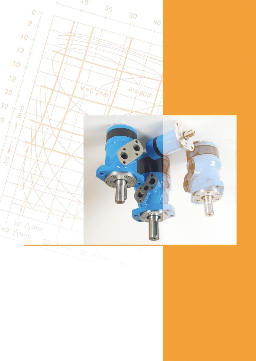
Hydraulic motor type MM. Hydraulic motor type MR SPOOL VALVE HYDRAULIC MOTORS. Quality assured company - ISO 9001 Certified
 SOOL VALVE HYDAULI MOOS Quality assured company - ISO 9001 ertified SOOL VALVE - he distributor valve has been integrated with the output shaft. he valve has hydrodynamic bearings, and has infinite life
HYDRAULIC MOTORS EPM. Cutaway of EPM Motor. Cutaway of EPMN Motor. EPM, EPMW(N) Series with Check Valves A. EPM 25, 32, 40 Series without Check Valves
 Series with Check Valves A. EPM 25, 32, 40 Series without Check Valves") HYDRAULIC EPM The series of EPM motors have a low speed, high torque capability. Converting hydraulic energy into mechanical energy they are used where the power up to 11 kw is needed. These units provide
HYDRAULIC EPM The series of EPM motors have a low speed, high torque capability. Converting hydraulic energy into mechanical energy they are used where the power up to 11 kw is needed. These units provide
HEAVY DUTY HYDRAULIC MOTORS
 HEAVY DUTY HYDRAULIC MTRS CNTENTS Page Hydraulic Motors Series MSWM... 4 Hydraulic Motors Series MTK... 8 Hydraulic Motors Series MTM... 17 Hydraulic Motors Series TMF... 9 Hydraulic Motors Series MVM...
HYDRAULIC MOTORS HP APPLICATION GENERAL. » Conveyors» Feeding mechanism of robots and manipulators» Metal working machines» Textile machines
 HYDRAULIC HP APPLICAION» Conveyors» Feeding mechanism of robots and manipulators» Metal working machines» extile machines» Agricultural machines» Food industries» Grass cutting machinery etc. CONENS Specification
HEAVY DUTY HYDRAULIC MOTORS
 HEAVY DUY HYDRAULIC MRS CNENS Page Hydraulic Motors Series MLHSEM... 4 Hydraulic Motors Series MK... 8 Hydraulic Motors Series MLHM... 17 Hydraulic Motors Series MF... 9 Hydraulic Motors Series MVM...
HYDRAULIC MOTORS GENERAL INFORMATION
 GENERAL INFORMATION MGL... Document: HM-1-Dec 2012 Applications: -Agricultural harvesters and seeders -Conveyors -Machine tools -Food industries -Turn equipment -Brush drivers -Sweepers and floor polishers
DISC VALVE HYDRAULIC MOTORS
 LHS LH LHV DISC VALVE HYDRAULIC CONENS Page Hydraulic otors Series LHS... 4 Hydraulic otors Series LH... 2 Hydraulic otors Series LHV... 9 Hydraulic otors Series LHHW... 1 otor Special Features... 7 otors
TMF 600 ( cm³/rev.)
") HYDRAULIC COMPONENTS HYDROSTATIC TRANSMISSIONS GEARBOXES - ACCESSORIES Certified Company ISO 9001-14001 ISO 9001 Via M. L. King, 6-41122 MODENA (ITALY) Tel: +39 059 415 711 Fax: +39 059 415 729 / 059 415
HYDRAULIC COMPONENTS HYDROSTATIC TRANSMISSIONS GEARBOXES - ACCESSORIES Certified Company ISO 9001-14001 ISO 9001 Via M. L. King, 6-41122 MODENA (ITALY) Tel: +39 059 415 711 Fax: +39 059 415 729 / 059 415
CONTENT Axial Piston Motors and Pumps Fixed Displacement. Technical Specification Guide...2. Hydraulic motor MAP Hydraulic motor MAP50...
 CONTENT CONTENT Aial Piston Motors and Pumps Fied Displacement PAGE Technical Specification Guide...2 Hydraulic motor...6 Hydraulic motor MAP5...1 Hydraulic motor MAP1...2 MAP5 Hydraulic pump PAP5...29
HYDRAULIC DISC BRAKES LB, LBS, LBV- Wet
 HYRULI IS S LB, LBS, LBV- Wet PPLITION» Heavy uty machinery» Wheel drives» Material handling» Mining» gricultural machines» onveyors» oor openers and swing drives etc. GENERL Fluid type O O Temperature
TPF 60 (36,16 49,94 cm³/rev.)
") HYDRAULIC COMPONENTS HYDROSTATIC TRANSMISSIONS GEARBOXES - ACCESSORIES Certified Company ISO 9001-14001 ISO 9001 Via M. L. King, 6-41122 MODENA (ITALY) Tel: +39 059 415 711 Fax: +39 059 415 729 / 059 415
HYDRAULIC COMPONENTS HYDROSTATIC TRANSMISSIONS GEARBOXES - ACCESSORIES Certified Company ISO 9001-14001 ISO 9001 Via M. L. King, 6-41122 MODENA (ITALY) Tel: +39 059 415 711 Fax: +39 059 415 729 / 059 415
C9: BMM, BMP, BMR, BMH, BMJ Series & Valves CONTENT. Usage Guide 2. BMM Series Hydraulic Motors 3. BMP Series Hydraulic Motors 11
 C9: BMM, BMP, BMR, BMH, BMJ Series & Valves CONTENT Usage Guide 2 BMM Series Hydraulic Motors 3 BMP Series Hydraulic Motors 11 BMR Series Hydraulic Motors 24 BMH Series Hydraulic Motors 35 BMJ Series Hydraulic
HYDRAULIC DISC BRAKES LB, LBS, LBV- Wet
 HYRULI IS S LB, LBS, LBV- Wet PPLITION» Heavy uty machinery» Wheel drives» Material handling» Mining» gricultural machines» onveyors» oor openers and swing drives etc. GENERL Fluid type O O Temperature
HYDRAULIC DISC BRAKES LB, LBS, LBV- Wet
 HYRAULI IS S LB, LBS, LBV- Wet APPLIAION» Heavy uty machinery» Wheel drives» Material handling» Mining» Agricultural machines» onveyors» oor openers and swing drives etc. GENERAL Fluid type O O emperature
OMP Hydraulic Motor Versions
 Versions VERSIONS Mounting flange Shaft Port size European version US version Side port version End port version Flange port version G 1 /2 X X X No No OMP Cyl. 25 mm G 1 /2 X X X Yes No OMP G 1 /2 X X
OMEW Hydraulic Motor Versions
 Versions VERSIONS Mounting flange Wheel Shaft Port size European version US version Clockwise shaft rotation (CW version) 1) Counter clockwise shaft rotation (CCW version) 1) Tapered 35 mm G 1 /2 X X X
HYDRAULIC MOTORS MH APPLICATION GENERAL. » Agriculture machines» Food industries» Mining machinery etc. » Conveyors
 HYDRAULIC APPLICATION» Coveyors» Feedig mechaism of robots ad maipulators» etal workig machies» Textile machies» Agriculture machies» Food idustries» iig machiery etc. CONTENTS Specificatio data... 77
US version. Drain connection
 Versions OMT Versions Mounting flange Standard flange Shaft Port size Europea n version US version Drain connection Check valve Low pressure release High pressure release Cyl. 4 mm G 3/4 X Yes Yes OMT
Spool Valve Hydraulic Motors. Spool Valve motors incorporate the proven orbit motor principle to provide high torque at low speeds.
 Spool Valve Hydraulic Motors Spool Valve motors incorporate the proven orbit motor principle to provide high torque at low speeds. B-i Spool Valve Motors Highlights Product Description Char-Lynn spool
SCM SAE. Other advantages: Sunfab s SCM SAE is a range of robust axial piston motors especially suitable for mobile hydraulics.
 Sunfab s SCM 010-130 SAE is a range of robust axial piston motors especially suitable for mobile hydraulics. SCM 010-130 SAE is of the bent-axis type with spherical pistons. The design results in a compact
High Torque Low Speed Motors MR - MRE
 High Torque Low Speed Motors MR - MRE Calzoni Radial Piston Technology aerospace climate control electromechanical filtration fluid & gas handling hydraulics pneumatics process control sealing & shielding
SCM ISO. SCM ISO is a range of robust axial piston motors especially suitable for mobile hydraulics.
 SCM 010-130 ISO is a range of robust axial piston motors especially suitable for mobile hydraulics. SCM 010-130 ISO is of the bent-axis type with spherical pistons. The design results in a compact motor
MOTOR SCM ISO
 MOTOR SCM 012-130 ISO SCM 012-130 ISO is a range of robust axial piston motors especially suitable for mobile hydraulics. SCM 012-130 ISO is of the bent-axis type with spherical pistons. The design results
Size CC-A Flange Options-B Shaft Options-C Ports Features. SAE A 2 Bolt - (H2) 4 Bolt Magneto (H6) 4 Bolt Square (H4)
 4 Bolt Magneto (H6) 4 Bolt Square (H4)") Gerolor Motors S Series Size CC-A Flange Options-B Shaft Options-C Ports Features S S S S S S S S2 2 S31 31 S0 0 SAE A 2 Bolt - (H2) 4 Bolt Magneto (H6) 4 Bolt Square (H4) 1.0" Keyed (R) mm Keyed (A) 1.0'
Gerolor Motors S Series Size CC-A Flange Options-B Shaft Options-C Ports Features S S S S S S S S2 2 S31 31 S0 0 SAE A 2 Bolt - (H2) 4 Bolt Magneto (H6) 4 Bolt Square (H4) 1.0" Keyed (R) mm Keyed (A) 1.0'
SCM M2. Other advantages:
 Sunfab s SCM 025-108 M2 is a range of robust axial piston motors with cartridge flange especially suitable for winch-, slewing-, wheel- and track drives. SCM 025-108 M2 is of the bent-axis type with spherical
MOTOR SCM M2
 MOTOR SCM 025 108 M2 Sunfab SCM M2 is a range of robust axial piston motors especially suitable for winch-, slewing-, wheeland track drives. Sunfab SCM M2 is of the bent-axis type with spherical pistons.
Low Speed High Torque Motors
 Low Speed High Torque Motors Catalogue HY29-0503/UK TABLE OF CONTENTS Table of contents Features General information Functional description Technical data 3 4 4 5 6 FRAME SIZE P Operating diagrams Overall
RE / Gerotormotors (Low Speed High Torque Motors) Type GMS, GMSS, GMSW, GMT, GMTS, GMTW. Hydraulik Nord. Contents 1/26
 Type GMS, GMSS, GMSW, GMT, GMTS, GMTW. Hydraulik Nord. Contents 1/26") RE14 6/3.96 Gerotormotors (Low Speed High Torque Motors) Type GMS, GMSS, GMSW, GMT, GMTS, GMTW RE 14 6/3.96 Standard motor type GMS Standard motor type GMT Short motor type GMTS Contents Name page Characteristics,
RE14 6/3.96 Gerotormotors (Low Speed High Torque Motors) Type GMS, GMSS, GMSW, GMT, GMTS, GMTW RE 14 6/3.96 Standard motor type GMS Standard motor type GMT Short motor type GMTS Contents Name page Characteristics,
SPARE PARTS FOR HYDRAULIC MOTORS TYPE MR...- series 4, XX
 SPARE PARTS FOR HYDRAULIC MOTORS TYPE MR...- series 4, 41513800XX 1 SCREW For MR (F)...(D) M6x20-12.9 MP08V019 6 For MRQ M5x16-12.9 MP08V017 6 For MRQ U M5x16-12.9 MP08V017 8 2 SPRING WASHER 6H (without
Spool Valve Hydraulic Motors Series J
 Spool Valve Hydraulic Motors Series J 10.201 inspired hydraulics. Änderungen und Druckfehler vorbehalten 10.201 EN EATON_Motoren J Series english J Series Highlights Thrust Bearing Bushing Port B Port
J Series (129-) Highlights
 Highlights") Highlights Features: Constant clearance Geroler set Integrated check valves Thrust Bearing Bushing Port B Port A Self-lubricating shaft bushing High-strength rigid components Increased valve seal lands
Highlights Features: Constant clearance Geroler set Integrated check valves Thrust Bearing Bushing Port B Port A Self-lubricating shaft bushing High-strength rigid components Increased valve seal lands
SCM DIN. Other advantages:
 SCM 012-130 DIN SCM 012-130 DIN is a series of axial piston motors particularly suitable for mobile hydraulics. SCM 012130 DIN is of the bent-axis type with spherical pistons. Other advantages: The design
Fixed Displacement Bent Axis Axial Piston Motors TMB 700
 HYDRAULIC COMPONENTS HYDROSTATIC TRANSMISSIONS GEARBOXES - ACCESSORIES Certified Company ISO 9001:2015-14001:2015 ISO 9001:2015 Certificate N 12-Q-0200545-TIC ISO 14001:2015 Certificate N 12-E-0200545-TIC
SCM SAE. Other advantages: Sunfab s SCM SAE is a range of robust axial piston motors especially suitable for mobile hydraulics.
 Sunfab s SCM 010-130 SAE is a range of robust axial piston motors especially suitable for mobile hydraulics. SCM 010-130 SAE is of the bent-axis type with spherical pistons. The design results in a compact
TPV Variable Displacement Closed Loop System Axial Piston Pump HY-TRANS THE PRODUCTION LINE OF HANSA-TMP HT 16 / M / 501 / 1009 / E
 HYDRAULIC COMPONENTS HYDROSTATIC TRANSMISSIONS GEARBOXES - ACCESSORIES HY-TRANS THE PRODUCTION LINE OF HANSA-TMP Via M. L. King, 6-41122 MODENA (ITALY) Tel: +39 059 415 711 Fax: +39 059 415 729 / 059 415
Variable displacement axial piston pumps,
 Variable displacement axial piston pumps, Edition: 04/04.2000 Replaces: 04/10.99 DISPLACEMENTS From To PRESSURE Max. continuous Max. intermittent Max. peak 29 cm 3 /rev 73 cm 3 /rev 280 bar 315 bar 350
VINCKE HYDRAULIC PUMPS
 : VNK BA10VS 21 Variable displacement axial piston pump of swashplate design for hydraulic open circuit systems. Flow is proportional to drive speed and displacement. It can be infinitely varied by adjustment
RE / Gerotormotors (Low Speed High Torque Motors) Type GMP, GMR, GMVD. Hydraulik Nord. Contents 1/32. Replaces:
 Type GMP, GMR, GMVD. Hydraulik Nord. Contents 1/32. Replaces:") Gerotormotors (Low Speed High Torque otors) Type GP, GR, GVD RE 14 7/3.96 RE 14 7/11.96 Replaces: 3.96 Characteristics: Very smooth running, even at low speeds Wide speed range Constant output torque over
Gerotormotors (Low Speed High Torque otors) Type GP, GR, GVD RE 14 7/3.96 RE 14 7/11.96 Replaces: 3.96 Characteristics: Very smooth running, even at low speeds Wide speed range Constant output torque over
Eaton Char-Lynn Low Speed, High Torque Motors. Orbit motor
 Eaton Char-Lynn Low Speed, High Torque Motors Orbit motor Table of Contents Description Page No. H & S Series 3 Features 3 Model code 3 H Series 4-9 Specifications 4 Performance 5 Dimensions and mount
External gear pump Series G
 External gear pump Series G RE 10 093/04.14 Replace RE 10 093/06.13 AZPG-22 Fixed pumps V = 22.5...100 cm 3 / rev Overview of contents Contents Page General 2 Product overview 3 Ordering code single pumps
High Torque Low Speed Motors MRT - MRTE - MRTF
 High Torque Low Speed Motors MRT - MRTE - MRTF Calzoni Radial Piston Technology aerospace climate control electromechanical filtration fluid & gas handling hydraulics pneumatics process control sealing
Orbital Motors OMS, OMT and OMV Orbital Motors
 MKING MODERN LIVING POSSIBLE Technical Information Orbital Motors OMS, OMT and OMV Orbital Motors powersolutions.danfoss.com Revision history Table of revisions Date Changed Rev November 214 Converted
YMSY. Advanced design in disc distribution flow,which can automatically compensate in operating with high volume efficiency and long life.
 The series motors adapts an advanced ROLLER gear set designed with disc distribution flow and high pressure. This motor series uses the ROTOR gear type manufactured with most advanced technology and quality
ACCESSORIES CONTENTS. HYDRAULIC DISC BRAKE for MP, MR and MS type LB/
 ESSORIES ONTENTS age HYDRULI DIS RKE for M, MR and MS type L/288... 3 HYDRULI DIS RKE for MSS type LS/289(290) and MSV type LV/289(290)... 6 HYDRULI DIS RKE for MTS type LS/314(315) and MTV type LV/314(315)...
HYDRAULIC DISC BRAKES LB, LBS, LBV- Wet
 HYRULI IS BRKES LB, LBS, LBV Wet PPLITIN» Heavy uty machinery» Wheel drives» Material handling» Mining» gricultural machines» onveyors» oor openers and swing drives etc. GENERL Fluid type Temperature range,
TPV Variable Displacement Closed Loop System Axial Piston Pump THE PRODUCTION LINE OF HANSA-TMP HT 16 / M / 852 / 0815 / E
 HYDRAULIC COMPONENTS HYDROSTATIC TRANSMISSIONS GEARBOXES - ACCESSORIES Certified Company ISO 9001-14001 ISO 9001 Via M. L. King, 6-41122 MODENA (ITALY) Tel: +39 059 415 711 Fax: +39 059 415 729 / 059 415
TXV - Characteristics
 TXV - Characteristics TXV pumps are available in 11 models from to 150 cc/rev maximum displacement. Pump reference Direction of rotation Maximum displac. (1) Max. operating pressure Max. peak pressure
À cylindrée fixe Gamme MAP 50
 pplications Moteur à pistons axiaux M+S À cylindrée fixe Gamme MP Cylindrée de 6,6 à cm Vitesse de rotation maxi de tmin Couple maxi danm Puissance maxi 6 Kw ébit d huile maxi : 9 lmin Charge axiale maxi
HYDRAULIC OIL PUMPS AND MOTORS PRODUCT CATALOG. Hybel - Hydraulic Oil Pumps and Motors
 HYDRAULIC OIL PUMPS AND MOTORS PRODUCT CATALOG Hybel Hydraulic Oil Pumps and Motors HYDRAULIC OIL PUMPS AND MOTORS Contents CONTENTS About us.... 04 Products Line.... 06 Configure your product.... 08 Aluminibeta
External Gear Pumps Series F
 External Gear Pumps Series F RA 10089/08.11 Replaces: RA 10097 1/60 AZPF-... Fixed pumps Size 4.0...28 cm 3 /rev (.25-1.71 in 3 /rev) Overview of contents Contents Page General 2 Product overview 3 single
Axial Piston Variable Double Pump A8VO
 Axial Piston Variable Double Pump A8VO RE 93010/03.09 1/40 Replaces: 11.07 Data sheet Series 61 / 63 Sizes 55...200 Nominal pressure 350 bar Peak pressure 400 bar for open circuit Contents Ordering Code
VPPM /110 ED VARIABLE DISPLACEMENT AXIAL-PISTON PUMPS OPERATING PRINCIPLE TECHNICAL SPECIFICATIONS HYDRAULIC SYMBOL
 16 100/110 ED VPPM VARIABLE DISPLACEMENT AXIAL-PISTON PUMPS OPERATING PRINCIPLE The VPPM pumps are variable displacement axial-piston pumps with variable swash plate, suitable for applications with open
Axial Piston Fixed Motor A2FM
 Axial Piston Fixed Motor A2FM RE 91001/06.2012 1/46 Replaces: 09.07 Data sheet Series 6 Size Nominal pressure/maximum pressure 5 315/350 bar 10 to 200 400/450 bar 250 to 1000 350/400 bar Open and closed
ENGINEERING DATA. High Torque, Low Speed Motors H, S, 2000, 6000, and 10,000 Series. w w w. F l u i D y n e F P. c o m
 ENGINEERING DATA High Torque, Low Speed Motors H, S, 2000, 6000, and 10,000 Series Interchangeable with: Charlynn White Ross Parker Danfoss w w w. INDEX Cross Reference Guide...2 Introduction...3 H-Series...4
Variable displacement axial piston pumps,
 LVP 04 T E Variable displacement axial piston pumps, Edition: 04/04.2000 Replaces: 04/10.99 DISPLACEMENTS From To PRESSURE Max. continuous Max. intermittent Max. peak 29 cm 3 /rev 73 cm 3 /rev 280 bar
Size CC-A Flange Options-B Shaft Options-C Ports Features. SAE A 2 Bolt - (E2) 4 Bolt Square (E4)
 4 Bolt Square (E4)") Gerolor Motors BMRS Series Size CC-A Flange Options-B Shaft Options-C Ports Features 100 100 1 1 1 1 200 200 2 3 2 3 3 3 SAE A 2 Bolt - (E2) 4 Bolt Square (E4) 1-1/4" Keyed (G) 32mm Keyed (B) 1-1/4' 14T
Gerolor Motors BMRS Series Size CC-A Flange Options-B Shaft Options-C Ports Features 100 100 1 1 1 1 200 200 2 3 2 3 3 3 SAE A 2 Bolt - (E2) 4 Bolt Square (E4) 1-1/4" Keyed (G) 32mm Keyed (B) 1-1/4' 14T
HYDRAULICS VINCKE HYDRAULIC PUMPS
 VINCKE HYDRAULIC PUMPS TECH-VHP200.1 index 3 link to your page / link a su página Gear pumps Introduction 3 Group 0 3 Group 1 3 Group 2 3 Group 3 4 6 7 12 18 Variable displacement pumps 21 Hand pumps 3
Axial Piston Fixed Pump A2FO
 Electric Drives and Controls Hydraulics Linear Motion and Assembly Technologies Pneumatics ervice Axial Piston Fixed Pump A2FO RE 91401/03.08 1/24 Replaces: 09.07 Technical data sheet eries 6 izes Nominal
YMTE SPECIFICATION DATA
 SPECIFICATION DATA For individual motor performance charts consult equivalent YMT series data DISTRIBUTION TYPE GEOMETRIC DISPLACEMENT MAX. SPEED RPM MAX. TORQUE [IN. LB.] N*M MAX. OUTPUT [HP] KW MAX.
Gear Pumps / Motors. Series PGP / PGM Fixed Displacement Pumps, Cast-Iron and Aluminium Designs
 Gear Pumps / Motors Series PGP / PGM Fixed Displacement Pumps, Cast-Iron and Aluminium Designs Table of contents Heavy-duty Pumps and Motors Series PGP, PGM Contents Page Series 500 Aluminium Table of
MOMV SERIES HYDRAULIC MOTOR
 MOMV SERIES HYDRAULIC MOTOR MOMV series motor adapt the advanced Geroler gear set designed with disc distribution flow and high pressure.the unit can be supplied the individual variant in operating multifunction
Wide range of hydraulic motors & valves BM2 BM1 H PORT BM1 LINE PORT BM1 S PORT HMM BM4 BM3 WHEEL MOTOR MOTOR WITH SPEED SENSOR
 Wide range of hydraulic motors & valves BM2 BM1 H PORT BM1 LINE PORT BM1 S PORT HMM BM4 BM3 WHEEL MOTOR MOTOR WITH SPEED SENSOR 4K BM5 BEARINGLESS BM5 BMT BM6 BEARINGLESS BM6 MOTOR BALANCE VALVE MOTOR
AP212 Gear Pumps. Standard and Low Noise series. Reference: 200-P EN-03 1/60. Issue:
 Gear Pumps Standard and Low Noise series Reference: 2-P-99123-EN-3 Issue: 9.215 1/6 Contents Page 1 General information... 4 1.1 External gear pumps components... 5 1.2 Example of typical sound pressure
Axial Piston Variable Pump A4VG
 Electric Drives and Controls Hydraulics Linear Motion and Assembly Technologies Pneumatics Service Axial Piston Variable Pump A4VG RE 92003/03.09 1/64 Replaces: 09.07 Data sheet Series 32 Sizes 28...250
镇江液压件厂有限责任公司 BMV SERIES HYDRAULIC MOTOR BMV 315 BMV 400 BMV 500 BMV 630 BMV 800 BMV
 BMV SERIES HYDRAULIC MOTOR BMV series motor adapt the advanced Geroler gear set designed with disc distribution flow and high pressure.the unit can be supplied the individual variant in operating multifunction
TPV Variable Displacement Closed Loop System Axial Piston Pump THE PRODUCTION LINE OF HANSA-TMP HT 16 / M / 851 / 0813 / E
 HYDRAULIC COMPONENTS HYDROSTATIC TRANSMISSIONS GEARBOXES - ACCESSORIES THE PRODUCTION LINE OF HANSA-TMP Variable Displacement Closed Loop System CONTENTS General Information... Order Code... Manual Control
Disc Valve Hydraulic Motors Series 4000
 Disc Valve Hydraulic Motors Series 0 10.20 inspired hydraulics. Änderungen und Druckfehler vorbehalten 10.20 EN EATON_Motoren english Highlights Features 10 displacements, a variety of mounting flanges
FIXED DISPLACEMENT HYDRAULIC VANE PUMPS BV SERIES
 BV FIXED DISPLACEMENT HYDRAULIC VANE PUMPS BV SERIES Versatility, power, compactness and low running costs are the main characteristics of B&C vane pumps. All the components subject to wear are contained
S Series (103-) Highlights B-3. Description. Specifications
 Highlights B-3. Description. Specifications") Highlights New, improved design! Features: Constant clearance Geroler design Three moving components (gerotor, drive, shaft) Optimized drive running angle Three-zone pressure design (inlet, return and
Highlights New, improved design! Features: Constant clearance Geroler design Three moving components (gerotor, drive, shaft) Optimized drive running angle Three-zone pressure design (inlet, return and
Axial Piston Variable Pump AA4VG
 Electric Drives and Controls Hydraulics Linear Motion and Assembly Technologies Pneumatics Service Axial Piston Variable Pump AA4VG RA 92003-A/06.09 1/64 Replaces: 03.09 Data sheet Series 32 Size 28...
Vane motor high performance hydraulic series M5B - M5BS - M5BF
 Vane motor high performance hydraulic series M5B - M5BS - M5BF Publ. 2 - AM172 - B 1 / 25 / FB Replaces : 2 - AM172 - A L11-2172 - 2 CHARACTERISTICS - M5B* SERIES LOW NOISE MOTOR 12 vanes and a patented
External Gear Pumps Series F
 External Gear Pumps Series F AZPF-... Fixed pumps V = 4.0...28 cm 3 /rev Overview of contents ontents Page General 2 Product overview 3 single pumps 4 multiple pumps 5 rive shaft 6 Front cover 7 Line ports
External Gear Pumps Series F
 External Gear Pumps Series F RE 10 089/02.07 Replaces: Series F Issue 04.04 AZPF-... Fixed pumps V = 4.0...28 cm 3 /rev Overview of contents ontents Page General 2 Product overview 3 single pumps 4 multiple
HYDRAULIC MOTORS EPMSY
 HYDRAULIC NEW is the ew hydraulic motor i a family of "disc valve" series which has dimesios ad moutig data the same as at hydraulic motors type EPS. This motor is described with % hidger techical data-max.
Disc Valve Hydraulic Motors 4000 Compact Series
 Disc Valve Hydraulic Motors 10.2014 inspired hydraulics. Änderungen und Druckfehler vorbehalten 10.2014 EN EATON_Motoren english Port B Port A Features Shuttle Valve with Back- Pressure Relief Valve Highlights
AP212HP Cast Iron Gear Pumps
 Cast Iron Gear Pumps Standard and Low Noise series Reference: 200-P-991236-EN-01 Issue: 09.2016 1/56 Contents Page 1 General information... 5 1.1 External gear pumps components... 6 1.2 Technical data...
OMEW Standard and with Low Speed Option. Orbital Motors. Technical Information
 Standard and with Low Speed Option Orbital Motors Technical Information Contents Revision History Table of Revisions Date Page Changed Rev Jan 2009 Many major change BA Mar 2010 16 Japan location BB Contents
PVE /117 ED VARIABLE DISPLACEMENT VANE PUMPS WITH DIRECT PRESSURE ADJUSTMENT SERIES 30 OPERATING PRINCIPLE TECHNICAL SPECIFICATIONS
 14 110/117 ED PVE VARIABLE DISPLACEMENT VANE PUMPS WITH DIRECT PRESSURE ADJUSTMENT OPERATING PRINCIPLE The PVE pumps are variable displacement vane pumps with direct pressure regulator. The pump group
VIS (Valve-In-Star) Hydraulic Motor
 Hydraulic Motor") VIS (Valve-In-Star) Hydraulic Motor VIS 30 Series VIS 40 Series VIS 45 Series The next step in the evolution of low speed high torque (LSHT) hydraulic motors. EATON Low Speed High Torque Motors E-MOLO-MC001-E5
VIS (Valve-In-Star) Hydraulic Motor VIS 30 Series VIS 40 Series VIS 45 Series The next step in the evolution of low speed high torque (LSHT) hydraulic motors. EATON Low Speed High Torque Motors E-MOLO-MC001-E5
UŽSISAKYKITE internetu telefonu el. paštu
 Features Axial piston pump MA10VO in swashplate design is used in open loop circuits. Flow is proportional to drive speed and displacement. By adjusting the position of the swashplate it is possible to
Disc Valve Hydraulic Motors 2000 Series
 Disc Valve Hydraulic Motors 10.2014 inspired hydraulics. Änderungen und Druckfehler vorbehalten 10.2014 EN EATON_Motoren english Highlights Port A Features Three zone design for longer life and true bi-directionality.
Axial piston variable pump A4VG Series 32. Europe. RE-E Edition: Replaces:
 Axial piston variable pump A4VG Series 32 Europe RE-E 92003 Edition: 04.2016 Replaces: 06.2012 High-pressure pump for applications in a closed circuit Size 28 to 125 Nominal pressure 400 bar Maximum pressure
Orbital Motors Type OMP, OMR and OMH. Technical Information
 Orbital Motors Type OMP, OMR and OMH Technical Information OMP, OMR and OMH A Wide Range of Hydraulics Motors F 301 245 A Wide Range of Hydraulic Motors Sauer-Danfoss is a world leader within production