Technical Manual Part 1 Assembly and Operating Instruction for all PegaSys Components
|
|
|
- Todd Mitchell
- 5 years ago
- Views:
Transcription


1 PegaSys Intelligent Access Control System Technical Manual Part 1 Assembly and Operating Instruction for all PegaSys Components
2
3 The documentation has been written for persons that install and commission the devices described in this documentation. Symbols and designations Operationally important information that has to be observed. Additional information, e.g. notes. The devices described in the documentation comply with the electrotechnical EN and CE standards effective at the time of printing. Device modifications are not permitted. All technical information herein is accurate at the time of printing. It is, however, not to be deemed in any way to be a specific warranty of certain characteristics. Disposing of the product Dispose of the product in accordance with the laws and regulations that apply in your country. Disposing of batteries Dispose of the batteries in accordance with the laws and regulations that apply in your country. Dispose of the batteries yourself at a collecting point, or send the battery to the supplier of the product, with the battery contacts insulated and with the note "Old batteries for disposal" added to the shipment. Offline components Within the context of general information that applies to devices of the PegaSys Door Fittings, PegaSys Lock Cylinders or PegaSys Locker Locks series, the devices are generically called offline components. Reference number: Printed on: Copyright 2014
4
5 Contents i Contents 1 Electronic Door Fittings of the PegaSys Series Design of the electronic door fitting Design of the Office series Technical data Technical data PegaSys Technical data of the Office series Dimensions: PegaSys door fitting Dimensions: Interior fittings Dimensions: Door handle series Applicable reading technologies: Assembly and installation Preparations for installation Installation types Function check - mechanical components Battery change at door fitting Switchover to daylight saving time, leap year Cleaning instructions Resetting the door fitting Electronic Lock Cylinders of the PegaSys Series Introduction Components of an electronic lock cylinder Scope of delivery Technical data Installation/dismantling Notes on installation Installing the cylinder body Installing the electronic knob Dismantling the electronic knob Installing the electronic knob for a furniture lock Dismantling the electronic knob for a furniture lock Operation Notes on use Short-time release Permanently open mode Special signals Batteries Low battery warning levels Battery exchange Low-power adapter: Exchanging empty batteries Device reset PegaSys Locker Locks Scope of delivery and intended use Applicable reading technologies Installation Initial operation Prerequisites Removing the battery holder Inserting the battery... 53
6 ii Contents Configuring the locker lock Opening and closing the locker lock Battery change Low battery warning levels Resetting the locker lock Cleaning Replacement parts and accessories Technical data PegaSys Operating Modes Applicable reading technologies: Switchover to daylight saving time, leap year »Teach in«pin Code operating mode »Teach in«(p 100) operating mode Configuring the PegaSys Offline component for "Teach in" Opening doors Visual and audible signals »NetworkOnCard«(P 200 / P 300) operating mode with an access control system Recommended procedure for setting up a new access control system Single door authorization <-> Group authorization Credentials and booking types Administration of the PegaSys Offline components Opening doors Visual and audible signals Glossary 75 6 Index 77


7 Installation Instructions for PegaSys Electronic Door Fittings
8

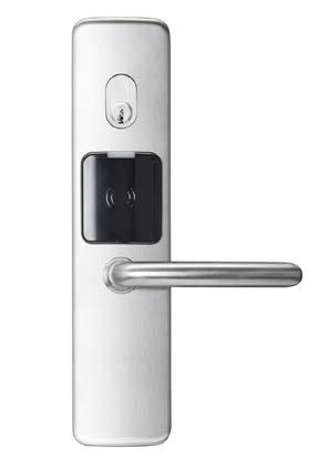
9 Electronic Door Fittings of the PegaSys Series 5 1 Electronic Door Fittings of the PegaSys Series Electronic door fittings of the PegaSys series are used to control the access at individual doors. A door secured with an electronic door fitting can only be opened after you have proven that you are authorized to enter, by means of a valid credential. Exception: PegaSys PIN code This variant of an electronic door fitting is run exclusively with codes that you enter on the built-in keypad. You can program the door fitting with codes and assign a certain function to each code. During operation, you can then, for instance, enter a certain code for door lock release. You can find more details on PegaSys PIN-Code in a separate manual. 1.1 Design of the electronic door fitting
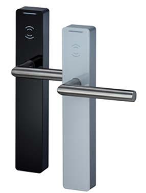
10 6 Electronic Door Fittings of the PegaSys Series The electronic door fitting consists of the following components: 1 Electronics 5 Mounting plate, stainless steel 2 Lock box with coupling mechanism 6 Battery case 3 Adapter for square spindle 7 Housing, stainless steel 4 Square spindle for lever handle The PegaSys 2.1 fittings are supplied with door handles from the NT 181/EST 41, NT 191/EST 51, NT 291/EST 21, NT 1182/EST 1141, NT 1292/EST 1121 or 1171 series, or with pivoted support and additional square spindle set. The door handle and the stainless steel exterior door plate are permanently connected with each other by a plain bearing with minimum tolerance and a retaining ring. The fittings of the Office series are supplied with door handles from the 291, 1291, 281 and 1281 series Design of the Office series Design of the electronic door fitting of the Office Series. Right side: Electronic door fitting, battery case and lock box Left side: Interior fitting 1.2 Technical data Technical data PegaSys 2.1 General data Housing material Total weight Available backset Square spindles Center-to-center distance Locks Emergency opening Solid housing made of high-grade steel, 1.8 mm thick PegaSys B 2.1: approx g PegaSys S 2.1: approx g Min. 30 mm 7, 7.5, 8, 8.5, 9, 10 mm 70, 72, 74, 78, 85, 88, 90, 92 mm Standard locks equipped with lever retracting the latch bolt to cylinder locks, self-locking panic locks, locks with "security function" E By means of equipped cylinders or simultaneously locking mechanical cylinders (optionally also available without cylinder cutout)
11 Electronic Door Fittings of the PegaSys Series 7 General data Fire protection Signaling Booking memory Certified according to DIN for fire protection and smoke control doors Visual and audible signals Standards DIN 18273, EN 179 Roll storage for the last 2000 bookings and 100 system messages Power supply Battery Battery life PegaSys B 2.1: 3 x AA lithium batteries PegaSys S 2.1: 3 x AAA lithium batteries Up to 50,000 opening cycles, depending on the reading technology, the design, the installation conditions and the operating modes. Environmental conditions Operating temperature (*) -20 C to +60 C Large variations in temperature will reduce the lifetime of the batteries. Protection category (*) Certified IP 55 Humidity (*) 95 %, non-condensing (*) Basic requirement: Inside battery case and outdoor kit Technical data of the Office series General data Material Total weight External dimensions including electronics (HxWxD) Internal dimensions excluding electronics (HxWxD) Available backset Square spindles Center-to-center distance Locks Emergency opening Signaling Booking memory Color Exterior fitting and interior fitting: Cast metal housing with top quality powder coating, glass front and fixed pivot handle made of stainless steel Approx grams 295 mm x 52 mm x 30 mm 295 mm x 52 mm x 20 mm Min. 30 mm 8 mm, 8.5 mm, 9 mm, 10 mm, (others available on request) 70, 72, 74, 78, 85, 88, 90, 92, 94 mm Standard locks with retracting latchbolt on cylinder (exchange); panic locks with self-locking mechanism By means of equipped cylinders or simultaneously locking mechanical cylinders (optionally also available without cylinder cutout) Visual and audible user information Roll storage for the last 2000 bookings and 100 system messages Black or white
12 8 Electronic Door Fittings of the PegaSys Series Power supply Battery Battery life Battery warning Depending on type, 3 AAA or AA batteries Up to 40,000 opening cycles, depending on the reading technology and the battery case used, as well as the various installation conditions and operating modes. Visual and audible (optional) low battery warning; battery status is reported to control software Environmental conditions Operating temperature (*) 0 C to +40 C Large temperature fluctuations will reduce the battery life. Protection category IP 20 Humidity 95 %, non-condensing Dimensions: PegaSys door fitting PegaSys door fitting: Wide version PegaSys door fitting: Narrow version for doors with tubular frames Office exterior fitting
13 Electronic Door Fittings of the PegaSys Series Dimensions: Interior fittings Interior fittings Version: 230 mm Version: 195 mm Interior fittings for doors with tubular frames Office interior fitting
14 10 Electronic Door Fittings of the PegaSys Series Dimensions: Door handle series Door handle series for wide door fittings 181 series 191 series 281 series 291 series Door handle series for doors with tubular frames 1171 series 1182 series 1282 series 1292 series Door handle series for Office series 281 series 291 series 1282 series 1292 series
15 Electronic Door Fittings of the PegaSys Series Applicable reading technologies: The PegaSys Offline components support the following reading technologies for the credentials: MIFARE Classic MIFARE DESFire LEGIC Prime LEGIC Advant Hitag1 (availability depends on the type of PegaSys Offline component) 1.3 Assembly and installation Preparations for installation Configure the PegaSys Offline devices before installing them at their final location.


 Drilling")

16 12 Electronic Door Fittings of the PegaSys Series Preparations for installation: Tools 1. Required tools Cordless screw driver / hand drill Flat-bladed screw driver Phillips screw driver Torx screw driver Drill, 7 mm Square hole (from left) 2. Optional tools Drilling template, long plate (Germany) Drilling template, long plate (France) Drilling template, short plate, rose fitting Mounting cylinder Flexible square hole, 3 mm (available from specialized retailers) Flexible Torx screw driver with cover plate lifter (from left) 3. Mounting block and Toolkit


17 Electronic Door Fittings of the PegaSys Series 13 Preparations for installation: Drilled hole in door Check the door hole with a caliper or gauge. Recommendation: The diameter should be min. 28 mm. A diameter of 28 mm is required for screw-on mounting on doors with tubular frames, as well as for exterior fittings without a key hole. Min. diameter: 23 mm Scribing templates The following scribing templates are included in the scope of delivery: PegaSys B 2.x PZ 72 mm PZ 92 mm PegaSys B 2.x PZ 78, 88 mm KABA 74, 78 mm Long plate: Germany PZ 72, 78, 88, 92 mm RZ 22 (KABA), 78 mm


18 14 Electronic Door Fittings of the PegaSys Series PegaSys S 2.x PZ 92 mm PegaSys B 2.x Long plate: France PegaSys B 2.X ASSA 105 (Scandinavia) Office fitting

 Door thickness (mm) Screw")
19 Electronic Door Fittings of the PegaSys Series 15 Using scribing templates or hole gages Marking the bore holes using the scribing template Method for installing a small number of PegaSys door fittings. Drilling bore holes using the hole gage This is the preferable method for installing a large number of fittings. Always drill from both sides. Preparations for installation: Checking the length of the screws Use the following table to check the screw length: Screw length (mm) Door thickness (mm) Screw length (mm) Door thickness (mm)
 and by at least 8 12 mm at the interior fitting (on the right in")
20 16 Electronic Door Fittings of the PegaSys Series Preparations for installation: Checking the cylinder length Check the cylinder length. For PegaSys 2.1 For Office Series The profile cylinder must jut out by at least mm at the exterior fitting (on the left in the illustration) and by at least 8 12 mm at the interior fitting (on the right in the illustration). The maximum the cylinder may jut out is 23 mm on the outside (on the left in the illustration), or 12 mm on the inside (on the right in the illustration). For Back-to-Back mounting and mounting with inside battery case / Variant 1: self-locking For these installation types, the profile cylinder has to jut out by mm on both sides.

21 Electronic Door Fittings of the PegaSys Series 17 Changing the lever handling To change the lever handling of a PegaSys door fitting, proceed as follows: Use a flat-bladed screw driver to loosen the adapter screw. Pull off the adapter. Separate the lock box from the square spindle and rotate the door handle and lock box by 180 degrees. Fasten the lock box and the adapter (opening at the bottom) again by tightening the screw. Reposition the wedges at the sides. Position the lock box cables in such a way that they do not form an obstruction when the profile cylinder is installed later Installation types Drill-through mounting or screw-on mounting The installation type depends on the design of the door and on whether the battery is installed on the inside or on the outside of the door. Check whether you can drill through the door leaf or whether you have to use the screw-on mounting method. If you can drill through the door leaf, the PegaSys door fitting on the outside is bolted to the rose fitting or bottom part of the plate on the inside. When the screw-on mounting method is used, the PegaSys door fitting is hooked onto a mounting plate that is screwed onto the door leaf. "Drill-through" installation type This installation type is suitable for standard doors made of wood, plastic and metal. This installation type has not been approved for fire protection doors. Observe the statutory stipulations. Depending on the fittings used, drill the holes for mounting the PegaSys door fitting in the door leaf. The PegaSys door fitting is screw-mounted to the interior fitting through these holes. Recommendation: Use the hole gage. If you use the scribing template, proceed analogously as applicable.

 Set the hole gage in acc. Align the hole gage by means of a water level and fasten it with a quick clamp.")

22 18 Electronic Door Fittings of the PegaSys Series Drilling door leaf for rose fitting (6 ) Set the hole gage in acc. with the corresponding operating instructions. Insert the hole gage into the mortise lock. Align the hole gage by means of a water level and fasten it with a quick clamp. Drill 7 mm hole from both sides. Drill 6 holes for rose fittings. Drilling door leaf for rose fitting (4 ) Set the hole gage in acc. with the corresponding operating instructions. Insert the hole gage into the mortise lock. Align the hole gage by means of a water level and fasten it with a quick clamp. Drill 7 mm hole from both sides. Drill 4 holes for rose fittings. Drilling door leaf for short plate Set the hole gage in acc. with the corresponding operating instructions. Insert the hole gage into the mortise lock. Align the hole gage by means of a water level and fasten it with a quick clamp. Drill 7 mm hole from both sides. Drill 2 holes for short plate.


. Hang fitting onto the pin of the spindle and position it against the door leaf.")
23 Electronic Door Fittings of the PegaSys Series 19 Drilling door leaf for long plate (Germany) Set the hole gage in acc. with the corresponding operating instructions. Insert the hole gage into the mortise lock. Align the hole gage by means of a water level and fasten it with a quick clamp. Drill 7 mm hole from both sides. Drill 3 holes for long plate. The lower hole is not standardized. Drilling door leaf for long plate (France) Set the hole gage in acc. with the corresponding operating instructions. Insert the hole gage into the mortise lock. Align the hole gage by means of a water level and fasten it with a quick clamp. Drill 7 mm hole from both sides. Drill 2 holes for long plate. See also Notes on Outdoor Installation Inserting the square spindle for the lever handle Insert the square spindle into the lock follower (pin of the spindle on the side with the PegaSys fitting, thin wall towards the latch bolt). Hang fitting onto the pin of the spindle and position it against the door leaf.

24 20 Electronic Door Fittings of the PegaSys Series Screwing on the interior fitting With the supplied screw set, loosely screw on the bottom parts of the rose or plate. With the mounting cylinder, align the door fitting. The mounting cylinder has to move easily. Now tighten the screws. Screw tight the set screw in the interior door handle, make sure that it is flush. Clamp on rose or plate covering.


25 Electronic Door Fittings of the PegaSys Series 21 Installation of the Office series This installation type is suitable for standard doors made of wood, plastic and metal. This installation type has not been approved for fire protection doors. Observe the statutory stipulations. Depending on the fittings used, drill the holes for mounting the Office fitting in the door leaf. The Office fitting is screw-mounted to the interior fitting through these holes. Recommendation: Use the hole gage. If you use the scribing template, proceed analogously as applicable. Set the hole gage in acc. with the corresponding operating instructions. Insert the hole gage into the mortise lock. Align the hole gage by means of a water level and fasten it with a quick clamp. Drill 7 mm hole from both sides. (2 drill) Further installation: (1) Loosen screws. (2) Remove base plate from exterior fitting. (3) Position interior fitting against the door leaf and insert square spindle flush with the door leaf into the lock follower (pin of the square spindle on the side of interior fitting, thin wall towards the latch bolt). (4) Tighten socket head screw. (5) Screw base plate to interior fitting. (6) Hang on exterior fitting and position it against the door leaf. (7) Tighten the screws.


26 22 Electronic Door Fittings of the PegaSys Series Screw-on mounting for doors with tubular frames This installation type has not been approved for fire protection doors. Observe the statutory stipulations. When using the screw-on mounting method, fasten the mounting plate for the PegaSys door fitting at the door leaf. Depending on the properties of the door, use appropriate fastening material. If press-fit sleeves are equipped, the press-fit sleeves have to be flush with the surface of the door leaf. If press-fit sleeves have to be installed, use countersunk press-fit sleeves, M5x16. These press-fit sleeves also have to be flush with the surface of the door leaf. Tubular frame fitting: Drilling for»oval rose«if no threaded holes are available yet, center the scribing templates or mounting plate in the lock follower by means of the centering gage. Align the scribing template. Mark the drill holes and drill the holes. You can use the existing fastenings for the interior fitting. Important: When mounting this type of fitting to doors with tubular frames, always use press-fit sleeves and use screws at all four points. Furthermore install the supplied tapping screw (see drilling template for PegaSys S 2.x) Tubular frame fitting: Drilling for the»long plate«slip the scribing template onto the square spindle, bring it into line with the vertical edge of the door and fixate it in this position with adhesive tape. Mark the two drill holes and drill 7 mm hole from both sides. Please note: Alternatively the hole gauge can also be used. The lower hole is not standardized.
. Hang fitting onto the pin of the spindle and position it against the door leaf. From below, fasten the fitting onto the mounting plate using a screw driver.")


27 Electronic Door Fittings of the PegaSys Series 23 Hanging in the tubular frame fitting Insert the square spindle into the lock follower (pin of the spindle on the side with the PegaSys fitting, thin wall towards the lock). Hang fitting onto the pin of the spindle and position it against the door leaf. From below, fasten the fitting onto the mounting plate using a screw driver. To this end, slightly tighten the fixing screws. Notes on Outdoor Installation For outdoor installation, use the included rubber seal to protect the PegaSys casing against water intrusion. Align the outer edge of the seal to the edge of the door and center the punch-outs. Stick the seal onto the door. Install the PegaSys door fitting. Weatherproof cover A weatherproof cover is also available as a separate accessory. When using the weatherproof cover, stick the seal to the side underneath the roof projection. Mounting with inside battery case / Variant 1: self-locking - for outdoor use Mounting the PegaSys door fitting on the door For outdoor use, the battery case has to be mounted in the protected indoor area! The battery cable leads from the protected indoor area to the outdoor electronics. Two-sided wide PegaSys (AA batteries) Two-sided narrow PegaSys (AAA batteries) From the inside, tighten both mounting plates onto each other.


28 24 Electronic Door Fittings of the PegaSys Series Lead the battery cable of the interior fitting to the outside through a drilled hole. The drill hole depends on the door design and the lock used. Hook in the interior door plate. Position the door handle of the interior door plate correctly. Push in the square spindle from the exterior door side through the door lock and into the interior door handle. Connect the battery cable with the electronics cable. Mount the exterior door plate onto the mounting plate. Mounting "Back to Back" PegaSys "Back to Back" can only be installed indoors. For "Back to Back" mounting, two PegaSys door fittings are installed on one door. This makes electronic access control possible on both sides. PegaSys "Back to Back" with wide door fittings PegaSys "Back to Back" with narrow door fittings Special bolted joints are included in the scope of delivery. From the inside, tighten both mounting plates onto each other. Align mounting plates with mounting cylinder. Shorten the square spindle from the pin side (door thickness + 3 mm) Insert shortened square spindle into the lock follower and hook fittings into the base plate from both sides. Align fittings with mounting cylinder and secure to the mounting plate. Mounting with inside battery case / Variant 2: screw-mount - for outdoor use For outdoor use, the battery case has to be mounted in the protected indoor area! Points to Note: This variant is only possible in combination with AAA batteries! If the follower is divided, you have to adapt the spindle (measure and saw to size).

.")
29 Electronic Door Fittings of the PegaSys Series 25 Single-sided, wide PegaSys door fitting Single-sided, narrow PegaSys door fitting Drill holes into the door leaf. Determine an appropriate location below the cover plate of the interior fitting and establish a connection to the fitting. The drill hole depends on the door design and the lock used. Lead the battery cable through the drilled hole to the outside and connect it with the electronics. Insert the square spindle into the lock follower (pin of the spindle on the side with the PegaSys fitting, thin wall towards the latch bolt). Hang fitting onto the pin of the spindle and position it against the door leaf. With the supplied screw set, screw on the bottom parts of the rose fitting or plate until they are hand-tight. Screw tight the set screw in the interior door handle, make sure that it is flush. Clamp on rose or plate covering. Attach the battery case cover below the interior fitting. Drill holes into the door leaf. Align the mounting plate of the exterior fitting and bolt it to the door. Fasten the door handle of the interior fitting. Position the door handle of the interior door plate correctly and, from the exterior side of the door, push the square spindle through the door lock and into the interior lever handle. Lead the battery cable from the inside to the outside and connect with the electronics cable. Hook in the fitting and bolt it into place. Position and fasten the covering.


30 26 Electronic Door Fittings of the PegaSys Series Installing the lock cylinders Insert the round cylinder from the inside and fasten it. Screw tight the door handle on the inside and the fitting Function check - mechanical components Check whether the gap between front metal and striking plate is 2 to 5 mm. With the key, check the "security function". In a lock, the "security function" means that the latch bolt can be retracted from the outside of the door by means of the "key". This function is e.g. important if no door handle is used on the outside of the door, but instead a rigid knob. The latch actuation function thus switches from the door handle to the key.

31 Electronic Door Fittings of the PegaSys Series Battery change at door fitting When inserting the battery, observe the correct polarity. An incorrectly inserted battery can damage the device. Battery change on the wide PegaSys door fitting Insert the battery exchange tool and remove the battery case. Remove old batteries and insert new batteries in accordance with the regulations. Push the battery case back in until it clicks into place. Battery change at the tubular frame fitting Insert the battery exchange tool and remove the battery case. Remove old batteries and insert new batteries in accordance with the regulations. Push the battery case back in until it clicks into place.


32 28 Electronic Door Fittings of the PegaSys Series Changing the inside battery Loosen the battery case cover on the inside and open the battery case. Remove old batteries and insert new batteries in accordance with the regulations. Close battery case and install cover again. We recommend using the following battery types: PegaSys B : Energizer Lithium L91 AA PegaSys S : Energizer Lithium L92 AAA See also Low battery warning levels Low battery warning levels When a booking is performed with a credential, the PegaSys Offline signals that the charging status of the battery has dropped below a certain level (3-stage signaling.) Thus you are informed well in time that the battery has to be exchanged soon. We recommend a battery change after the second level warning. If the battery is empty, LED signals and bookings are no longer possible. First level: + (...) Red LED (approx. 1 second) and booking flag (only with service flag). Second level: + (...) Red LED (approx. 2 seconds) with signal tone and booking flag. Third level: + (...) Red LED (approx. 3 seconds) and booking flag After the battery change or at the initial startup, the "positive" battery status is loaded (from data format 2.1) and written to five different credentials. If the battery is weak, the battery status is also written to credentials five times. If the PegaSys Offline component is connected to an access control system, this system can respond to these messages.
33 Electronic Door Fittings of the PegaSys Series Switchover to daylight saving time, leap year The PegaSys Offline components automatically switch to daylight saving time and back. The switchover is performed in acc. with EU directive 2000/84/EC. The PegaSys Offline components also detect leap years automatically Cleaning instructions The devices are made of top quality stainless steel. This stainless steel is extremely durable and is featured by a smooth, matt-finished surface and a high resistance against wear and tear, corrosion and abrasion. Please observe the instructions given below to avoid damaging the naturally formed protective coating when handling or cleaning stainless steel products. Do not use any ferritic auxiliaries such as steel wool, brush or abrasive paper to repair defects on the steel surface. These materials can damage the protecting passive layer that has been formed on the steel surface. It is there where the surface begins to corrode. Professional installation and the use of adequate fasteners prevent natural, atmospheric exposure corrosion. Do not use screws that were made of or anodized with less noble metals as fasteners. Stainless steel products have to be cleaned at regular intervals if you want to prevent impurities or rust depositing on the surface. Simply clean the surface using adequate detergents and sufficient water for rinsing. Besides regular cleaning, we recommend applying an additional protective coat on the surface using adequate, commercially available preservative agents or caring oil. We recommend testing the effect of highly aggressive fluids or chemical solutions prior to contact with stainless steel products. If in doubt, contact the manufacturer Resetting the door fitting In the event of a system change or if a malfunction occurs, perform a reset. Hold the service card (not the facility card!) in front of the reading unit and press the reset button. In the case of LEGIC, the service card stamp is 20A0FF The fitting flashes in orange.
34
35 Installation Instructions for PegaSys Electronic Lock Cylinders
36

37 Electronic Lock Cylinders of the PegaSys Series 33 2 Electronic Lock Cylinders of the PegaSys Series 2.1 Introduction Easy-to-install, highly flexible and yet safe these are outstanding features of this state-of-the-art electronic lock cylinder. With the PegaSys series, you have purchased a cost-effective and integrable solution. Electronic identification media such as e.g. badges or easy-to-handle key tags are used as "keys". What else makes the lock cylinders of the PegaSys series so unique: They are compatible with many customary access control systems. Utilize available employee credentials and data stock from your access control system. Conveniently analyze the recorded data. Write complex settings to the lock cylinders in a convenient way Components of an electronic lock cylinder An electronic lock cylinder consists of a combination of the following components, matched to its purpose: In illustration: Left Center Right Description Electronic knob for one or two-sided protection of a door: booking with a credential is carried out at this knob. Cylinder body available in different lengths. Mechanical knob Possible models Type 1 Type 2 Type 3 Double-knob lock cylinder with one electronic knob (brass, nickel-plated). Cylinder: Standard length 26/26 mm. Up to max. 70/70 mm (in 5 mm steps). The most important components: Electronic knob side Mechanical knob side Cylinder body Fixing screw Batteries Half cylinder with one electronic knob (brass, nickel-plated). Cylinder: Standard length 30/10 mm. Up to max. 70/10 mm (in 5 mm steps). The most important components: Electronic knob side Cylinder body Fixing screw Batteries Double-knob lock cylinder with two electronic knobs (brass, nickel-plated). Cylinder: Standard length 30/35 mm (smallest unit). Up to max. 70/70 mm (in 5 mm steps). The most important components: Two electronic knob sides Cylinder body Fixing screw Batteries Type 4 Type 5 Furniture lock with knob (brass, nickel-plated). Double-knob lock cylinder with one electronic knob (brass, nickel-plated). Cylinder body with anti-panic function - Cylinder: Length 30/30 mm Up to max. 50/50 mm (in 5-mm steps).


38 34 Electronic Lock Cylinders of the PegaSys Series Type 4 Type 5 The most important components: Electronic knob side Furniture lock adapter The most important components: Cylinder body with permanently mounted mechanical knob. Fixing screw The knob is permanently mounted on one cylinder side and cannot be transferred to the other cylinder side. Please note when ordering! "Swiss, Round" model For Switzerland, there are type 1 CH to 3 CH models with round lock cylinders, which correspond to type 1 to 3 in their other properties. Outdoor variant For use in protected outdoor areas, there is a special outdoor variant of the lock cylinder with the following properties: Operation in the temperature range -20 C to 65 C. Protection category: IP Scope of delivery Electronic double knob cylinder, type 1, booking possible on one side Mechanical knob Cylinder body Electronic knob Two batteries
39 Electronic Lock Cylinders of the PegaSys Series 35 Electronic half cylinder, type 2 Electronic knob Half cylinder body Two batteries Electronic double knob cylinder, type 3, booking possible on both sides Electronic knob (2x) Cylinder body Four batteries Electronic lock cylinder, type 4, for furniture lock Electronic knob
40 36 Electronic Lock Cylinders of the PegaSys Series Furniture lock adapter Two batteries Electronic double knob cylinder, type 5, booking possible on one side with anti-panic cylinder Mechanical knob with anti-panic cylinder Electronic knob Two batteries Cylinder adapters Cylinder Half cylinder
41 Electronic Lock Cylinders of the PegaSys Series 37 Anti-panic cylinder Cylinder, CH round Half cylinder, CH round
42 38 Electronic Lock Cylinders of the PegaSys Series Technical data Dimensions Cylinder Electronic knob Mechanical knob (*) for version used in protected outdoor area Dimensions of the cylinder for Euro profile locks according to DIN Diameter: 40 mm, length: 41 mm Diameter: 44.8 mm, length: 45 mm (*) Diameter: 29.5 mm, length: 20 mm (standard) Diameter: 34 mm, length: 20 mm (variant) Power supply Batteries Battery life Two lithium batteries per electronic knob, type CR2, 3 V Up to 10,000 opening cycles, depending on the reading technology, the design, the installation conditions and the operating modes. Warning: In the case of LEGIC, this only applies for devices without wake-up circuit. Opening when battery is empty Possible at any time. External power source required ( low-power adapter). Environmental conditions Operating temperature 0 C to 55 C -20 C to 65 C (*) Installation location Indoor and outdoor areas (depending on product design). In the event of use in outdoor areas, the general outdoor conditions must be checked. Protection category Corresponds to IP 55 IP 66 (*), i.e. suitable for limited outdoor use (*) for version used in protected outdoor area See also Low-power adapter: Exchanging empty batteries Applicable reading technologies: The PegaSys Offline components support the following reading technologies for the credentials: MIFARE Classic MIFARE DESFire LEGIC Prime LEGIC Advant Hitag1 (availability depends on the type of PegaSys Offline component)
43 2.2 Installation/dismantling Electronic Lock Cylinders of the PegaSys Series 39 Preliminary notes: The cylinders are supplied as assembly units. On delivery, the electronic knob is in the factory state and must be programmed before initial operation/installation. The battery contact has to be removed. All of the described proceedings always relate to a programmed electronic knob. Depending on the reading technology, it might be necessary to "wake up" the electronic knob by turning it Notes on installation Note: The cylinder body may not jut out more than 1 to 3 mm from the closely adjoining (protection) fitting. Do not flush-mount the cylinder in the fitting. Do not strain the cylinder body when installing it in the door. Check the free movement of all components after securing the fixing screw and before mounting the electronic knob. Pour one or two drops (max. 0.1 ml) of resin-free oil in the cylinder body during the first installation before mounting the electronic knob (e.g. Sprühöl 88 made by: Kontakt Chemie). Do not spray directly into the cylinder body! During installation of the electronic knob no external forces may act on the knob or the cylinder body.
44 40 Electronic Lock Cylinders of the PegaSys Series Installing the cylinder body Important: Before assembling the knob module, always check the freedom of movement of all components. Step 1: Remove the fixing screw and dismantle the existing cylinder body. Step 2: Insert the cylinder body and secure it with the fixing screw Installing the electronic knob Type 1 Observe the notes on installation! Insert the electronic knob into the cylinder body while turning it. Type 2, type 3, type 4 For type 2, 3 and 4, the same workflows as for type 1 apply analogously. See also Notes on installation Dismantling the electronic knob If required: Activate the electronics by turning the electronic knob. Hold the disassembly card in front of the knob. The electronic lock cylinder switches to disassembly mode. In the case of hardware with version 2.1, 3-LED technology: With the suction cup, remove the front cover (small cover plate). Turn the electronic knob until the emergency power contacts are at the 9 o'clock position.
45 Electronic Lock Cylinders of the PegaSys Series 41 Dismantle the knob by turning it back and forth slightly while simultaneously pulling it gently. Type 2, type 3, type 4 For type 2, 3 and 4, the same workflows as for type 1 apply analogously Installing the electronic knob for a furniture lock General information Usually the knob fits on all customary furniture locks with a 7 mm square hole. Suitable for a door leaf thickness of 13 to 20 mm (depending on the respective lock type). Installation Make the appropriate drill holes (approx. 3.2 mm) for the fastening screws of the furniture lock adapter. Make sure that the required min. dimensions are adhered to. Use the drilling template if necessary. Min. dimensions: Drilling template:
46 42 Electronic Lock Cylinders of the PegaSys Series Use the figure below to check which lock type is equipped and accordingly turn the spindle of the furniture lock adapter until it stops: Use the supplied screws to fasten the knob together with the furniture lock adapter. Make sure that, after the screws have been tightened, the screw heads are flush with the door leaf. If this is not the case, make countersinks for the screw heads. Attach the furniture lock to the door leaf again, with the appropriate screws. Make sure that the spindle of the furniture lock adapter correctly fits into the square hole of the furniture lock and that it is in the basic position (dead bolt retracted).
47 Electronic Lock Cylinders of the PegaSys Series Dismantling the electronic knob for a furniture lock Loosen and remove the screw(s) with which the exterior knob is secured. Pull off the exterior knob. If a sleeve equipped, remove it as well. Loosen the fastening screws of the furniture lock. Remove the furniture lock. 2.3 Operation For operation, appropriate credentials are required (RFID transponder card, key or key tag) Notes on use Make sure that besides the intended use, no lateral or other external forces act on the electronic knob. Do not open the door by pulling on the electronic knob. Use the door handle or the door knob Short-time release Hold your credential in front of the knob. Your authorizations are now checked by the electronic knob. Or A visual signal sequence show whether your booking is valid. After a valid booking, the knob is "engaged" and you can perform the desired locking procedure. After the preset release time, the knob returns to idle mode, i.e. it can turn freely again without latching/unlatching.
48 44 Electronic Lock Cylinders of the PegaSys Series Permanently open mode Please note: For this function, a credential with the function "permanently open" is required. The door also has to be configured for allowing the permanently open status. Hold your credential in front of the electronic knob until a visual signal shows that the lock cylinder has been permanently released and can be actuated. Or Warning: The lock cylinder is now permanently coupled, and the door can be opened and closed without a credential. To cancel the permanently open function, repeat the process Special signals Function Acoustic signal Visual signal Idle mode - - Start of programming mode - End of programming mode (red) Read mode (after waking) - (flashing red) Coupling error Legend : Longer and deeper beep : Shorter and higher beep : LED lights up : LED is flashing See also Battery exchange Short-time release Permanently open mode Visual and audible signals... 64
49 Electronic Lock Cylinders of the PegaSys Series Batteries Low battery warning levels When a booking is performed with a credential, the PegaSys Offline signals that the charging status of the battery has dropped below a certain level (3-stage signaling.) Thus you are informed well in time that the battery has to be exchanged soon. We recommend a battery change after the second level warning. If the battery is empty, LED signals and bookings are no longer possible. First level: + (...) Red LED (approx. 1 second) and booking flag (only with service flag). Second level: + (...) Red LED (approx. 2 seconds) with signal tone and booking flag. Third level: + (...) Red LED (approx. 3 seconds) and booking flag After the battery change or at the initial startup, the "positive" battery status is loaded (from data format 2.1) and written to five different credentials. If the battery is weak, the battery status is also written to credentials five times. If the PegaSys Offline component is connected to an access control system, this system can respond to these messages Battery exchange Activate the electronics by turning the electronic knob. Hold the battery exchange card in front of the knob. The knob switches to battery replacement mode. The cover locking pins of the knob are unblocked. Simultaneously press in the locking pins with the battery exchange tool and pull off the cover. Exchange the batteries. (If the polarity is incorrect, there is no signal)
50 46 Electronic Lock Cylinders of the PegaSys Series During operation in outdoor areas: Also change the two thin rubber seal rings on the upper and lower end of the knob. After battery exchange Simultaneously press in both locking pins and push the knob cover back in place. Ensure that the locking pins engage correctly with the cover. Exit battery replacement mode: Hold the battery exchange card or an authorized credential in front of the knob Low-power adapter: Exchanging empty batteries Using the low-power adapter, the knob module can be supplied with voltage externally at any time, so that all functions can be performed, even if the batteries are empty. Procedure: In the case of hardware with version 2.1, 3-LED technology: With the suction cup, remove the front cover (small cover plate). Insert a full 9 V lithium compound battery into the low-power adapter. Use powerful lithium batteries. Set the low-power adapter onto the electronic knob.
51 Electronic Lock Cylinders of the PegaSys Series 47 In doing so, ensure the correct alignment of the contact pins of the low-power adapter towards the emergency power contacts of the electronic knob: If the alignment is correct and the batteries are empty, an acoustic signal is heard. If the batteries still contain residual power then no acoustic signal is heard. Begin exchanging the batteries. Hold the battery exchange card in front of the knob. While doing so, hold the low-power adapter at the contact of the knob until the cover is unlocked Device reset In the event of a system change or if a malfunction occurs, perform a reset. Remove the batteries for this. After the batteries are re-inserted, they can enroll a new object within two seconds.
52
53 Installation Instructions for PegaSys Electronic Locker Locks
54
55 PegaSys Locker Locks 51 3 PegaSys Locker Locks With PegaSys locker locks, you can release and lock the doors of lockers, cabinets or mailboxes (locking lever [1]). As "key", RFID credentials (e.g. key tags or RFID credentials in the form of check cards) on which the required access authorizations can be saved are used. Hold the RFID credential in front of the reader pictogram [2] After the credential has been read, the locker lock gives visual and audible feedback [3]. 3.1 Scope of delivery and intended use Scope of delivery Upon receiving them, check that the goods are complete. Package contents: Locker lock Fastening screw 3.6 V battery Battery exchange tool The locking lever with the fastening kit has to be ordered separately, due to design reasons, and is not included in the scope of supply. Intended use The locker lock is used to lock and unlock locker and cabinet doors. Any other use is not in accordance with the intended purpose and is therefore not permitted. See also Replacement parts and accessories Applicable reading technologies The locker locks support the following reading technologies for the booking credentials: MIFARE Classic MIFARE DESFire LEGIC Prime LEGIC Advant
56 52 PegaSys Locker Locks 3.3 Installation The locker lock can be installed on wooden or metal doors with up to 20 mm thickness, in four different installation positions: Fastening For fastening purposes, drill the holes shown on the right. Screw-mount the locker lock to the door, as shown on the left. 3.4 Initial operation Proceed in the following order: Insert the battery. Configure the locker lock. After the initial startup, you can release and block the locker lock (and thus the respective door) with credentials that have the appropriate authorization. Important: Start with the configuration immediately after inserting the battery Prerequisites Battery exchange tool To release the battery holder, you need the supplied battery exchange tool:
57 PegaSys Locker Locks 53 Cards For the programming, you need a facility or master card (depending on the mode of operation.) Depending on the respective case ("RFID" mode of operation), additional cards are required. See also PegaSys Operating Modes Removing the battery holder Press the battery exchange tool into the intended hole. Remove the battery holder Inserting the battery When inserting the battery, observe the correct polarity. An incorrectly inserted battery can damage the device. Insert the battery (lithium battery, type AA, 3.6 V): Push the battery holder back into the battery case until it snaps into place. After it has snapped in, a short acknowledgment signal sounds; furthermore the display flashes. You now have to immediately start with the configuration!
58 54 PegaSys Locker Locks Configuring the locker lock Immediately after inserting the battery: Hold the facility or master card (depending on the product) in front of the reader pictogram until the locker lock acknowledges the reading procedure with a visual signal. The rest of the procedure depends on whether the locker lock is integrated into an access control system. For information on configuring the PegaSys Offline components in combination with an access control system, refer to the associated documentation of the access control systems. See also»teach in«(p 100) operating mode Visual and audible signals Opening and closing the locker lock Hold the credential in front of the reader pictogram [2]. Check the colored indicator [3]. Green means that the locking lever has been released and can be turned. Red means that the credential is not authorized for releasing/locking the lock. The locking lever stays locked. As soon as the colored indicator [3] lights up in green: Immediately turn the locking lever [1] by 90. Open or close the locker door. Note: After locking lever [1] has been turned, it is locked again. If you want to turn the locking lever [1] again, you have to repeat the described procedure. See also Visual and audible signals Battery change Follow the same procedure as for the initial operation of the product. See also Inserting the battery... 53
59 PegaSys Locker Locks Low battery warning levels When a booking is performed with a credential, the PegaSys Offline signals that the charging status of the battery has dropped below a certain level (3-stage signaling.) Thus you are informed well in time that the battery has to be exchanged soon. We recommend a battery change after the second level warning. If the battery is empty, LED signals and bookings are no longer possible. First level: + (...) Red LED (approx. 1 second) and booking flag (only with service flag). Second level: + (...) Red LED (approx. 2 seconds) with signal tone and booking flag. Third level: + (...) Red LED (approx. 3 seconds) and booking flag After the battery change or at the initial startup, the "positive" battery status is loaded (from data format 2.1) and written to five different credentials. If the battery is weak, the battery status is also written to credentials five times. If the PegaSys Offline component is connected to an access control system, this system can respond to these messages. 3.7 Resetting the locker lock If there are malfunctions in the electronic system or if you want to re-initialize the product completely, you have to perform a reset. To do so, you need the facility or master card (depending on the mode of operation.) Proceed as follows: Remove the battery (as described under "Initial operation".) Wait a short while. Insert the battery again, and immediately thereafter hold the facility/master card in the read area, until the product acknowledges the reading procedure with a visual signal (red signal followed by two green flashes). Depending on the product and operating mode, other data has to be downloaded. Ensure correct polarity! When inserting the battery, observe the correct polarity. An incorrectly inserted battery can damage the device. See also Initial operation Cleaning Clean the housing with an antibacterial plastic cleaner or methylated spirit. Do not use any cleaning agents that contain benzine or solvents.
60 56 PegaSys Locker Locks 3.9 Replacement parts and accessories Information on the following accessories and spares parts is listed below: Locker lock PegaSys (Mifare) Battery 3.6 V (lithium battery) Locking lever, type 2, straight Locking lever, type 3, 2.2 mm, angled Locking lever, type 4, 6.5 mm, angled Locking lever, type 2, straight Locking lever, type 3, 2.2 mm, angled
61 Locking lever, type 4, 6.5 mm, angled PegaSys Locker Locks 57
62 58 PegaSys Locker Locks 3.10 Technical data Power supply Battery One lithium battery, type AA, 3.6 V. Battery life Locker opening when battery is empty Up to 50,000 opening cycles, depending on the reading technology, the design, the installation conditions and the operating modes. Possible by exchanging the battery. Environmental conditions Operating temperature +10 C to +50 C Large variations in temperature will reduce the lifetime of the batteries. Protection category Corresponds to IP 20 Installation location Humidity Indoors 10 C to 90 C, non-condensing. Not suitable for changing rooms with integrating washing and shower facilities. Other Dimensions (W H D in mm) 44,6 148,4 35,9 Cylinder Credentials Signaling Locking lever Thread M18, thread length 22 mm MIFARE or LEGIC (depending on the order) Visual and audible signals 10 mm hole, straight or angled Standards DIN EN Publication date: DIN EN Publication date: OENORM EN V 1.5.1, OENORM EN V 1.4.1, RL 1999/5/EG, RegTP Vfg. No. 30/2006


63 PegaSys "Teach In" or "NetworkOnCard" Operation Valid for all PegaSys offline components
64
65 PegaSys Operating Modes 61 4 PegaSys Operating Modes Ex works, the PegaSys Offline components are permanently configured for one of the following operating modes: "Teach in" PIN-Code basic operating mode without credentials with code entry via keypad (only for door fittings with keypad). "Teach in" (P 100) basic operating mode without software support with master credentials. "'NetworkOnCard" (P 200 / P 300) operating mode with software support. 4.1 Applicable reading technologies: The PegaSys Offline components support the following reading technologies for the credentials: MIFARE Classic MIFARE DESFire LEGIC Prime LEGIC Advant Hitag1 (availability depends on the type of PegaSys Offline component) 4.2 Switchover to daylight saving time, leap year The PegaSys Offline components automatically switch to daylight saving time and back. The switchover is performed in acc. with EU directive 2000/84/EC. The PegaSys Offline components also detect leap years automatically. 4.3»Teach in«pin Code operating mode In the case of PegaSys Offline components for the»teach in«pin-code operating mode, all settings are configured by entering codes at the integrated keypad. Properties: The door fitting can recognize up to 100 codes. Using programming codes, you can: - teach-in or delete new codes. - adjust the door open time. Security: If an incorrect code is entered three times, the door fitting is blocked for an adjustable period. PegaSys Offline component signals when the batteries are getting weaker. Credential data and settings stored in the memory are retained when the batteries are changed. You can find more details on PegaSys PIN-Code in a separate manual. 4.4»Teach in«(p 100) operating mode In the case of PegaSys Offline components for the»teach in«(p 100) operating mode, all settings are programmed by means of a master card. Device properties: PegaSys Offline can recognize up to 100 credentials. A credential can be enrolled at any number of PegaSys Offline components. No data is written to these credentials. With the master card, you can: - Enroll new credentials. - Delete individual credentials. - Delete all credentials. - Adjust the 'door open' time. PegaSys Offline component signals when the batteries are getting weaker. Credential data and settings stored in the memory are retained when the batteries are changed.
66 62 PegaSys Operating Modes Configuring the PegaSys Offline component for "Teach in" Credentials and booking types A credential is an identification medium (such as a chip card or a key tag). Each credential contains a "Unique ID" (UID). Each UID is only available once globally. It is read by the door fitting. The user performs a booking with his credential at a PegaSys Offline component. Depending on the credential type, different functions are available. Credential type Function Credential with standard function Credential with which the credential holder makes a booking at a PegaSys Offline component to open a door (single opening). The door is subsequently secured by the PegaSys Offline component again. Credential with standard function and the additional function "permanently open" Credential with which the credential holder makes a booking at a PegaSys Offline to open a door once or to switch the door fitting to the permanently open status. In this status, the door can be opened without requiring further bookings. Enrolling new credentials With this function, you can enroll new credentials. Hold the master card in the read area of the PegaSys Offline component (pictogram) until the LED starts to flash in green (...). The green status LED then flashes for 10 seconds and the enrollment mode starts. Within this period, hold a credential in the read area to enroll it. To confirm an enrolled credential with standard functions, the LED flashes green once, and a single signal tone sounds ( ). Subsequently you have 10 seconds to enroll the next credentials. Enrolling a credential with permanently open function If you enroll a credential a second time or hold it in the read area longer, this credential additionally receives the permanently open function. To confirm an enrolled credential with the permanently open function, the LED flashes green once and two signal tones sound ( ) If the maximum number of cards specified for this terminal is achieved, the red status LED flashes four times. Deleting individual credentials With this function, you can delete credentials that have already been enrolled. Hold the master card in the read area of the PegaSys Offline component (pictogram) until the LED starts to flash in green (...). The green status LED then flashes for 10 seconds and the enrollment mode starts. Within this period, hold the master card in the read area again, until the red LED lights up for three seconds ( ). The 'single' delete mode is now active. The LED now flashes red for 10 seconds (...). Within this period, hold the credential to be deleted in the read area, until the LED flashes red twice ( ). The credential has now been deleted from the PegaSys Offline component. Afterwards you can delete another credential if it is presented to the reading unit within 10 seconds time.
67 PegaSys Operating Modes 63 Deleting all credentials Hold the master card in the read area of the PegaSys Offline component (pictogram) until the LED starts to flash in green (...). The green status LED then flashes for 10 seconds and the enrollment mode starts. Within this period, hold the master card in the read area again, until the red LED lights up for 3 seconds ( ). The 'single' delete mode is now active. The LED now flashes red for 10 seconds (...). Hold the master card in the read area within this period. When you hold the master card in the read area, the red LED first lights up in red, then flashes (... Hold the card in the read area until the red LED flashes five times to confirm the deletion process ( ). All user credentials enrolled up to now have been deleted. Adjusting the 'door open' time With this function, you set the time within which the door can be opened after a standard booking. Preset 'door open' time: 3 seconds. Maximum 'door open' time: 60 seconds. Hold the master card in the read area continuously (do not remove the card again) The green LED flashes three times. Subsequently the LED flashes orange, at intervals of one second (...). Each flash of the orange LED increases the 'door open' time by one second. After the desired number of orange flashes, remove the master card. Example: If you remove the card after the first orange flash ( ), the new 'door open' time is one second. If you remove the card after the second signal ( ), the 'door open' time is two seconds. Enrolling a new master card If you have lost the master card, you can order a new card. To administrate credentials at a PegaSys Offline component with the new master card, you have to enroll the new master card by performing a reset. Procedure for PegaSys door fittings Press and hold the reset switch on the back of the PegaSys door fitting. Hold the master card that is to be enrolled within the read area. Release the reset switch again. Procedure for electronic lock cylinders and locker locks Trigger a reset. Hold the master card that is to be enrolled within the read area. As soon as the enrollment process for the new master card is finished, the status LED lights green for about three seconds ( ). This concludes the enrollment procedure. A new enrollment procedure will automatically delete a master card that had been enrolled before. User credential data that have been enrolled up to now, as well as the set 'door open' time, is retained. See also Resetting the door fitting Device reset Resetting the locker lock... 55
68 64 PegaSys Operating Modes Opening doors Opening the door with a credential To open a door that is secured with a PegaSys Offline component, proceed as follows with the standard credential: Hold an enrolled credential in the read area of the PegaSys Offline component. If you have the required authorizations, you can open the door within the preset 'door open' time. If you are using a credential with the permanently open function, only hold the credential in front of the read unit for as long as the LEDs are flashing. If you hold the credential in front of the read unit for longer than three seconds, the permanently open function is activated. Signaling: PegaSys 2.0: GREEN --- GREEN --- GREEN PegaSys from 2.1: GREEN Door fitting: Activating/deactivating the permanently open mode If you use a credential that is equipped with the permanently open function, you can switch the PegaSys Offline component to the permanently open mode, in which the door can be opened without requiring another booking. Furthermore you can deactivate the permanently open mode again. Activating the permanently open mode If you hold the credential that is equipped with the permanently open function in front of the read unit for more than three seconds, the door is switched to the "permanently open" status. Thereafter, the door can be opened without making another booking. Signaling: Credential with standard function and permanently open function: GREEN --- GREEN --- Long GREEN Deactivating the permanently open mode Hold the credential at the read unit of the permanently open door for more than three seconds. This deactivates the permanently open mode. Signaling: Credential with standard function and permanently open function: GREEN --- GREEN --- long RED Unauthorized credentials If someone tries to open the door with an unauthorized credential, the red LED flashes three times. Thereafter, the door is locked and cannot be opened. Signaling: RED --- RED --- RED Visual and audible signals PegaSys Offline components use visual and audible signals to provide important information (status of the PegaSys Offline component, result of the credential/card check). See also Low battery warning levels... 28
69 PegaSys Operating Modes 65 Signaling: Credential recognition From PegaSys 2.1 BLUE Meaning: Searching for and reading the presented card. Signaling: No credential/no card in the field RED Meaning: No credential/no card in the read area. The electronics have been activated, but could not find any credential/card. 4.5»NetworkOnCard«(P 200 / P 300) operating mode with an access control system The PegaSys Offline components for the»networkoncard«(p 200 / P 300) operating mode are run together with suitable software for access control. The access control software has to support PegaSys Offline component operation. The software has to have the following properties and functions: Graphic user interface with which you can quickly and easily configure PegaSys Offline components, assign access authorizations and write data to credentials. Convenient personnel administration including the associated credential management. Administration of the PegaSys Offline components with very extensive configuration options. Programming of time models that limit the access authorizations of certain persons to certain times. Initialization of PegaSys Offline components. Creation of credentials for access control. Issuing of various lists Recommended procedure for setting up a new access control system The following procedure has proven itself for setting up a new access control system (details and descriptions depend on the software that is used): Definition of door groups (combination of doors; definition of local booking authorizations) Definition of time models (definition of temporal booking authorizations) Definition of terminals / Offline components Definition of credentials (assignment to persons) Initialization of terminals / Offline components Credential programming Single door authorization <-> Group authorization If you want to give a credential authorization to open a certain door, use a single door authorization. If you want to give a credential authorization for several doors, combine the PegaSys Offline components to a door group. Then you assign a group authorization to the credential for this door group. Up to 16 single door authorizations and up to 1024 door groups (depending on the implemented data format) can be assigned to a single credential. Possible data formats and required storage capacity All reading technologies Format 1.0, all reading technologies: 2 single doors / 256 door groups (48 bytes) Hitag data format "2/256" Format 2.0, Hitag: 2/240, i.e. 2 single doors / 240 door groups (48 bytes) Format 2.1, Hitag: 2/200, i.e. 2 single doors / 200 door groups (48 bytes)
70 66 PegaSys Operating Modes Format 2.0 MIFARE and LEGIC Door groups Single doors Required bytes Required sectors Format 2.1 or 3.1 MIFARE and LEGIC Door groups Single doors Required bytes Required sectors 216 ("256") Segment size Segment size If more than 48 byte storage capacity is required, it is important to keep in mind that only contiguous sectors may be used.
71 PegaSys Operating Modes Credentials and booking types A credential is an identification medium (such as a chip card or a key tag). Each credential contains a "Unique ID" (UID). Each UID is only available once globally. It is read by the door fitting. The user performs a booking with his credential at a PegaSys Offline component. Depending on the credential type, different functions are available. Credential type Function Credential with standard function Credential with which the credential holder makes a booking at a PegaSys Offline component to open a door (single opening). The door is subsequently secured by the PegaSys Offline component again. Credential with standard function and the additional function "permanently open" Credential with permanently open function Credential with which the credential holder makes a booking at a PegaSys Offline to open a door once or to switch the door fitting to the permanently open status. In this status, the door can be opened without requiring further bookings. With this credential type, the credential holder can switch a door to the permanently open status or reset this status again. Credential authentication If a person holds the credential in the read area of a PegaSys Offline component, the authentication procedure is as follows from the point of view of a PegaSys Offline component: Is there a match between the own object code and the one of the credential? Background information: Several backup procedures ensure that only cards assigned to a specific object are accepted at the associated PegaSys Offline components. Is there a match between one of the single door authorizations on the credential and the own door number? Is there a match between one of the door groups on the credential and the own door group? Is today's date and time within the validity period of the credential? Does a time check have to be performed (time model)? Is the credential on the blocking list? Creating credentials: the read/write unit With the read/write unit, you can write and read data to and from credentials and cards for administration of the PegaSys Offline components. Connect the read/write unit to the computer. Place the respective credential or card on the read/write unit. Trigger the desired procedure in the access control system. Blocking credentials If a credential is lost, the administrator marks it as blocked in the PegaSys 3000 software. With a blocking list card, a list of all cards to be blocked can be transferred from the computer on which the access control system is installed to the PegaSys Offline components. Unblocking a blocked credential A credential on the blocking list can be activated again by removing it from the list in the credential management of the access control system. The updated list with the blocked PegaSys Offline components has to be transferred to the PegaSys Offline components again. See also Blocking list card... 69
72 68 PegaSys Operating Modes Sequence lock (optional) The sequence lock allows you to automatically block credentials that have been lost. This option is available for the so-called single authorization. If a credential with single authorization is held up to the respective PegaSys Offline component, the PegaSys Offline component reads the»valid from«data of this credential and saves it to the memory. As soon as the next facility card with the same single door authorization is presented to this PegaSys Offline component, the following happens: If the date is later than the one stored in memory, the latest»valid from«date is saved and the door can be opened. If the»valid from«date of the credential is the same as the one that has been stored, the door can be opened. If the credential's date is older, access is denied. This is a very convenient system if a person has a single-door authorization for one door. Note: If several persons have the same single-door authorization and only one of the credentials has a newer»valid from«date, all other credentials are denied access at the door concerned. For the sequence block, the data and time are decisive. The»valid from«date stored in the PegaSys Offline component can be reset by means of a door initialization process. Thereafter, any door with the appropriate single-door authorization can open the door, regardless of its»valid from«date Administration of the PegaSys Offline components The following information is only relevant for system administrators. For configuration, data transmission and service purposes, you need either the PegaSys Mobile program combined with an NFC device for programming and updating the offline devices using a tablet PC or notebook, or different system cards like for instance door initialization cards. Facility card It is important that only the credentials and PegaSys Offline components that have been assigned to a specific object actually work at this object. The object-specific data is downloaded from the facility card and transferred to the installed access control system when the program is started for the first time. Thereafter, this card is only needed to reinstall the software. The facility card contains all the access codes assigned to this specific object; you should therefore keep it in safe deposit. Door initialization card This card is used to transfer all required information, such as the door number, door groups, 'door open' times, door functions, date, time and time models, from the access control system to the PegaSys Offline component. The door initialization is always only programmed for one PegaSys Offline component. As the time stored on card is not continuously updated, the door is initialized on the basis of the date and time that was written to the card. Data transferred from a door initialization card to the PegaSys Offline parameter will not get lost after an electrical power outage. Time model card The time model card uploads the date and the time defined when the card was created as well as all the time models stored on card to the PegaSys Offline components. Use this card either immediately after its creation, if possible, or at the specified time and hold it to the reading unit of the PegaSys Offline component. If different time models are used for the PegaSys Offline components, use a new time model card for each door group.
73 PegaSys Operating Modes 69 Time initialization card The time initialization card transfers the date and the time specified at the time when the card was created. Use this card either immediately after its creation or at the specified time and hold it to the reading unit of the PegaSys Offline component. A time initialization is required after a power failure at the PegaSys Offline component. Blocking list card If a credential must be blocked, for example because it has been lost, you have to earmark it as being blocked in the PegaSys 3000 system. All blocked credentials are entered to a 'blocking list'. The blocking list card is used to download this list from the computer to the respective PegaSys Offline component. As the blocking list card does not contain any device-specific data, it can be used at all PegaSys Offline components. The data of credentials that are blocked and whose validity has already expired are not written to the blocking list card. Unblocking a credential If a blocked credential has to be reactivated, you have to disable the blocking via the credential administration functions of the access control system and download the updated list to the PegaSys Offline components using the blocking list card. Upload card With the upload card, you can read all the booking data stored in the memory of the PegaSys Offline component and upload this data to the computer. If you hold this system card to the reading unit, the booking data is transferred from the device to the card. An upload card has a capacity to buffer up to 190 of the 2000 bookings (140 if MIFARE and 32 if Hitag is used), i.e. several upload cards are needed to read all the data from the memory. The bookings recorded last are transmitted first. Once the booking data has successfully been written to the upload card, it is deleted from the booking memory of the PegaSys Offline component. The booking data is then transferred from the card to the computer. While being transmitted to the host computer, the booking data is deleted on the card. See also Signaling: Data transmission Diagnostics card With the diagnostics card, an authorized service technician can read out the internal diagnostics memory Opening doors Opening the door with a credential To open a door that is secured with a PegaSys Offline component, proceed as follows with the standard credential: Hold an enrolled credential in the read area of the PegaSys Offline component. If you have the required authorizations, you can open the door within the preset 'door open' time. If you are using a credential with the permanently open function, only hold the credential in front of the read unit for as long as the LEDs are flashing. If you hold the credential in front of the read unit for longer than three seconds, the permanently open function is activated. Signaling: Valid booking PegaSys 2.0: GREEN --- GREEN --- GREEN PegaSys from 2.1: GREEN Booking memory entry: Valid booking performed at a single door or at a door group. Signaling: Invalid booking RED --- RED --- RED
74 70 PegaSys Operating Modes Booking memory entry: Card blocked, invalid access authorization, expired credential validity, or booking was carried out outside the specified time window. Remedy: Change the authorizations assigned to this credential, if necessary. Activating/deactivating the permanently open mode If you use a credential that is equipped with the permanently open function, you can switch the PegaSys Offline component to the permanently open mode, in which the door can be opened without requiring another booking. Furthermore you can deactivate the permanently open mode again. Activating the permanently open mode If you hold the credential that is equipped with the permanently open function in front of the read unit for more than three seconds, the door is switched to the "permanently open" status. Thereafter, the door can be opened without making another booking. Signaling: Credential with standard function and permanently open function: GREEN --- GREEN --- Long GREEN Signaling for a credential that only has the permanently open function: Long GREEN Booking memory entry: Door permanently open. Deactivating the permanently open mode Hold the credential at the read unit of the permanently open door for more than three seconds. This deactivates the permanently open mode. Signaling: Credential with standard function and permanently open function: GREEN --- GREEN --- long RED Signaling for a credential that only has the permanently open function: Long RED Booking memory entry: Toggle closed In the case of credentials that are equipped only with the permanently open function, the activation/deactivation occurs immediately after the door fitting has read the credential. Automatically blocking/unblocking a door With time models, you can program the door to automatically toggle to permanently open mode at a specific time on defined days of the week and to toggle back to the standard mode at another time. You can also configure the PegaSys Offline in such a way that the door does not switch to permanently open mode automatically, but that a manually activated permanent opening ends automatically. Access authorizations based on place and time You can also use time models to restrict the access authorizations of persons by defining the access points (PegaSys Offline devices) and the time (day of the week and time).
.")
75 PegaSys Operating Modes 71 Overview: Connection between bookings/time models and the door status Visual and audible signals PegaSys Offline components use visual and audible signals to provide important information (status of the PegaSys Offline component, result of the credential/card check). See also Low battery warning levels Signaling: Credential recognition From PegaSys 2.1 BLUE Meaning: Searching for and reading the presented card. Visual and audible signals for credentials (PegaSys version 2.x) Valid booking PegaSys 2.0: GREEN --- GREEN --- GREEN PegaSys from 2.1: GREEN Booking memory entry: Valid booking performed at a single door or at a door group. Invalid booking RED --- RED --- RED Booking memory entry: Card blocked, invalid access authorization, expired credential validity, or booking was carried out outside the specified time window. Remedy: Change the authorizations assigned to this credential, if necessary.
Wireless Access Controlled Door Solution
 Wireless Access Controlled Door Solution Solution family: Interior Door Solution Solution group: Single-Wood-Self Closing- Access Control Description The ASSA ABLOY Belgium solution for high security interior
Instruction manual Electric glass door lock Touch-to-open
 Instruction manual Electric glass door lock Touch-to-open OPERATING INSTRUCTIONS Touch to open electric glass door lock Operating instructions draft 09-2017_v1 Content 1 General 1.1 Performance Description
INSTALLATION INSTRUCTIONS
 0711016 Page 1 INSTALLATION INSTRUCTIONS ELECTRONIC DEADBOLT WITH KEYPAD latch 2-3/8 Your latch is now set 2-3/8 (60mm) backset latch 2-3/4 2-3/4" (70mm) 2-3/8" (60mm) Cylindrical cover Extension plate
Aries Smart. Rev.1.0_UK January 11
 Aries Smart Rev.1.0_UK 2016 January 11 1 Aries Electronic Trim Stand-alone battery operated access control device Cost effective solution for door access management No wiring required Narrow Profile (38
USER MANUAL LEVER LOCK DIGITAL TOUCHPAD TEMPLATE. 120x165(mm)
") 120x165(mm) Mark Ø1" (25.4mm) hole at center of door edge. 2" 1-3/4" 1-9/16" 1-3/8" 51 45 40 35 FOR ( ) 2-3/8 60mm BACKSET Fit here on door edge FOR ( ) 2-3/4 70mm BACKSET TEMPLATE Limited Warranty Statements
120x165(mm) Mark Ø1" (25.4mm) hole at center of door edge. 2" 1-3/4" 1-9/16" 1-3/8" 51 45 40 35 FOR ( ) 2-3/8 60mm BACKSET Fit here on door edge FOR ( ) 2-3/4 70mm BACKSET TEMPLATE Limited Warranty Statements
P r e l i m i n a r y. Digital cylinder with 17 mm Euro profile. 1435MID/options. Kaba digital cylinder. Digital cylinder with 17 mm Euro profile
 Digital cylinder with 17 mm Euro profile Kaba digital cylinder Description The digital locking cylinder is fitted with a Mifare reader antenna on the knob. The security-relevant electronics are installed
USER GUIDE KAS-840-DEN KAS-850-RDEN
 USER GUIDE KAS-840-DEN KAS-850-RDEN 1 Discover the etouch Remote Control Keyless Lock Thank you for purchasing KAS etouch Remote Control Keyless Lock. As you ll soon discover, this stylish electronic touch
Electronic access organisation
 2 Electronic access organisation 37 Overview 25 1015 Page 48 f. 25 1016 Page 50 f. 25 1023 Page 52 f. 25 1035 Page 54 f. 25 1045 Page 56 f. 25 1070 Page 58 f. 25 1076 Page 60 f. 25 1078 Page 62 f. 38 FSB
Installation & Programming Manual. Quick Reference
 Installation & Programming Manual Getting Started Prepare door, per additional instructions (included) before installing unit. IMPORTANT: Read instructions completely before beginning installation. Refer
KeContact P20. User manual
 KeContact P20 User manual Comments to this manual In this manual you will find warnings against possible dangerous situations. The used symbols apply to the following meanings:!! WARNING! Indicates a potentially
Operating Instructions. bluesmart Active
 Table of contents 1. Overview 3 2. Safety 3 2.1 Symbols in these instructions 3 2.2 Intended use 4 2.3 Responsibility of the operator 4 3. Setup and function 4 3.1 Brief description 4 3.2 Overview 5 3.3
Dialock Wall Terminals For outdoor and indoor use
 Dialock Wall Terminals For outdoor and indoor use Dialock electronic locking systemdialock TerminalsFor outdoor and indoor useprices Availability OrderingPlanning, Construction WT Wall terminal set With
AQUATEC R / AQUATEC F / AQUATEC XL. Bathlift Operating instructions
 AQUATEC R / AQUATEC F / AQUATEC XL Bathlift Operating instructions 1 2 3 4 5 6 7 8 9 10 11 Contents 1 General instructions................. 3 1.1 Introduction......................... 3 1.2 Proper use.........................
USER GUIDE KAS-840-DEN KAS-850-RDEN
 USER GUIDE KAS-840-DEN KAS-850-RDEN 1 Discover the etouch Remote Control Keyless Lock Thank you for choosing KA Security s etouch Remote Control Keyless Lock. As you ll soon discover, this stylish electronic
39 46,5 A 9,5. 2 x 3V CR2 Lithium batteries for each electronic knob. With battery change tool set
 46,5 A I 35,5 Knob cylinder, single-sided 1) Housing length (I/O) 60-120 mm Inside 30-60 mm Outside 30-60 mm 46,5 A I 46,5 Knob cylinder, double-sided 1) Housing length (I/O) 60-120 mm Housing length (I/O)
Installation & Operation Guide
 Installation & Operation Guide ENGLISH Electronic Entry Lock with Knob Models 8732001, 8732101, 8732301, 8732401 Read this manual carefully before installing and operating! Page 1 Index INSTALLATION INSTRUCTIONS
Design Guidelines and Standards Manual University of Cincinnati
 SECTION 08710D - A. SPECIFICATIONS FORMAT 1. It is preferred that this section include all items of door hardware. Window hardware and operators should be specified in the window section. This approach
Automatic Roof Hatch Opener
 Automatic Roof Hatch Opener Installation Guide REQUIRED TOOLS (These tools are required to complete the installation) Cordless Drill 1/8 1/4 Drill Bits 1/8 Pin Punch #2 Philips Bit Rachet Sharpie Hammer
Installation Instructions. Ultimate Screen. English Version 2.3
 Installation Instructions Ultimate Screen English Version 2.3 REMARKS. This manual simply describes the rules governing use and installing of the Ultimate Screen Blind. For different versions we would
User and Fitting Manual June 2008
 User and Fitting Manual June 2008 Electric Curtain Track System Silent Gliss 5090 User and fitting Manual Silent Gliss 5090 Page Copyright June 2008 by Silent Gliss International Ltd., 3073 Gümligen/Berne
Here we have the old lock on an exterior door (note more than one door was used for this article- taking the best pictures of the group)
") Alarm lock T2 Part 1 of 4 Installations Eugene Hansen 2004 This is the first part of four, 1st we will install a T2 Trilogy, 2 nd replacing the batteries, 3 rd replacing the solenoid and finally 4 th reprogramming
Alarm lock T2 Part 1 of 4 Installations Eugene Hansen 2004 This is the first part of four, 1st we will install a T2 Trilogy, 2 nd replacing the batteries, 3 rd replacing the solenoid and finally 4 th reprogramming
2096
 2096 www.hettich.com Furniture locking systems Summary of ranges Electronic furniture locking systems Summary 2098-2099 Mechanical furniture locking systems Summary 2148-2149 Catches and locks Summary
Our passion for quality and service means we are the only brand in our market sector which offers:
 Our passion for quality and service means we are the only brand in our market sector which offers: The Complete Package to the door parts, instructions, templates everything except the tools. The Codelocks
Digital Anti-Theft Wall Safe
 Operation & Installation Guide 2070AF Manual # M08-0271-000 www.firstalert.com Digital Anti-Theft Wall Safe Manual # M08-0271-000 4 7 8 9 DIGITAL ELECTRONIC S AFE Index / Overview of Your Safe Index Overview
Secured Door w/ Electric Lock - Solenoid
 Secured Door w/ Electric Lock - Solenoid Solution family: Interior Door solution Solution group: Single-Wood-Self Closing- Access Control Description The ASSA ABLOY Belgium solution for secured interior
OPERATING INSTRUCTIONS
 Emergency Cord Switch Type PRS Device identification No.: 91.054 033.001, /.101 and /.201 OPERATING INSTRUCTIONS 2 CE Sign and Conformity The device meets the requirements of the valid European and national
E-Plex 5700 Series E-PLEX
 PIN/PROX or Dual Credential Electronic Pushbutton Lock 3,000 Access Codes 30,000 Audit Events Access Schedules ANSI/BHMA Grade-1 Certified Features Access Control: No Wires: Locking Device Options: Number
KFV Multi-point locks Key-operated
 OPERATING INSTRUCTIONS KFV Multi-point locks Key-operated BS 2200 BS 230X BS 250X with 130 mm high auxiliary boxes Window systems Door systems Comfort systems Multi-point locks, key operated Operating
DL300 FINGERPRINT LOCK
 DL300 FINGERPRINT LOCK USER MANUAL Please read this manual carefully before operation. Please keep this manual for later reference. Intelligent Biometric Controls, LLC. Tel: (513) 336-9292 Fax: (513) 336-0626
ABACO MACHINES OPERATION MANUAL STONE/STEEL/GLASS/WOODS LIFTER (ASSGWL20) ABACO MACHINES (USA)
 ABACO MACHINES (USA)") ABACO MACHINES OPERATION MANUAL STONE/STEEL/GLASS/WOODS LIFTER (ASSGWL20) ABACO MACHINES (USA) 14508 S. Garfield Ave., Paramount, CA 90723, USA Tel : 310-532-0366 Fax : 310-532-99 Email : sales@abacomachines.com
ABACO MACHINES OPERATION MANUAL STONE/STEEL/GLASS/WOODS LIFTER (ASSGWL20) ABACO MACHINES (USA) 14508 S. Garfield Ave., Paramount, CA 90723, USA Tel : 310-532-0366 Fax : 310-532-99 Email : sales@abacomachines.com
INSTALLATION & OWNER S MANUAL
 Rev. B, p. 1 of 25 INSTALLATION & OWNER S MANUAL POLARIS RANGER RCS (for models XP or HD) (for model years 2009-) cab without doors kit (p/n 1POLRCWD) cab with doors kit (p/n 1POLRC) doors only kit (p/n
E-Plex 5700 Series E-PLEX
 PIN/PROX or Dual Credential Electronic Pushbutton Lock 3,000 Access Codes 30,000 Audit Events Access Schedules ANSI/BHMA Grade-1 Certified Features Access Control: No Wires: Locking Device Options: Number
Operating instructions Actuator and Emergency exit AZ/AZM 200-B30 AZ/AZM 201-B About this document. Content
 1. About this document Operating instructions............pages 1 to 10 Original 1.1 Function This operating instructions manual provides all the information you need for the mounting, set-up and commissioning
CO 3-WAY PNEUMATIC VALVE INSTRUCTION MANUAL 2080
 CO 3-WAY PNEUMATIC VALVE INSTRUCTION MANUAL 2080 STI S.r.l has taken every care in collecting and verifying the documentation contained in this Instruction Manual. The information herein contained are
P r e l i m i n a r y. Electronic furniture. 2621MID/options. Kaba c-lever Mifare. Electronic furniture
 Kaba c-lever Mifare Description The Kaba c-lever Mifare is an electronic door furniture reader with an integral coupling. Product numbers 2621MID/options Kaba c-lever 2621, standard, narrow plate 2622MID/options
Drive Unit e-drive1. Installation instructions 04/2014. English translation of the original German installation instructions
 Drive Unit e-drive1 Installation instructions 04/2014 English translation of the original German installation instructions Contents Foreword... 3 Availability... 3 Structural features in the text... 3
1PC TONNEAU COVER INSTALLATION INSTRUCTIONS. Ford Ranger (with bedliner)
") PC TONNEAU COVER INSTALLATION INSTRUCTIONS Ford Ranger (with bedliner) Care Instructions: Clean Tonneau Cover with a mild detergent and water solution. Do not use abrasive cleaners or solvents. Place these
PC TONNEAU COVER INSTALLATION INSTRUCTIONS Ford Ranger (with bedliner) Care Instructions: Clean Tonneau Cover with a mild detergent and water solution. Do not use abrasive cleaners or solvents. Place these
SI AT A22. English. Printed: Doc-Nr: PUB / / 000 / 01
 SI AT A22 English 1 Information about the documentation 1.1 About this documentation Read this documentation before initial operation or use. This is a prerequisite for safe, trouble-free handling and
WARNING ATTENTION. Please read this information carefully before operating your safe.
 WARNING Please use caution when unbolting this safe from its shipping skid. Sports Afield recommends anchoring your safe to the floor. Failure to do so may cause the safe to fall forward. ATTENTION Please
INSTRUCTION MANUAL. I/P Converter DSG BXXY3Z DSG BXXY4Z
 INSTRUCTION MANUAL I/P Converter DSG BXXY3Z DSG BXXY4Z Revision 2.0 3.626 016136 en Page 1/15 Should you have any questions concerning the I/P converter, please contact the Service Department of the Product
Operating Instructions
 Operating Instructions Pendant Light Fitting > Contents 1 Contents 1 Contents...2 2 General Information...2 3 General Notes Regarding Safety...3 4 Intended Area of Application...4 5 Technical Data...5
lkm7001 key override module Installation Instructions Converting The LKM7000 to The LKM7003
 lkm7001 Instructions Converting The LKM7000 to The LKM7003 key override module In A Single Motion, We ll Change The Way You Think About Security Read Instructions thoroughly prior to installation Base
Our passion for quality and service means we are the only brand in our market sector which offers:
 Our passion for quality and service means we are the only brand in our market sector which offers: The Complete Package to the door parts, instructions, templates everything except the tools. The Codelocks
Replacing seal for slide/tilt sunroof frame
 54 13 055 Replacing seal for slide/tilt sunroof frame Necessary preliminary tasks: Remove glass slide/tilt sunroof lid at rear Lower (open) glass slide/tilt sunroof lid at front Follow repair instructions
3PC TONNEAU COVER WITH SPORTS BAR INSTALLATION INSTRUCTIONS
 3PC TONNEAU COVER WITH SPORTS BAR INSTALLATION INSTRUCTIONS TC00d / Vehicle Description: NISSAN NAVARA D0 DUAL CAB 3-PIECE TONNEAU COVER PARTS LIST NO. PART NAME QTY. NO. PART NAME QTY. NO. PART NAME QTY.
Installation, Operating and Maintenance Instructions Retractable Door / Art.-Nr.:
 Installation, Operating and Maintenance Instructions Retractable Door 06.2008 / Art.-Nr.: 1 818 024 ENGLISH CONTENTS PAGE 1 SAFETY REQUIREMENTS 3 1.1 Symbols and key words used 3 1.2 Designated use 3 1.3
Cylinders. Hinges. Bolts
 BOLOTA 304 BOLOTA 304 THE COMPANY PRODUCT RANGES SERVICE SAMPLES INDEX Lever Handles Escutcheons Turn and Release Sets Pull Handles Push Plates and Signage Locks and Latches Cylinders Door Closers Hinges
Belt Conveyor Pull Rope Switch Types HEN, HEK and SEM OPERATING INSTRUCTIONS
 Belt Conveyor Pull Rope Switch Types HEN, HEK and SEM OPERATING INSTRUCTIONS 2 CE-Sign and Conformity The device meets the requirements of the valid European and national regulations. Conformity has been
Pacific Recreational Products, Inc.
 Standard Swingaway Models 022.3, 032.3 MAX Swingaway Model 024.3 Assembly Instructions Rev. 0510 Please review the instructions and safety guidelines carefully before assembling the unit The StowAway should
Operating Instructions Flexdip CYA112
 BA00432C/07/EN/13.13 71207066 Products Solutions Services Operating Instructions Wastewater assembly About this document Safety messages The structure, signal words and safety colors of the signs comply
Light/Medium-Duty Knob Locksets. CK4700 Series
 Light/Medium-Duty Knob Locksets CK4700 Series Applications Quality The CK4700 series is a Grade 2 light/medium-duty knob lockset which provides an outstanding combination of value and performance. It is
TWO-WAY LED AUTOMATIC TRANSMISSION REMOTE STARTER. User Guide WARNING
 TWO-WAY LED AUTOMATIC TRANSMISSION REMOTE STARTER User Guide WARNING It is the responsibility of the vehicle operator to ensure their vehicle is parked in a safe and responsible manner. 1. When leaving
Installation & Operation Guide
 Installation & Operation Guide ENGLISH Digital Deadbolt Models 8712009, 8712109, 8712309, 8712409 Read this manual carefully before installing and operating! Page 1 Index INSTALLATION INSTRUCTIONS Package
Freedom Lift. Part Number 57961
 Freedom Lift Part Number 57961 You have purchased a Spectrum Products Freedom assisted access lift. Providing the unit is installed correctly and properly maintained, it will furnish you with many years
Non-handed, pre-assembled for left hand door installation easily changed in the field
 PIN Access Electronic Pushbutton Lock 100 Access Codes Cylindrical Features Access Control: No Wires: Locking Device Options: Number of Codes: Handing: Programming: Key Override (Optional): Operation Modes:
User Manual Digital Water Level Indicator for rain water storage tanks
 User Manual Digital Water Level Indicator for rain water storage tanks We congratulate you on the purchase of Digital Water Level measuring device. You have purchased a high-quality product built to the
Instructions for Fitting, Operating and Maintenance Canopy Door RE / (St.: )
") EN Instructions for Fitting, Operating and Maintenance Canopy Door 1 818 012 RE / (St.: 12.2010) 12.2010 ENGLISH Contents 1 Safety Instructions... 3 1.1 Qualified persons... 3 1.2 Symbols and signal words
EN Instructions for Fitting, Operating and Maintenance Canopy Door 1 818 012 RE / (St.: 12.2010) 12.2010 ENGLISH Contents 1 Safety Instructions... 3 1.1 Qualified persons... 3 1.2 Symbols and signal words
TONNEAU COVER INSTALLATION INSTRUCTION. Toyota Hilux 407L
 TONNEAU COVER INSTALLATION INSTRUCTION Toyota Hilux 407L Piece Tonneau Cover Place these instructions in vehicle s glove box after installation is complete Care Instructions: Clean Tonneau Cover with a
Operating instructions ErgoPack 600 E
 Operating instructions ErgoPack 600 E Operation of the device is only permitted if the operating instructions have been carefully read and understood before use! Declaration of conformity EU declaration
GENERAL SAFETY... 3 PARTS LIST...
 Rev 17a 1 GENERAL SAFETY... 3 PARTS LIST... 4 GTR100... 4 GTR058... 5 TECHNICAL SPECIFICATIONS... 6 FEATURES:... 6 QUICK INSTALLATION GUIDE... 7 GATE ARM INSTALLATION... 8 BEFORE YOU START... 8 INSTALLATION
Operating and Maintenance Manual. for. HADEF overhead crane. as jointed crane TA
 5.52.714.00.1.0 Edition 03.2004 GB Operating and Maintenance Manual for HADEF overhead crane as jointed crane TA Subject to changes. 1 HADEF Table of Contents 1 General Page 3 2 Product description Page
DOOR TECHNOLOGY ORDER CATALOG SECTION GU-SECURY Automatic Smart Access Controlled
 DOOR TECHNOLOGY ORDER CATALOG SECTION 03.5 GU-SECURY Automatic Smart Access Controlled Table of Contents 03.5 GU-SECURY Automatic Smart Access Controlled GU-SECURY Automatic Key-operated Door Lock...03.5.3
ASSA ABLOY Series Power Operator Installation and Instruction ASSA Manual ABLOY ASSA ABLOY
 00 Series Power Operator Installation and Instruction ASSA Manual ABLOY Item No. Description Motor (00M) Cover (00COV) Control Inverter (00IN) Power Supply VDC (00PS) Track Assembly (0-) / Replacement
SYSTEM COMPONENTS DIALOCK HOTEL
 SYSTEM COMPONENTS DIALOCK HOTEL DT 700 Door Terminal, with Thumbturn Product overview DT 700 Door Terminal, with ThumbturnProduct overviewplanning and ConstructionDimensional data not binding. We reserve
VARIFUEL MAINTENANCE AND REPAIR INSTRUCTIONS
 VARIFUEL2 140-65 MAINTENANCE AND REPAIR INSTRUCTIONS MOTORTECH Gas Regulation P/N 01.50.008-140-65-EN Rev. 06/2015 Copyright Copyright 2015 MOTORTECH GmbH. All rights reserved. Distribution and reproduction
Installation Manual TWM Performance Short Shifter Cobalt SS/SC, SS/TC, HHR SS, Ion Redline and Saab 9-3
 Page 1 Installation Manual TWM Performance Short Shifter Cobalt SS/SC, SS/TC, HHR SS, Ion Redline and Saab 9-3 Please Note: It is preferable to park on a flat surface, as you will have to engage and disengage
Locks and Catches Information
 Information SYMO 3000 is the worldwide unique furniture locking system from Häfele. Without tools and time-consuming installation, it provides maximum flexibility at minimum expenditure and effort. The
versatile 4C mailbox suites
 INSTALLATION MANUAL versatile 4C mailbox suites (ALL TYPES - FRONT LOADING, REAR LOADING, PARCEL ONLY AND TRASH / RECYCLING BIN) TABLE OF CONTENTS DESCRIPTION PAGE GENERAL INFORMATION AND ADVISORIES 2
SI AT A22. English. Printed: Doc-Nr: PUB / / 000 / 03
 SI AT A22 English 1 Information about the documentation 1.1 About this documentation Read this documentation before initial operation or use. This is a prerequisite for safe, trouble-free handling and
GEWAS 181 A. Alarm- and protection device Leak-water detector
 S07.0.1X.6C-04 Alarm- and protection device Leak-water detector Operating Manual GEWAS 181 A WEEE-Reg.-Nr. DE93889386 GHM Messtechnik GmbH Standort Greisinger Hans-Sachs-Str. 26 D-93128 Regenstauf +49
Installation Guide. Keypad & RFID Shared & Assigned Use Standard, Vertical, & Horizontal Body
 Installation Guide Keypad & RFID Shared & Assigned Use Standard, Vertical, & Horizontal Body Before Lock Installation 3 Surface Mount Installation 4 For door thickness measuring between.01 -.480 (0.01mm
VARIFUEL MAINTENANCE AND REPAIR INSTRUCTIONS
 VARIFUEL2 200-120 MAINTENANCE AND REPAIR INSTRUCTIONS MOTORTECH Gas Regulation P/N 01.50.008-200-120-EN Rev. 06/2015 Copyright Copyright 2015 MOTORTECH GmbH. All rights reserved. Distribution and reproduction
3.1 DISPENSER BLACK SHADOW SERIES. Tools Needed for Mounting SCS Dispenser Hammer
 SCS 2 BLACK SHADOW SERIES 3.1 DISPENSER ALWAYS OBSERVE PRODUCT SAFETY AND HANDLING INSTRUCTIONS. ALWAYS DIRECT DISCHARGE AWAY FROM YOU or other persons. ALWAYS DISPENSE CLEANERS AND CHEMICALS AS DIRECTED
Volkswagen New Beetle Body - Exterior 64 Glass, Window regulators (Page GR-64)
") 64 Glass, Window regulators (Page GR-64) Flush bonded windows Body flange, preparing for glass installation Broken rear window, removing Cleaning off excess adhesive material Curing time Installation instructions
64 Glass, Window regulators (Page GR-64) Flush bonded windows Body flange, preparing for glass installation Broken rear window, removing Cleaning off excess adhesive material Curing time Installation instructions
The steering column is of a modular construction and features easy to service electrical switches.
 file://c:\tso\tsocache\vdtom_5368\svk~us~en~file=svkb4a01.htm~gen~ref.htm Page 1 of 3 Section 11-04A: Steering Column, Ranger DESCRIPTION AND OPERATION 1997 Ranger Workshop Manual Steering Column NOTE:
S6100 SERIES REVERSIBLE PANIC/FIRE EXIT RIM DEVICES INSTALLATION INSTRUCTIONS
 801 Avenida Acaso, Camarillo, Ca. 93012 (805) 494-0622 www.sdcsecurity.com E-mail: service@sdcsecurity.com S6100 SERIES REVERSIBLE PANIC/FIRE EXIT RIM DEVICES INSTALLATION INSTRUCTIONS These instructions
MOUNTING, OPERATING, TESTING & MAINTENANCE INSTRUCTIONS FOR ROTEX 3/2 DIRECT ACTING ON/OFF/REGULATING NAMUR SOLENOID VALVE MODEL 30318, 30318LW
 Page 1 of 5 MOUNTING, OPERATING, TESTING & MAINTENANCE INSTRUCTIONS FOR ROTEX 3/2 DIRECT ACTING ON/OFF/REGULATING NAMUR SOLENOID VALVE MODEL 30318, 30318LW ROTEX retains all rights to this publication.
2.46. Locking and Security Information. Emergency exit device EN 179. Panic exit device EN New products and systems:
 Information Emergency exit device EN 179 The standard cover devices to be used in emergency situations if people are familiar with the emergency exit and whose hardware. In this situation a panic is most
CIRRUS AIRPLANE MAINTENANCE MANUAL
 MODEL SR PASSENGER AND CREW DOORS. DESCRIPTION AND OPERATION Serials 000 thru 00: The two crew/passenger doors incorporate a flush-mount outside door handle, key-operated door lock, and a conventional
Hunter Automatics HA-8. Installation Manual
 Hunter Automatics HA-8 Installation Manual WARNING TO REDUCE RISK OF INJURY 1. READ AND FOLLOW ALL INSTALLATION INSTRUCTIONS CAREFULLY. FAILURE TO DO SO MAY RESULT IN PERSONAL INJURY OR PROPERTY DAMAGE
HST -LS Interlocking device (Translation of Original Manual)
") Installation and Operating Manual for Components HST -LS Interlocking device (Translation of Original Manual) HST-LS Ident.-No.: 10268 HST-LS Ident.-No.: 10269 HST-LS, pictured Ident-Nr. 10269 The image
Installation and Operating Manual for Components HST -LS Interlocking device (Translation of Original Manual) HST-LS Ident.-No.: 10268 HST-LS Ident.-No.: 10269 HST-LS, pictured Ident-Nr. 10269 The image
PD10-M-RIM INSTALLATION INSTRUCTIONS. The PD10-M-RIM is a storefront grade 1 exit device equipped with motor drive latch retraction.
 PD10-M-RIM INSTALLATION INSTRUCTIONS The PD10-M-RIM is a storefront grade 1 exit device equipped with motor drive latch retraction. Retrofits Doromatic 1790 & First Choice 3790. B. G. A. C. D. E. F. PD10-M-RIM
Installation and Set Up Instructions
 SL 2000 DC2 SLIDING GATE MOTOR KIT Solar Powered and 12V Low Voltage Installation and Set Up Instructions Unit 27 / 49 Corporate Boulevard Bayswater Vic 3153 Phone 1800 111 930 Email info@gforceautogates.com.au
Features and Benefits
 Features and Benefits Max door panel weight is 75kg Max overall unit height is 2700mm Max door panel width is 900mm No drilling required for flushbolts or locking systems Concealed bottom channel for improved
Instructions for Fitting, Operating and Maintenance
 EN Instructions for Fitting, Operating and Maintenance Retractable Door 1 818 024 RE / 10.2011 ENGLISH Contents 1 Safety Instructions... 3 1.1 Qualified persons... 3 1.2 Symbols and signal words used...
Eazidraw Cordless. Installation & Set Up Instructions. Electric Blinds & Curtains
 Eazidraw Cordless Installation & Set Up Instructions Electric Blinds & Curtains Features Quiet, DC battery motor with low power consumption. Rechargeable battery with up to 500 uses between charges Fully
EL5600 Series Electric Linear Actuators Installation and Maintenance Instructions
 3581050/5 IM-P358-05 CH Issue 5 EL5600 Series Electric Linear Actuators Installation and Maintenance Instructions 1 Safety information 2 General 3 Installation 4 Commissioning 5 Maintenance IM-P358-05
ASSA ABLOY Series Power Operator Installation and Instruction ASSA Manual ABLOY ASSA ABLOY
 0 Series Power Operator Installation and Instruction ASSA Manual ABLOY Item No. Description Motor (00M) Cover (00COV) Control Inverter (00IN) Power Supply VDC (00PS) / Replacement Motor Key (00KEY) Rod
1 Product Description System Layout Safety Instructions Intended Use Installation... 3
 Order Number 0812xx- Contents 1 Product Description... 2 2 System Layout... 2 3 Safety Instructions... 3 4 Intended Use... 3 5 Installation... 3 5.1 Hanger Clamp... 3 5.2 Cutting of Conductor Rail... 4
Locking and Security Information
 Master key system Comprehensive building situation requires locking systems. The scope and the complexity of these systems is depend on the size of the building, the number of doors and the user function
Hahn Serie 60 AT. Universal hinge for versatile application. More modern look Improved technology
 Hahn Serie 60 AT Universal hinge for versatile application! More modern look Improved technology 2 4 5 6 7 8 9 2 3 4 5 6 7 8 9 2 Hahn Serie 60 AT For all doors made from metal profile sections NEW! Uniform
idrive Power Cord Extender Installation Instructions MODELS: 3960M/3961S (1) 25 POWER CORD DRILL WITH 3/32 DRILL BIT
 25 POWER CORD DRILL WITH 3/32 DRILL BIT") Wayne-Dalton Corp. P.O. Box 67 Mt. Hope, OH 44660 (888) 827-3667 www.wayne-dalton.com idrive Power Cord Extender Installation Instructions MODELS: 3960M/3961S The idrive Power Cord Extender is intended
Wayne-Dalton Corp. P.O. Box 67 Mt. Hope, OH 44660 (888) 827-3667 www.wayne-dalton.com idrive Power Cord Extender Installation Instructions MODELS: 3960M/3961S The idrive Power Cord Extender is intended
INSTALLATION AND MAINTENANCE GUIDE TUBULAR SERIES WALL MOUNTED ELECTRONIC FAUCET FOR COLD OR PREMIXED WATER
 INSTALLATION AND MAINTENANCE GUIDE TUBULAR SERIES WALL MOUNTED ELECTRONIC FAUCET FOR COLD OR PREMIXED WATER Tubular B Tubular E Tubular CB Tubular CE Tubular 2030 B Tubular 2030 E 1 INDEX 1 TECHNICAL DATA
PUSH BAR EXIT DEVICES CROSS BAR EXIT DEVICES NARROW STILE EXIT DEVICES FEATURING LCWD STRIKES... 20
 Exit Devices Section TABLE OF CONTENTS EXIT DEVICES PUSH BAR EXIT DEVICES N1500 Heavy Duty Rim Exit Device N1550 Rim Exit Device... 6 N1650 Fire Rated Heavy Duty Exit Device N1700(F) Vertical Rod Heavy
with Touch & Go Feature
 Cellular Shades Veronica Valencia Blackout Cellular Shades POWER TOUCHTM RECHARGEABLE with Touch & Go Feature Installation & Care Instructions 152730 4/19/2017 GETTING STARTED A few simple tools are required:
TOYOTA 4-RUNNER 2006 HANDS FREE PHONE INTERFACE 7/24/06
 7/24/06 Part Number: 00016-00003-02 Accessory Code: BT1 Kit Contents Item # Quantity Reqd. Description 1 1 UIB -USER INTERFACE 2 1 CONTROL MODULE 3 1 USER GUIDE 4 1 HARDWARE BAG 5 1 INSTALLATION INSTRUCTIONS
INSTALLATION INSTRUCTIONS SERVICE MANUAL
 INSTALLATION INSTRUCTIONS SERVICE MANUAL This manual provides instructions for the proper installation of the L 06 HAWLE stair lift. It is necessary to read and understand the contents of these instructions
Troubleshooting: Door Jamming and Door Handing 6. Troubleshooting: Keypad 11. Troubleshooting: Smart Home Systems 12. Troubleshooting: Battery 14
 Programming and Troubleshooting Guide 1 2 3 4 5 6 Mastercode 2 Troubleshooting: Door Jamming and Door Handing 6 Troubleshooting: Keypad 11 Troubleshooting: Smart Home Systems 12 Troubleshooting: Battery
Table of Contents 20 Series Exit Device
 20 Series Exit Device Copyright 2003, 2007, 2009-2012, Sargent Manufacturing Company, an ASSA ABLOY Group company. All rights reserved. Table of Contents Features, Applications and UL Fire Door Ratings...
Installation and User Guide
 ENGLISH 66070 / 01 Installation and User Guide Required tools Parts in the box Ruler Latch with rectangular faceplate Drive-in latch Strike Exterior assembly dapter ring Keys Phillips screwdriver C D E