Fitting instructions. TravelPilot RGS 05
|
|
|
- Peter Rogers
- 5 years ago
- Views:
Transcription


1 Fitting instructions TravelPilot RGS
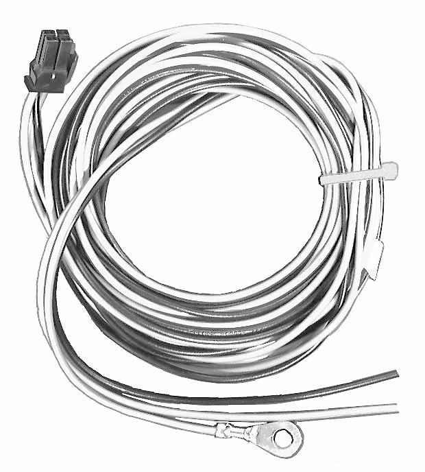
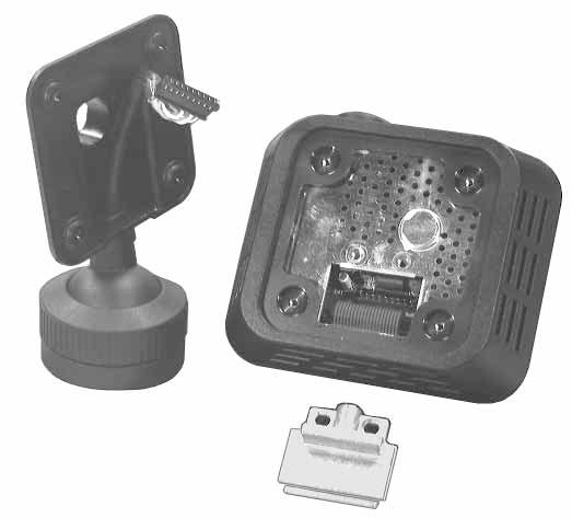
2 GB Safety instructions Installation and connection regulations While installing and mounting this equipment, you must disconnect the negative terminal of the battery. Important: You must also comply with all safety instructions given by the auto manufacturer (alarm system, vehicle immobilizer, airbag)! Before drilling holes for mounting the equipment or laying the wiring, make sure that existing wiring or auto parts (such as the petrol tank, fuel line) will be damaged. Use wire bushings on sharp-edged holes. In order to avoid any interference, lay all wiring far eugh away from the wire harnesses. Equipment fuses: Basic unit: 5 A wire fuse 5 A miniature fuse GPS receiver: 5 A wire fuse Magnetic field sensor (electronic compass) Note: You must determine the optimum mounting location for the magnetic field sensor in each vehicle individually. Before permanently installing the magnetic field sensor, attach it temporarily and then test the chosen location with the installation and calibration CD-ROM to make sure everything operates correctly. The magnetic field sensor must be installed in the passenger room. It determines the driving direction by measuring the horizontal earth magnetic field component. Since the earth magnet field is relatively small, you must ensure that there is magnetic or electromagnetic interference affecting the magnet field sensor at the chosen mounting location. Use the enclosed mounts to attach the magnet field sensor to a window which cant be opened or, especially where estate wagons or liftback cars are concerned, mount it without fasteners underneath the inside roof lining using double-sided sticky tape. Note: If the magnetic field sensor is mounted in the direct vicinity of an AM radio antenna integrated into the rear window, it may cause occasional interference in the radio reception in the long wave range. Notes on the operation of the system In order to ensure the trouble-free operation of the navigation system, a calibration must be performed after the equipment has been installed. A special installation and calibration CD-ROM, including operating instructions, is required. Software available for the Berlin RCM 303 A operating panel from version is capable of controlling the navigation componentry. Older software must be replaced by the most recent update, whereby an update for the tuner software is also required (at least version ). Note: An error message list, a service checklist and diagstic aids have been included at the end of these installation instructions. Componentry Fig. 1 The navigation componentry consists of a navigation computer with an integrated CD-ROM drive (navigation unit), a NAVI interface, a GPS receiver with an antenna, a precision resistor for the rear window defogger, a magnetic field sensor, wheel sensors, a loudspeaker and mounting material. Mounting location for the navigation unit Remove the transport block (two brass screws in the upper plate) before beginning the installation work. Keep these screws in a safe place in case the unit must be set in for servicing. After removing the screws, insert the enclosed plugs into the holes in the upper plate. The navigation unit need t be installed at any particular position. When choosing the mounting location for the navigation unit, you must make sure that the unit is installed lying in a horizontal position (you must be able to read the writing on the flap). Make sure that there is eugh room to insert the navigation CD into the CD drive. Use the enclosed installation material in order to mount the navigation unit.positive connection Fig. 2 Positive connection Fig. 2 The navigation unit must be connected to permanent plus 12 V and positive via the ignition. Lay the permanent plus 12 V wire (red) to the battery (do t lay the wiring directly by the wire harnesses). Attach the fuse carrier to protect the positive wire and connect it to the positive terminal on the battery (if necessary, drill a hole through the splashboard and use wire bushings accordingly). Connect the switching plus wire (black) with the fuse carrier at terminal 15 (switched to plus via the ignition) behind the fuse. In cars in which it is t possible to connect the wire in the fuse box, use the enclosed fuse carrier to connect the wire directly to terminal 15 at the ignition. Remove the steering wheel panelling first. Negative connection Fig. 2 Screw the negative wire (brown) directly onto the chassis. Scratch the contact point for the ground down to the bare metal and grease it with antiseize graphite petroleum (important for good grounding) Testing the mounting location of the magnetic field sensor Two different tests are required. 1. Test for permanent magnetic interference Load the installation disk. Select find compass location, and then compass ellipse and drive the vehicle in a circle. A circle should appear on the display inside the squares (ideally the circle should be in the centre). If this circle is partially or entirely outside of the squares, then you must mount the magnetic field sensor in a different place. 2. Testing for interference caused by other electrical equipment Load the installation disk, select find compass location and then compass error. Press reset, switch on the consumers (e.g. sliding sun roof, rear window wiper). The value indicated for Loc. error must be less than 3.5. Press reset each time you switch on a different piece of electrical equipment. After having tested each piece of electrical consumer individually, check logical combinations as well. The sum of the values for the consumers must t exceed a Loc. error of 3.5. If the value registered exceeds 3.5, then you must mount the magnetic field sensor in a different location. Note: Do t switch on the rear window defogger while testing for interference from the electrical equipment. Any interference caused by the rear window defogger is registered separately during calibration and then compensated. Precision resistor for the rear window defogger (shunt) The precision resistor has 2 connection wires and 1 measuring wire: 1. Connection to the ground contact of the rear window defogger (length: 250 cm), 2. Connection to the vehicle chassis (length: 75 cm), 3. Measuring wire to the navigation unit (length: 50 cm), Fig. 3 The mounting location of the precision resistor depends on the length of the wiring. Do t lengthen the connection wires for the ground contact and the vehicle chassis. Do t attach the connection for the vehicle chassis to the liftback in estate wagons or liftback cars. Select the mounting location for the precision resistor so that any heat build-up will be eliminated (chassis metal). Lay the measuring wire to the navigation unit and connect it to the corresponding jack of the compact plug, Fig. 3 Note: No other electrical equipment (e.g. rear window wiper) may be connected to the ground contact for the rear window defogger, except for the rear window defogger.
3 Wheel sensors and magnetic strips Fig. 4 Safety instructions Never screw the wheel sensor clamp onto any stress-bearing parts. Never drill holes in any stress-bearing parts. Do t attach the sensor wiring to the brake lines or to any moving parts. The wheels must be tightened using the torque recommended by the factory (approx. 100 Nm). Mount the wheel sensors and the magnetic strips on the free-rolling wheels, for four-wheel drive cars, on the rear wheels. In order to mount both the wheel sensors and the magnetic strips, the vehicle must be jacked up. Screw the wheel sensors onto the sensor mounts and look for a suitable mounting location. The sensors must t swing mechanically and they should be placed in a sheltered location. While mounting the wheel sensors, it is essential to comply with the installation tolerances, Fig. 5 Seen from the driving direction, the antenna is to be mounted on the righthand side in the rear of the vehicle (passenger s side, in Great Britain, driver s side). On tchback vehicles, mount the antenna on the lid of the boot using the corner clamps, Fig. 6. On estate wagons and liftback cars, set the antenna on the roof with its magnetic foot, Fig. 7. For a roof mount, remove the corner clamps, Fig. 8. For estate wagons and liftback cars, lay the antenna wire along the rain gutter downwards and into the interior of the vehicle, Fig. 9. Any obstacles near the antenna, such as roof or bicycle carriers, may adversely affect or even prevent satellite reception. Lay the antenna wire into the interior of the vehicle and connect the BNC plug on the antenna wire with the antenna jack on the GPS receiver. It is advisable to remove the antenna from the roof when driving through a carwash. Installation of the GPS receiver The mounting location of the GPS receiver depends on the length of the antenna cable (2.5 m) and the connection line to the navigation unit (1.5 m). Screw the GPS receiver into a dry position in the boot. Do t use screws Mounting the magnetic strips longer than 7 mm, otherwise you may destroy the GPS receiver, Fig. 10. After you have found a suitable location for the wheel sensors, you must determine the position of the magnetic strips on the inside of the wheel Loudspeaker rims. Mark the location selected for the magnetic strip and remove the Install the loudspeaker for the voice directions in the foot area of the wheel. vehicle so that it is possible to understand the voice instructions clearly. Before unscrewing the wheel nuts, mark the position of the wheel on the wheel hub. Connecting the sensors for the navigation unit Because the magnetic strips are glued into position, the rim must be free Lay the connecting wires for the precision resistor, the wheel sensors, the of rust, dirt, grease and water. Clean the inside of the wheel rim loudspeaker and the magnetic field sensor to the navigation unit and thoroughly (brake cleaning fluid, brake and clutch cleaner). connect them to the compact plugs, Fig. 11. To ensure that the glue adheres properly, the rims must be at room temperature. Display After thoroughly cleaning and perhaps allowing the rims to warm up, glue The display is mounted on a swivel base. the magnetic strips onto the marked spots over the entire area parallel to If it is t possible to mount the display on a swivel base, you may the outer edge of the rim, Fig. 4 alternately use a gooseneck. You can order the gooseneck as an Notes accessory under the order number Do t glue the magnetic strips directly onto the edge of the rim, as here The hook-up wire can be laid into the base either from the side or from they can be damaged very easily. underneath. In order to lay the wire into the base from underneath, drill a 15 mm hole where the display is to be installed and pull the plug from the display. Do t piece the magnetic strip together and cut it only at the Warning: Make sure t to damage any other wires, the airbag, etc. marked points (maximum gap between the beginning and end while drilling the hole. point, one field = 25 mm). In order to pull the plug in the display, screw it apart as follows: 1. Loosen the four screws on the back of the display and remove the Mount the wheels and tighten the nuts. Align the wheel sensors in rear plate (Fig. 12). keeping with the installation tolerances, Fig. 5, and screw them on. 2. Loosen the two screws on the strain relief inside and remove it Lay the sensor wires into the interior of the vehicle (use any existing (Fig. 13). bushings or drill new holes) and lay them to the navigation unit. 3. Remove the plug carefully and push it through the base. Push the wire through the hole where the display is to be installed, push it from underneath into the base and plug it in. Screw the display back GPS receiver together (Fig. 14). Mounting the antenna The base can also be mounted on the back of the display. Proceed as Important information: follows: - Mount the antenna on a metal roof only. It is t permissible to 1. Loosen the four screws on the back plate of the display and remove mount the antenna on synthetic roofs or aluminium. the rear plate (Fig. 12). - When mounted on a roof (held only by a magnet), the antenna 2. Loosen the two screws on the strain relief inside and remove it must t be exposed to temperatures lying outside a range of -20 (Fig. 13). C to +80 C. 3. Remove the plug carefully and push it through the base. 4. Remove the cover from the back plate of the display and remove the - It is t permissible to mount the antenna on roofs covered with retaining spring (Fig. 15). leather or synthetic material. 5. Pull the base off the back plate and insert it where the cover was - Use protective sheathing to protect the antenna wire from being located (Fig. 16). pinched. Push the retaining spring into the tch in the base, insert the cover - The adhering surface of the antenna must be free of dirt, sw, ice, where the base was located, lay the wire through the base and reassemble etc. the display (Fig. 17). In order to mount the base, unscrew it and use four screws to fix it to the - You must t lengthen, shorten or bend the antenna wire. Do t installation location (Fig 18). remove the plug during the installation. - If the antenna is painted with the same colour as the vehicle, especially paints containing a high percentage of metal, this may Modifications reserved! adversely affect the reception. There is guarantee that the antenna will operate properly after it has been painted


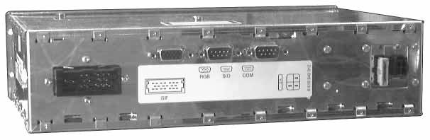

4 Componentry Fig. 1 Navigation unit Operating Panel


5 Componentry Fig. 1 GPS receiver GPS antenna Precision resistor Magnetic field sensor


6 Componentry Fig. 1 Wheel sensors (2x) Wheel sensor extension cord (2x) Display Loudspeaker


7 Mounting material Positive-negative connection Fig. 2 UBatt terminal 30 red Ignition terminal 15 black ground brown


8 Precision resistor connection Fig. 3 Connection block for the navigation unit Rear Heckscheibe window + Chassis Heckscheibe Chassis 75 cm rear window 250 cm measuring wire 50 cm precision resistor Mounting the wheel sensor and magnetic strip Fig. 4 cut edge max. 25 mm 12.7 mm rim edge magnetic strips 12.7 mm
9 Installation tolerances for the wheel sensors Fig. 5 Clearance Z: Z = 6.5 mm ± 1.5 mm Z centre of the sensor Offset Y: The centre of the sensor must be located over the entire circumference of the wheel over the magnetic strip. Y Y Set angle: The edges of the wheel sensor must be set at a distance conforming to Z. Z 5 mm Z 8 mm 10 Turning angle: The turning angle must t exceed 10. Length of the metal holder: The free-standing length must be kept as short as possible (max. 90 mm). If the free-standing length is greater than 90 mm, then the metal holder must be reinforced. 90 mm Rotation angle T: The rotation angle must t exceed 20. Special case: T = 90, do t mount the metal holder facing in the direction of the magnetic strip. T Special case 90 metal holder will affect the magnetic field


10 Fig. 6 Fig. 7 Fig. 8 loop loop Fig. 9 Fig
11 Connecting the sensors for the navigation unit, Fig Kl. 15 Kl.30 Rear window 5A +12V 12V Chassis 75 cm Rear window 250 cm + Precision resistor Wheel sensor Loudspeaker Wheel sensor Operating Panel Magnetic field sensor


12 Mounting the Display Fig. 12 Fig. 15 Fig. 13 Fig. 16 Fig. 14 Fig. 17 Fig
13 Error message list The following error messages can appear in the top line on the screen in any menu regardless of what function is currently being performed. Check r. wheel sensor, Check l. wheel sensor : No signals are being received from the wheel sensor indicated, or the signals are being interrupted sporadically. This error can only be registered while the car is in motion. Check the compass : The compass is t connected or the voltage level of the compass is outside of the valid value range. This error can only be registered while the car is in motion. Check the GPS antenna : The GPS antenna wire is faulty. This message will appear only if the GPS receiver is connected. CD reading error : Either data is being read from the CD or the CD player is making repeated transmission errors. This may be caused by damp or dirty CDs, CDs slipping in the cartridge or errors on the CD in the map data. Please insert disk : The CD has been removed while the system was in operation. If the navigation programme continues to try and retrieve data from the CD in order to load the map data or calculate a route, for example, then the error message CD reading error may appear. No voice output : Voice output is t possible because the vocabulary data is being loaded. This message will only then appear, when the user allows the acoustic driving recommendation to repeat. Service Checklist Check the following points during servicing! 1) Is the operating power supply all right? 2) Is the basic navigation unit mounted so that it is free of vibration? 3) Has the navigation CD-ROM been loaded correctly into the CD- ROM player? 4) Has the mounting location for the magnetic field sensor been selected correctly? 5) Does the customer transport metal parts frequently and are these parts in the vicinity of the magnetic field sensor? 6) Have the wheel sensors been installed on the free-rolling wheels at a distance of 5 to 8 mm from the magnetic strips? 7) Have the wheel sensors been mounted on the corner clamps so that they are free of vibration? 8) Have the magnetic strips been mounted correctly and t damaged? 9) Have the magnetic strips been glued in straight with a gap of t more than 2.5 cm? 10) Has the precision resistor been mounted correctly and its operation tested? 11) Is the GPS antenna all right, is the reception obstructed in any way? No GPS receiver connected : will appear in the DSC MENU / GPS STATUS if data is received from the GPS receiver via the serial interface. Possible causes: The wire connecting the GPS receiver and the navigation unit is t hooked up or is damaged, the power supply to the GPS receiver is faulty. No position : This message will appear in the DSC MENU / GPS STATUS without including the number of satellites, if there is information to be evaluated from the telegram from the GPS receiver directly after the system has been started. If the number of satellites appears on the screen, then the current location cant be determined because there are t eugh satellites available for locating. Language is being loaded : will appear in the DSC MENU / AUDIO MENU, when the current vocabulary data is being loaded into the speech processor. This process takes approximately 15 minutes and is done automatically when the data in the speech processor storage has been lost, for example, after an interruption in the power supply or when a different language has been selected. No crossing exists : In order to enter a location into the DSC MENU / LOCATION ENTRY, you must also enter a crossing. If a location is entered for which street names are kwn or if a street in the city is entered, but crossing is kwn, then this error message will appear. The streets cross repeatedly : When entering the location, streets have been selected which cross each other more than once, for example, because they are crescent-shaped
14 Error: Frequent loss of locating with message faulty left or right wheel sensor Load the installation disk Select wheel sensor test and drive straight on. Are the impulses for wheel 1 and 2 the same? Is the difference between the counters practically zero? Run sensor - emulator test for basic navigation unit. O.K.? Are the magnetic strips damaged? Have the magnetic strips been mounted at the correct distance (6.5 mm) to the wheel sensor? Are the magnetic strips in position properly? Have the wheel sensors been mounted properly and at the correct distance to the magnetic strips? Replace magnetic strips. No calibration required. Mount the wheel sensors properly at the correct distance (6.5 mm) to the magnetic strips. Sensor - emulator test Plug the wheel sensor into the emulator. O.K.? Replace the basic navigation unit and do a complete calibration. Replace wheel sensor. No calibration required
15 Error: Locating loss when the rear window defogger is switched on and the magnetic field sensor has been mounted on the rear window Load the installation disk. Select the hardware test wiring test. Switch on the rear window defogger. The indication for precision resistor must change by > 30 points, for example from 435 to 390 Test the basic navigation unit with the sensor - emulator test. Test passed? Check the mechanical wiring to the precision resistor. (Chassis and rear window wiring, signal wire to the basic navigation unit) O.K.? Replace the basic navigation unit and do a complete calibration. Test the signal wire to the basic unit with an ohmmeter on transition. (Resistance measures 3.3 mω) Repair wiring. Replace precision resistor and do a complete calibration on the basic navigation unit
16 Error: Regular locating loss even after a short drive Load the installation disk. Select find compass location, then select compass ellipse. Drive the vehicle in a circle. Is there an ellipse visible on the screen inside the squares? Run the sensor - emulator test on the basic navigation unit. Replace the magnetic field sensor. Repeat the compass ellipse test. Is there an ellipse visible on the screen inside the squares? Install the magnetic field sensor, lay the wiring. Do a complete calibration on the basic navigation unit. Replace the basic navigation unit and do a complete calibration. Replace the basic navigation unit and do a complete calibration
17 Error: Regular locating loss due to wheel magnetism Jack up the vehicle. Load the installation disk. Select find compass location, then select compass error. Press reset. Turn each wheel. The value indicated for Loc. error must be less than 3.5. Demagnetise the wheel and repeat the test. Error: Regular locating loss due to constant magnetic changes in the vehicle Load the installation disk. Select find compass location, then select compass ellipse. Drive the vehicle in a circle. Is there an ellipse visible on the screen inside the squares? Metal parts affect the magnetic field sensor e. g.- subsequently installed loudspeaker system - loading large metal parts into the boot - magnetic field sensor too close to vehicle chassis parts - strong magnetism surrounding the vehicle - sliding sun roof Find a new location for mounting the magnetic field sensor and do a complete calibration on the basic navigation unit
18 Error: Occasional locating loss due to electrical equipment in the vehicle Load the installation disk. Select find compass location and then select compass error. Press reset. Switch on each piece of electrical equipment individually. The value indicated for Loc. error must be less than 3.5. Check logical equipment combinations as well. The sum of the values for the equipment must t exceed a Loc. error of 3.5. Eliminate interference (if possible) e.g. relay the wiring for the car phone. Find a new location for the magnetic field sensor and do a complete calibration on the basic navigation unit. Error: CD reading error appears in the display Remove the navigation CD from the CD-ROM player. Is the NAV-CD lying correctly in the cartridge? Is the cartridge closed properly? Are there any scratches clearly visible on the data side of the NAV-CD? Insert the NAV-CD correctly into its cartridge and close it properly. Do a test drive. Replace the NAV-CD and the basic navigation unit and do a complete calibration. In the winter, moisture may sometimes condense on the laser system when it warms up after starting. After a few minutes the condensation will evaporate. The navigation system will operate properly again
19 Error: No GPS satellite reception for several days Load the installation disk. Select GPS status display. No GPS communication available will appear on the display. Connect a test GPS antenna. Find a clear area and switch the navigation system on. After approximately 1 minute GPS communication should be possible. Install the GPS antenna properly and lay the wiring. Do t calibrate the basic navigation unit. Check the connection wire from the GPS receiver to the navigation and the power supply. Replace defective wiring or fuses. Do t calibrate the basic navigation unit. Replace the GPS receiver. Wait approximately 1 minute. Install the GPS receiver properly. Do t calibrate the basic navigation unit. Replace the basic navigation unit and do a complete calibration
TravelPilot RNS 149 US
 Radio/Navigation TravelPilot RNS 149 US Installation instructions Safety information Faulty installation or servicing of this equipment may result in malfunctions in the vehicle s electronic systems. To
SCION tc Navigation System Preparation. Part Number: PT
 Preparation Part Number: PT611-21111 Kit Contents Item # Quantity Reqd. Description 1 1 Navigation System 2 1 GPS Antenna 3 1 Bluetooth Antenna 4 1 Wire Harness (Reverse / Park Brake) 5 1 RCA Relay Cable
RAV4 TNS310 (Traffic) Plus
 Plus") TNS310 (Traffic) Plus RHD installation instructions Model year: 005 Vehicle code: **A3***-*****W Part number TNS310 Plus: Sub wire harness No 1: 08673-64801 Sub wire harness No : 08673-64800 Part number
TNS310 (Traffic) Plus RHD installation instructions Model year: 005 Vehicle code: **A3***-*****W Part number TNS310 Plus: Sub wire harness No 1: 08673-64801 Sub wire harness No : 08673-64800 Part number
U L T I M A T E R A D A R / L A S E R D E F E N S E S Y S T E M
 S m a r t e r Q u i e t e r M o r e A c c u r a t e U L T I M A T E R A D A R / L A S E R D E F E N S E S Y S T E M Installation Manual PASSPORT 9500ci Comes Complete Front Radar Receiver Miniature weatherproof
TravelPilot Navigation Radio/CD. TravelPilot DX-R70. Installation instructions.
 TravelPilot Navigation Radio/CD TravelPilot DX-R70 Installation instructions http://www.blaupunkt.com Installation instructions Safety instructions When carrying out installation work and making connections
Shelbourne header monitor kit Up to 2004
 Shelbourne header monitor kit Up to 2004 The Shelboume Header Monitor monitors and displays the running speeds of the Stripping Rotor and the Auger of the combine header. The speed of either can be displayed
Corolla TNS600. RHD installation instructions. Model year: 2004 Vehicle code: **E12*R-****W
 Corolla RHD installation instructions Model year: 2004 Vehicle code: **E12*R-****W Part number: Navigation System PZ 445-00331-00 Clusterpanel 55406-02070-B0 Manual ref. no: AIM 000 767-0 PRECAUTIONS PLEASE
Navigation TravelPilot DX-N Installation instructions
 Navigation TravelPilot DX-N 7 612 001 460 Black monitor 7 612 001 461 Upgrade without monitor 7 612 001 462 Silver monitor Installation instructions Safety precautions 2 Congratulations on your purchase
Consists of. Date:17/02/2011 Page 1/8
 Consists of 470518 Qty. Product 4 1 DEFA Termina - interior heater with holder 1 1 DEFA Futura - time program controller/timer 3 1 DEFA MultiCharger 1203 - battery charger/relay 6 1 DEFA Extension cable
SCION im PREMIUM AUDIO Preparation
 SCION im 2016 - PREMIUM AU Preparation Part Number: PT296-12160 (Extension Module w/ AHA) Kit Contents Item # Quantity Reqd. Description 1 1 Extension Module 2 1 BT cable 3 1 DA/Ext Harness 4 1 GPS Antenna
Previa (RHD) - MMC PZ425-R PART NUMBER INSTALLATION INSTRUCTIONS TOYOTA NAVIGATION SYSTEM. (Production date 05/03)
 - MMC PZ425-R PART NUMBER INSTALLATION INSTRUCTIONS TOYOTA NAVIGATION SYSTEM. (Production date 05/03)") TOYOTA NAVIGATION SYSTEM Previa (RHD) - MMC INSTALLATION INSTRUCTIONS PART NUMBER NAVIGATION KIT 08545-52800 MOUNTING BRACKET FOR **R*R (Production date 05/0) PZ425-R0261-60 Manual ref. n NRR/W-0-0 TOYOTA
TOYOTA NAVIGATION SYSTEM Previa (RHD) - MMC INSTALLATION INSTRUCTIONS PART NUMBER NAVIGATION KIT 08545-52800 MOUNTING BRACKET FOR **R*R (Production date 05/0) PZ425-R0261-60 Manual ref. n NRR/W-0-0 TOYOTA
Removing and installing front windscreen
 51 31 000 Removing and installing front windscreen To bond windshield: Adhesives for cold and hot working are permitted. Remove interior rearview mirror, refer to 51 16 060. If necessary, remove rain sensor,
Installation instructions for the TriVision Car Docking Station
 Contents 1. Symbols used in this installation guide......................................... 30 2. Prior to installation......................................................... 31 3. Safety instructions.........................................................
If technical support is required, please contact Advent Technical Support at
 Document 128-9015A Created 12/12/11 Kit Contents: Item # Qty. Component Description 1 2 Headrest Assembly 2 2 Cables # 3 3 1 Power Cord # 9 4 1 FM Antenna 5 1 Control Box 6 2 IR Headphones 7 2 Remote Control
LOOKOUT LED LIGHT BAR INSTALLATION MANUAL 7900 SERIES
 LOOKOUT LED LIGHT BAR INSTALLATION MANUAL 7900 SERIES Your purchase of a Wolo warning light is the perfect choice to compliment your vehicle. Wolo s warning lights are manufactured with the finest materials.
Compact Heat Meters. Features. -A Pulsed output. -B M-Bus output. Accessories. UK Sales Tel: International Tel:
 Compact Heat Meters Features Compact design Simple operation Pulsed output Measures heating or cooling Specification Product Codes Water Meter Temp. range 10 to 90 C Nominal pressure 16bar Installation
2006 MINI Cooper ACCESSORIES & EQUIPMENT Audio, Navigation & Anti-Theft Systems - Repair Instructions - Cooper (1.6L) R50/W10 & Cooper S
 R50/W10 & Cooper S") Fig. 1: Locating Radio Receiver Retaining Screws 2006 MINI Cooper 2002-05 ACCESSORIES & EQUIPMENT Audio, Navigation & Anti-Theft Systems - Repair Instructions - Cooper (1.6L) R50/W10 & Cooper S MONO RADIO
Fig. 1: Locating Radio Receiver Retaining Screws 2006 MINI Cooper 2002-05 ACCESSORIES & EQUIPMENT Audio, Navigation & Anti-Theft Systems - Repair Instructions - Cooper (1.6L) R50/W10 & Cooper S MONO RADIO
TOYOTA im NAVIGATION UPGRADE Preparation
 Preparation Part Number: PT296-00170 PT296-12170 (Extension Module w/ AHA) Kit Contents Item # Quantity Reqd. Description 1 1 Extension Module 2 1 BT cable 3 1 DA/Ext Harness 4 1 GPS Antenna kit 5 6 Bolt
Volkswagen New Beetle Body - Exterior 64 Glass, Window regulators (Page GR-64)
") 64 Glass, Window regulators (Page GR-64) Flush bonded windows Body flange, preparing for glass installation Broken rear window, removing Cleaning off excess adhesive material Curing time Installation instructions
64 Glass, Window regulators (Page GR-64) Flush bonded windows Body flange, preparing for glass installation Broken rear window, removing Cleaning off excess adhesive material Curing time Installation instructions
Installation Instructions 1
 VOYAGER Parts Audio out 3.5 PL Expansion port GPS antenna RF antenna Harness cable & Fuses Speaker Microphone Ignition VCC Mute Swivel mount GND Installation Instructions 1 Table of contents Phone Layout...
Vehicle Rear Observation System With Integrated Parking Sensors
 Vehicle Rear Observation System With Integrated Parking Sensors Model: CAMSBAR Installation/User Manual Features: 2.5" LCD Color Display 2 Ultra Sonic Rear Obstacle Sensors On-screen Display Function Automatically
AUDIO SYSTEM 8F - 1 AUDIO SYSTEM CONTENTS
 PL AUDIO SYSTEM 8F - 1 AUDIO SYSTEM CONTENTS page GENERAL INFORMATION INTRODUCTION... 1 DESCRIPTION AND OPERATION INTERFERENCE ELIMINATION... 1 DIAGNOSIS AND TESTING ANTENNA... 3 AUDIO DIAGNOSTIC TEST
Installing instruction Power-restraining FB33 March 2005
 Installing ROLTEC restraining system for vehicles, model FB33 for ROLTEC Vision electric wheelchair Table of contents General - - - - - - - - - - - - - - - - - - - - - - - - - - page 1 Included in the
TOYOTA SEQUOIA TVIP V4 REMOTE ENGINE STARTER (RES)
") Preparation Part Number: PT398-34111 NOTE: Part number of this accessory may not be the same as the part number shown. Conflicts Do not install into vehicles without RKE system. Recommended Sequence of
Preparation Part Number: PT398-34111 NOTE: Part number of this accessory may not be the same as the part number shown. Conflicts Do not install into vehicles without RKE system. Recommended Sequence of
SCION tc PREMIUM AUDIO Preparation. Part Number: PT (Extension Module w/ AHA)
") Preparation Part Number: PT296-12160 Kit Contents Item # Quantity Reqd. Description 1 1 Extension Module 2 1 BT cable 3 1 DA/Ext Harness 4 1 GPS Antenna kit 5 6 Bolt (M5x8) 6 5 Wire tie (10 ) Hardware
Preparation Part Number: PT296-12160 Kit Contents Item # Quantity Reqd. Description 1 1 Extension Module 2 1 BT cable 3 1 DA/Ext Harness 4 1 GPS Antenna kit 5 6 Bolt (M5x8) 6 5 Wire tie (10 ) Hardware
Hiace TNS600. LHD installation instructions. Model year: 2006 Vehicle code: KLH**L-**M**W
 Hiace TNS600 LHD installation instructions Model year: 2006 Vehicle code: KLH**L-**M**W Part number: Navigationssystem PZ 445-00331-00 W2DIN Conversion Kit PZ 425-H0211-60 Manual ref. no: AIM 000 759-0
Installation instructions, accessories. Satellite radio, Sirius
 Installation instructions, accessories Instruction No 31201184 Version 1.3 5 Part. No. 31296261, 31359449 Satellite radio, Sirius IMG-246543 Volvo Car Corporation Satellite radio, Sirius- 31201184 - V1.3
Datasheet PDCSY-MW-CHM. Technical Overview. Features. Product warranty and total quality commitment. General Information.
 Datasheet Compact Heat Meters Technical Overview Heat energy is calculated by using a matched pair of high accuracy sensors to measure the difference between the forward and flow temperatures. The amount
SPEED OF LIGHT PROTECTION
 Now With ESCORT Inc. 5440 West Chester Road West Chester OH 45069 800.433.3487 www.escortradar.com SPEED OF LIGHT PROTECTION S m a r t e r Q u i e t e r M o r e A c c u r a t e 2014 ESCORT Inc. Escort,
Installation and Operation Guide. Tundra HD 2500 Power Inverter. for the. Webasto BlueCool Truck System
 Installation and Operation Guide Tundra HD 2500 Power Inverter for the Webasto BlueCool Truck System www.tundrainternational.com www.techwebasto.com BCTSP0063A Table of Contents 1. Introduction 4 1.1 Disclaimer.................................................................................
System overview. Control module "VCC EN " Copyright 2004 Volvo Car Corporation. All rights reserved.
 "VCC145637 EN 20110801" 1(26) System overview Control module The rear electronic module (REM) handles functions for: alarm (certain functions) locks (certain functions) inclination sensor module (ISM)
AVH-2330NEX AVH-2300NEX AVH-1330NEX AVH-1300NEX
 AVH-2330NEX AVH-2300NEX AVH-1330NEX AVH-1300NEX DVD RDS AV RECEIVER Installation Manual Connection Precautions Your new product and this manual Do not operate this product, any applications, or the rear
Introduction...3. System Overview...3. PDC Control Unit Sensors PDC Button Interfaces Activation of the PDC...
 meeknet.co.uk/e64 Table of Contents PARK DISTANCE CONTROL (PDC) Subject Page Introduction...............................................3 System Overview...........................................3 Components
TOYOTA CAMRY TVIP V2 (GBS WITH ADD ON)
") Preparation Part Number: 08586-3T930 Kit Contents Item # Quantity Reqd. Description 1 2 Wire Harness (One wire harness is only for RS3200+) 2 1 GBS ECU 3 1 GBS Mounting Bracket 4 1 Microphone Hardware
Preparation Part Number: 08586-3T930 Kit Contents Item # Quantity Reqd. Description 1 2 Wire Harness (One wire harness is only for RS3200+) 2 1 GBS ECU 3 1 GBS Mounting Bracket 4 1 Microphone Hardware
XM8100F/CP. Satellite Radio Antenna. antenna specialists. Patents Pending
 XM8100F/CP Satellite Radio Antenna Patents Pending antenna specialists Table of Contents Pre-Installation Considerations 3 Vehicle Mounting Locations 3 Parts List 4 Installation Tips 5 Location & Glass
WARNING WARNING WARNING. English Quick start guide CAUTION CAUTION. Installation Precautions
 English Quick start guide Symbol Identification This manual uses symbols and icons to indicate safety precautions and concerns during the installation procedure. Be sure to carefully read and understand
Introduction. Preparation to Installation. Installation of SLAMSTOP
 INSTALLATION MANUAL Introduction Table of Contents About SLAMSTOP About this Manual SLAMSTOP is an innovative door closing system intended for smooth and noiseless automatic door closing of a car. The
PowerLevel s e r i e s
 Owner s Manual Hydraulic Leveling CONTENTS Introduction Operation Control Panel Automatic Leveling Manual Leveling Retracting Jacks Remote Operation Care & Maintenance Troubleshooting Error Codes 1 2 2
Special Chemicals VDC approved cleaner. General Applicability All Scion iq models, including 10 Year Anniversary Edition.
 Preparation Part Number: PT296-00140 or PT296-00142 (Extension Box w/aha) Kit Contents Item # Quantity Req. Description 1 1 Extension Module w/bt cable 2 1 DA/Ext Harness 3 1 GPS Antenna kit 4 4 Screws
GPS-D4550. Installation And Testing Guide VEHICLE TRACKING & RECOVERY SYSTEM. Model: Quick Reference Install Guide
 Model: GPS-D550 VEHICLE TRACKING & RECOVERY SYSTEM Installation And Testing Guide Quick Reference Install Guide 1 2 3 5 6 7 8 Write the VIN (Vehicle Identification Number) on the mirror hanger/activation
DNX520VBT GPS NAVIGATION SYSTEM INSTALLATION MANUAL B /00 (EW)
") DNX520VBT GPS NAVIGATION SYSTEM INSTALLATION MANUAL B54-4771-00/00 (EW) Accessories 1 2 3 4 5 6 7...2 Installation Procedure 1. To prevent short circuits, remove the key from the ignition and disconnect
DNX520VBT GPS NAVIGATION SYSTEM INSTALLATION MANUAL B54-4771-00/00 (EW) Accessories 1 2 3 4 5 6 7...2 Installation Procedure 1. To prevent short circuits, remove the key from the ignition and disconnect
GENUINE PARTS INSTALLATION INSTRUCTIONS
 GENUINE PARTS INSTALLATION INSTRUCTIONS 1 DESCRIPTION: 2 APPLICATION: 3 PART NUMBER(S) REQUIRED FOR INSTALLATION: 4 KIT CONTENTS: Remote Engine Starter Titan MY16 999K1 W4000 Remote Engine Start Kit (150
Toyota Prius Dual Player Headrest Video ATTENTION: SECURITY COVERS ARE NO LONGER INCLUDED IN THE HEADREST KITS AS OF 01/17/2011
 Toyota Prius 2011 - Dual Player Headrest Video Part Number: 00016-47210-01; 04; 11 Code : EH5 ATTENTION: SECURITY COVERS ARE NO LONGER INCLUDED IN THE HEADREST KITS AS OF 01/17/2011 Conflicts Kit Contents
P Original Series Cargo Van Lift Mounting Instructions Fullsize Ford Van present. Preparing the Gate
 Fullsize Ford Van- 1992-present Preparing the Gate 1. Remove the mounting hardware which is banded to the liftgate. 2. Verify mounting kit (Figure 1 and Table 1). S-400-40 STRAP VAN MOUNTING EAR BENT BRACKET
TOYOTA TUNDRA TVIP V4 REMOTE ENGINE STARTER (RES)
") Preparation Part Number: 08586-OC910 Conflicts Do not install into vehicles without RKE systems. Recommended Sequence of Application Item # Accessory 1 TVIP/RES Any TVIP or RES system 2 XM Radio NOTE:
Preparation Part Number: 08586-OC910 Conflicts Do not install into vehicles without RKE systems. Recommended Sequence of Application Item # Accessory 1 TVIP/RES Any TVIP or RES system 2 XM Radio NOTE:
zelsius Installation and operating manual All that counts EnergyMetering
 EnergyMetering zelsius Installation and operating manual Electronic compact heat meter M-Bus and 2 inputs/outputs optional Coaxial measuring capsule 2" q p 0.6/1.5/2.5 m³/h All that counts General information
Installation Manual. NavMate Navigation System
 NavMate Navigation System 2 OVERVIEW The consists of the following components: MENU ENTER Controller Controller Bracket Assembly Display unit GPS Antenna Video Cable Wire Harness PLEASE VERIFY RECEIPT
Windows and mirrors ELECTRIC WINDOWS. Raise and lower. One-touch operation. Automatic window drop for door opening
 Windows and mirrors ELECTRIC WINDOWS WARNINGS Before operating power windows you should verify they are free of obstructions and ensure that children and or pets are not in the proximity of window openings.
MARINE STEERING COMPASS
 MARINE STEERING COMPASS INTRODUCTION PRE-TEST OF INSTRUMENT INSTALLATION OF SENSOR SENSOR REMOVAL INSTALLING THE DISPLAY NORMAL OPERATION CHANGING THE BACKLIGHT SETTING CHANGING THE DAMPING ASSISTED STEERI
AXi-NI1-R INSTALLATION MANUAL
 Rev. 4.0 081915 AXi-NI1-R INSTALLATION MANUAL PLEASE REVIEW THIS INSTALLATION MANUAL CAREFULLY BEFORE BEGINNING ANY WORK PLUG & PLAY WIRING HARNESS COMPATIBLE WITH AXi-RGB1 AXi-RGB2 AXi-RGB3 Tech Support:
PORTAGAUGE 4 USER MANUAL
 PORTAGAUGE 4 USER MANUAL Contents 1. Introduction and Key Features 1.1 What does the Portagauge do? 1.2 The Portagauge 4 1.21 The Portagauge 4 Unit and Measuring Screen 1.22 The Portagauge 4 Definition
TOYOTA TACOMA TVIP V5
 Preparation Part Number: PT398-35090 Kit Contents Item # Quantity Reqd. Description 1 1 Wire Harness 2 1 Security ECU 3 1 GBS ECU 4 1 Status Monitor/Microphone 5 2 Warning Labels (English) 6 2 Warning
The electro-mechanical power steering with dual pinion
 Service Training Self-study programme 317 The electro-mechanical power steering with dual pinion Design and function The electro-mechanical power steering has many advantages over the hydraulic steering
Fuse state indicator MEg72. User manual
 Fuse state indicator MEg72 User manual MEg Měřící Energetické paráty, a.s. 664 31 Česká 390 Czech Republic Fuse state indicator MEg72 User manual Fuse state indicator MEg72 INTRODUCTION The fuse state
type r remote drive for auxiliary
 type r remote drive for auxiliary KICKER MOTORs installation MANUAL OC15374 03/08/2013 Revision NEW First Edition Revision History Description 2013 Canada Metal (Pacific) Limited. All rights reserved.
IVTM Installation Manual
 Integrated Vehicle Tire Pressure Monitoring IVTM Installation Manual 2nd edition Copyright WABCO 2006 Vehicle Control Systems An American Standard Company The right of amendment is reserved Version 002/06.06(us)
* Premium Audio equipped vehicles will require additional part # DP-HD0822P audio interface NOTICE OF INTENDED INSTALLATION AND USE
 * Premium Audio equipped vehicles will require additional part # DP-HD0822P audio interface NOTICE OF INTENDED INSTALLATION AND USE THE ROSEN MULTI-MEDIA NAVIGATION SYSTEMS CONTAIN AN INTERNAL VIDEO PLAYER,
GENUINE PARTS INSTALLATION INSTRUCTIONS
 GENUINE PARTS INSTALLATION INSTRUCTIONS 1 DESCRIPTION: 2 APPLICATION: 3 PART NUMBER(S) REQUIRED FOR INSTALLATION: 4 KIT CONTENTS: Remote Engine Starter Murano 2015 ~ S grade only 999K1 C3000 (Remote Engine
650 Series Cargo Van Lift Mounting Instructions Ford Transit (Standard Roof) 2015-Present
 2015-Present") TOMMY GATE OWNER'S / OPERATOR'S MANUAL 650 Series 650 LB Capacity 650 Series Cargo Van Lift Mounting Instructions Ford Transit (Standard Roof) 2015-Present Installing the Base Plate 1. Examine the interior
TOMMY GATE OWNER'S / OPERATOR'S MANUAL 650 Series 650 LB Capacity 650 Series Cargo Van Lift Mounting Instructions Ford Transit (Standard Roof) 2015-Present Installing the Base Plate 1. Examine the interior
D40C HINGE # x Support Plate x M8 Bolt 8 x M8 Washer 6 x M6 20mm Bolts 6 x M6 Washers 19 x Screws
 HINGE # 1017 2 x Support Plate 1018 8 x M8 Bolt 8 x M8 Washer 6 x M6 20mm Bolts 6 x M6 Washers 19 x Screws 2 x Lid mount gas strut bracket 1041 2 x Self tap strut mount 1040 1 x Central Lock bracket 1510
WARNING WARNING WARNING CAUTION
 English Quick start guide Symbol Identification This manual uses symbols and icons to indicate safety precautions and concerns during the installation procedure. Be sure to carefully read and understand
Professional Séries. Professional Séries. Model T03828 SUBMERSIBLE SUMP DUPLEX SYSTEM SUBMERSIBLE SUMP DUPLEX SYSTEM. 1/3HP 2400 GPH Head of 20 (6 m)
") Model T0828 Primary pump 1/HP 200 GPH Head of 20 (6 m) SUBMERSIBLE SUMP DUPLEX SYSTEM Professional Séries Discharge: 1 1/2 ABS DWV pipe Electric cable: 9 piggyback type Oil cooled Cast iron construction
Model T0828 Primary pump 1/HP 200 GPH Head of 20 (6 m) SUBMERSIBLE SUMP DUPLEX SYSTEM Professional Séries Discharge: 1 1/2 ABS DWV pipe Electric cable: 9 piggyback type Oil cooled Cast iron construction
Installation and User Manual. with RAIN SENSOR.
 with RAIN SENSOR www.solarsmartopener.com Revision..0 TABLE OF CONTENTS Features In The Box Further Items Required Basic Operation Solar Panel and Operator Installation Operator Installation Solar Panel
CAUTION WARNING. Heading Sensor Assembly HEADING SENSOR FUNCTIONS THEORY OF OPERATION MOUNTING CONSIDERATIONS
 Heading Sensor Assembly 2996400 COMPATIBLE WITH ALL BLUETOOTH ENABLED i-pilot AND i-pilot LINK TM SYSTEMS Item / Assembly Part # Description Qty. A 2996400 HEADING SENSOR ASSEMBLY 2393400 SCREW-#8-8X-/2
Date: Order No.: Supersedes: Group: WARNING
 Installation Instructions Date: August 2005 Order No.: Supersedes: PRELIMINARY DRAFT Group: 82 SUBJECT: MODEL 171.454/456/473 MODEL YEAR 2006 SATELLITE RADIO INSTALLATION WARNING Do not disconnect the
Parts and Accessories Installation Instructions
 Parts and Accessories Installation Instructions Installation kit, sound module MINI (R5) Cooper S (R53) Left-hand drive (LHD) Not suitable for vehicles with option SA 69 (navigation system with on-board
Installation Instructions LamboStyleDoors (The instruction are to be used as a reference. Please repeat for both doors)
") Installation Instructions LamboStyleDoors (The instruction are to be used as a reference. Please repeat for both doors) Hyundai enesis Coupé type BK38 Part number 500 66 002 Pre installation check list:
Installation Instructions LamboStyleDoors (The instruction are to be used as a reference. Please repeat for both doors) Hyundai enesis Coupé type BK38 Part number 500 66 002 Pre installation check list:
Radio/Navigation. TravelPilot RNS 150. Installation instructions
 Radio/Navigation TravelPilot RNS 150 Installation instructions Installation instructions 3. Installing the antenna Connect the antenna wiring to the enclosed bracket(see Fig. 5). 3.1 Radio antenna In pre-equipped
* JBL Audio equipped vehicles will require additional part # DP-TYJBL1 audio interface NOTICE OF INTENDED INSTALLATION AND USE
 * JBL Audio equipped vehicles will require additional part # DP-TYJBL1 audio interface NOTICE OF INTENDED INSTALLATION AND USE THE ROSEN MULTI-MEDIA NAVIGATION SYSTEMS CONTAIN AN INTERNAL VIDEO PLAYER,
Onboard. Onboard RTU270 Installation Manual
 Onboard Onboard RTU270 Installation Manual Contents Parts Checklist 3 Pre-installation considerations 4 Installation 5 Status LEDs 7 Completing Installation 8 2 Onboard RTU270 Installation Parts Check
TOYOTA Yaris Hatchback EC REARVIEW MIRROR Preparation
 Preparation Part Number: PT374-02090 Kit Contents Item # Quantity Reqd. Description 1 1 Auto Dimming Mirror Assembly w/ shift area light 2 1 Hardware bag Hardware Bag Contents Item # Quantity Reqd. Description
INSTALLATION AND WIRE CONNECTION MANUAL
 INSTALLATION AND WIRE CONNECTION MANUAL 1. SAFETY PRES Symbol Identification This manual uses symbols and icons to indicate safety precautions and concerns during the installation procedure. Be sure to
SAS Fitting Kit Manual RALLY CAR
 P a g e 1 SAS Fitting Kit Manual RALLY CAR P a g e 2 Welcome This manual is provided as a guide for the installation of the WRC Tracking System Kit, for competition vehicles only. Care should be taken
ETA. Corolla Verso RHD ELECTRONIC TRAFFIC AVOIDANCE. INSTALLATION INSTRUCTIONS for ETA ANTENNA (*) MAIN KIT ETA PZ445-T ANTENNA KIT
 MAIN KIT ETA PZ445-T ANTENNA KIT") ETA ELECTRONIC TRAFFIC AVOIANCE INSTALLATION INSTRUCTIONS for Corolla Verso REQUIRE PARTS ALREAY PREWIRE ETA ANTENNA (*) NOT PREWIRE MAIN KIT ETA PZ445-T933-00 ANTENNA KIT - PZ445-T928-00 ETA BRACKET -
ETA ELECTRONIC TRAFFIC AVOIANCE INSTALLATION INSTRUCTIONS for Corolla Verso REQUIRE PARTS ALREAY PREWIRE ETA ANTENNA (*) NOT PREWIRE MAIN KIT ETA PZ445-T933-00 ANTENNA KIT - PZ445-T928-00 ETA BRACKET -
INSTALLATION INSTRUCTIONS FOR THE TOMAHAWK ELECTRIC REVERSE
 INSTALLATION INSTRUCTIONS FOR THE TOMAHAWK ELECTRIC REVERSE LAST UPDATED: April 2018 Thank you for choosing the Motor Trike Electric Reverse. We ask that you read the directions before you start and follow
Networkfleet 3500 Product Line Installation Guide
 Networkfleet 3500 Product Line Installation Guide Light/Medium Duty (L3500) Heavy Duty (H3500) Universal (U3500) www.networkcar.com/fleet Customer Care: (866) 227-7323 customercare@networkcar.com Table
Wired Real Time GPS Installation Instructions
 Wired Real Time GPS Installation Instructions This page intentionally left blank. TABLE OF CONTENTS 1. Introduction 2 2. Selecting the Mounting Location for the Device. 3 3. Mounting the Device 5 4. Optional
Attitude And Direction
 CIRRUS AIRPLANE MAINTENANCE MANUAL Attitude And Direction CHAPTER 34-20: ATTITUDE AND DIRECTION GENERAL 34-20: ATTITUDE AND DIRECTION 1. General This section contains information pertaining to those portions
For additional technical tips, please visit
 NOTICE OF INTENDED INSTALLATION AND USE THE ROSEN MULTI-MEDIA NAVIGATION SYSTEMS CONTAIN AN INTERNAL VIDEO PLAYER, WHICH IS NOT INTENDED FOR VIEWING BY THE DRIVER. THE VIDEO PLAYER IS DISABLED WHEN THE
Instruction of connection and programming of the VECTOR controller
 Instruction of connection and programming of the VECTOR controller 1. Connection of wiring 1.1.VECTOR Connection diagram Fig. 1 VECTOR Diagram of connection to the vehicle wiring. 1.2.Connection of wiring
TOYOTA VENZA HANDS FREE BLU LOGIC Preparation
 TOYOTA VENZA 2009- HANDS FREE BLU LOGIC Preparation Part #: PT923-00111 Conflicts: JBL Audio NOTE: Part number of this accessory may not be the same as the part number shown. Kit Contents: For kits manufactured
VDS102T DROP-DOWN VIDEO MONTOR
 VDS102T DROP-DOWN VIDEO MONTOR ON OFF AUTO Installation Guide Important Notice An LCD panel and/or video monitor may be installed in a motor vehicle and visible to the driver if the LCD panel or video
TOYOTA TUNDRA TVIP V4 Preparation
 Preparation Part Number: PT398-00100 PT398-00100-AA Conflicts Do not install into vehicles without RKE system. Recommended Sequence of Application Item # Accessory 1 TVIP/RES Any TVIP or RES system 2 XM
* JBL Audio equipped vehicles will require additional part # DP-TYJBL1 audio interface NOTICE OF INTENDED INSTALLATION AND USE
 * JBL Audio equipped vehicles will require additional part # DP-TYJBL1 audio interface NOTICE OF INTENDED INSTALLATION AND USE THE ROSEN MULTI-MEDIA NAVIGATION SYSTEMS CONTAIN AN INTERNAL VIDEO PLAYER,
manual magnetic linear measurement system MW10
 manual 1 Devices for operating voltage 24V DC for scanning a magnetic strip without reference point Table of contents 1 Warranty information... page 1 2 Identification... page 1 3 Mechanical mounting...
GENUINE ACCESSORIES INSTALLATION INSTRUCTIONS. ITEM QTY DESCRIPTION Usage Chart Service Part Number. 1 1 Mirror Assembly w/ Compass 1
 AUTO PART NUMBER: 0000 8C P4 (DIO)/ 0000 89 P25 (PIO) REQUIRED COMPONENTS: INSTALLATION KIT: 2 SA Harness - 2 Conductor 3 0 Wire Ties 4 Wire Cover 5 A-Pillar Tether Clip (D09W-6862) 6 3 Foam Tape 7 3 Electro-Tap(wire
SERVICE MANUAL. Hollandia 300 Large
 SERVICE MANUAL Hollandia 300 Large 1 BEFORE BEGINNING THE SERVICE PROCEDURE 1. Determine which model of the Hollandia 300 Large is installed in the vehicle. 2. Diagnose the problem by using the Trouble
AXi-MBEIRC-R INSTALLATION MANUAL
 Rev. 4.0 081915 AXi-MBEIRC-R INSTALLATION MANUAL PLEASE REVIEW THIS INSTALLATION MANUAL CAREFULLY BEFORE BEGINNING ANY WORK PLUG & PLAY WIRING HARNESS COMPATIBLE WITH AXi-RGB2 AXi-RGB3 Tech Support: 844-AXX-ESSI
INSTALLATION INSTRUCTIONS: Viewline 85 mm
 1-10 1 Safety information The product was developed, manufactured and inspected according to the basic safety requirements of EC Guidelines and state-of-the-art technology. The unit is designed for use
Challenger 60 & 70 Tow Series. Installation & User Manual
 Challenger 60 & 70 Tow Series Installation & User Manual 1 2 Contents Chapter 1 Safety & Precautions for Installers & Users...5 Safety Messages to Installers & Users Before Installation...5 Safety Messages
INSTALLING AND REMOVING THE HEATING/AIR-CONDITIONING UNIT
 INSTALLING AND REMOVING THE HEATING/AIR-CONDITIONING UNIT REMOVAL 1. Remove the covers over the heating/air-conditioning system, battery and fluid tank. Disconnect and remove the battery. 2. Remove the
2006 MINI Cooper SUSPENSION Wheels & Tires - Repair Instructions - Cooper (1.6L) R50/W10 & Cooper S
 R50/W10 & Cooper S") WHEELS 2002-05 SUSPENSION Wheels & Tires - Repair Instructions - Cooper (1.6L) R50/W10 & Cooper S 36 10 300 REMOVING OR INSTALLING FRONT OR REAR WHEEL NOTE: For Special Tool identification, see WHEEL AND
WHEELS 2002-05 SUSPENSION Wheels & Tires - Repair Instructions - Cooper (1.6L) R50/W10 & Cooper S 36 10 300 REMOVING OR INSTALLING FRONT OR REAR WHEEL NOTE: For Special Tool identification, see WHEEL AND
POWER WINDOW CONTROL SYSTEM
 POWER WINDOW CONTROL SYSTEM ONVEHICLE INSPECTION POWER WINDOW CONTROL SYSTEM 1. CHECK POWER WINDOW (MANUAL OPERATION FUNCTION) (a) Turn the ignition switch ON. (b) Check that the door glass will rise when
TOYOTA CAMRY HANDS FREE BLU LOGIC Preparation
 TOYOTA CAMRY 2008- HANDS FREE BLU LOGIC Preparation Part #: PT923-00111 Conflicts: JBL Audio, Factory Navigation NOTE: Part number of this accessory may not be the same as the part number shown. Kit Contents:
SCION iq AUDIO Preparation
 Preparation Part Number: PT546-00140 (Base Radio) Kit Contents Item # Quantity Reqd. Description 1 1 Receiver Assembly, Radio Unit 2 1 Hardware Bag Hardware Bag Contents Item # Quantity Reqd. Description
CHEVROLET TAHOE/DENALI/AVALANCHE/YUKON/ SILVERADO/SIERRA 2007+
 CHEVROLET TAHOE/DENALI/AVALANCHE/YUKON/ SILVERADO/SIERRA 2007+ INSTALLATION INTRODUCTION 1. REMOVING THE FENDER AND DOORS FROM THE A-PILLAR AND DISCONNECTING THE WIRE HARNESS @ THE DOOR JAM 2. REMOVING
REC-11+ REMOTE RECEIVER UNIT
 Resetting The Programmable Features The installer may quickly and easily return all 17 programmable features back to the factory settings. Changing individual features were explained in detail in the previous
GENUINE PARTS INSTALLATION INSTRUCTIONS
 GENUINE PARTS INSTALLATION INSTRUCTIONS DESCRIPTION: APPLICATION: PART NUMBER: DUAL DVD HEADRESTRAINT MONITOR Pathfinder - (204 Above S grade, without factory FES, and VINs ending in less than 650298)
MANUAL. Tyr MOT 250 English
 MANUAL Tyr MOT 250 English Manual for Tyr MS 250 Before bolting the machine into position, install the launching arm guard, the magazine and the launching arm. Connect the wiring. Load a small amount of
MASTERsine Inverter PXA Series Installation Guide
 Backup Power System Expert TM MASTERsine Inverter PXA Series Installation Guide Important Safety Instructions IMPORTANT: Read and save this Installation Guide for future reference. This chapter contains