FAN-PWM-V3. Instructions
|
|
|
- Tyrone Hampton
- 5 years ago
- Views:
Transcription
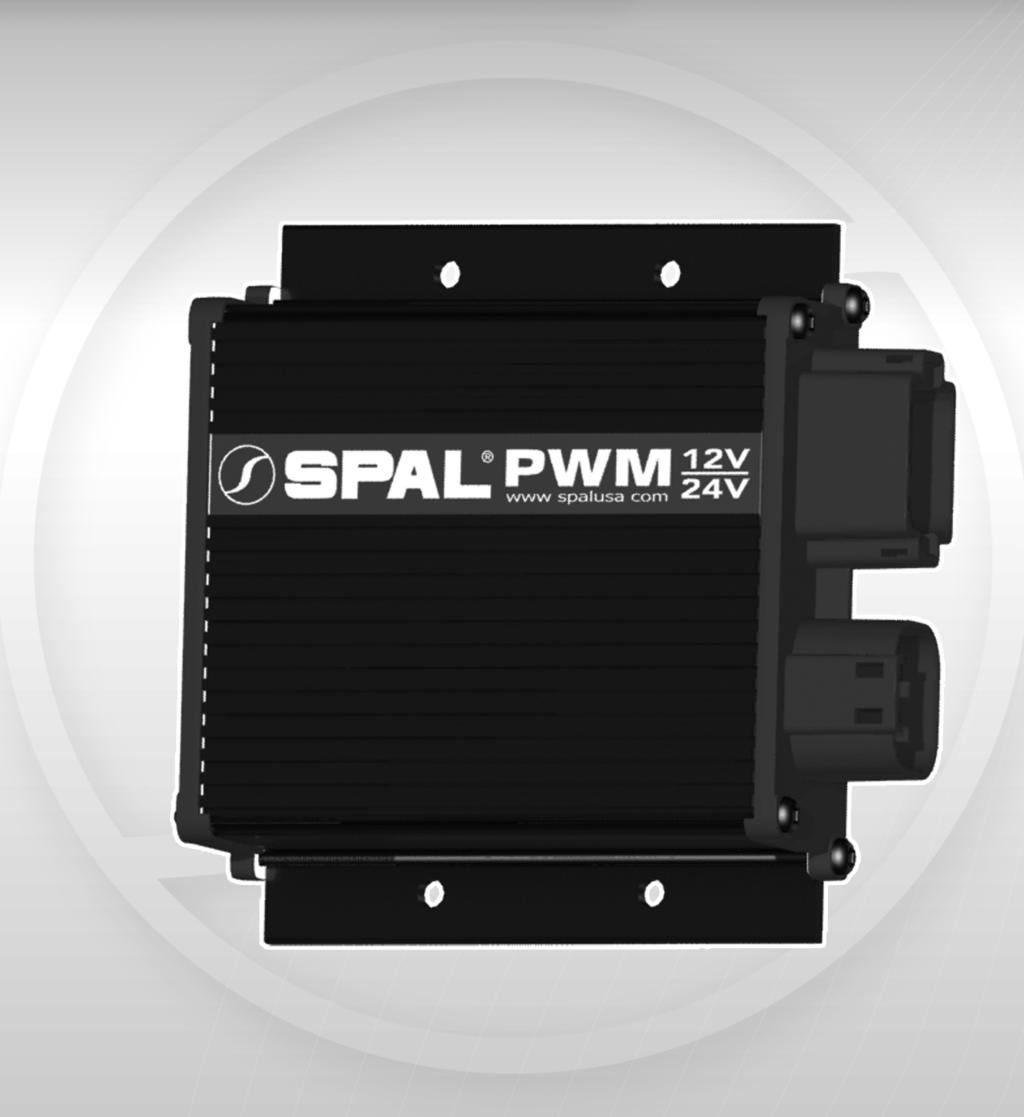
1 FAN-PWM-V3 Instructions
2 FUSE HOLDER 30 AMP FUSE BOOKLET YELLOW RING CONNECTORS (2) INSTRUCTION INSTRUCTION BOOKLETBOOKLET ITEMS INCLUDED IN KIT INSTRUCTION ITEMS INCLUDED IN KIT ITEMS INCLUDED IN KIT INSTRUCTION BOOKLET 30 AMP FUSE Parts Included ITEMS INCLUDED IN KIT In Kit FAN-PWM CONTROLLER HARDWARE BAG BCU+ BCU+ 30 BCU AMP FUSE 20 AMP YELLOW RING CONNECTORS (2) FUSE FAN-PWM CONTROLLER 20 AMP FUSE FUSE HOLDER BLUE RING CONNECTORS Hardware Bag (2) FUSE HOLDER HARDWARE BAG HARDWARE BAG FUSE HOLDER 30 AMP FUSE HARDWARE 20 AMPBLUE FUSERING HARDWARE BAG BAG CONNECTORS YELLOW RING30CONNECTORS AMP FUSE (2) (2) YELLOW BUTT CONNECTOR 20 Amp Fuse (1) 30 Amp Fuse (1) (1) 20 AMP YELLOW RING CONNECTORS (2)FUSE FAN-PWM CONTROLLER 20 FAN-PWM CONTROLLER BCU+ 30 BCU+ OPTIONAL ITEMS S AMP FUSE 20 YELLOW RING CONNECTORS 20 AMP (2) FUSE 20 AMP FUSE FUSE HOLDER 30 AMP FUSE BUTT CONNECTOR YELLOW Yellow 30 AMP FUSE Ring Connectors (2) BLUE RING FUSECONNECTORS HOLDER (1) 30 AMP FUSE (2) SELF TAPPING SCREWS MAIN HARNESS 30 AMP FUSE FAN-PWM-V3 Controller (1) MAIN HARNESS (4) BLUE RING CONNECTORS 30 AMP FUSE (2) FUSE HOLDER MAIN HARNESS FUSEBlue HOLDERRing Connectors (2) Fuse Holder (1) CONNECTORS BLUE RING CONNECTORS FRH YELLOW RING (2) MAIN HARNESS (2) FUSE HOLDER FUSE HOLDER YELLOW RING CONNECTORS (2) YELLOW BUTT CONNECTOR SELF TAPPING SCREWS FUSE HOLDER (4)YELLOW RING CONNECTORS (2) (1) YELLOW RING CONNECTORS (2) a Yellow Butt DT06-3S DT06-3S DT06-3S B RE BAG 30 Self Tapping 0 C DT06-3S B CC C BB YELLOW BUTTYELLOW CONNECTOR RING CONNECTORS (2) Connector Screws (4) (1) (1) ZIP TIES YELLOW RING CONNECTORS (2) YELLOW BUTT CONNECTOR BLUE RINGCONNECTORS CONNECTORS BLUE RING YELLOW RING CONNECTORS (2) (12) (2) CONNECTORS (1) BLUE RING(2) Main HarnessBLUE (1) RING CONNECTORS Zip (2) Ties (12) SPAL TEMP SENSOR HARNESS (2) SCREWS SPAL TEMP SENSOR HARNESSSELF TAPPING BLUE RING CONNECTORS (2) (4) SPAL TEMP SENSOR HARNESS Equipment YELLOW BUTT CONNECTOR BLUE RING CONNECTORS ZIP TIES Optional (1)CONNECTOR YELLOW BUTT (2) (1) (12)SELF TAPPING SCREWS SPAL TEMP SENSOR HARNESS (4) YELLOW BUTT CONNECTOR SPAL Temp Sensor Harness (1) BLUE RING CONNECTORS (1) CONNECTOR YELLOWSCREWS BUTT SELF TAPPING OEM TEMP SENSOR HARNESS (1) SCREWS (4) SELF TAPPING (2) YELLOW BUTT CONNECTOR OEM TEMP SENSOR HARNESS YELLOW BUTT CONNECTOR (4) SCREWS (1) SELF TAPPING (1) (4) A B AA BB A B RNESS A B 30 NESS 30 87a WARE BAG ARNESS OPTIONAL ITEMS C DT06-3S B BCU+ OEM TEMP SENSOR HARNESS ZIP TIES (12) OEMOEM Temp Sensor Harness (1) TEMP SENSOR HARNESS POWER HARNESS POWER HARNESS POWER HARNESS 20 SELF TAPPING SCREWS SPAL SENSOR (4) FRH SELF TAPPING SCREWS SPAL Sensor YELLOW BUTT CONNECTOR ZIP TIES SELF TAPPING SCREWS (4) ZIP TIES ZIP(12) TIES (1) (4) (12) SELF TAPPING SCREWS (12) (4) ZIP TIES FRHZIP(12)TIES (12) (Fan Relay Harness) Power Harness (1) POWER HARNESS 1 30 SELF TAPPING SCREWS (4) ZIP TIES ZIP TIES (12)
3 Suggested Fuse Values PULLER # PUSHER # DESCRIPTION RECOMMEDNED FUSE High Performance Fan / Paddle Blade Fan High Performance / Paddle Blade Fan Dual High Performance Fan / Pull 30/Per Motor High Performance Fan / Paddle Blade Medium Profile Fan Fan High Performance Dual Fan / Curved Paddle 30/Per Motor High Performance Fan / Curved Blade High Performance Fan / Paddle Blade Medium Profile Fan Fan High Performance Fan / Curved Blade Medium Profile Fan Fan High Performance Fan / Striaght Blade High Performance Fan / Curved Blade Medium Profile Fan Fan Extreme Performance Fan / Pull High Performance Fan / Straight Blade High Performance Fan / Paddle Blade High Performance Fan / Curved Blade Medium Profile Fan Fan
4 New Features of 3rd Generation PWM Ability to reset to any one of 3 preset temperature ranges when using FAN-PWM-TS sensor Smart fan diagnostics detects stalled or over current fans to prevent module damage New 16 bit MCU for increased resolution on temperature sensor input Primary fan low power starts to reduce the current spike on electrical system Onboard status LED and status output for vehicle interior status light Quality Deutsch IPD connectors on the premium harness made in USA Silicone rubber button membrane and case seals for improved durability Improved AC input timing to minimize fan operation during defrost cycles Single unit capable of use with both 12VDC and 24VDC systems **WHY THIS MAY BE IMPORTANT FOR YOU** In an effort to add features and improve quality of the FAN-PWM the functionality of the unit may impede previous creative installations of FAN-PWM s. A brushed DC motor MUST be connected to the fan output or the unit will report an error code. Possible use with very low power (<4A) fans and non SPAL products may also cause fan not found error code. SPAL USA will not guaranty this products functionality with NON SPAL fans as too often specifications are unknown. Over current protection means that the output will SHUT DOWN if the measured fan continuous run current increases above 30A for extended periods. If running a fan approaching this amount of current draw (>25A), SPAL USA recommends that the installation also include a status light so the operator will be aware of fan status. See page 8 for status light wiring. Because of timing sequences on the AC input wire when using a manual override switch there will be a delay before the fan turns on/off with the switch. 3
5 Introduction / Overview Congratulations on your purchase of the SPAL FAN-PWM! Due to the various installation configurations, please carefully read the entire manual before installing the FAN-PWM. This SPAL Electric Fan Controller (FAN-PWM) will vary the speed of the fan based on engine temperature by using Pulse Width Modulation technology. A second fan can be added but requires the use of an additional relay to control the secondary fan (SPAL part number FRH). The secondary fan will not be variable speed; it will be ON/OFF only. Because the FAN-PWM was designed to alter the speed of the fan, SPAL USA suggests setting the High 10 to 20 above the thermostat rating and setting the Low at least 10 below the High. Instruction Manual Highlights Wiring Programming Trouble Shooting Frequently Asked Questions (FAQ)
6 Operation ENTR PRG STAT FAN Front View of PWM The FAN-PWM is equipped with 2 LED s: a STAT LED and a FAN LED. STAT LED will be lit when the unit is powered on, system checks are OK, and the fans are not running. The 3 color FAN LED indicates when the fan output is active, and is also used during programming. Each color represents the following: AMBER for temperatures above LOW, RED for temperatures above HIGH, and GREEN when the A/C input has been activated. When the Low temperature setting is reached, the FAN LED will light AMBER, and the fan will run at 50% or ½ speed. The fan will then gradually increase in speed as the engine temperature rises. If the high temperature setting is reached, the FAN LED will light RED, and the fan will now be running at full speed. (continued next page) 5
7 Operation (continued) When the FAN LED lights RED, a negative output will be sent on the gray wire. This gray wire can be used to trigger a fan relay, an indicator light, etc. If you are using dual fans with the recommended wiring setup (refer to pages 18/19) your 2nd fan will turn on full speed at this time. If the cooling system is able to lower the coolant temperature approximately 5 below the High setting, the FAN LED will turn from RED to AMBER and the fan will slow in speed; at this time the second fan output will stop as well. If the cooling system is able to continue to lower the coolant temperature to approximately 5 degrees below the low setting, the FAN LED will turn off, the STAT LED will light GREEN, and the fan will stop completely. Mounting The SPAL FAN-PWM is water resistant and can be mounted in the engine bay or inside the vehicle. Keep the controller away from high heat sources such as the engine exhaust. Above the wheel well, on the radiator support, or firewall are good examples of proper locations. 6
8 Temperature Sensor Connection Note: Both large and small gauge ground wires must be grounded. Single Fan: Please see SINGLE FAN WIRING instructions on Page 16 and 17. Dual Fan: A dual fan set-up requires a Fan Relay Harness (SPAL part number FRH) to power the secondary fan. Please see DUAL FAN WIRING instructions on Page 18 and 19 Connecting To A Factory OEM Temperature Sensor The FAN-PWM can be used with most vehicle s original temperature sensor circuits and aftermarket electric temp gauges. This eliminates the need for an additional sensor. Some older cars sensors (as those circa the 1970 s) may not work. If you experience problems, please call our technical support line for assistance ) Vehicles With known issues: Ford modular engine s coolant/head temp (4.6/5.4L) range ~200 degrees GM Duramax (could be other new GM also) multi range ~160 degrees With these sensors the same voltage will exist at multiple temperatures. If you set the controller above the switching point of the sensor range it will technically work. The problem is that the fan will turn on at cold startup initially, turn off, before coming on again at the proper temperature. Please see the PROGRAMMING section on pages If using this type of sensor, the SPAL FAN-PWM must be programmed to your desired temperature points as the default settings will not be properly calibrated. 7
9 Temperature Sensor Connection SPAL Temperature Sensor (FAN-PWM-TS) If your vehicle is not equipped with an OEM temperature sensor, you can purchase a SPAL temperature sensor (SPAL part number FAN-PWM-TS) that plugs directly into the fan controller harness. This sensor should be located in the engine for optimal performance. When using the SPAL temperature sensor, the fan controller has a factory preset with a Low setting of ~190 and High setting of ~205. If different settings are required, please see the PROGRAMMING section on pages Optional Status Output The FAN-PWM provides a negative output for an external device such as a LED (not provided) to be used to remotely show the status of the system. With the vehicle s ignition on, the status output will indicate the following: No output: All checks OK, fan not running Output on: Fan output is active (fan could be running low to high speed) Blinking output: Indicates an error code; watch STAT LED on module for error code (See page 21) STATUS LIGHT/LED 12V - STATUS OUTPUT (BROWN) + 12VDC IGNITION POWER 8
10 Air Conditioning Input The FAN-PWM has a built in 15 second delay for ON and a 30 second delay for OFF with the Air Conditioning Input. After the A/C compressor has turned ON, the fan will not go to HIGH until after a 15 second delay. After the A/C turns off, the fan will stay on HIGH for 30 seconds before resuming normal operation. 1. If your A/C system does not have a trinary switch, connect the Blue wire directly to the +12V wire of the air conditioning compressor or a wire within your HVAC system that is powered only when the A/C is engaged. As a result any time the compressor is engaged and or the A/C is activated, the fan(s) will run at 100% with FAN LED lit GREEN. GROUND AIR CONDITIONING INPUT (BLUE) +12VDC WHEN A/C ON AIR CONDITIONING COMPRESSOR 9
11 Air Conditioning Input (continued) 2. If your A/C system has a trinary switch, you may use it to trigger your cooling fans. This is the preferred way to control your cooling fans as the fan operation is based on the pressure of the coolant in the A/C system. Though the A/C pump may not be running, the pressure of the A/C system may require operation of the cooling fans to properly cool the A/C condenser. AIR CONDITIONING COMPRESSOR A/C Thermosta t Existing wire(s) from evaporator wiring harness 5A FUSE +12VDC Blue Wire from FAN-PWM B AT TE Ground R Y 10
12 Programming ENTR PRG STAT FAN Stat LED (Green): On when FAN-PWM is powered from the ignition input. Fan(s) are not on. Blinking indicates an error code. See page 21 for error codes. 3 Color Fan LED: RED: High temperature setting has been reached. Fan(s) run at High speed. AMBER: Low temperature setting has been reached. Fan starts at half-speed and increases until High temperature setting is reached. GREEN: Indicates Air Conditioning has been powered ON. Fan(s) run at full speed. 11
13 Programming (continued) When programming the FAN-PWM the fan will turn off automatically to allow quicker warm-up of coolant temperature. If at anytime you enter programming mode by mistake, repeatedly press the PRG button until the unit returns to normal status. Setting Both The Low & High Temperature 1. Press and Hold down PRG button for 5 seconds. 2. Fan will stop running and the FAN LED will be slowly blinking AMBER. 3. Warm engine up to desired LOW temperature and press ENTR button to program LOW. 4. The STAT LED will blink once and the FAN LED will turn RED and be blinking slowly. 5. Warm engine up to desired HIGH temperature and press ENTR button to set HIGH. 6. The STAT LED will blink once then FAN LED will turn GREEN and be blinking slowly. 7. Press the PRG button once to EXIT programming. 12
14 Programming (continued) Setting The Low Temperature Only 1. Press and Hold down PRG button for 5 seconds. 2. Fan will stop running and the FAN LED will be slowly blinking AMBER. 3. Warm engine up to desired LOW temperature and press ENTR to set LOW. 4. The STAT LED will blink once and the FAN LED will turn RED and be blinking slowly. 5. Press PRG button 2 times to EXIT programming. Setting The High Temperature Only: 1. Press and Hold down PRG button for 5 seconds. 2. Fan will stop running and FAN LED will be slowly blinking AMBER. 3. Press PRG button once. 4. FAN LED will be slowly blinking RED. 5. Warm engine up to desired HIGH temperature and press ENTR button to set HIGH. 6. The STAT LED will blink once then the FAN LED will be slowly blinking GREEN. 7. Press PRG button once to EXIT programming. 13
15 Programming (continued) The FAN-PWM has 3 default programs for use with the SPAL temperature sensor (FAN-PWM-TS). Preset 1 has a LOW temp of 170 and a HIGH temp of 185. Preset 2 has a LOW temp of 190 and a HIGH temp of 205. Preset 3 has a LOW temp of 205 and a HIGH temp of 220. Selecting The Desired Preset 1. Hold down PRG button for 5 seconds. 2. FAN will stop running and FAN LED will be slowly blinking AMBER. 3. Press PRG button 2 times. 4. FAN LED will slowly blink GREEN. 5. Press ENTR button once for Preset 1. STAT LED will flash once. Press ENTR button again for Preset 2. STAT LED will flash twice. Press ENTR button again for Preset 3. STAT LED will flash three times. 6. Once desired preset has been reached Press PRG button to exit programming mode. 14
16 Wiring Wire Color Harness Wire Connection RED FAN/PWR Fan Positive with Fan Connector to Primary Fan WHITE FAN/PWR Fan Negative with Fan Connector to Primary Fan RED FAN/PWR +12VDC Power Directly to Battery BLACK FAN/PWR Ground PURPLE MAIN Not Used ORANGE MAIN Switched Ignition (+12VDC when vehicle is running) GRAY MAIN Secondary Fan Output (negative trigger for relay) BLUE MAIN Air Conditioning Input (+12VDC when A/C compressor is ON BROWN MAIN Status Output (negative output for Light/LED) WHITE OEM SENSOR OEM Temperature Sensor (Variable Voltage 0-5 HARNESS VDC) BLACK SPAL SENSOR SPAL Temperature Sensor with connector HARNESS GREEN SPAL SENSOR SPAL Temperature Sensor with connector HARNESS Optional Second Fan Relay (FRH) YELLOW FRH +12VDC Directly to Battery RED FRH Secondary Fan Positive GRAY FRH PWM Secondary Fan Output (Gray wire from FAN-PWM) ORANGE FRH Switched Ignition (+12VDC when vehicle is running) BLACK FRH Chassis Ground 15
17 Wiring (continued) Single Fan OEM Sensor OEM TEMP SENSOR (WHITE) C B GROUND GROUND (BLACK) VARIABLE VOLTAGE + STATUS OUTPUT (BROWN) SEE PAGE 8 AIR CONDITIONING INPUT (BLUE) SEE PAGE 9 MAIN HARNESS SWITCHED IGNITION (ORANGE) (GRAY) NOT USED (PURPLE) NOT USED FAN/PWR HARNESS +12VDC (RED) MAX. 30 AMP FUSE FUSE GROUND (BLACK) B AT T E R Y 16
18 Wiring (continued) Single Fan SPAL Sensor SPAL TEMP SENSOR HARNESS C B SPAL SENSOR GROUND (BLACK) STATUS OUTPUT (BROWN) SEE PAGE 8 AIR CONDITIONING INPUT (BLUE) SEE PAGE 9 MAIN HARNESS SWITCHED IGNITION (ORANGE) (GRAY) NOT USED (PURPLE) NOT USED FAN/PWR HARNESS +12VDC (RED) MAX. 30 AMP FUSE FUSE GROUND (BLACK) B AT T E R Y 17
19 a Wiring (continued) Dual Fan OEM Sensor C B GROUND (BLACK) OEM TEMP SENSOR (WHITE) STATUS OUTPUT (BROWN) SEE PAGE 8 GROUND VARIABLE VOLTAGE + NOT USED (PURPLE) AIR CONDITIONING INPUT (BLUE) SEE PAGE 9 MAIN HARNESS SWITCHED IGNITION (ORANGE) SECONDARY FAN OUTPUT (GRAY) 2ND FAN RELAY PART # (FRH) GROUND (BLACK) B AT T E R Y MAX. 30 AMP FUSE FUSE GROUND FAN/PWR HARNESS +12VDC (RED) FAN POSITIVE (RED) SWITCHED IGNITION (ORANGE) FUSE +12VDC (YELLOW) MAX. 30 AMP FUSE FAN HARNESS 18
20 a Wiring (continued) Dual Fan SPAL Sensor SPAL TEMP SENSOR HARNESS C B GROUND (BLACK) STATUS OUTPUT (BROWN) SEE PAGE 8 SPAL SENSOR NOT USED (PURPLE) AIR CONDITIONING INPUT (BLUE) SEE PAGE 9 MAIN HARNESS SWITCHED IGNITION (ORANGE) SECONDARY FAN OUTPUT (GRAY) 2ND FAN RELAY PART # (FRH) GROUND (BLACK) B AT T E R Y MAX. 30 AMP FUSE FUSE GROUND FAN/PWR HARNESS +12VDC (RED) FAN POSITIVE (RED) SWITCHED IGNITION (ORANGE) FUSE MAX. 30 AMP FUSE +12VDC (YELLOW) FAN HARNESS 19
21 Manual Fan Override Switch This will allow your cooling fan to run anytime the override switch is ON. WARNING: There is a 15 second delay after you flip the switch ON and a 30 second delay after you flip the switch OFF. After you turn the switch ON the FAN(s) will go to Full speed after the 15 second delay. The FAN(s) will stay on high until the 30 second delay is complete. If the switch is turned ON and OFF repeatedly the delay will restart after the last time the switch was turned ON or OFF. **SPAL USA suggests this override switch also trigger the electric water pump relay. This will allow a single override switch to control both the fan and electric water pump.** Note: 1. The fan will continue to run indefinitely if the switch is not shut off. 2. When running for extended periods of time, the voltage should be monitored as to not overly discharge the vehicle s battery. BLUE A/C INPUT WIRE +12VDC TO BATTERY +12VDC B AT T E R Y 20
22 Troubleshooting Resetting Or Restoring FAN-PWM Back To Factory Defaults To reset or restore the FAN-PWM back to its original settings, press and hold both the ENTR and PRG buttons down for 10 seconds. The STAT LED will blink 5 times Blinking LED Code Explanations Number of Blinks on Stat LED Error Description Code 1: Code 2: Code 3: Code 4: CODE 1: Sensor Input Not Found The FAN-PWM is not sensing a connection to a temperature sensor. Verify connections to the temperature sensor. If using an OEM sensor, verify correct temperature sensor wire is being tapped. See info under High and Low Program Data Error for more information on sensor issues. If using SPAL sensor did you cut the sensor harness connector off? If the sensor connector is cut off then you have to splice the white wire to the green wire. If you have hooked the system to a switch instead of a gauge type sender this error will occur once the switch reaches its activation temp. Primary and secondary fan will run during this error condition. 21
23 Troubleshooting (continued) CODE 2: Fan Not Found Or Fan Speed Error The FAN-PWM is not sensing a fan or the fan is not functioning properly. Verify the connections and operation. A brushed DC motor MUST be connected to the fan output or the unit will report an error code. Possible use with very low power (<4A) fans and non SPAL products may also cause Fan Not Found Error code. SPAL USA will not guarantee this product s functionality with non SPAL fans as too often specifications are unknown. CODE 3: High & Low Program Data Error You will need to reprogram the High and Low temperature settings on the FAN- PWM. If you are using the SPAL temperature sensor then you can reprogram using one of the default settings. Temperature sensor issues are addressed as follows. 1. Using a SPAL Temperature Sensor (FAN-PWM-TS) a. Your LOW and HIGH settings are too close in temperature, either move your LOW lower or the HIGH higher. A MINIMUM of 10 AT THE SENSOR between the two points is recommended. b. Possible bad wire connection. Double check all connections and repeat the programming sequence. (continued next page) 22
24 Troubleshooting (continued) CODE 3: High & Low Program Data Error (continued) 2. Using Factory Coolant Temperature Sensor (OEM) or Electric Water Temperature Gauge a. Sensor profile not compatible with current LOW/HIGH values. Depending on the application a minimum spread of 10 to 15 may not be sufficient. This is more prevalent with older factory water temperature gauges. The voltage difference between the HIGH and LOW temperature settings must be.1 Volt or higher. b. White wire not connected to proper wire on vehicle. Typically on a 2 wire coolant temp sensor, one wire will be a chassis ground while the other will vary in voltage with temperature. The white wire must be connected to the wire which varies in voltage. c. Connection was made to a temperature SWITCH not a sensor. The FAN-PWM will not function connected to a switch (such as our 185-TS) that is used to turn on a relay or warning light. The sensor type must be for a gauge or a coolant temp sensor for a fuel injection computer. d. Wiring from the sensor to the gauge or computer is faulty. The white wire is a passive input and it must be connected in parallel with the original circuitry designed for that specific sensor. 23
25 Troubleshooting (continued) CODE 3: High & Low Program Data Error (continued) e. There are some 2 stage computer sensors which vary in voltage in 2 steps. These sensors drop in voltage until they reach a certain temperature (example 200 ) then the engine raises the power level suddenly to have another similar drop in voltage. You might be able to program the FAN-PWM to work within ONE of these stages. But as a side effect, it will work also in the other stage which means the fan may operate when not necessarily needed. For complete proper operation in this case you will need to use a SPAL temperature sensor. CODE 4: Module Over Current Error Over current protection means that the output will SHUT DOWN if the measured fan continuous run current increases above 30A for extended periods. If running a fan that is approaching this amount of current draw (>25A), SPAL USA recommends that the installation also include a status light so the operator will be aware of the fan status. 24
26 FAQ My Temperature Settings Are Not Staying Programmed. After programming the Low and High temperature settings make sure you are not pressing the ENTR button when FAN LED is Blinking GREEN. If the ENTR button is pressed after programming, the FAN-PWM is set to a factory default setting erasing your previous settings. My Fan Stays On All The Time 1. DO NOT ground the primary fan to the chassis. If the fan s negative on the first fan is wired to a chassis ground, then the fan will be on. Wire the primary fan s negative to the FAN-PWM fan negative. The FAN-PWM variable speed control is through the negative side. 2. Is the A/C override hooked up? Check the power input to the Blue wire and verify that it is only receiving a + 12 VDC when the A/C is on. 3. Is the small black wired hooked to a good ground source? If there is no ground on that wire the PWM will run on high speed with the red LED on 5 seconds after the ignition is switched on. FAN-PWM Dosen t Turn On 1. Check fuses 2. Check battery and ignition wires for power 3. Check both ground connections. Make sure the small and large gauge black wires are connected to ground 25
27 1. Check relay wiring FAQ (continued) Second Fan Will Not Turn On 2. Confirm ground signal from FAN-PWM on Gray wire when on High 3. Verify fan is working properly by grounding the gray wire from the relay and turning the ignition on, fan should run at this time. Fan Does Not Go Into High Mode Immediately After The A/C or Manual Override Is Turned On 1. After the A/C or manual switch is turned on, there is a 15 second delay before the FAN-PWM will override into High Mode. 2. Verify there is + 12 Volts going to the Blue wire when A/C or switch is turned on. Fans Stays In High Mode After Turning Off The A/C Or Switch 1. After the A/C or switch is turned off, there is a 30 second delay before the FAN-PWM will resume its normal variable speed operation. 2. Verify there is no power present on the Blue wire when the A/C or switch is turned off. For optional wiring diagrams, including 2-speed fans - visit or contact tech support at tech@spalusa.com 26
28 Pin Diagram & Table FAN / PWR Harness CIRCUIT Red Fan (+) Positive To Fan Connector PIN NUMBER 1 White Fan (-) Negative To Fan Connector 2 Black Ground 3 Red +12V Constant Power From Battery
29 Pin Diagram & Table (continued) Main Harness CIRCUIT Green SPAL PWM Sensor (+) White OEM Sensor Input Brown Status Output (-) Negative Output For Light PIN NUMBER Orange Switched Ignition (+12V Only When Vehicle Is Running) 4 Black Ground Blue A/C Input (+12V When A/C Compressor Is On) 5 6 Gray Secondary Fan Output (-) Negative Trigger For Relay 7 Purple Not Used
30 Connection 29
31 Notes 30
32 SPAL Limited Warranty SPAL USA warrants this product to be free from defects in material and workmanship for a period of eighteen (18) months from the date of sale of the original purchaser. SPAL USA will repair this product free of charge if, in the judgment of SPAL USA it has been proven defective within the warranty period. The product should be returned, at the customer expense, to the location of original purchase. This warranty does not cover any expenses incurred in the removal and/or reinstallation of the product. This warranty does not apply to any product damaged by improper installation, misuse, abuse, improper line voltage, fire, flood, lightning, or other acts of God, or a product altered or repaired by anyone other than SPAL USA. This warranty is in lieu of other warranties, expressed or implied, including any implied warranty of merchantability. No person is authorized to assume for SPAL USA any other liability concerning the sale of this product. *IMPORTANT - KEEP YOUR RECEIPT WITH THIS WARRANTY STATEMENT! If you have other questions about the installation of the FAN-PWM contact SPAL USA tech support at or tech@spalusa.com. Additional information and updates can be found on at _ FanPWM1s
33
Dual Linear Actuator Controller
 Creative Werks Inc. LIMITED WARRANTY STATEMENT Creative Werks Inc. warrants this product to be free from defects in material and workmanship for a period of one (1) year from the date of sale to the original
COMMANDO REMOTE CONTROL ENGINE STARTER. Limited Warranty Statement MADE IN THE U.S.A. IMPORTANT KEEP YOUR INVOICE WITH THIS WARRANTY STATEMENT!
 Limited Warranty Statement GNU COMMANDO LINE WARRANTY STATEMENT GNU warrants this product to be free from defects in material and workmanship for a period of one (1) year from the date of sale to the original
SHAVED-40 LIMITED WARRANTY STATEMENT SPAL USA WARRANTY STATEMENT INSTALLATION MANUAL & OPERATION INSTRUCTIONS
 LIMITED WARRANT STATEMENT SPAL USA WARRANT STATEMENT Our most popular kit comes complete with (1) seven-channel receiver, () remote transmitters and () solenoids with 0 pounds of pull each. This kit also
SHAVED-DX. Installation Manual & Operation Instructions. Trouble Shooting Reverse Polarity Wiring Problems
 Trouble Shooting Reverse Polarity Wiring Problems Switch doesn't work properly but the shaved kit transmitters do work Step 1 Did you purchase a switch kit designed for three switches and only use two
SHAVED-40 INSTALLATION MANUAL & OPERATION INSTRUCTIONS
 Limited Warranty Statement SPAL USA Warranty Statement Our most popular kit comes complete with (1) seven-channel receiver, (2) remote transmitters and (2) solenoids with 0 pounds of pull each. This kit
30140 F5 Dual Fan Controller
 30140 F5 Dual Fan Controller 1 2501 Ludelle Street Fort Worth, Texas 76105 817-244-6212 Phone 817-244-4024 Fax 888-350-6588 Sales 800-423-9696 Tech E-mail: painless@painlessperformance.com Web: www.painlessperformance.com
DUAL LINEAR MOTOR / ACTUATOR CONTROLLER W/ CURRENT SENSING AUTO REVERSE
 PAC-3200 DUAL LINEAR MOTOR / ACTUATOR CONTROLLER W/ CURRENT SENSING AUTO REVERSE PAC-3200 PRESET BUTTONS MOTOR 2 DUAL LINEAR MOTOR CONTROLLER WITH SAFETY REVERSE MOTOR 2 MOTOR 1 MAIN #1 ACC DISABLE #2
NEXUS. Introduction SENSOR MODULE &
 2650-1056 INSTALLA AT TION INSTRUCTIONS NEXUS SENSOR MODULE & REMOTE ASSEMBLY IMPORTANT WEAR SAFETY GLASSES 60 80 40 100 FUEL 20 PSI 0 AUTO METER PRODUCTS INC. c 2004-6463 0 10 20 10 20 BOOST VAC In.Hg
MODEL MCL-3212 SPEEDOMETER/TACHOMETER for 2012 up Dyna and Softail with 4 gauge
 MODEL MCL-3212 SPEEDOMETER/TACHOMETER for 2012 up Dyna and Softail with 4 gauge IMPORTANT NOTE! This gauge has an odometer preset option that is only available one time in the first 100 miles (160km) of
UNIVERSAL GAUGE WIRE HARNESS
 2650-1797-00 UNIVERSAL GAUGE WIRE HARNESS For Installing Auto Meter Electric Speedometer, Tachometer, And Short Sweep Electric Oil Pressure, Water Temperature, Fuel Level, and Volt Meter Gauges. This harness
CMD-4000 SERIES REV. A 4+ FUNCTION REMOTE CONTROL DOOR LATCH OPENER SYSTEM INTRODUCTION
 CMD-4000 SERIES REV. A 4+ FUNCTION REMOTE CONTROL DOOR LATCH OPENER SYSTEM INTRODUCTION Thank you for purchasing the CMD-4000 series Remote Control Door Latch Opener System from Dakota Digital, Inc. This,
30140 &30142 F5 Dual Fan Controller
 2501 Ludelle Street Fort Worth, Texas 76105 817-244-6212 Phone 817-244-4024 Fax 888-350-6588 Sales 800-423-9696 Tech E-mail: painless@painlessperformance.com Web: www.painlessperformance.com 30140 &30142
FM SECURITY AND REMOTE START SYSTEM
 FM SECURITY AND REMOTE START SYSTEM INSTALLATION MANUAL BEFORE INSTALLING THIS PRODUCT PLEASE READ THIS INSTALLATION MANUAL THOROUGHLY!! This system is intended for installation on vehicles equipped with
ROCKLEA TRUCK ELECTRICAL. Sleeper Air NXT. Owner s Manual. Revision th March 2013
 ROCKLEA TRUCK ELECTRICAL Sleeper Air NT Owner s Manual Revision 230 24 th March 2013 Rocklea Truck Electrical Rocklea Truck Electrical is Brisbane's premier truck lighting and custom accessory manufacturer
HPC Radiator Fan Control Kit
 Revised 06.25.14 www.hpcontrols.ca odels Covered 102002, 102003, 102004, 102005 HPC Radiator Fan Control Kit (102002 Shown) The HPC Radiator Fan Controllers provide automatic control over one or more electric
MODEL MCL /8 SPEEDOMETER/TACHOMETER for 2004 up
 MODEL MCL-3204 3-3/8 SPEEDOMETER/TACHOMETER for 2004 up IMPORTANT NOTE! This gauge has an odometer preset option that is only available one time in the first 100 miles (160km) of operation. See Odometer
PAC-3100 LINEAR MOTOR CONTROLLER W/ CURRENT SENSING AUTO REVERSE
 PAC-3100 LINEAR MOTOR CONTROLLER W/ CURRENT SENSING AUTO REVERSE Switch 1 (safety disable, page 3 for more detail) ON - Disables preset buttons and external presets when key is ON OFF - Buttons work the
BIM-17-2 Bus Interface Module for compass and outside temperature
 BIM-17-2 Bus Interface Module for compass and outside temperature Mount the temperature sensor in the front grill area or another location that can get good air flow while the vehicle is being driven.
MCL-30K-TCH. Remove nuts/screws and clamp to remove factory gauges 1 MAN#650336
 MCL-30K-TCH Thank you for purchasing the Dakota Digital MCL-30K-TCH gauge for your Harley Davidson Touring bike. This kit is designed to be a replacement for all touring models, from 1996 2003. This is
For questions or technical support, 1. Wiring Reference:
 Warning: Before proceeding you are obligated to read and agree to the terms and conditions attached to this manual. Misuse of this product may cause injury or death. Incorrect installation may cause damage
SCHNITZ MOTORSPORTS PNC-202, 2-STAGE PROGRESSIVE NITROUS CONTROLLER USER MANUAL AND INSTALLATION GUIDE NOS PULSE FREQUENCY
 SCHNITZ MOTORSPORTS PNC-202, 2-STAGE PROGRESSIVE NITROUS CONTROLLER USER MANUAL AND INSTALLATION GUIDE NOS #2, FUEL SOLENOID(GROUND) 1GA PURPLE, PAGE 14 NOS #2 NITROUS SOLENOID(GROUND) 1GA PURPLE, PAGE
A/C PRESSURE MONITOR INSTALLATION INSTRUCTIONS SYSTEM OPERATION GREEN INDICATOR LIGHT
 A/C PRESSURE MONITOR INSTALLATION INSTRUCTIONS Do not attempt to clean or inspect anything while the engine is running. Cleaning and inspection must be done by a certified mechanic. All A/C service must
Subject Underhood G System Error Codes and Symptoms System or Parts affected
 System or Parts affected Index Underhood70G (V90Gxxx) System or Parts affected... 1 Overview... 1 Identifying your System... 1 Retrieving Logged Error Messages... 1 Error Messages... 3 Error Message Table...
ODY-19-6 DUAL, TRIPLE, or QUAD AIR PRESSURE GAUGE
 BIM-xx-2 power & data connectors. Either one can be used. TNK + TNK TNK - LR - LR LR + RR - RR RR + LF - LF LF + RF - RF RF + PWR GND DIM SW WRN ODY-19-6 DUAL, TRIPLE, or QUAD AIR PRESSURE GAUGE Warning
UTV-1000 Multi Gauge for Yamaha Rhino
 IMPORTANT NOTE! This gauge has an hour meter and odometer preset option available only for the first 1.0 engine hour and 10 miles (16km). See ODO/HR PRESET for instructions. UTV-1000 Multi Gauge for 2004-2006
ECT Display Driver Installation for AP2 Module
 ECT Display Driver Installation for AP2 Module Overview The ECT Display Driver is a small module with a removable wire harness that mounts behind the driver's foot well cover. All wiring connections are
ION-01-6 PERFORMANCE SPEEDOMETER/TACHOMETER COMBO
 ION-01-6 PERFORMANCE SPEEDOMETER/TACHOMETER COMBO MOUNTING: It should be inserted into the opening from the front and the L-clamps will be installed from the back. Tighten the nuts on the L-clamps so that
MODEL NUMBER: MEDIUM DUTY ONBOARD AIR SYSTEM
 MODEL NUMBER: 10003 MEDIUM DUTY ONBOARD AIR SYSTEM IMPORTANT: It is essential that you and any other operator of this product read and understand the contents of this manual before installing and using
Ford Mustang V6 OEM-Style Fog Light Kit Parts List: Quantity: Tool List:
 2015-2017 Ford Mustang V6 OEM-Style Fog Light Kit Parts List: Quantity: Tool List: LED Foglights/ Bezels 2 Flat head & Phillips screwdriver (if you ordered part#3600) Ratchet & Socket set OR Wiring harness
3 in 1 TRAIL CHARGER with LOCKOUT
 Owner s Manual P/N: 283821 500 3 in 1 TRAIL CHARGER with LOCKOUT 283821 01 Version 2.04 07/05/2011 Owners Manual Operation Installation Wiring Diagram Troubleshooting Parts Breakdown 1 GENERAL OPERATION
SERIES 700/700E FACTORY KEYLESS UPGRADE INSTALLATION MANUAL
 SERIES 700/700E FACTORY KEYLESS UPGRADE INSTALLATION MANUAL Items Supplied with the System: Installation Instructions: Main unit 1. Mounting the module: Plug In LED Mount the module in a suitable location
MEGA 462 REMOTE CONTROL AUTO ALARM SYSTEM INSTALLATION & OPERATION INSTRUCTIONS WIRING DIAGRAM. White. H1 5 Pin White. H6 2 Pin White.
 MEGA 462 REMOTE CONTROL AUTO ALARM SYSTEM INSTALLATION & OPERATION INSTRUCTIONS WIRING DIAGRAM H7/1 Green : (-) 200mA Pulse H7 3 Pin H7/3 Blue : (-) 200mA Unlock White LED Indicator Valet Switch H6 2 Pin
Aftermarket Interface Module
 An ISO 9001:2008 Registered Company Aftermarket Interface Module (2015-2018 Ford Transit) AIM514-B High Side Solenoid type Coolant Valve Control AIM515-B Motor Reversing type Coolant Valve Control Introduction
An ISO 9001:2008 Registered Company
 An ISO 9001:2008 Registered Company CVC501-A HVAC & Fast Idle CAN Vehicle Controller CVC502-A HVAC Control without Fast Idle 2011-2016 Ford F250-F550 (CVC501/502-A) 2017 Ford F-250-F550 (B-CVC501/502-A)
QUICK INSTALLATION GUIDE
 MANUAL/AUTOMATIC T R A N S M I S S I O N 2 - B U T T O N R E M O T E S T A R T E R W I T H V I R T U A L T A C H S Y S T E M ( A S P R G - 1 0 0 0 C O M P A T I B L E ) QUICK INSTALLATION GUIDE Manual
Installation Instructions for the Lingenfelter Fan and Pump Manual Override Kit
 Installation Instructions for the Lingenfelter Fan and Pump Manual Override Kit PN: L300180000 v1.1 Lingenfelter Performance Engineering 1557 Winchester Road Decatur, IN 46733 (260) 724-2552 (260) 724-8761
MODEL MVX-2011 TANK MOUNT SPEEDOMETER/TACHOMETER
 MODEL MVX-2011 TANK MOUNT SPEEDOMETER/TACHOMETER Wiring Diagram The MVX-2011 gauges will work on 2011-up Softail models with 5 gauges or 2012-up Dyna models with 5 gauges. It is a direct plug in on these
HPC Radiator Fan Control Kit
 Revised 07.02.15 www.hpcontrols.ca odels Covered 102002, 102003, 102004, 102005, 102006, 102007 HPC Radiator Fan Control Kit (102005 Shown) The HPC Radiator Fan Control kits provide automatic control over
Do isolate the power supply from other high power systems such as Stereos and Alarms
 Thank you for purchasing a Smart Ride Air Management System, AIRBAGIT.COM s premier flagship product. This system will meet all of your custom and utility needs and will provide you years of trouble free
Universal Gear Shift Sender for use with Lokar Indicators GSS-1000-LOK The easiest system to install and use on the market.
 Universal Gear Shift Sender for use with Lokar Indicators GSS-1000-LOK The easiest system to install and use on the market. GSS-1000 DECODER N.S. relay B.U. PWR Dim GND Safety Backup Power Dim Park Reverse
Classic Instruments Chevelle. Installation Manual
 Classic Instruments 1964 1965 Chevelle Installation Manual Table of Contents Welcome from the Team at Classic Instruments!... 3 Included Mounting Hardware... 4 Mounting Gauges... 5 Wiring Diagram... 6
MODUL-CONNECT 1.2. Owner s Manual. Modular, digital wiring and control system. Document Part Number MSMC Rev 9 (04/18)
") MODUL-CONNECT 1.2 Modular, digital wiring and control system Owner s Manual Document Part Number MSMC Rev 9 (04/18) Service Contact Information E-mail: info@modul-system.com Phone: +46 31 746 87 00 Web:
MODUL-CONNECT 1.2 Modular, digital wiring and control system Owner s Manual Document Part Number MSMC Rev 9 (04/18) Service Contact Information E-mail: info@modul-system.com Phone: +46 31 746 87 00 Web:
ISIS Power Manual and Installation Guide Race Car Replicas- Superlite Coupe
 ISIS Power Manual and Installation Guide Race Car Replicas- Superlite Coupe Table of Contents Overview... 2 System Details... 3 Kit Includes... 3 Technical Specifications... 3 Harness Descriptions... 4
INSTALLATION GUIDE. FCC ID NOTICE
 REV.5 RS. ADVANCED REMOTE STARTER INSTALLATION GUIDE www.security.soundstream.com FCC ID NOTICE This device complies with Part 5 of the FCC rules. Operation is subject to the following conditions:. This
Classic Instruments. Belera. Installation Manual
 Classic Instruments Belera Installation Manual Table of Contents Welcome from the Team at Classic Instruments!... 3 Optional Gear Indicator Mounting... 4 Gauge Mounting... 6 Gauge Cluster Wiring... 8 Gauge
MODEL MCL-2002 TANK MOUNT SPEEDOMETER/TACHOMETER
 MODEL MCL-2002 TANK MOUNT SPEEDOMETER/TACHOMETER *To avoid damage to motorcycle, please see Speedometer, Tachometer, and Status and Warning Indicators sections for details on locating VSS, Tachometer,
Classic Instruments Camaro. Installation Manual. Revised: January 6, 2015 Page 1
 Classic Instruments 1967 1968 Camaro Installation Manual Revised: January 6, 2015 Page 1 Contents Welcome from the Team at Classic Instruments!... 3 Remove Original Instrument Panel... 4 New Instrument
ITCEMS950 Idle Timer Controller - Engine Monitor Shutdown Isuzu NPR 6.0L Gasoline Engine
 Introduction An ISO 9001:2008 Registered Company ITCEMS950 Idle Timer Controller - Engine Monitor Shutdown 2014-2016 Isuzu NPR 6.0L Gasoline Engine Contact InterMotive for additional vehicle applications
LCD EWP /FAN DIGITAL CONTROLLER Installation Instructions
 77 Taras Avenue P.O. Box 363 Altona North Vic 3025 Australia Phone: +61(0)3 9369 1234 Fax: +61(0)3 9369 3456 Email: info@daviescraig.com.au Web: www.daviescraig.com.au LCD EWP /FAN DIGITAL CONTROLLER Installation
DCC-3000 Climate Control for Vintage Air GEN-IV systems
 INSTALLATION AND OPERATOR S MANUAL FOR DCC-3000 Climate Control for Vintage Air GEN-IV systems PARTS INCLUDED WITH THIS SYSTEM Vent sensor housings: 2 1 / 2 housings (x2) 2 housings (x2) Installation/operator
Page 1 of 4 Model: BTL4E-004 V2.0 Pulsar Electronic LED Turn Signal Flasher Unit Installation & Operation Instructions:
 Page 1 of 4 Thank you for choosing the Bulbsthatlast4ever Model BLT4E-004 Pulsar Electronic LED Turn Signal Flasher Unit. This unit has been designed for 12-14 VDC operation with either Positive or Negative
HP21 SERVICE SUPPLEMENT UNIT INFORMATION. TSC6 Two-Speed Control
 SERVICE UNIT INFORMATION SUPPLEMENT HP21 Corp. 9426 L10 Litho U.S.A. All HP21-4 and -5 units (single and three phase) are equipped with a TSC6 two-speed control. The TSC6 (A14) two-speed control contains
MCL-3000 SERIES AIR PRESSURE PART# MCL-3K-A
 MCL-3000 SERIES AIR PRESSURE PART# MCL-3K-A Thank you for purchasing the Dakota Digital MCL-3K-A gauge for your Harley Davidson Touring bike. This gauge is designed to be a direct, plug in replacement
Chevy Truck
 Classic Instruments 1954 1955 Chevy Truck Installation Manual Table of Contents Welcome from the Team at Classic Instruments!... 3 Mounting Gauges... 4 4 5/8 Speedometer Wiring [no included tachometer]...
IV. PROOF OF PURCHASE: A warranty claim must be accompanied by proof of the date of purchase.
 PD9100 / 9200 SERIES POWER CONVERTER OWNERS MANUAL PROGRESSIVE DYNAMICS, INC. POWER CONVERTER LIMITED WARRANTY I. LIMITED WARRANTY: Progressive Dynamics, Inc. warrants its power converter to be free from
SECOND GENERATION Use this guide with unit serial number prefix beginning with BWF using Terra Power separator.
 Technical Information and Diagnostic Guide for SECOND GENERATION Use this guide with unit serial number prefix beginning with BWF using Terra Power separator. This guide will assist you in becoming more
AEROMOTIVE Part # INSTALLATION INSTRUCTIONS
 AEROMOTIVE Part # 16306 INSTALLATION INSTRUCTIONS CAUTION: Installation of this product requires detailed knowledge of automotive systems and repair procedures. We recommend that this installation be carried
Installation Instructions for the Lingenfelter TBRC-001 Temperature Based Relay Controller
 Installation Instructions for the Lingenfelter PN: L460220000 Lingenfelter Performance Engineering 1557 Winchester Road Decatur, IN 46733 (260) 724-2552 (260) 724-8761 fax www.lingenfelter.com Revision
MASTER SALT SAND SPREADER WIRELESS CONTROL MANUAL
 MASTER SALT SAND SPREADER WIRELESS CONTROL MANUAL This manual covers 1. Gas spreader wireless controllers (Standard) 2. Gas spreader wireless controllers (Plus) 3. 600DC single motor spreader wireless
SAFETY PRECAUTIONS SAFETY FIRST!... 1 ABOUT THE CODE READER CONTROLS AND INDICATORS... 3 DISPLAY FUNCTIONS... 4
 Table of Contents SAFETY PRECAUTIONS SAFETY FIRST!... 1 ABOUT THE CODE READER CONTROLS AND INDICATORS... 3 DISPLAY FUNCTIONS... 4 USING THE CODE READER CODE RETRIEVAL PROCEDURE... 7 VIEWING ABS DTCs...
MCL-3014 gauge kit. Optional Readings: Boost Pressure with MBM-09, Front or Rear Air Suspension Pressure with MBM-19
 MCL-3014 gauge kit Thank you for purchasing the Dakota Digital MCL gauge kit for your Harley Davidson Touring bike. This kit is designed to be a direct plug in replacement for all touring models from 2014
CP 634 DELUXE 4-CHANNEL KEYLESS ENTRY SYSTEM
 CP 634 DELUXE 4-CHANNEL KEYLESS ENTRY SYSTEM Installation And Operation Manual MEGATRONIX VAN NUYS, CA U.S.A. CP634 1 REMOTE CONTROL CONVENIENT SYSTEM INSTALLATION & OPERATION INSTRUCTIONS INTRODUCTION
G203V / G213V MANUAL STEP MOTOR DRIVE
 G203V / G213V MANUAL STEP MOTOR DRIVE PRODUCT DIMENSIONS PHYSICAL AND ELECTRICAL RATINGS Minimum Maximum Units Supply Voltage 18 80 VDC Motor Current 0 7 A Power Dissipation 1 13 W Short Circuit Trip 10
Idle Timer Controller - ITC515-A Ford Transit Contact InterMotive for additional vehicle applications
 An ISO 9001:2008 Registered Company Idle Timer Controller - ITC515-A 2015-2018 Ford Transit Contact InterMotive for additional vehicle applications Overview The ITC515-A system will shut off gas or diesel
CMD-4000 SERIES REV. A 4+ FUNCTION REMOTE CONTROL DOOR LATCH OPENER SYSTEM INTRODUCTION
 CMD-4000 SERIES REV. A 4+ FUNCTION REMOTE CONTROL DOOR LATCH OPENER SYSTEM INTRODUCTION Thank you for purchasing the CMD-4000 series Remote Control Door Latch Opener System from Dakota Digital, Inc. This,
Thank you for your purchase Off-ROad NOtice: PROduct WaRNiNgs:
 Thank you for your purchase. Please, read the instructions and watch the video before installing the JMS Progressive N20 Controller. Configuration and installation videos are available online: www.jms-nos.com.
RS-230-DP. Operation Guide
 RS-230-DP Deluxe Keyless Entry & Remote Start July 27, 2010 Operation Guide Temporary cover. Color cover is in a separate file. Table Of Contents Introduction...2 The Transmitter...3 Transmitter Functions...3
UTV-1200 Multi Gauge for 2008 Yamaha Rhino
 IMPORTANT NOTE! This gauge has an hour meter and odometer preset option available only for the first 1.0 engine hour and 10 miles (16km). See ODO/HR PRESET for instructions. UTV-1200 Multi Gauge for 2008
Idle Free Systems, Inc. Reference Guide System Component Information
 Idle Free Systems, Inc. Reference Guide System Component Information #68004 REV 3 #68004 REV 3 Idle Free Reference Sheets System Components & Trouble shooting Table of Contents RF # 101.0 102.0 103.0 104.0
ELECTRICAL SYSTEM RP-7
 ELECTRICAL SYSTEM RP-7 This section of the manual does not include integral electrical components of the engine. Refer to section Engine RP-1 for details. This section of the manual is divided into three
Pure Sine Wave Inverter GP-HS1500. Owner s Manual
 Pure Sine Wave Inverter GP-HS1500 Owner s Manual 2 Table of Contents Introduction 3 Specifications 4 Name and Main Function 5 Installation 7 Operation 9 Operating Limits 13 Troubleshooting 13 Maintenance
PERTRONIX DIGITAL HP INSTALLATION INSTRUCTIONS
 PERTRONIX DIGITAL HP INSTALLATION INSTRUCTIONS TABLE OF CONTENTS Specifications... 4 General Information... 5 Coil Compatibility... 6 Mounting the Digital HP... 7 Wiring... 8 User Interface... 12 Programming...
MD10. Engine Controller. Installation and User Manual for the MD10 Engine Controller. Full Version
 MD10 Engine Controller Installation and User Manual for the MD10 Engine Controller. Full Version File: MartinMD10rev1.4.doc May 16, 2002 2 READ MANUAL BEFORE INSTALLING UNIT Receipt of shipment and warranty
12V PROGRAMMABLE POWER OUT
 Page 1 ACCESSORIES STARTER IGNITION BATTERY WIRES SIDE VIEW BLUE RED YELLOW 30 A 10 A BLUE / WHITE YELLOW WHITE / BLUE WHITE / DOOR TRIGGER See opt. 16 DOOR TRIGGER (input positive) See opt. 16 PARKING
CAPACITOR ACTUATED PORTABLE STARTER CAPS USER GUIDE. INST048 Doc 3.01
 CAPACITOR ACTUATED PORTABLE STARTER CAPS USER GUIDE INST048 Doc 3.01 CONTENTS General Information...2 Charts...3 Before First Use...4 Safety Requirements...5 What to Expect from the CAPS...5 CAPS Diagram...6
HLY-3015 MINI SPEED/TACH INFORMATION SYSTEM (weather and vibration resistant for exposed environments)
") HLY-3015 MINI SPEED/TACH INFORMATION SYSTEM (weather and vibration resistant for exposed environments) Neutral Left turn Low voltage Right turn High beam Engine Low oil *To avoid damage to motorcycle,
HLY-3015 MINI SPEED/TACH INFORMATION SYSTEM (weather and vibration resistant for exposed environments) Neutral Left turn Low voltage Right turn High beam Engine Low oil *To avoid damage to motorcycle,
Installation Instructions for: Channel Thermocouple Amplifier
 Installation Instructions for: 30-2204 4 Channel Thermocouple Amplifier WARNING: This installation is not fo r the electrically or mechanically challenged! Use this sensor with EXTREME caution! If you
PHOTO VOLTAIC CHARGE MODULE MULTI POINT TRACKING
 FEATURES Multi Point Tracking (MPT)/ Pulse Width Modulation (PWM) is a six stage solar charge controller. Drop-in PWM replacement for the PVCM-25D two stage solar charge controller. Works with the PVDM4-LC,
TAILGATE SPREADER INSTALLATION & OWNER S MANUAL TABLE OF CONTENTS
 A Division of Northern Star Industries, Inc. P.O. Box 788 Iron Mountain MI 49801-0788 www.bossplow.com SMARTHITCH 1100 TAILGATE SPREADER INSTALLATION & OWNER S MANUAL TABLE OF CONTENTS S & CAUTIONS...
Classic Instruments & 1956 Chevy. Installation Manual
 Classic Instruments 1955 & 1956 Chevy Installation Manual Table of Contents Welcome from the Team at Classic Instruments!... 3 Disassemble Original Gauge... 4 Assemble New Gauge Cluster... 5 Speedo, Tach,
ONE-WAY DELUXE SECURITY SYSTEM
 ONE-WAY DELUXE SECURITY SYSTEM CONGRATULATIONS on your choice of a CrimeStopper Remote Security System. This booklet contains all the necessary information for using, and installing your security system.
Classic Instruments Cluster. Installation Manual
 Classic Instruments 6400 Cluster Installation Manual Table of Contents Welcome from the Team at Classic Instruments!... 3 Mount New Gauge Cluster... 4 Instrument Cluster Wiring... 5 Speedometer & Tachometer
Classic Instruments Ford. Installation Manual
 Classic Instruments 1940 Ford Installation Manual Table of Contents Welcome from the Team at Classic Instruments!... 3 Mount New Gauge Cluster... 4 Instrument Cluster Wiring... 5 Pulse Signal Generator
Reference Guide and Step-by-Step Installation Manual
 Reference Guide and Step-by-Step Installation Manual Some adjustable features listed on the following pages are NOT applicable for all applications. The year, make, and model of the vehicle will determine
INSTALLATION GUIDE Table of Contents
 CT-3100 Automatic transmission remote engine starter systems. What s included..2 INSTALLATION GUIDE Table of Contents Door lock toggle mode..... 4 Notice...2 Installation points to remember. 2 Features..2
Part No EWP & FAN DIGITAL CONTROLLER INSTRUCTIONS
 77 Taras Avenue P.O. Box 363 Altona North Vic 3025 Australia Phone: +61(0)3 9369 1234 Fax: +61(0)3 9369 3456 Email: info@daviescraig.com.au Web: www.daviescraig.com.au Part No. 8020 - EWP & FAN DIGITAL
REMOVAL OF FACTORY GAUGE ULTRA FLHT & FLHX (STREET GLIDE
 MCL-36K-SPD Thank you for purchasing the Dakota Digital MCL-36K-SPD gauge for your Harley Davidson Touring bike. This kit is designed to be a direct, plug in replacement for all touring models from 2004
INSTALLATION INSTRUCTIONS
 #52180C3 Corvette Radiator & Fan Kits #52181C3 Fits 1968-1972 Fits 1970-1982 Chevrolet Corvette C3 Note: Manual transmission preferred; automatic transmission requires a remote cooler. (pt. #4116C3 available)
Congratulations. You ve just purchased the most advanced flasher available on the market today. This
 Congratulations. You ve just purchased the most advanced flasher available on the market today. This solid-state module is designed to interface with Ford s shutter system in each headlight assembly. When
Wiring diagrams on page 29 are for reference only. For detailed vehicle wiring refer to Navistar documents.
 1 10/2014 REV 7 !!Attention!! Before performing diagnostics: Wiring diagrams on page 29 are for reference only. For detailed vehicle wiring refer to Navistar documents. Check for Fault Codes using the
Exterior Digital Load Scale 201-EDG-01(B) Installation and Operation Manual Please read carefully before installation
 Installation and Operation Manual Please read carefully before installation") Exterior Digital Load Scale 201-EDG-01(B) Installation and Operation Manual Please read carefully before installation 2 Exterior Digital Load Scale 201-EDG-01(B) Table of Contents Specifications & Overview
Exterior Digital Load Scale 201-EDG-01(B) Installation and Operation Manual Please read carefully before installation 2 Exterior Digital Load Scale 201-EDG-01(B) Table of Contents Specifications & Overview
Installation Instructions for Lingenfelter GM 2500 Suburban & Yukon XL Auxiliary Fan System (with ECM controlled fan output)
") Installation Instructions for Lingenfelter 2007-2013 GM 2500 Suburban & Yukon XL Auxiliary Fan System (with ECM controlled fan output) PN L300090607 Revision - 1.1 Lingenfelter Performance Engineering
Installation Instructions for Lingenfelter 2007-2013 GM 2500 Suburban & Yukon XL Auxiliary Fan System (with ECM controlled fan output) PN L300090607 Revision - 1.1 Lingenfelter Performance Engineering
Security and Keyless Entry Installation Guide ca 1051
 PROFESSIONAL SERIES Security and Keyless Entry Installation Guide ca 1051 ca1051 rev B. 2011 Audiovox Electronics Corporation. All rights reserved. 1 Table of Contents Before You Begin... 3 Wire Connection
G213V STEP MOTOR DRIVE REV 7: March 25, 2011
 Thank you for purchasing the G213V drive. The G213V is part of Geckodrive s new generation of CPLD-based microstep drives. It has short-circuit protection for the motor outputs, over-voltage and under-voltage
Tach-Force Chevy Truck
 Classic Instruments Tach-Force 1955 1959 Chevy Truck Installation Manual Table of Contents Welcome from the Team at Classic Instruments!... 3 Mount New Gauge Cluster... 4 Instrument Cluster Wiring... 5
Omega RS-110-DP OPERATION MANUAL BACK COVER PRINTER S NOTE: production back cover. is color; this is a place marker cover. FRONT COVER PRINTER S NOTE:
 L I M I T E D L I F E T I M E W A R R A N T Y Products manufactured and sold by OMEGA RESEARCH & DEVELOPMENT, INC. (the "Company"), are warranted to be free from defects in materials and workmanship under
Classic Instruments Chevy. Installation Manual
 Classic Instruments 1951 1952 Chevy Installation Manual Table of Contents Welcome from the Team at Classic Instruments!... 3 Included Mounting Hardware... 4 Mounting Gauges... 5 4 5/8 Speedometer Wiring
650DC DUAL MOTOR CONTROLLER.
 650DC1 RECEIVER 650DC DUAL MOTOR CONTROLLER. NOTE THE TRANSMITTER HAS BEEN PROGRAMMED, it may be necessary to reprogram by following the specific directions in this manual. DO NOT REMOVE THE TRANSMITTER
ALARM UPGRADE FOR FACTORY REMOTE KEYLESS ENTRY SYSTEM INSTALLATION PRECAUTIONS & WARNINGS
 CS-882 OEM ALARM UPGRADE FOR FACTORY REMOTE KEYLESS ENTRY SYSTEM INSTALLATI PRECAUTIS & WARNINGS NOTE: This system does not improve or affect the range of the factory remote keyless entry transmitters.
CS-865RKE Series II REMOTE KEYLESS ENTRY SYSTEM
 INTRODUCTION: CS-865RKE Series II REMOTE KEYLESS ENTRY SYSTEM INSTALLATION & OPERATING INSTRUCTIONS CONGRATULATIONS on your choice of a Remote Keyless Entry System by Crimestopper Security Products Inc.