Thermo-Bob Installation Manual: KLR650A ( )
|
|
|
- Opal Preston
- 5 years ago
- Views:
Transcription

1 Thermo-Bob Installation Manual: KLR650A ( ) Thank you for purchasing the Thermo-Bob radiator bypass system for the KLR650. Since the KLR already has a doohickey, it seemed that this thingamabob for the KLR needed a name too. Proper installation is critical: if you are not familiar with or feel uncomfortable with heated, pressurized liquid cooling systems, you should have a professional install the kit. Improper installation can cause engine overheating and possible engine damage. Read through these instructions completely to familiarize yourself with the hardware names and installation procedure. This will also allow the bike to cool off if ridden recently. Other than basic tools (small wrenches / slotted screwdriver), gather the following items that you will need but are not included in the kit: Box cutter or sharp knife ~52 oz. of 50/50 coolant Depending on the age / mileage of your bike, you might want to have new radiator hoses ready for the installation. The Thermo-Bob is already assembled, but if you ever plan to disassemble it, you will need a 4mm (or 5/32 inch) allen wrench. Familiarize yourself with the parts in the kit per Figure 1: (1) Thermo-Bob, assembled from: Housing Cap Six screws Thermostat Large skinny o-ring Straight brass hose barb (1) Tee Fitting with 45 bypass hose barb (2) Small hose clamps (1) piece of bypass hose (4) Large hose clamps (1) Small, fat o-ring (1) Tie-wrap 2007, Watt-man LLC. All Rights Reserved. Watt-man LLC is the author of this document for purposes of copyright and other laws. Page 1
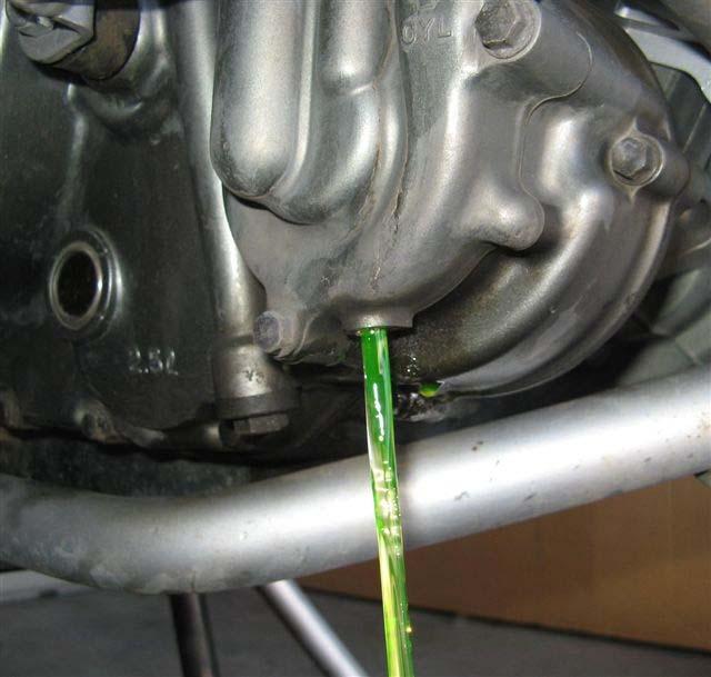
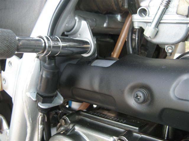
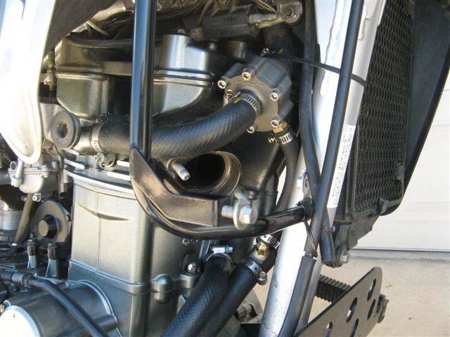
2 PREPARE THE AREA 1) Remove the right radiator shroud that is an extension of the fuel tank by removing the two bolts that retain the shroud through the coolant overflow tank, and the upper screw that attaches the shroud to the fuel tank. Release the plastic nipple where the shroud pops in to the rubber grommet at the lower front of the tank, and remove the shroud. 2) Remove the front fender (four bolts). It s very easy to remove and will make your work easier. Then remove the engine skid plate and the black cover from the coolant overflow tank. 3) You now need to remove the overflow tank. First, slide the upper vent hose off of the nipple on the top of the overflow tank as shown in Figure 2. Be careful not to break the nipple off of the plastic overflow tank it usually helps to twist the hose first to break it loose. On the bottom of the overflow tank, you ll see a second hose but don t remove it from the tank here or coolant will pour out. Instead, remove the black screw-on fill cap. Then remove the final two bolts that hold the overflow tank to the frame, and invert the tank over a drain pan to empty out the contents. Loosely reinstall the overflow tank cap, remove the lower hose from the overflow tank nipple (again, be careful, it s plastic and has lived near the exhaust pipe since the bike was new!) and set the overflow tank aside. It is recommended that you inspect to verify that the lower nipple is truly open, there have been instances where KLR s are assembled and shipped with that nipple plugged! This is also a good time to flush the inside of the overflow tank, as it has probably never been cleaned since the bike was new. 4) Carefully remove the radiator cap after the engine is cool and pressure has been relieved from the cooling system. If you do this while the coolant is still hot, you will burn yourself. 5) Drain the coolant into a suitable container, remembering to keep it away from children and pets due to the toxicity. The drain plug (8mm head) is in bottom of the water pump housing as shown in Figures 3a and 3b. Approximately oz of coolant will drain. Reinstall the drain plug in the bottom of the water pump with its sealing washer, and torque to 70 inch-pounds (that s only 5.75 foot-pounds). 6) Your next task is to remove the exhaust headpipe. I have found this to provide more room, and be easier than the old method, which was to remove the side covers, seat, fuel tank and left radiator shroud. There are a few things in the way of removing the headpipe so first remove the two screws that retain the rear master cylinder cover as shown in Figure 4, then remove the one 10mm head bolt that holds on the rear master cylinder reservoir as shown in Figure 5a. Now loosen the rear exhaust clamp (Figure 5b) about 6 turns and open the clamp slightly to release any clamping load, then remove the one 12mm-head bolt that holds the headpipe to the frame (Figure 5c). We re getting close. Remove the two 12 mm-head acorn nuts that hold the headpipe to the cylinder as shown in Figure 5d, then slowly remove the headpipe from the bike by pulling it forward as shown in Figure 6. NOTE: pay attention to the copper crush washer (Red arrow in Figure 6). Unless you have a new one ready to go, it is recommended to keep track of the washer s orientation so that upon reassembly, you can put it back in the same way that it was before. 7) OK. Now you have a good view of where you re going to work. Figure 7 shows the three main hoses involved in the KLR cooling system (the exhaust pipe was still installed when this photo was taken). All hoses have been colored to help in identification. Two of the three hoses will be modified to install this kit. The upper hose (red/purple) will have the Thermo-Bob installed in it. The lower blue hose will have the tee fitting installed in it. Note that the blue hose attaches to the REAR nipple on the water pump housing. The lower gold hose will stay as-is, do not cut it up. Did you catch that? If you mistakenly install the tee fitting in the GOLD hose instead of the BLUE hose, there will be no coolant flow, the engine will overheat and engine damage could result. 2007, Watt-man LLC. All Rights Reserved. Watt-man LLC is the author of this document for purposes of copyright and other laws. Page 2
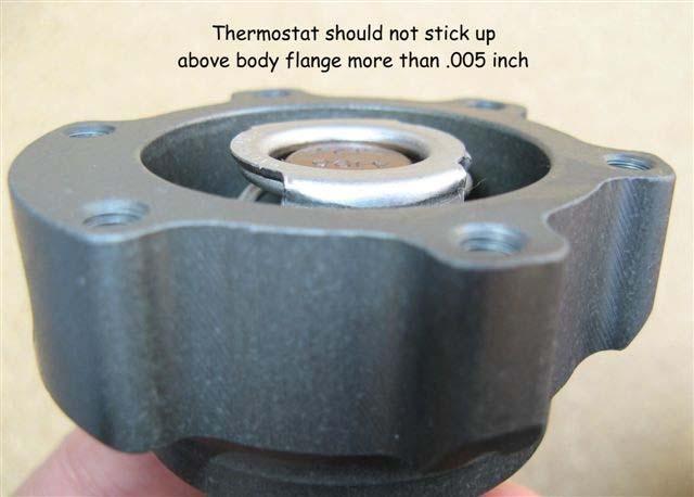
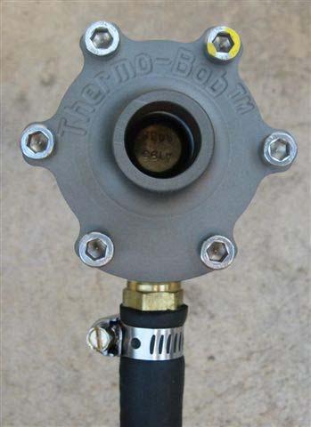
3 ASSEMBLE THE THERMO-BOB (Steps 8 through 11 have already been completed for you but are spelled out below if you ever take the Thermo-Bob apart in the future.) 8) Locate the thermostat from the kit and verify that the retention tabs have been cut off as shown in Figures 8 and 9. The thermostat will not fit in the housing until the tabs are removed. 9) Lubricate the outside diameter of the thermostat s rubber seal and the inside of the Thermo-Bob housing with a thin film of coolant as shown in Figure 10. Then push the thermostat into the housing as shown in Figure 11. Before pushing it in, orient the thermostat in the housing as shown in Figure 12. It is important to push it in firmly until it bottoms squarely in the housing and does not protrude more than above the edge as shown in Figure ) Lubricate the large, skinny o-ring with coolant and install it in the housing cap as shown in Figures 14 and 15. Be sure it is down in the groove all the way around. Then install the cap onto the housing - Figure 16 reminds you that the o-ring will slightly separate the housing and cap. Install the six housing screws. They should spin in easily: if one does not, back the screw out a turn and try again. Install them finger tight, then tighten them in a cross-pattern, ½ turn at a time to seat the cap against the housing as shown in Figure 17. Finally, torque the screws to 45 to 50 in-lb. 11) Place a thin layer of pipe dope (not provided) around the threaded end of the straight brass hose barb and thread it into the bypass port on the Thermo-Bob. The hose barb and housing use tapered pipe thread, so the effort required to continue turning the fitting will increase as you continue - snug it up good. Your finished product should look like Figure 18. Note how water moves through the part so that you can install it properly. UPPER HOSE MODIFICATION AND OLD THERMOSTAT REMOVAL 12) Measure along the outside bend of the upper radiator hose as shown in Figure 19 and mark the hose at a distance of 7.0 inches and 8.5 inches from the engine end. Cut the upper radiator hose at those two points, being cautious to make a straight cut that is perpendicular to the axis of the hose. Depending on how your upper hose was originally connected to your original thermostat housing nipple, you might find it helpful (see Figure 20) to loosen the radiator clamp at the original thermostat housing, slide the hose out 0.25 inches further on the nipple, and then retighten the clamp, being certain that the clamp is still to the left of the barb on the nipple. This might help you in step ) Loosen and then remove the three bolts (8mm head) on the factory thermostat housing the bolts are circled in red in Figure 21. In the side of the cylinder head you ll see the original thermostat and gasket as shown in Figure 22. Remove them as shown in Figure 23. This is where the small, fat o-ring is going to be installed as shown in Figure 24. Inspect the sealing surfaces -a few gentle swipes with fine sandpaper will clean this surface up if necessary, then wipe clean with a damp cloth to remove any grit that may be left behind. Lubricate the o-ring with coolant and place the factory thermostat housing over the o-ring. IMPORTANT: Be careful installing this run the bolts down finger tight, then turn each bolt ½ turn at a time in succession to slowly seat the housing against the cylinder head, then torque to 70 inch- 2007, Watt-man LLC. All Rights Reserved. Watt-man LLC is the author of this document for purposes of copyright and other laws. Page 3
4 pounds (that s only 5.75 ft-lb). If you don t do this shared method of tightening the housing bolts and crank only one bolt all the way down first, you will damage or break an ear off the factory housing. 14) Install the Thermo-Bob in the gap of the upper radiator hose for a trial fit without clamps. During this trial fit, your goal is to place the Thermo-Bob in its final location that doesn t touch the frame downtube, overflow tank or cam cover / cylinder head. Note in Figure 25 how the Thermo-Bob is clocked about 30 degrees counter-clockwise to improve clearance between the housing s lugs and the cylinder head. Without using any bolts, place the overflow tank back in its normal location by hand to verify that you will not have contact between the Thermo-Bob and overflow tank as shown in Figure 26. If you find that they touch, you should cut another bit off the upper hose on the radiator side, which will pull the Thermo-Bob to the left side of the bike a bit further. It is possible to have light contact between the Thermo-Bob and the cylinder head at this stage. The tie-wrap (coming up in step 18) will allow you to pull the Thermo-Bob slightly away from the cylinder head. As shown in Figure 27, place alignment markings on the hose on each side of the Thermo-Bob. Remove the Thermo-Bob from the bike and locate the piece of bypass hose from the kit. Dip one end of the bypass hose into coolant, wipe off the outside and slide the wetted hose end onto the brass hose barb on the bottom of the Thermo-Bob. Install and tighten a small clamp from the kit in the orientation shown in Figure 28. Locate two large clamps from the kit, then using your alignment markings, install the Thermo-Bob in the upper radiator hose as shown in Figure 29. Tighten both new clamps properly to hold the Thermo-Bob in place. LOWER HOSE MODIFICATION 15) Please note back in Figure 7 that I ve also colored the two lower coolant hoses; one goes from the radiator to the water pump (colored blue) and the other goes from the water pump to the bottom of the cylinder (colored gold). The blue hose will have the tee fitting installed in it. Remove the two clamps that hold the lower ( blue ) hose to the KLR and remove the hose. On the radiator tank end, mark and cut out a ¾ inch long section of hose that occupies the 2 ¼ to 3 placement from the end as shown in Figure ) As shown in Figure 31, reinstall the lower hose on the bike with the tee fitting oriented as shown in the lower hose, plus two new large clamps from the kit. When you re happy with the brass barb orientation, tighten all four large clamps that hold the lower hose to the KLR as well as the Tee Fitting. 17) It is now time to determine the proper length for the bypass hose. It is provided a little too long on purpose to accommodate variations in each installation. If you leave the bypass hose too long, it might kink and restrict bypass flow, resulting in the thermal cycling that the original cooling system is known for. As shown in Figure 31, push the bypass hose over against the side of the bypass barb and mark the hose where it should be cut (yellow line in Figure 31). After cutting the bypass hose at that point, slide the remaining small radiator clamp from the kit up the hose, dip the free end of the bypass hose in coolant (I lift a small cup of coolant up to the hose), wipe off the outside and slide it onto the bypass barb. Slide the loose small clamp down the bypass hose and tighten it appropriately. 18) Inspect for interference between hoses and metal parts that could rub a hole in them. If you are concerned about clearances anywhere, the tie wrap provided in the kit can be used to apply tension in the direction you wish, but the most common use is to pull the Thermo-Bob slightly forward towards the frame downtube to improve clearance between the Thermo-Bob and the cylinder head. Installation is now 2007, Watt-man LLC. All Rights Reserved. Watt-man LLC is the author of this document for purposes of copyright and other laws. Page 4
5 complete, it should look like Figure 32. Make one final check of all radiator hose clamps to be sure they re all tightened properly. 19) Reinstall the exhaust pipe and crush washer (Figure 6 then 5d), placing the copper crush washer in the same orientation in which you found it. Install the two acorn nuts in a shared method to place the exhaust collar parallel to the cylinder head then torque both to 15 ft-lb. I ll remind you here that you will need to retorque these two fasteners to 15 ft-lb a second time after the engine has been through a thermal cycle, as the crush washer might relax. Reinstall and torque the headpipe-to-frame clamp (Figure 5c) and rear exhaust clamp (Figure 5b), torquing both to 15 ft-lb as well. Reinstall the rear master cylinder reservoir (Figure 5a, 40 inch-lb), and rear master cylinder cover (Figure 4, two phillips screws). 20) Reinstall the overflow tank with two bolts in the holes closest to the frame downtube (40 inch-lb). Reconnect the two small hoses to the overflow tank nipples. Remove the fill cap, and pour 14 oz. of 50/50 coolant into the overflow tank. Tighten the cap. REFILL THE COOLING SYSTEM 21) The cooling system typically holds about 38 oz of 50/50 coolant, but without a bleed hole in the thermostat, filling the cooling system is a little more complex. Fill the radiator nearly to the top by pouring in 50/50 coolant this should take around 28 fluid oz. Start the engine and let the bike run between 1000 and 2000 rpm with the radiator cap off. By running the engine for less than 30 seconds, the air should be purged in the system and the coolant level will drop in the radiator. Shut off the engine and you should be able to add the final 10 oz. of coolant. Then replace the radiator cap, being sure it is on correctly. 22) Replace the black coolant overflow tank cover, skid plate, front fender and right radiator shroud. Torque all bolts to Kawasaki specification. It s time for a test ride! 23) Ride the bike a short distance to allow the cooling system to heat and pressurize itself so you can conduct leak checks. Once home, let the bike completely cool. Then you can remove the radiator cap again to be sure the system is truly topped off. Check all hose clamps one more time, and retorque the two 12 mm-head acorn nuts that hold the exhaust headpipe to the cylinder one final time at 15 ft-lb. Installation is complete. If you have any comments or questions, contact me at watt-man@cox.net. 2007, Watt-man LLC. All Rights Reserved. Watt-man LLC is the author of this document for purposes of copyright and other laws. Page 5
 these four thermostats can be referenced with eight different part numbers.")

6 REPLACEMENT PARTS (Recommended replacement frequency: every 5 years or 40,000 miles, whichever comes first) The replacement thermostat is produced by STANT, and four different thermostats will fit. Due to the fact that Stant has two different ways to reference a particular part (the catalog usually uses the box number) these four thermostats can be referenced with eight different part numbers. The photos below clarify the Stant numbering scheme. Unless special ordered, your Thermo-Bob was shipped with a STANT which is a 195 F thermostat. Do not try to crossreference the part number to a different brand, they typically will not fit properly. If you are unable to find parts locally, replacement thermostats are available below and include shipping fees to the US or Canada: Thermostat: $12 O-ring kit: $5 (includes both o-rings from the kit one large/skinny and one small/fat ). There are two methods to provide payment: 1) A personal check or money order to: Watt-man LLC 6501 E. Greenway Pkwy # Scottsdale, AZ and at the same time, send an to watt-man@cox.net so I'll be able to box up your order and wait for your check. 2) PayPal to watt-man@cox.net If you need other parts (brass fittings, aluminum housing pieces etc.) contact me as well. Same address as above. IM07 V9c 2007, Watt-man LLC. All Rights Reserved. Watt-man LLC is the author of this document for purposes of copyright and other laws. Page 6

7 Figure 1 Thermo-Bob kit contents.


8 Figure 2 Figure 3a Figure 3b


9 Figure 4 Figure 5a Figure 5b Figure 5c


10 Figure 5d Figure 6 (Red Arrow points to copper crush washer)

11 Figure 7


12 T-stat with full tabs still in place T-stat with tabs cut off Figure 8 Figure 9


13 Figure 10 Figure 11 Figure 12 Figure 13


14 Figure 14 Figure 15


15 Figure 16 Figure 17 Figure 18

16 Figure 19

17 Figure 20


18 Figure 21 Figure 22 Figure 23 Figure 24


19 Figure 25 Figure 26

20 Figure 27 Figure 28


21 Figure 29 Figure 30

22 Figure 31 Figure 32
Thermo-Bob 3 Installation Manual: KLR650E (2008 and newer)
") Thermo-Bob 3 Installation Manual: KLR650E (2008 and newer) Thank you for purchasing the Thermo-Bob 3 radiator bypass system for the KLR650. Since the KLR already has a doohickey, it seemed that this thingamabob
Thermo-Bob 3 Installation Manual: KLR650E (2008 and newer) Thank you for purchasing the Thermo-Bob 3 radiator bypass system for the KLR650. Since the KLR already has a doohickey, it seemed that this thingamabob
Thermo-Bob 3 Installation on a 2015-and-newer Versys 650
 Thermo-Bob 3 Installation on a 2015-and-newer Versys 650 Thank you for purchasing the Thermo-Bob 3 radiator bypass system for the Kawasaki Versys 650. Proper installation is critical: if you are not familiar
Thermo-Bob 1 Installation Manual: Kawasaki Concours
 Thermo-Bob 1 Installation Manual: 1986-2006 Kawasaki Concours This is a basic guide for installing the Thermo-Bob 1 on a Kawasaki ZG-1000 Concours. The bike used in the following photos was a 1995 year
Thermo-Bob 4 Installation Manual. TB4-KT4A Kit KTM 450 SX-F KTM 450 XC-F Husky FC450
 Thermo-Bob 4 Installation Manual TB4-KT4A Kit 2013-2015 KTM 450 SX-F 2013-2015 KTM 450 XC-F 2013-2015 Husky FC450 Watt-man.com October 2016 Thermo-Bob 4 Installation: TB4-KT4A Kit Proper installation is
DrVanos.com Stage II Installation Instructions. Tool rental is available with the purchase of a vanos kit *See website for more info*
 DrVanos.com Stage II Installation Instructions Special Tools Needed: Camshaft locking tool TDC Crank pin Sprocket turning tool Tool rental is available with the purchase of a vanos kit *See website for
BMK-18 U.S. Patent #5,298,158
 BMK- U.S. Patent #5,29,5 Marine Dual Remote Filtration System Mounting Kit Installation and Servicing Instructions IMPORTANT NOTICE Read all instructions completely before attempting to install this unit.
Procharger Stage II Intercooled Supercharger System (11-14 GT)
") Procharger Stage II Intercooled Supercharger System (11-14 GT) Installation Time: Approximately one day. Installed on 2012 Mustang GT 5.0/Manual Required Tools 3/8 Socket Set (Standard and Metric) 1/2
Procharger Stage II Intercooled Supercharger System (11-14 GT) Installation Time: Approximately one day. Installed on 2012 Mustang GT 5.0/Manual Required Tools 3/8 Socket Set (Standard and Metric) 1/2
PORSCHE V r Valve Timing Instructions. Copyright 2009 Written by Mike Frye Edited my Adam G.
 PORSCHE 928 32V r Valve Timing Instructions Copyright 2009 Written by Mike Frye Edited my Adam G. Sections: Overview.3 Disclaimer/warnings/things to watch for 4 Terms and naming conventions used in this
BEW engine timing belt replacement procedure from MOGolf (as demonstrated on a 2004 Jetta).
.") BEW engine timing belt replacement procedure from MOGolf (as demonstrated on a 2004 Jetta). Based on the procedure published by Volkswagen, but modified for the "average" shadetree mechanic. Some special
BEW engine timing belt replacement procedure from MOGolf (as demonstrated on a 2004 Jetta). Based on the procedure published by Volkswagen, but modified for the "average" shadetree mechanic. Some special
OIL COOLER KIT INSTALLATION INSTRUCTIONS PART NUMBER D E92 335i/xi (N55 engine) with M-Technic bumper and without stock oil cooler
 with M-Technic bumper and without stock oil cooler") OIL COOLER KIT INSTALLATION INSTRUCTIONS PART NUMBER D570-0925 APPLICATION 2011-12 E92 335i/xi (N55 engine) with M-Technic bumper and without stock oil cooler Congratulations for being selective enough
OIL COOLER KIT INSTALLATION INSTRUCTIONS PART NUMBER D570-0925 APPLICATION 2011-12 E92 335i/xi (N55 engine) with M-Technic bumper and without stock oil cooler Congratulations for being selective enough
OIL COOLER KIT INSTALLATION INSTRUCTIONS PART NUMBER D E92 335i/xi (N55 engine) with BMW Standard bumper and with stock oil cooler
 with BMW Standard bumper and with stock oil cooler") OIL COOLER KIT INSTALLATION INSTRUCTIONS PART NUMBER D570-0924 APPLICATION: 2011-12 E92 335i/xi (N55 engine) with BMW Standard bumper and with stock oil cooler Congratulations for being selective enough
OIL COOLER KIT INSTALLATION INSTRUCTIONS PART NUMBER D570-0924 APPLICATION: 2011-12 E92 335i/xi (N55 engine) with BMW Standard bumper and with stock oil cooler Congratulations for being selective enough
OIL COOLER KIT INSTALLATION INSTRUCTIONS PART NUMBER D
 OIL COOLER KIT INSTALLATION INSTRUCTIONS PART NUMBER D570-0904 APPLICATION: 2011-2012 E90 335i/xi (N55 engine) with BMW standard bumper and with stock oil cooler Congratulations for being selective enough
Prerequisites: Shop Manual (recommended) pages 3-9 through 3-13.
 pages 3-9 through 3-13.") Prerequisites: Order your gaskets average about $25.00 bucks X 2 so $50.00 4NK-11193-00-00 Obtain a shim kit (Should have several 265 and 270s) (Some dealers will exchange) Obtain a Valve Bucket Tool YM-33961
Prerequisites: Order your gaskets average about $25.00 bucks X 2 so $50.00 4NK-11193-00-00 Obtain a shim kit (Should have several 265 and 270s) (Some dealers will exchange) Obtain a Valve Bucket Tool YM-33961
 Special Tools Needed: DrVanos.com Stage I Installation Instructions Camshaft locking tool TDC Crank pin Sprocket turning tool Tool rental is available with the purchase of a vanos kit *See website for
In summary, the procedures includes removal of the belly pans, draining of the engine block, draining of the radiator, coolant mixing and refilling.
 COOLANT DRAIN AND CHANGE PROCEDURE Recently, there was a request for a picture guide for draining/changing coolant (Robot808 and James-man) and since I was going to do this operation on Idaho (88), I took
Dual Remote Filtration System Installation and Servicing Instructions
 IMPORTANT NOTICE Read all instructions completely before attempting to install this unit. Improper installation could result in serious system and/or equipment damage. The installation of this system is
Porsche 928 with 16v LH-Jetronic Fuel System
 Porsche 928 with 16v LH-Jetronic Fuel System Toll-Free Tech Hot Line: 877-FOR-928M 877-367-9286 Please do not copy this manual and give copies to your friends. Our ability to bring you this supercharger
CALIFORNIA TRIMMER MOWER MAINTENANCE MANUAL
 CALIFORNIA TRIMMER MOWER MAINTENANCE MANUAL 2 Table of Contents Section 1: General Information Page Handle Assembly Instructions 4 Maintenance All Models 6 Oil Change Procedures All Models 9 Height Adjustment
2015 WRX Engine Oil Cooler
 2015 WRX Engine Oil Cooler 2014-04-24 Thank you for purchasing this PERRIN product for your car! Installation of this product should only be performed by persons experienced with installation of aftermarket
OIL COOLER KIT INSTALLATION INSTRUCTIONS PART NUMBER D E92 335is (N54 engine) with BMW M-Technic bumper and with stock oil cooler
 with BMW M-Technic bumper and with stock oil cooler") OIL COOLER KIT INSTALLATION INSTRUCTIONS PART NUMBER D570-0923 APPLICATION: 2011 E92 335is (N54 engine) with BMW M-Technic bumper and with stock oil cooler Congratulations for being selective enough to
OIL COOLER KIT INSTALLATION INSTRUCTIONS PART NUMBER D570-0923 APPLICATION: 2011 E92 335is (N54 engine) with BMW M-Technic bumper and with stock oil cooler Congratulations for being selective enough to
2015+ SUBARU STI FRONT-MOUNT INTERCOOLER PARTS LIST AND INSTALLATION GUIDE INSTALL DIFFICULTY DISCLAIMER CAUTION INSTALL PROCEDURE TOOLS NEEDED
 PARTS LIST AND PARTS INCLUDED 1PC ALUMINUM INTAKE PIPE 1PC BAR-AND-PLATE INTERCOOLER 1PC STEEL CRASH BAR W/ MOUNTING HARDWARE 2PC HOT-SIDE INTERCOOLER PIPES 2PC COLD-SIDE INTERCOOLER PIPES 1PC BPV FLANGE
INSTALLATION INSTRUCTIONS COOLANT EXPANSION TANK
 INSTALLATION INSTRUCTIONS COOLANT EXPANSION TANK 2011+ FORD MUSTANG Document: 19-0147 Support: info@radiumauto.com Steps below show installation in a 2015+ Ford Mustang (P/N: 20-0286) The same procedure
Ford 6.7 EGR Delete Kit
 Fits: 2011 12 Powerstroke 6.7L Read instructions thoroughly before proceeding! ***This kit may void factory warranty please check with manufacturer.*** ***This kit is intended for off road use only.***
DUAL REMOTE OIL FILTER MODIFICATION 4 TH GENERATION FIREBIRDS
 Written by Dave Dorey (lonetechie) Copyright FirebirdNation.com The following article details how I installed a dual remote oil filter system on my 2001 Formula Firebird. If you decide to tackle this project,
2006 Honda Civic SI Supercharger Kit Installation Instruction Kit #
 2006 Honda Civic SI Supercharger Kit Installation Instruction Kit #350-091 3239 MONIER CIRCLE, STE.5 RANCHO CORDOVA, CA 95742 916.635.4550 FAX 916.635.4632 www.ct-engineering.com INS-157 VERSION: 3.25.2009
M52tu-M54 VANOS Assembly & Timing Using G.A.S. Professional Cam Tool Kit
 Home BMW Solutions Porsche Solutions DIY Tech Engine Services Dyno Services Machining About Contact Store Tool Rental M52tu-M54 VANOS Assembly & Timing Using G.A.S. Professional Cam Tool Kit This procedure
ZX-14 Stage I Turbo Kit
 62910 Peerless Ct. Bend, OR 97701 Phone 541.385.0706 Fax 541.382.9406 ZX-14 Stage I Turbo Kit WARNING: This turbo kit is for OFF-ROAD RACING use ONLY. Advisement: These instructions are written to be comprehensive
Thompson Automotive Products
 Installation instructions for Quick-Change Oil Filter relocator for NB (1999+) Miatas (MX-5) Before beginning, get your car up where you have access to the undercarriage (Rhino Ramps work well). Tools
Disc Brake System ( For Cross-Country)
") Technical Service Instructions General Safety Information Disc Brake System ( For Cross-Country) SI-8C60F t WARNING Please use extra caution to keep your fingers away from the rotating disc brake rotor
Technical Service Instructions General Safety Information Disc Brake System ( For Cross-Country) SI-8C60F t WARNING Please use extra caution to keep your fingers away from the rotating disc brake rotor
Return to Instruction Sheet index. Installation Instructions For C-4 70 and Later, Except 70 Falcon
 Page 1 of 8 Return to Instruction Sheet index TCI 260100 Trans-Scat Automatic Transmission Installation Instructions For C-4 70 and Later, Except 70 Falcon TCI 260100 Kit Contains: Qty. Description One
We thank you for purchasing a manual petcock conversion kit from Murphs!
 We thank you for purchasing a manual petcock conversion kit from Murphs! The first step is removing the gas tank from the bike. We suggest running the tank down to reserve before removal, both for the
Ford Racing BOSS 302 Engine Oil Cooler (11-14 GT)
") Tools needed: 14mm hex socket 7mm socket/wrench 8mm socket/wrench Ford Racing BOSS 302 Engine Oil Cooler (11-14 GT) 10mm socket (for airbox removal) ¾ inch or 19mm wrench Torque wrench Appropriate ratchets
Tools needed: 14mm hex socket 7mm socket/wrench 8mm socket/wrench Ford Racing BOSS 302 Engine Oil Cooler (11-14 GT) 10mm socket (for airbox removal) ¾ inch or 19mm wrench Torque wrench Appropriate ratchets
CBEA/CJAA Timing belt procedure. Written by: greengeeker Photos by: DanG144, Kriesel, coalminer16. Required tools:
 CBEA/CJAA Timing belt procedure Written by: greengeeker Photos by: DanG144, Kriesel, coalminer16 Required tools: 1. Securing pin 3359 (you need two of them!) 2. Crankshaft stop T10050 3. Counter-hold tool
2016+ NISSAN TITAN XD
 PARTS LIST AND PARTS INCLUDED 1PC MISHIMOTO INTERCOOLER 2PC SILICONE BOOTS WITH DURACORE TECHNOLOGY 4PC CONSTANT-TENSION T-BOLT CLAMPS 2PC ALUMINUM SPACERS MOUNTING HARDWARE CAUTION Never work on the cooling
1 Green Pressure Regulator Spring Automatic transmissions operate at temperatures between 150ºF and
 Installation Instructions for 603107 Valve Body Kit C-4 1970 & Later Tools Required Speed Handle or Ratchet 3/8 Drive 1/2 Socket 3/8 Drive 7/16 Socket 3/8 Drive 5/16 Socket 3/8 Drive Small Screwdriver
OIL COOLER KIT INSTALLATION INSTRUCTIONS PART NUMBER D
 OIL COOLER KIT INSTALLATION INSTRUCTIONS PART NUMBER D570-0907 APPLICATION: 2011-12 E90 335i/xi (N55 engine) with BMW M-Technic bumper and without stock oil cooler Congratulations for being selective enough
RAMPAGE POWER LIFT RAMP
 RAMPAGE POWER LIFT RAMP INSTALLATION AND OPERATING INSTRUCTIONS (3/10/07) The Rampage Power Lift Ramp is the fast, easy, and safe way to load a motorcycle into a truck. One person can load or unload a
Ford Focus Zetec SVT Timing Belt
 2000-2004 Ford Focus Zetec SVT Timing Belt Replacement This guide will show you how to replace the timing belt on the 2.0L DOHC Zetec with VCT on a 2002 Ford Focus SVT. This is an interference motor. Written
INSTALLATION INSTRUCTIONS
 COLD AIR INTAKE INSTALLATION INSTRUCTIONS PART NUMBER D760-0390C APPLICATION: 1999-2003 E39 M5 PARTS LIST 1 Left Aluminum Intake Tube 1 Air Pump Bracket (A) 1 Right Aluminum Intake Tube 1 Air Pump Bracket
Multistrada (MTS) Tank Installation Notes. Tools Required. Phase 1: Remove Fairings. Phase 2: Remove Fuel Tank
 Tank Installation Notes. Tools Required. Phase 1: Remove Fairings. Phase 2: Remove Fuel Tank") The California Cycleworks MTS tank provides an aftermarket alternative to the OEM nylon fuel tanks as used on aircooled Desmodue Ducati Multistrada 1100, 1000, and 620 models. This fuel tank is NOT for
The California Cycleworks MTS tank provides an aftermarket alternative to the OEM nylon fuel tanks as used on aircooled Desmodue Ducati Multistrada 1100, 1000, and 620 models. This fuel tank is NOT for
Powerglide Automatic Floor Mount Shifter Installation Instructions
 Powerglide Automatic Mount Installation Instructions Building American Quality With A Lifetime Warranty! TOLL FREE 1-877-469-7440 (865) 966-2269 FAX (865) 671-1999 tech@lokar.com www.lokar.com Powerglide
OIL COOLER KIT INSTALLATION INSTRUCTIONS D Application: , E89 Z4 sdrive 35i without stock oil cooler* PARTS LIST
 OIL COOLER KIT INSTALLATION INSTRUCTIONS D570-0891 Application: 2009-11, E89 Z4 sdrive 35i without stock oil cooler* PARTS LIST Qty Part No. Description 1 D573-0050 Oil Cooler + Frame Assy 1 D573-0044
Instant Chat off the main page of Or simply call our tech team at
 FRONT MOUNT INTERCOOLER 2015+ WRX 2017-07-07 Thank you for purchasing this PERRIN product for your car! Installation of this product should only be performed by persons experienced with installation of
v Porsche 928
 1985-86 32v Porsche 928 Toll-Free Tech Hot Line: 877-FOR-928M 877-367-9286 Please do not copy this manual and give copies to your friends. Our ability to bring you this supercharger kit at this price relies
BMK-27. Dual Remote Filtration System Mounting Kit. Installation and Servicing Instructions (DURAMAX) C. Oil Supply
 C. Oil Supply") IMPORTANT NOTICE Read all instructions completely before attempting to install this unit. Improper installation could result in serious system and/or equipment damage. The installation of this system is
IMPORTANT NOTICE Read all instructions completely before attempting to install this unit. Improper installation could result in serious system and/or equipment damage. The installation of this system is
BEFORE BEGINNING INSTALLATION
 COMPLETE CHASSIS FUEL LINE KITS For 1996-2000 Honda Civic Equipped with B-Series Engine INSTALLATION INSTRUCTIONS PLEASE study these instructions carefully before beginning this installation. Most installations
WRX/STI Engine Oil Cooler
 2002-14 WRX/STI Engine Oil Cooler 2014-04-21 Thank you for purchasing this PERRIN product for your car! Installation of this product should only be performed by persons experienced with installation of
DESCRIPTION MECHANICAL FUEL PUMP FUEL FILTER HIGH PRESSURE (35-90 PSI) HIGH PRESSURE (35-90 PSI) (STEEL/INCLUDED)
 HIGH PRESSURE (35-90 PSI) (STEEL/INCLUDED)") Edelbrock EFI Universal Fuel Sump System - Adjustable Part #36031, 36032, 36033, 36034 INSTALLATION INSTRUCTIONS PLEASE study these instructions carefully before beginning this installation. This installation
Edelbrock EFI Universal Fuel Sump System - Adjustable Part #36031, 36032, 36033, 36034 INSTALLATION INSTRUCTIONS PLEASE study these instructions carefully before beginning this installation. This installation
Mishimoto Performance Aluminum Radiator w/ Stabilizer - Manual (97-04 GT, Mach 1; Cobra)
") Mishimoto Performance Aluminum Radiator w/ Stabilizer - Manual (97-04 GT, Mach 1; 97-01 Cobra) Installed on: 2000 Mustang GT (manual transmission) Tools: 8mm socket 10mm socket 13mm socket 3/4" wrench
Mishimoto Performance Aluminum Radiator w/ Stabilizer - Manual (97-04 GT, Mach 1; 97-01 Cobra) Installed on: 2000 Mustang GT (manual transmission) Tools: 8mm socket 10mm socket 13mm socket 3/4" wrench
Do not have any open flame or heat sources close to the installation
 March 6, 2017 IS# 791 Page 1 of 16 Thank you for purchasing a Transfer Flow, Inc. 50-gallon replacement fuel system for your 2011-16 Ford diesel short bed pickup. This system will fit any 2x4 or 4x4 crew
M7 R52S & R53 Cold Air Intake Installation Guide 53-3M7301
 M7 R52S & R53 Cold Air Intake Installation Guide 53-3M7301 M7 Speed engineers and manufactures the highest quality MINI COOPER accessories and performance parts available anywhere on Planet Earth! Please
Switchback Carrier Rack System
 Switchback Carrier Rack System Installation Instructions 1 Rocky Mountain Westy Ph. (970)310-3441 Introduction Thank you for purchasing the Rocky Mountain Westy Switchback Carrier Rack System. We pride
Cable Shift Linkage Kit
 Cable Shift Linkage Kit INSTALLATION INSTRUCTIONS ididit column to GM Trans FOR PART NUMBER S: 2801000010, 2802000010 ididit Column to 350 Trans...Pg 1-4 ididit Column to 400 Trans...Pg 5-8 ididit Column
2017+ L5P Duramax 3 ½ Down Pipe & EGR Fix Kit
 2017+ L5P Duramax 3 ½ Down Pipe & EGR Fix Kit Covers installation of PN s: WCF100630, WCF100829 Note: This Kit is for off road competition use only! Off Road Competition Use Tuning & Exhaust System is
BMK-12. Dual-Gard By-Pass Filter Mounting Kit Installation and Servicing Instructions
 BMK-12 Dual-Gard By-Pass Filter Mounting Kit Installation and Servicing Instructions IMPORTANT NOTICE Read all instructions completely before attempting to install this unit. Improper installation could
W C-230 Kompressor Sports Sedan 1.8l Thermostat Replacement & Antifreeze flush
 W203 2003 C-230 Kompressor Sports Sedan 1.8l Thermostat Replacement & Antifreeze flush First, I have to thank everyone who has contributed to the MBworld.org forums without you; I would not have gotten
'99-03 CHEVROLET/GMC IFS 4WD 6" SUSPENSION SYSTEM P/N INSTALLATION INSTRUCTIONS
 1/16/04 '99-03 CHEVROLET/GMC IFS 4WD 6" SUSPENSION SYSTEM P/N. 10-41099 INSTALLATION INSTRUCTIONS NOTE: Each Lift Kit and options to Lift Kits are packaged separately. Therefore, installation procedures
Edelbrock EFI Universal Fuel Sump System - Adjustable Part #36031, INSTALLATION INSTRUCTIONS
 Edelbrock EFI Universal Fuel Sump System - Adjustable Part #36031, 36032 INSTALLATION INSTRUCTIONS PLEASE study these instructions carefully before beginning this installation. This installation can be
CBEA/CJAA Timing belt procedure. Written by: greengeeker Photos by: DanG144, Kriesel, coalminer16. Required tools:
 CBEA/CJAA Timing belt procedure Written by: greengeeker Photos by: DanG144, Kriesel, coalminer16 Required tools: Securing pin 3359 (need two of them!) Crankshaft stop T10050 Counter-hold tool T10172 Special
WARNING: the engine does not come with oil in it. Please fill the oil before starting. The 200cc hardknock requires 9/10 of a quart of oil.
 WARNING: the engine does not come with oil in it. Please fill the oil before starting. The 200cc hardknock requires 9/10 of a quart of oil. Things needed for assembly. -2 tubes of blue loc-tite. I don
INSTALLATION HYPERCHARGER AIR FILTER KIT 9992
 9992 PARTS INCLUDED 1 Chrome Hypercharger Assembly with Chrome Blood Groove Trap Door and Chrome Butterflies 1 Support Bracket 1 Breather Hardware Kit, including: 2 1-1/4 Breather Bolts 2 Breather Hoses
Thank you for purchasing the Craven Speed FlexPod Complete Gauge Pod Kit For R56, R58, R59, R60 with Refresh Engines (2011+)
") Thank you for purchasing the Craven Speed FlexPod Complete Gauge Pod Kit For R56, R58, R59, R60 with Refresh Engines (2011+) Before You Start Please read instructions completely before installing. These
Thank you for purchasing the Craven Speed FlexPod Complete Gauge Pod Kit For R56, R58, R59, R60 with Refresh Engines (2011+) Before You Start Please read instructions completely before installing. These
WH Ford 2WD Steering System #2013/2015 Date 02/15/04 rev. 1
 Phone (209) 400-7200 Fax (209) 943-7923 www.wildhorses4x4.com WH Ford 2WD Steering System #2013/2015 Date 02/15/04 rev. 1 Basic system notes: This system works on 1966-1977 Broncos with manual steering
IMPORTANT INSTALLATION NOTE
 IMPORTANT INSTALL NOTE IMPORTANT INSTALLATION NOTE IMPORTANT INSTALL NOTE MISHIMOTO-SUPPLIED HARDWARE (8) PC M6 X 1.0 X 16MM FLANGE HEAD BOLT NOTE: DO NOT USE IMPACT GUN TO INSTALL SUPPLIED M6 HARDWARE
BA /02/03/04/06/07/08/13/13B/15 BIG AIR KIT (BAK) - Yamaha Road Star (99-07)
 - Yamaha Road Star (99-07)") BA-2020-00/02/03/04/06/07/08/13/13B/15 BIG AIR KIT (BAK) - Yamaha Road Star (99-07) Page: 1 Revision: 6.2-02/23/2011 Install Time: 1.5 Hours We recommend a qualified Yamaha technician install this kit
BA-2020-00/02/03/04/06/07/08/13/13B/15 BIG AIR KIT (BAK) - Yamaha Road Star (99-07) Page: 1 Revision: 6.2-02/23/2011 Install Time: 1.5 Hours We recommend a qualified Yamaha technician install this kit
DURAMAX LML EGR DELETE
 2011-2012 DURAMAX LML EGR DELETE Sinister Diesel EGR Delete Kit A B C D E F G H PACKING LIST: QTY. A B C D E F G H QTY. 1 4 1 1 1 3 1 4 Description Blue Coolant Hose M8 x 25 Hex Head Bolts Exhaust Block
IAG Street Series Air / Oil Separator (AOS) For WRX
 For WRX") P IAG Street Series Air / Oil Separator (AOS) For 2015-16 WRX Part# IAG-ENG-7152 Tools Required: Ratchet, torque wrench, extensions, needle nose pliers, hose cutter, snips/scissors, flat head screw driver,
P IAG Street Series Air / Oil Separator (AOS) For 2015-16 WRX Part# IAG-ENG-7152 Tools Required: Ratchet, torque wrench, extensions, needle nose pliers, hose cutter, snips/scissors, flat head screw driver,
VRSC-DX Truck-Lite LED Headlight Installation Instructions
 VRSC-DX Truck-Lite LED Headlight Installation Instructions The following Instructions are for installing a 7 Truck-Lite LED headlight into a Harley Davidson VRSC-DX Night Rod Special fairing. Other 7 headlights
This is a hobby website dedicated to the Kawasaki KLR650 motorcycle. I make no claim concerning the
 KLR650 Homepage Contact Me You must remove the "REMOVE-THIS" in my email address for it to work. This is a hobby website dedicated to the Kawasaki KLR650 motorcycle. I make no claim concerning the accuracy
OREGON PIONEER 15 OWNER S MANUAL
 OREGON PIONEER 15 OWNER S MANUAL SURVEYORS EXCHANGE COMPANY GEOLASER 3323 DeArmoun Road Anchorage, AK 99516 Phone: 1-507-629-3758 Cell: 1-507-828-0503 www.gold-rus.com INTRODUCTION This manual covers the
2010 Prius Maintenance
 2010 Prius Maintenance Changing Oil Disclaimer: All the information stated in this document was provided by Prius owners. None were affiliated with Toyota Motor Corporation, except as customers. This document
Retro it Steering Column
 Retro it Steering Column INSTALLATION INSTRUCTIONS for 1976-86 CJ5 & CJ7 FOR PART NUMBER S: 1520800010, 1520800020, 1520800051, 1526800010, 1526800020, 1526800051 S I NCE 1986 Instruction # 8000000010
How I installed new brake pads on my i with Sport Package (should be fine for other E39 s) By Robert B.
 By Robert B.") How I installed new brake pads on my 1999 528i with Sport Package (should be fine for other E39 s) How I installed new brake pads on my 1999 528i with Sport Package (should be fine for other E39 s) By
How I installed new brake pads on my 1999 528i with Sport Package (should be fine for other E39 s) How I installed new brake pads on my 1999 528i with Sport Package (should be fine for other E39 s) By
IAG Street Series Air / Oil Separator (AOS) For 2017 WRX
 For 2017 WRX") P IAG Street Series Air / Oil Separator (AOS) For 2017 WRX Part# IAG-ENG-7152 Tools Required: Ratchet, torque wrench, extensions, needle nose pliers, hose cutter, snips/scissors, flathead screwdriver,
P IAG Street Series Air / Oil Separator (AOS) For 2017 WRX Part# IAG-ENG-7152 Tools Required: Ratchet, torque wrench, extensions, needle nose pliers, hose cutter, snips/scissors, flathead screwdriver,
LML 3 Y-Bridge Kit or High Flow Intake Bundle Package
 2011-2016 LML 3 Y-Bridge Kit or High Flow Intake Bundle Package Covers installation of PN s: WCF100607, WCF100691, WCF100716, & WCF100353 Note: This Kit is for off road competition use only! Overview-
INSTALLATION HYPERCHARGER AIR FILTER KIT 9754
 9754 PARTS INCLUDED 1 Chrome Hypercharger Assembly 1 Support Bracket 1 Breather Hardware Kit, including: 2 1-1/4 Breather Bolts 2 Breather Hoses 4 Shim Washers 1 Twin Cam Breather Kit, Including: 1 Breather
Installation Instructions Table of Contents
 Installation Instructions Table of Contents Pre- Installation of Garage Storage Lift 2 Layout the Garage Storage Lift 3 Installing the strut Channels 3 Install the Drive Assembly 5 Install the Drive Shaft
RV-7 / RV-8 / RV-10 Installation Kit Trio Gold Standard Roll Servo
 RV-7 / RV-8 / RV-10 Installation Kit Trio Gold Standard Roll Servo Thank you for purchasing the Trio Avionics Servo Installation Kit. This guide provides a general overview for installation of the Trio
INSTALLATION INSTRUCTIONS
 INSTALLATION INSTRUCTIONS Part # 751-FP2500 IMPORTANT INFORMATION This Jagg oil cooler must be installed following these instructions. Read the easy-to-follow instructions fully prior to starting the installation
Powerstroke EGR Delete A B C
 20-203 6.7 Powerstroke EGR Delete A B C D E F G H I J K Part # A B C D E F G H I J K PACKING LIST: QTY. 3 5 2 Description Sensor Bracket Exhaust Blockoff Plate Straights Barbed Brass Fitting 39 5/8 Coolant
Exhaust Heat Shield Instructions ND
 Exhaust Heat Shield Instructions ND 2016 + Thank you for purchasing the Track Dog Racing Exhaust Heat Shield for the 2016 to Present Mazda MX-5. Our TDR Heat Shield is designed to help maintain lower temperatures
Torqueflite Manual/Automatic Valve Body
 TCI 122400 Torqueflite Manual/Automatic Valve Body This valve body can be installed in a few hours by carefully following directions. Read all instructions first to familiarize yourself with the parts
J&M Stainless Steel Teflon Brake Lines - Front (94-98 Cobra)
") J&M Stainless Steel Teflon Brake Lines - Front (94-98 Cobra) Time Required: 30min-1 hour. Tools and Supplies Required: Jack Jack Stands Lug Wrench or 13/16 Socket 10mm Socket Socket Wrench Torque Wrench
J&M Stainless Steel Teflon Brake Lines - Front (94-98 Cobra) Time Required: 30min-1 hour. Tools and Supplies Required: Jack Jack Stands Lug Wrench or 13/16 Socket 10mm Socket Socket Wrench Torque Wrench
Forge Motorsport BMW N54 Diverter Valves
 Forge Motorsport BMW N54 Diverter Valves Please thoroughly read through and familiarize yourself with these instructions in their entirety prior to beginning any part of the installation process of any
FORK FREE PISTON MODIFICATION 2011 HONDA CRF250R
 217 Lorain Place Los Gatos, California 95032 408.406.2089 www.smartperformanceinc.com www.spi-racing.com FORK FREE PISTON MODIFICATION 2011 HONDA CRF250R WHAT? All production versions of the 2011 HONDA
Z1 Motorsports 350Z / G35 Oil Cooler Kit Installation Manual
 Z1 Motorsports 2877 Carrollton Villa Rica Hwy Carrollton GA 30116 770.838.7777 Z1 Motorsports 350Z / G35 Oil Cooler Kit Installation Manual For 19, 25 and 34 Row Oil Cooler Kits Parts Included: 1 Aluminum
POWER STEERING PUMP REBUILDING SPK101 Read instructions completely before removal & disassembly
 POWER STEERING PUMP REBUILDING SPK101 Read instructions completely before removal & disassembly DISASSEMBLY: 1. Remove pump from car and allow to drain. 2. Remove pulley from front of pump. This requires
INSTALLATION INSTRUCTIONS
 INSTALLATION INSTRUCTIONS COOLANT EXPANSION TANK FORD FOCUS Document: 19-0151 Support: info@radiumauto.com WARNINGS: DO NOT WORK ON THE COOLANT SYSTEM WHEN THE ENGINE IS AT OPERATING TEMPERATURE. WAIT
Fluid-O-Tech ROTOFLOW ROTARY VANE PUMP REBUILD MANUAL
 Fluid-O-Tech PUMP TECHNOLOGY AT ITS BEST WWW.FLUID-O-TECH.COM Office: 161 Atwater St., Plantsville, CT 06479 Phone: (860) 276-9270 Fax: (860) 620-0193 ROTOFLOW ROTARY VANE PUMP REBUILD MANUAL 08/09 Ed.,
99-04 GT. Hellion Power Systems Mustang GT Kit Instructions
 Hellion Power Systems 99-04 Mustang GT Kit Instructions Part 1 Hellion recommends that the front suspension system be installed either by trained professionals or by 5.Remove rack bolts K-Member Installation
Installation Instructions COMPETITION/PLUS SHIFTER Ford Mustang MT82 6-Speed Manual Transmission Catalog#
 Installation Instructions COMPETITION/PLUS SHIFTER 2015-2017 Ford Mustang MT82 6-Speed Manual Transmission Catalog# 3916037 Rev. 00 WORK SAFELY! For maximum safety, perform this installation on a clean,
RZR 900 spring/shock installation
 RZR 900 spring/shock installation Thank you for purchasing the Shock Therapy Dual Rate Spring Kit for your RZR 900. Your item list: 2 Front upper coil springs, 2 Front lower coil springs, 2 Rear upper
ADM Performance 6079 Mapleshade Lane Dallas, Texas (214)
") 1) Disconnect Battery Ground 2) Raise front end of Vehicle FAN INSTALL INSTRUCTIONS 3) Remove lower Radiator hose and drain coolant into a pan. (you will reuse coolant later) 4) Remove Air Intake piping
1) Disconnect Battery Ground 2) Raise front end of Vehicle FAN INSTALL INSTRUCTIONS 3) Remove lower Radiator hose and drain coolant into a pan. (you will reuse coolant later) 4) Remove Air Intake piping
BMW E61 Hydraulic Pump replacement instructions
 BMW E61 Hydraulic Pump replacement instructions This DIY will guide you through the tasks needed to successfully replace your defective tailgate hydraulic pump Difficulty 3 of 10. The most difficult part
Please contact BrakeAway Products tech support for additional (503) or
 or") Congratulations on the purchase of your new BrakeAway Motorcycle Cruise Control. At BrakeAway Products, we are committed to your complete satisfaction. With proper installation, use, and periodic maintenance,
Congratulations on the purchase of your new BrakeAway Motorcycle Cruise Control. At BrakeAway Products, we are committed to your complete satisfaction. With proper installation, use, and periodic maintenance,
Installation Notes: #86000-R Race Series +3.5 L/T Kit
 159 North Maple St. Unit J, CORONA CA 92880 P. 951-737-9682 F. 951-737-9006 WWW.CHAOSFAB.COM Installation Notes: #86000-R Race Series +3.5 L/T Kit Factory manual is recommended for removal and re-installation
INSTALLATION INSTRUCTIONS FOR THE MOTOR TRIKE GL1500 RAKE KIT
 INSTALLATION INSTRUCTIONS FOR THE MOTOR TRIKE GL1500 RAKE KIT Thank you for choosing the Motor Trike GL1500 Rake Kit. We ask that you read the directions before you start and follow them very closely.
952004S STAINLESS POWER EXHAUST SYSTEM CHEVY 454 CLASS A MOTORHOME SINGLE AIR PUMP
 952004S STAINLESS POWER EXHAUST SYSTEM 75-86 CHEVY 454 CLASS A MOTORHOME SINGLE AIR PUMP Thank you very much for purchasing our Gibson Exhaust System for your vehicle. If you need further assistance, please
Disco 3 Clock Spring / Rotary Coupler replacement
 Disco 3 Clock Spring / Rotary Coupler replacement I recently had to change my Clock spring and thought some folks may find it helpful to see what it entailed. I did lots of reading around but couldn t
Kits 75559, & Universal Air Spring-Over-Strut
 Kits 75559, 75561 & 75562 Universal Air Spring-Over-Strut MN-723 (061901) ECR 8657 NOTE: THIS KIT IS SOLD WITHOUT A WARRANTY. INSTALLATION GUIDE For maximum effectiveness and safety, please read these