WARNING: the engine does not come with oil in it. Please fill the oil before starting. The 200cc hardknock requires 9/10 of a quart of oil.
|
|
|
- Kelly Copeland
- 6 years ago
- Views:
Transcription
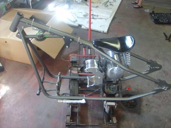
1 WARNING: the engine does not come with oil in it. Please fill the oil before starting. The 200cc hardknock requires 9/10 of a quart of oil. Things needed for assembly. -2 tubes of blue loc-tite. I don t recommend red loc-tite, because it requires heat to remove the nut, and heat can damage painted surfaces, chrome and compromise the strength of metal. -High temp bearing grease. -rubber mallet if you have one. -A sealant for the petcock. Either a liquid gasket sealer that is gasoline resistant or a thread tape that is. (Make sure what ever it is its gas resistant.) -rubber washers/rubber spacers for the gas tank mounting. -Anti-seize compound of your choice -oil for break in and oil change recommended oil is red line 20/50, what ever oil you use must be made for a motorcycle wet clutch 4 stroke engine. Do not use synthetic to break In, it does not seat seals; only organic based oil can do that. What s included in kit when you receive it, depending on your options. Your kit will come In 4 separate boxes.
2
3

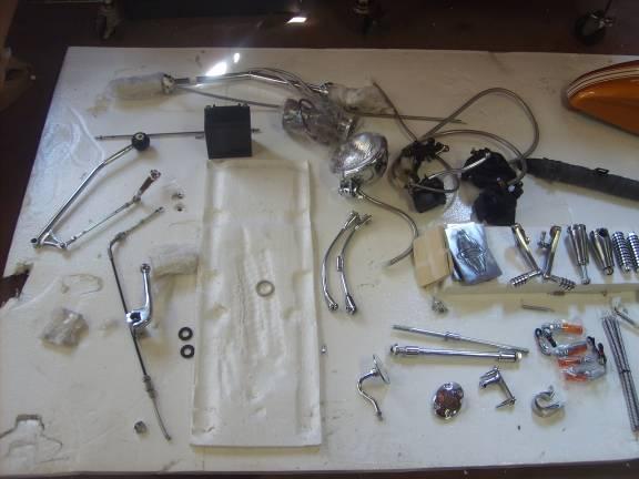
4 These pictures do not include the engine or front end, because they have already been installed on this kit. Step 1. Unpack your boxes. Take an inventory to make sure all parts are included. Do not throw any boxes or packaging away until the bike is complete, because often small parts may have fallen loose and still be in a box, or packaging. Remove battery from its box and charge it while assembling your bike. They do not come fully charged. Boxes consist of: Box 1 frame Box 2 primary components, as pictured above Box 3 tires and wheels Box 4 engine Step 2.mounting front suspension

5 This will be the correct position of the bearings and nut when assembled

6 Open up your trees as far as they will open

7 Next grease your bearings Place your bottom bearing back on the neck bolt. Than take your front suspension and place the neck bolt through the head tube and put your top bearing in the head tube and push down the top triple tree. Than put the top nut on as shown in the correct placement picture and tighten it down. It is best to get it as tight as possible. It will loosen up as it seats itself it from riding.

8 Now place your top triple tree back down than take the large head tube bolt. And put it on. It s a 30mm diameter nut. Do not tighten down you legs yet. You will do this after you align your fender and axle. So they are straight and level. Step 3. Mounting engine.

9 There may be a gap on the front lower motor mounts. This is normal during installation. Tighten down the motor mount bolts until there is no gap. Step 4. Wiring the engine First install the voltage regulator to the bottom of the engine, directly in front of the rear engine mount.

10 I chose to remove the plug from the end of the voltage regulator wires. I used a small pointed screw drew driver to do this.

11 This is a picture of how the wires are placed in the plug. After removal of the plug

12 The next step is to run the wires as hidden as possible up and into the oil can. Than place the wires back into the plug in their correct place. And plug it into the corresponding plug. Next step is to ground the starter. I grounded my starter to the inside of the rear motor mount using a small nut and bolt. Than run the starter positive into the battery box and connect to the starter solenoid, on the empty side. Step 5. Mounting front fender. While your legs are still loose enough to move place your front axle through them to get them straight and at correct height alignment. You may need or want to use a tape measure to check all measurements for correct alignment on front suspension. After you get them correct you may now tighten down your triple tree nuts, but I do not recommend you use loc-tite until you place you front wheel on. In the event that your alignment was incorrect it makes it easier to loosen up and move. Only after you are completely sure it perfect place loc-tite on the triple tree bolts.

13 These are you re your fender struts. Mount these to your front fender first. Next step is to mount you fender to the fender tabs on your legs.

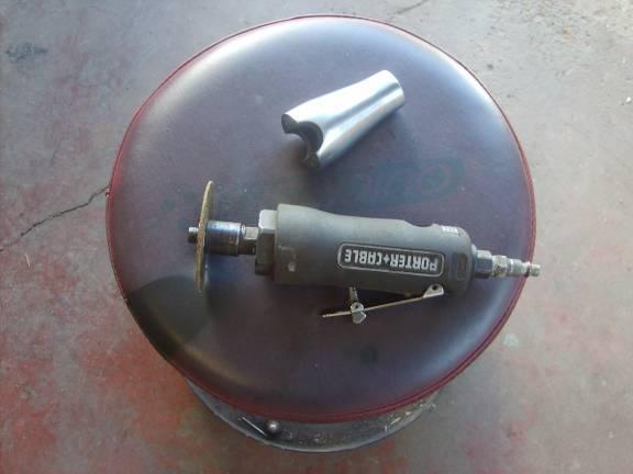
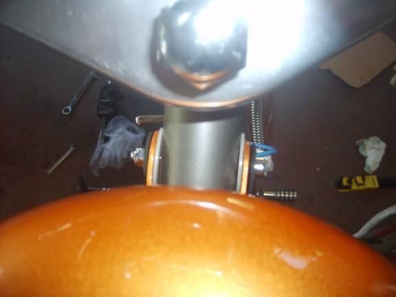
14 It should look like this from underneath when done correctly. Step 6. Installing risers First is to clean them up so they seat evenly and properly. This is the method I used.
15
16

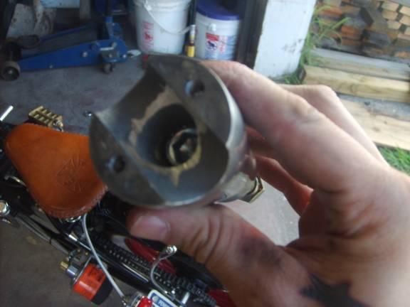
17 After you remove any excess metal from the riser and riser cap place your risers on the triple tree. You want to tighten them down

18 But not to a point where they can not be moved. You will need to align them with your bars.

19 After they are aligned tighten them down and you may now put you bars on and caps on the risers. If you are putting apes on do not over tighten the riser caps down completely until the bars are in a comfortable position for riding because you may chose to reposition them to your comfort after you can sit on the bike.

20 Step 7. Installing rear fender. Install rear fender using the two attach bolts in the center of the frame.

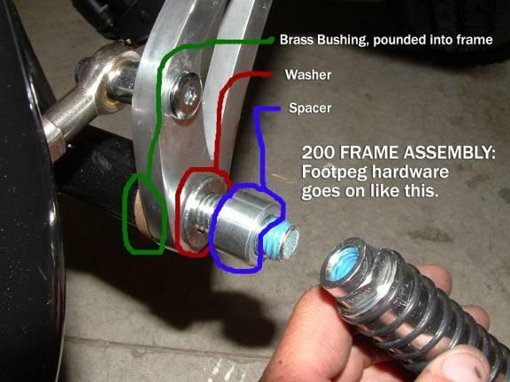
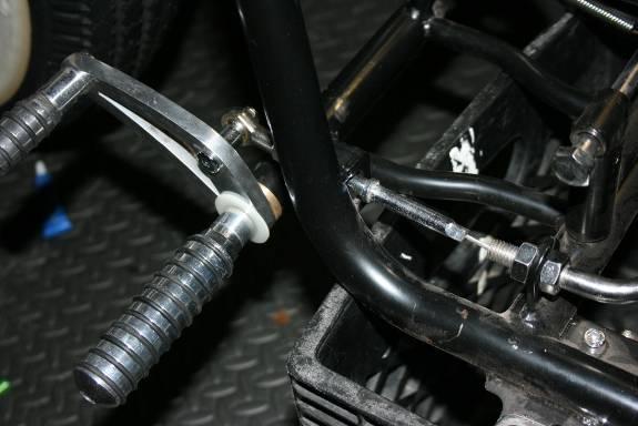
21 install rear fender brace tubes. Note that the fork end of the brace tubes attach to the frame. The left side bracket has the tail light attachment. Step 8. Forward controls.

22 Put in the axle bushings I use a socket that fits over the nipple on the bushing and GENTLY tap it into place. These are fragile so do not pound on it.
23

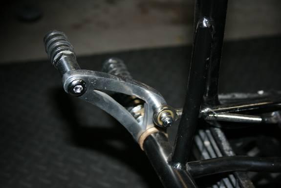
24 Step 9. Forward control clutch cable installation.
25

26 Once you have this together you will need to adjust you cable to engage your clutch properly. To adjust is simply just moving the bolts on the threaded cable adjusters forward until you have proper tension. Do not over tighten or it will cause your clutch to slip or never properly disengage.

27 Step 10. Forward control rear brake installation First you will need to install your rear brake master cylinder, and reservoir as you can see in these pictures. The master cylinder mounts near the battery box. You can mount it on top or underneath. If you mount it from the bottom you will not have to bend your brake rod, but you may sacrifice frame clearance this way. It is a matter of preference. The reservoir can be mounted here
28 I used a small spacer and nut and bolt to achieve proper clearance and to keep it place as shown here

29 After installing the master cylinder you need to install the brake rod and springs correct location is illustrated in the next 2 pictures
30
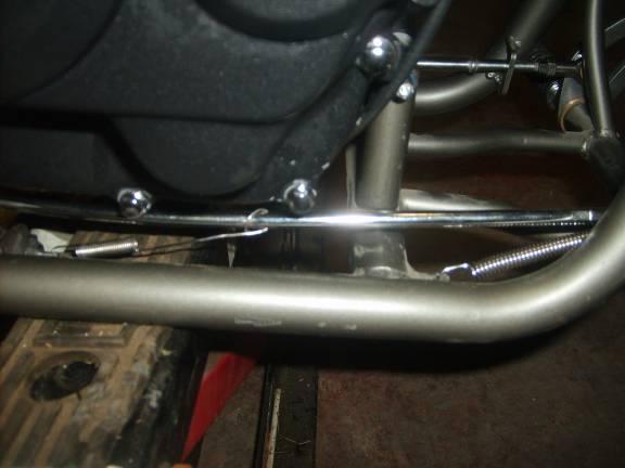
31

32 The rear spring goes through the rear brake light actuator; it has a small hole in it for the spring to go through. When doing this, make sure the spring is not to loose or to tight, or it will not engage the brake light correctly. Step 10. Installing front tire Brake rotor goes to the left side (jockey shift side) as well as the short axle spacer. Long axle spacer goes on right side. Make sure you have already installed the front fender. If you have already installed the handle bars you may now install the front brakes Step 11. Installing front brake Master cylinder and lever go on the right of the handle bars the brake light and starter safety switch plug from the brake lever plug in under the tank. And the caliper go the left side. It s very simple. 2 bolts hold it in place. It should look as it does in the picture.

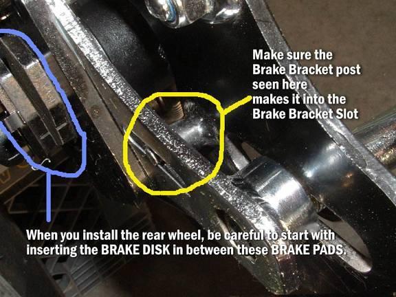
33 Step 12. Install rear tire and rear brake I found this to be one of the most difficult tasks of assembly and believe it was much easier to do with an extra person. First place your brake caliper in the correct place on the frame and slide your axle in far enough to hold it in place, than put your spacer on the end of the axle, just covering the threads. While putting the tire in place than pushing the axle through the wheel hub while leaving enough space put the chain side spacer in place. I used a small pry bar wrapped in cloth to pull open the frame to get the space on this side in place. Place the axle lock nut on the axle but do not tighten. You do not need to remove axle adjusters to assemble this picture is simply for illustration purposes to show the correct location of the rear assembly.
34 .

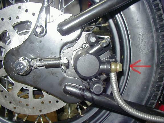
35 If caliper alignment is incorrect you may need to use washers or spacers to correct the alignment as pictured here in the caliper bracket. Four 10mm lock washers were used to get proper caliper alignment here, two on each side of the caliper mounting bracket, along with longer bolts.
36

37 Step 13 Chain installation. Your axle adjusters/chain adjusters, should be adjusted so the axle is as far forward as it will go. The chains are very tight new and it makes it difficult to get the chain on if the axle isn t completely forward. The tool. Lawn mower starter rope. OK, now I will show you how I did it. First lay out your stuff.
38 Then adjust/move the back wheel all the way forward.

39 Step 1: Hold chain ends together.

40 Step 2: Insert tool into links as shown.

41 Step 3: Tie a knot in the rope and insert a stubby or something short and strong. (Get your thing out of there. That's gross.)

42 Step 4: Twist the rope until the links come together.

43 Step 5: Insert the master link from the back side.


44 Step 6: Install your master link clips making sure that the closed end of the clip is facing the direction of travel.

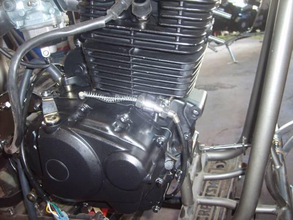
45 Now you can extract the special tool and you re done. I have used rope like this for years. It comes in handy as a spring tool when fixing drum breaks. For those who choose to walk it on, the rear sprocket has a small chain guard on it; it may get damaged during the walk on. Step14. Installing carb The carburetor comes with gaskets, to install it just requires placing it there and bolting it on. This is the correct position and placement for the carb and manifold. You may remove the hose that comes pre-installed in the carb if you choose. The nipple the hose is on, on the top is the gas line IN line. Next is installing the throttle cable and slide into the carb.

46 After putting the throttle cable through the retainer cap, pull as much free cable down as possible. You now will need to place the spring on. Than place the cable with the spring in the slide.

47 (Tip: use some lubricant or anti-seize on the slide to help maintain free motion of the slide) This picture shows the correct placement of the throttle cable in the slide It will look like this when properly put together

48 Next step is to place the slide in the carb. There is a small nipple guide the carb slide must align with to move freely. Look down the barrel to see this nipple. When the slide is properly in place it will rest approximately ½ inch below the neck of the barrel. Now screw the cap down. (Tip: when you first start the bike, if it revs high with little or no throttle response it is most likely because the slide is in the incorrect position)

49 Step13. Installing the jockey shifter The top bracket mounts horizontally on the electric starter cover. Attach all linkage, and the transmission spline bracket must mount perfectly horizontally or the small Allen head will hit your chain cover and not allow you shift through all the gears. As shown in this picture

50 When finished it should look like this

51
 On the tank threads you")
52 Step 14. Installing pet-cock and gas tank. (tip: put about one quart of as in tank before installation and swoosh it around and dump out to remove any debris that may clog your carb and install a fuel filter is a must) On the tank threads you should use a sealer, to keep the pet-cock nut from leaking. I use a liquid gasket sealer purchased from an auto parts store that is gasoline resistant. Place the pet cock on as shown but keep the lever facing out to the right as shown in the picture.

53 To avoid over tightening of gas tank tabs and cracking the welds, I use spacers and rubber washers. Do not over tighten the nut and bolts. Tighten them enough to hold the tank in place correctly but not as to crank it down hard.
54

55 Gas tank on with an inline fuel filter

56 Step 15. Installing battery. Install battery before you put on the exhaust. There should be 3 pieces of foam with your battery, they are for use in the battery box, to reduce vibration and avoid cracking of the battery. After putting in the battery place in y

57 Step 16. Install exhaust. Place the small exhaust gasket (35mm ring made of metal and paper) in the head. Place exhaust on fasten both nuts to the exhaust studs, and mount the rear end of the exhaust to a tab on the frame with nut, bolt, rubber washer and metal washer. Step 17. Install kicker pedal and arm. Loosen up the nut on it push in on the spline shaft, make sure its vertical and tighten it as much as possible without breaking the nut or stripping it out. You may now install your fuel line from pet-cock to carburetor. Step 18. Head light After installing the Allen head nuts, the two bolts on the head light bracket should be tightened firmly after the correct alignment is found.

58 The head light plugs into the corresponding plug under the tank.

59 Step 19. Switches Signal and horn switch as shown

60 Kill and start as shown. Step 20. Turn signals Front turn signals- Mount to suspension with supplied bracket and plug in under the tank Rear turn signals- Mount to the rear frame with included bracket and plug into corresponding plugs in the faux oil tank

61 As you can see in the picture of this bike the placement of the signals, but it truly is a choice of preference.

62 Step 21. Installing rear light It plugs into the faux oil tank and mounts as shown in this picture
63
Sherco Setup and Lubrication Guide
 Sherco Setup and This guide is designed to provide the Sherco owner with instructions on how to: Set up a new bike Clean and re-oil the air filter Change the transmission oil Change the fork oil Repack
03-04 Mach 1. Hellion Power Systems Mach 1 Kit Instructions
 Hellion Power Systems 03-04 Mach 1 Kit Instructions Part 1 Hellion recommends that the front suspension system be installed either by trained professionals or by 5.Remove rack bolts K-Member Installation
Race Prep M Check tires for holes and cuts Set tire pressure Check for stem cap Check valve stem Replace tires Check wheels for damage Torque
 Race Prep 1 2 4 6M Check tires for holes and cuts Set tire pressure Check for stem cap Check valve stem Replace tires Check wheels for damage Torque bead rings to 100 inch lb. Torque lug nuts to 35 ft
Sherco Motorcycle Assembly Instructions
 Sherco Motorcycle Assembly This manual is intended to be used as an assembly guide for the Sherco 1.25 2.9 Trials Motorcycles. The motorcycle shown in the pictures is a new 2002, 2.9, the one that you
99-04 GT. Hellion Power Systems Mustang GT Kit Instructions
 Hellion Power Systems 99-04 Mustang GT Kit Instructions Part 1 Hellion recommends that the front suspension system be installed either by trained professionals or by 5.Remove rack bolts K-Member Installation
EGR Performance Brakes Assembly Instructions DODGE DANA 70 '87 - '93 (Will not fit stock sized dual rear wheels)
") EGR Performance Brakes Assembly Instructions DODGE DANA 70 '87 - '93 (Will not fit stock sized dual rear wheels) Got Brakes? Parts List (2) Vented Rotors (2) Multi hole Cable Mount & L Brkt (2) Axle Tube
EGR Performance Brakes Assembly Instructions DODGE DANA 70 '87 - '93 (Will not fit stock sized dual rear wheels) Got Brakes? Parts List (2) Vented Rotors (2) Multi hole Cable Mount & L Brkt (2) Axle Tube
Go-ped ESR750 / ESR750EX Rear Brake Installation Instructions
 Go-ped ESR750 / ESR750EX Rear Brake Installation Instructions This kit provides all the parts you need to install a rear brake on your ESR750 or ESR750EX. It will not work on an ESR Sport, or other Go-ped
CALIFORNIA TRIMMER MOWER MAINTENANCE MANUAL
 CALIFORNIA TRIMMER MOWER MAINTENANCE MANUAL 2 Table of Contents Section 1: General Information Page Handle Assembly Instructions 4 Maintenance All Models 6 Oil Change Procedures All Models 9 Height Adjustment
Installation Notes: #86000-R Race Series +3.5 L/T Kit
 159 North Maple St. Unit J, CORONA CA 92880 P. 951-737-9682 F. 951-737-9006 WWW.CHAOSFAB.COM Installation Notes: #86000-R Race Series +3.5 L/T Kit Factory manual is recommended for removal and re-installation
Rekluse Motor Sports. The z-start Clutch CRF 250X. Installation Guide Copyright 2002 Rekluse Motor Sports z-start Revision RMS116 CRF 250X
 Rekluse Motor Sports The z-start Clutch CRF 250X Installation Guide Copyright 2002 Rekluse Motor Sports z-start Revision 3.000 RMS116 CRF 250X 191-216 Manual Revision: 103105 Rekluse Motor Sports, inc.
INSTALLATION INSTRUCTIONS FOR THE MOTOR TRIKE CROSS COUNTRY / CROSS ROADS / HARD BALL RAKE KIT
 INSTALLATION INSTRUCTIONS FOR THE MOTOR TRIKE CROSS COUNTRY / CROSS ROADS / HARD BALL RAKE KIT Thank you for choosing the Motor Trike Cross Country / Cross Roads / Hard Ball rake kit. We ask that you read
Series 1000 and Cutout
 17.15.Remove the belt from the tractor. NOTE: There were a small number of tractors made using a CVT drive and a 2-speed (L-H-N-R) GT transaxle. The belt must pass over the center mounted gear selector
Clutches for Automobiles and Light Trucks
 Clutches for Automobiles and Light Trucks What does the Clutch do? Connects the engine torque to transmission when ENGAGED Unhooks engine from transmission when DISENGAGED Where is the driver s foot when
DrVanos.com Stage II Installation Instructions. Tool rental is available with the purchase of a vanos kit *See website for more info*
 DrVanos.com Stage II Installation Instructions Special Tools Needed: Camshaft locking tool TDC Crank pin Sprocket turning tool Tool rental is available with the purchase of a vanos kit *See website for
Rekluse Motor Sports. The z-start Clutch CRF 250R. Installation Guide Copyright 2002 Rekluse Motor Sports z-start Revision RMS112 CRF 250R
 Rekluse Motor Sports The z-start Clutch CRF 250R Installation Guide Copyright 2002 Rekluse Motor Sports z-start Revision 3.000 RMS112 CRF 250R 191-212 Manual Revision: 091205 Rekluse Motor Sports, Inc.
Bonneville/Thruxton A.R.K. Guide
 Kit Includes: 1. Hardware 2. 3M Double Sided Tape 3. Jet Kit 4. Carburetor Support Brace 5. 2 x K&N Air Filters 6. Crankcase Breather Filter Fits The Following Motorcycles: Triumph Thruxton Triumph Bonneville
Our goal is to make the install a breeze. Please read the entire guide before beginning.
 www.airkewld.com Page 1 of 6 IRS Axle Kit Install IRS Axle Kit Install Our goal is to make the install a breeze. Please read the entire guide before beginning. KITS SHOULD INCLUDE 2 - Control-arm mounting
Installation Instructions
 Preparing your vehicle to install your brake system upgrade 1. Rack the vehicle. 2. If you don t have a rack, then you must take extra safety precautions. 3. Choose a firmly packed and level ground to
ASSEMBLY INSTRUCTIONS FOR CHARGER AND THE BOSS QUICK ATTACH GRASS BAGGER
 ASSEMBLY INSTRUCTIONS FOR CHARGER AND THE BOSS QUICK ATTACH GRASS BAGGER \ \ \ \ ~\ P P-12102 (7/2005) TABLE OF CONTENTS SECTION PAGE WARNING 1 BLOWER PULLEY INSTALLATION 2 ENGINE GUARD REMOVAL BOSS 3
Slide the billet aluminum cap over the bushing and secure with the 3/8-16 x 2 1/2 socket head allen and locknuts provided.
 Slide the billet aluminum cap over the bushing and secure with the 3/8-16 x 2 1/2 socket head allen and locknuts provided. Put the urethane bushings into the upper antiroll-bar-link eyebolt. Coat the bushings
Procharger Stage II Intercooled Supercharger System (11-14 GT)
") Procharger Stage II Intercooled Supercharger System (11-14 GT) Installation Time: Approximately one day. Installed on 2012 Mustang GT 5.0/Manual Required Tools 3/8 Socket Set (Standard and Metric) 1/2
Procharger Stage II Intercooled Supercharger System (11-14 GT) Installation Time: Approximately one day. Installed on 2012 Mustang GT 5.0/Manual Required Tools 3/8 Socket Set (Standard and Metric) 1/2
Superbike Kit
 Superbike Kit www.spieglerusa.com sales@spieglerusa.com Mounting Instructions & Safety Instructions for Honda CBR 1000 RR ABS model year 2017 - Attention Important Safety Instructions: Thank you for purchasing
HEIDTS SUPERIDE IRS INSTALLATION INSTRUCTIONS INDEPENDENT REAR SUSPENSION
 HEIDTS SUPERIDE IRS INDEPENDENT REAR SUSPENSION Please read these instructions completely before starting your installation. Remember the basic rule for a successful installation: Measure Twice, Weld Once.
2018 MotoTrax. Track Kit Installation Manual
 2018 MotoTrax Track Kit Installation Manual 1 Preparing the bike 1) Put the motorcycle on a stand. 2) Remove stock drive chain 3) Remove the rear wheel 4) Remove the mud flap 5) Disconnect the suspension
BBK LONG TUBE HEADERS (99-04 GT, Mach 1, Bullitt)
") BBK LONG TUBE HEADERS (99-04 GT, Mach 1, Bullitt) Install Time: Approx. 8-10 hrs Parts Needed: BBK Long Tube Headers Shorty mid pipe X/H O2 wiring harness extensions Hi-temp thread locker Tools Required:
BBK LONG TUBE HEADERS (99-04 GT, Mach 1, Bullitt) Install Time: Approx. 8-10 hrs Parts Needed: BBK Long Tube Headers Shorty mid pipe X/H O2 wiring harness extensions Hi-temp thread locker Tools Required:
INSTALLATION INSTRUCTIONS COUPLING NUT MOUNTED CHAIN UNIT KIT. Dealer Customer Vehicle Truck # P.O. # Unit # Bracket # Chain Wheel Kit#
 INSTALLATION INSTRUCTIONS COUPLING NUT MOUNTED CHAIN UNIT KIT Dealer Customer Vehicle Truck # P.O. # Unit # -6350 Bracket # Chain Wheel Kit# 2 Parts List for Unit 995 S 1950 W Ste. B, Springville, UT 84663-800-633-0699
PIKE DUAL AIR PICTORIAL INSTRUCTIONS. INSTRUCTIONS FOR INSTALLING ENDURO FORK SEALS AND CHANGING SEMI-BATH OIL in RockShox PIKE Dual Air Forks
 INSTRUCTIONS FOR INSTALLING ENDURO FORK SEALS AND CHANGING SEMI-BATH OIL in RockShox PIKE Dual Air Forks RECOMMENDED PARTS AND TOOLS -Bicycle work stand -Plastic bucket/drain pan -5mm Allen wrench -DH
AmTryke Adult Recumbent Model JT2000 #50-FC-2000
 AmTryke Adult Recumbent Model JT2000 #50-FC-2000 TOOLS Needed for Assembly 5 mm Allen Wrench 8 mm Socket or Wrench 10 mm Socket or Wrench 14 mm Socket or Wrench 15 mm Socket or Wrench 22 mm Socket or Adjustable
INSTALLATION INSTRUCTION 88581
 INSTALLATION INSTRUCTION 88581 FOR RANCHO SUSPENSION SYSTEM RS6581B: DODGE RAM READ ALL INSTRUCTIONS THOROUGHLY FROM START TO FINISH BEFORE BEGINNING INSTALLATION Rev C IMPORTANT NOTES! WARNING: This suspension
NEW BRAKE INSTALLATION. Let us show you how a
 Tech Article From Newsletter 17.2-2nd Quarter of 2011 NEW BRAKE INSTALLATION Let us show you how a Big Brake Install is easier than you think!! So, you have a 572 (or a hot 383) in your shoebox... you
INSTALLATION INSTRUCTIONS FOR THE MOTOR TRIKE GL1500 RAKE KIT
 INSTALLATION INSTRUCTIONS FOR THE MOTOR TRIKE GL1500 RAKE KIT Thank you for choosing the Motor Trike GL1500 Rake Kit. We ask that you read the directions before you start and follow them very closely.
Installation Instructions Table of Contents
 Installation Instructions Table of Contents Pre- Installation of Garage Storage Lift 2 Layout the Garage Storage Lift 3 Installing the strut Channels 3 Install the Drive Assembly 5 Install the Drive Shaft
Honda Super Cub Etc. Frame & Forks
 Honda Super Cub Etc. Frame & Forks Introduction This section is all about how to strip, servioce and rebuild the frame and forks of the Honda Super Cub and other bikes using the same frames, plus all the
MINI BIKE Set up Instruction Off Road Only!!!
 MINI BIKE Set up Instruction Off Road Only!!! Part I. Check Parts in the Package. 1.1 Screw Package: Bolt M8x16 x6, Locking Nut M8 x1, Bolt M6x12 x2, Bolt M6x16 x3, Flange Nut M6 x3, Washer Φ8 x1. 1.2
How To Build A Mini Chopper!
 How To Build A Mini Chopper! by Custom-Choppers-Guide.com Copyright All Rights Reserved. If you are new to such projects, it is strongly recommended that you do an assembly job, purchasing pre-constructed
Powerglide Automatic Floor Mount Shifter Installation Instructions
 Powerglide Automatic Mount Installation Instructions Building American Quality With A Lifetime Warranty! TOLL FREE 1-877-469-7440 (865) 966-2269 FAX (865) 671-1999 tech@lokar.com www.lokar.com Powerglide
IAG Air / Oil Separator (AOS) For STi
 For STi") IAG Air / Oil Separator (AOS) For 2008-14 STi Part# IAG-ENG-7000 Tools Required: Ratchet, torque wrench, extensions, needle nose pliers, hose cutter, snips/scissors Sockets: 10mm, 12mm 13mm Wrenches: 10mm,
IAG Air / Oil Separator (AOS) For 2008-14 STi Part# IAG-ENG-7000 Tools Required: Ratchet, torque wrench, extensions, needle nose pliers, hose cutter, snips/scissors Sockets: 10mm, 12mm 13mm Wrenches: 10mm,
Rekluse Motor Sports. The z-start Clutch GAS GAS. 200, 250, and strokes. 400 and strokes
 Rekluse Motor Sports The z-start Clutch GAS GAS 200, 250, and 300 2-strokes 400 and 450 4-strokes Installation Guide Copyright 2002-2004 Rekluse Motor Sports z-start Revision 3.000 RMS100 Gas Gas z-start
TSS Fit Kit Installation Instructions Timbersled Snow Bike System
 TSS Fit Kit Installation Instructions Timbersled Snow Bike System Information needed before you start: Read the entire installation instructions before starting. The instruction sheet is universal for
INSTALLATION INSTRUCTIONS
 INSTALLATION INSTRUCTIONS FRONT DISC BRAKE CONVERSION KITS A148-9 & A148-15 1949-54 Chevy Trucks Thank you for choosing STAINLESS STEEL BRAKES CORPORATION for your braking needs. Please take the time to
INSTALLATION INSTRUCTIONS
 INSTALLATION INSTRUCTIONS Disc Brake Spindle Kit SUM-BKA2447 1964-72 A-BODY 1967-69 F-BODY 1968-74 X-BODY Thank you for choosing SUMMIT RACING for your braking needs. Please take the time to read and carefully
INSTALLATION INSTRUCTION 88094
 INSTALLATION INSTRUCTION 88094 FOR RANCHO SUSPENSION SYSTEM RS6594B 4WD & 2WD NISSAN TITAN READ ALL INSTRUCTIONS THOROUGHLY FROM START TO FINISH BEFORE BEGINNING INSTALLATION Rev D IMPORTANT NOTES! WARNING:
Rekluse Motor Sports. The z-start Clutch. Cannondale
 Rekluse Motor Sports The z-start Clutch Cannondale Installation Guide Copyright 2002-2004 Rekluse Motor Sports z-start Revision 3.000 RMS105 Cannondale 191-205 Manual Revision: 091304 Rekluse Motor Sports,
Page1. ISF Stainless Steel Headers // Part# HDR-004
 Congratulations on the purchase of your ISF Stainless Steel Headers and thank you for choosing Sikky Manufacturing. This installation manual is intended to guide you through the removal of the factory
No. Description No. Descreption
 1 Handle Bar 14 Hex. Bolt with Flanged Face M6x25 2 Throttle Body 15 Hex. Bolt with Flanged Face M6x20 3 Plastic Piece for Throttle Cable 16 Adjusting Screw 4 Upper Throttle Body Housing 17 Tightening
Permatex products can also be used for other applications on Dirt Bikes, Cruisers, ATVs, Side-by-Sides / UTVs, Scooters and more!
 MotorcycleChecklist Ext.ai 8/7/08 10:41:50 AM P E R M AT E X P R O D U C T Recommendations for Maintenance Keep it together with P E R M AT E X ADHESIVES & SEALANTS 80328 Permatex Weatherstrip Cement,
Prerequisites: Shop Manual (recommended) pages 3-9 through 3-13.
 pages 3-9 through 3-13.") Prerequisites: Order your gaskets average about $25.00 bucks X 2 so $50.00 4NK-11193-00-00 Obtain a shim kit (Should have several 265 and 270s) (Some dealers will exchange) Obtain a Valve Bucket Tool YM-33961
Prerequisites: Order your gaskets average about $25.00 bucks X 2 so $50.00 4NK-11193-00-00 Obtain a shim kit (Should have several 265 and 270s) (Some dealers will exchange) Obtain a Valve Bucket Tool YM-33961
INSTALLATION INSTRUCTIONS
 INSTALLATION INSTRUCTIONS FX4 ELITE REAR DISC CONVERSION KITS WITH INTERNAL PARKING BRAKE A110-14, A111-25, A111-29 for FORD 8" & 9" REAR ENDS Thank you for choosing STAINLESS STEEL BRAKES CORPORATION
This is the Unpacking Guide for the Optibike Pioneer Allroad electric bicycle. The Guide provides information required to remove the Allroad from the
 This is the Unpacking Guide for the Optibike Pioneer Allroad electric bicycle. The Guide provides information required to remove the Allroad from the box and assemble it. If you have not assembled a bicycle
IRS-151 INSTALLATION INSTRUCTIONS `55-57 CHEVY INDEPENDENT REAR SUSPENSION
 IRS-151 INSTALLATION INSTRUCTIONS `55-57 CHEVY INDEPENDENT REAR SUSPENSION Please read these instructions completely before starting your installation. Remember the basic rule for a successful installation:
G3 UHT TRANSMISSION. G3 UHT Transmission Replacement. G3 UHT Transmission Removal
 G3 UHT Transmission Replacement The following procedures cover replacing the left hand UHT Transmission. The same procedures can be followed to remove the right hand UHT Transmission. 5. Raise the seat
INSTALLATION PROCESS: FK003D945-7 Complete Front, Rear, and Clutch A.B.S. KIT Harley Davidson FLH Touring Models
 INSTALLATION PROCESS: FK003D945-7 Complete Front, Rear, and Clutch A.B.S. KIT 2014-2017 Harley Davidson FLH Touring Models Parts List: 4 Lines 1 Brake Light Switch Adapter 7 Single banjo bolts 2 Caliper
Installation Instructions Jeep CJ-7
 Retrofit Steering Column Installation Instructions 1976-86 Jeep CJ-7 For Part # s 1520800010, 152800020, 1520800051 www.ididitinc.com 610 S. Maumee St., Tecumseh, MI 49286 (517) 424-0577 (517) 424-7293
Thanks for Ordering The Vulcan 800A Front Wheel Adapter from READ THIS BEFORE UNPACKING YOUR KIT!
 Thanks for Ordering The Vulcan 800A Front Wheel Adapter from READ THIS BEFORE UNPACKING YOUR KIT! This instruction booklet contains detailed steps for installation of your Vulcan 800A Front Wheel Adapter
1 Green Pressure Regulator Spring Automatic transmissions operate at temperatures between 150ºF and
 Installation Instructions for 603107 Valve Body Kit C-4 1970 & Later Tools Required Speed Handle or Ratchet 3/8 Drive 1/2 Socket 3/8 Drive 7/16 Socket 3/8 Drive 5/16 Socket 3/8 Drive Small Screwdriver
INSTALLATION INSTRUCTIONS
 INSTALLATION INSTRUCTIONS FORCE 10 SPORT R1 REAR DISC CONVERSION KIT A126-50 2005-10 Chevrolet Silverado and GMC Sierra Thank you for choosing STAINLESS STEEL BRAKES CORPORATION for your braking needs.
Highly Styled, Low Cost Serpentine Drive
 Highly Styled, Low Cost Serpentine Drive Installation Instructions Style Track Chevy Small Block Kit #21100 (without Power Steering) and #21150 (with Remote Power Steering) and #21155 (with Saginaw Power
Moto Guzzi Fasteners (V7, Ambassador, and Eldorado)
") Brake switch Rear brake light switch mount 5 0.80 16 2 Slotted 2 Brake switch Front hydraulic brake switch to 8 1.25 45 13 1 Hex 1 fork Brake switch Hydraulic switch spacer 22 1 N/A Choke lever mounting
Brake switch Rear brake light switch mount 5 0.80 16 2 Slotted 2 Brake switch Front hydraulic brake switch to 8 1.25 45 13 1 Hex 1 fork Brake switch Hydraulic switch spacer 22 1 N/A Choke lever mounting
STOP---READ THIS FIRST!
 STOP---READ THIS FIRST! **Read These Entire Instructions Before Starting Anything** 2009-2014 FORD F-150 6.5 LIFT KIT LIFT KIT INSTRUCTIONS (PART# 57000 & #57050) NOTE: * The factory wheels and tires WILL
'99-03 CHEVROLET/GMC IFS 4WD 6" SUSPENSION SYSTEM P/N INSTALLATION INSTRUCTIONS
 1/16/04 '99-03 CHEVROLET/GMC IFS 4WD 6" SUSPENSION SYSTEM P/N. 10-41099 INSTALLATION INSTRUCTIONS NOTE: Each Lift Kit and options to Lift Kits are packaged separately. Therefore, installation procedures
A/F/X Body GM Installation Instructions Manual Disc Conversion
 A/F/X Body GM Installation Instructions Manual Disc Conversion 64-72 A Body / 67-69 F Body / 62-74 X Body DBMC09 & PVK71 pictured above (Booster, master & valve setups may vary by upgrades selected) Your
215 MINI BIKE OWNER GUIDE GOKARTS USA
 215 MINI BIKE OWNER GUIDE By GOKARTS USA CONTENTS SAFETY INFORMATION... 2 AMERICAN RACER MINI BIKE... 3 UNPACK AND SEPARATE PARTS... 4 Parts List:... 4 PAINT... 5 ASSEMBLY INSTRUCTIONS... 6 FORK... 6 WHEELS...
 Special Tools Needed: DrVanos.com Stage I Installation Instructions Camshaft locking tool TDC Crank pin Sprocket turning tool Tool rental is available with the purchase of a vanos kit *See website for
Brake System H TX, H2.0TXS [B475]; H TX [B466] Safety Precautions Maintenance and Repair
![Brake System H TX, H2.0TXS [B475]; H TX [B466] Safety Precautions Maintenance and Repair](/thumbs/86/93834005.jpg "Brake System H TX, H2.0TXS [B475]; H TX [B466] Safety Precautions Maintenance and Repair") HMM180001 Brake System H1.5-1.8TX, H2.0TXS [B475]; H2.5-3.5TX [B466] Safety Precautions Maintenance and Repair When lifting parts or assemblies, make sure all slings, chains, or cables are correctly fastened,
HMM180001 Brake System H1.5-1.8TX, H2.0TXS [B475]; H2.5-3.5TX [B466] Safety Precautions Maintenance and Repair When lifting parts or assemblies, make sure all slings, chains, or cables are correctly fastened,
TABLE OF CONTENTS: GEAR CHANGE LEVERS 108 GEAR CHANGE RUBBERS 108 GEARBOX BEARINGS 108 GEARBOX SPROCKETS GENERATOR SPARES 47-50
 AIR FILTERS & HOSE 19-21 AIR LEVERS 143 ALLEN SCREW SETS 102 ALTERNATOR ROTOR 44 ALTERNATOR STATOR 44 AMMETERS 64 ANTISUMP VALVES 100 ARMATURES 47 AXLE SPINDLE CAPS 156 AXLES WHEEL SPINDLE 164 BADGES TANK
R O A D S M I T H TRIKE CONVERSIONS BY THE TRIKE SHOP
 R O A D S M I T H TRIKE CONVERSIONS BY THE TRIKE SHOP Please thoroughly review the instructions before and during installation. Keep in mind that this product was designed to be installed by trained dealer
Type 2 Push-Through 37 Ton Log Splitter. Assembly Manual
 Type 2 Push-Through 37 Ton Log Splitter Assembly Manual Refer to this manual for the following models: RS37PT-LF09PC-16-1 RS37PT-LF09EC-16-1 RS37PT-LF09EC-16-2 RS37PT-LF13EC-22-1 RS37PT-LF13EC-22-2 RS37PT-LF15EC-22-1
First, check and record the camber and caster readings, they will be adjusted later.
 First, check and record the camber and caster readings, they will be adjusted later. The caliper-mounting bosses are machined perpendicular to the spindle so they are an excellent place for the level.
Figure 1. - Cylinder / Cylinder Head
 Page 1 of 42 Figure 1. - Cylinder / Cylinder Head Figure 1. Cylinder / Cylinder Head 1 11111-STG-00 Cylinder comp 1 2 11121-STG-00 Head comp, cylinder 1 3 11127-CHP-00 Nut, cylinder head 1 4 11141-ROA-00
625cc Big Block Installation Instructions Club Car DS / Carryall
 Vegas Carts & Performance 2995 Coleman St North Las Vegas, NV 89032 702-530-7753 VegasCarts.com 625cc Big Block Installation Instructions 1984-1996 Club Car DS / Carryall (DOES NOT FIT INGERSOLL RAND BOBCAT)
Slave Cylinder Weep Hole Drilling Procedure
 Slave Cylinder Weep Hole Drilling Procedure Tools Required: T20 Torx Driver T25 Torx Driver T25 Torx Bit with ¼ Ratchet Wrench 4mm Hex Key (Allen wrench) 5mm Hex Key 6mm Hex Key 8mm Hex Key 12mm Hex Key
INSTALLATION INSTRUCTIONS CHEVROLET NOVA (NVR-301) INDEPENDENT REAR SUSPENSION
 INDEPENDENT REAR SUSPENSION") INSTALLATION INSTRUCTIONS 68-74 CHEVROLET NOVA (NVR-301) INDEPENDENT REAR SUSPENSION Please read these instructions completely before starting your installation. Assemble suspension on vehicle before powder-coating
INSTALLATION INSTRUCTIONS 68-74 CHEVROLET NOVA (NVR-301) INDEPENDENT REAR SUSPENSION Please read these instructions completely before starting your installation. Assemble suspension on vehicle before powder-coating
Next, set the bar level and tighten it down. Do this on both the driver and passenger sides.
 Next, set the bar level and tighten it down. Do this on both the driver and passenger sides. Using two tape measures, measure the outside width at the front and the rear of the tubes. The front dimension
INSTALLATION, MAINTENANCE, & SAFETY INSTRUCTIONS
 Tarpaulin Systems Flip -N- Go / Quick Mount Flip -N- Go System INSTALLATION, MAINTENANCE, & SAFETY INSTRUCTIONS (800) CRAMARO (800) 272-6276 Plants In: Delaware, Florida, Massachusetts, Nevada, Ohio Install
1996+ Yamaha G16 / G22 Yamaha G29/YDRA Drive
 Vegas Carts & Performance 2995 Coleman St North Las Vegas, NV 89032 702-530-7753 VegasCarts.com 625cc Big Block Installation Instructions 1996+ Yamaha G16 / G22 Yamaha G29/YDRA Drive Revised 8/6/2018 1
AmTryke Adult Recumbent Model HP1000 #50-HC-1000
 AmTryke Adult Recumbent Model HP1000 #50-HC-1000 TOOLS Needed for Assembly 5 mm Allen Wrench 8 mm Socket or Wrench 10 mm Socket or Wrench 14 mm Socket or Wrench 15 mm Socket or Wrench 22 mm Socket or Adjustable
R O A D S M I T H TRIKE CONVERSIONS BY THE TRIKE SHOP
 R O A D S M I T H TRIKE CONVERSIONS BY THE TRIKE SHOP Please thoroughly review the instructions before and during installation. Keep in mind that this product was designed to be installed by trained dealer
INSTALLATION INSTRUCTION 88148
 INSTALLATION INSTRUCTION 88148 Rev C For Rancho Suspension Systems RS6548, RS6549 & RS6550: GM 2500HD, 2500, and 1500HD Trucks READ ALL INSTRUCTIONS THOROUGHLY FROM START TO FINISH BEFORE BEGINNING INSTALLATION
STOP---READ THIS FIRST!
 STOP---READ THIS FIRST! **Read These Entire Instructions Before Starting Anything** 2007-2010 GM 1500 TRUCK LIFT KIT INSTRUCTIONS (PART# 50700 & 50720) 5680 W. Barstow, Fresno, CA 93722 PH: (559) 226-8196
Rekluse Motor Sports, Inc. The z-start Clutch. Husaberg ( )
") Rekluse Motor Sports, Inc. The z-start Clutch Husaberg (1989-2003) Installation Guide Copyright 2002-2004 Rekluse Motor Sports z-start Revision 3.000 RMS125 Husaberg 89-03 191-225 Manual Revision: 012805
Rekluse Motor Sports, Inc. The z-start Clutch Husaberg (1989-2003) Installation Guide Copyright 2002-2004 Rekluse Motor Sports z-start Revision 3.000 RMS125 Husaberg 89-03 191-225 Manual Revision: 012805
55-64 Full Size Chevy
 55-64 Full Size Chevy Installation Instructions Power Disc Conversion 9 slimline booster pictured Your new disc brake conversion kit can be bolted up with standard hand tools. The only tools you may not
SECTION 4 - FUEL SYSTEMS AND CARBURETION
 SECTION - FUEL SYSTEMS AND CARBURETION FUEL SYSTEMS - - - - - - - - - - - - - - - - - - - - - - - - - - - - - - - - - - - - - - - - - - - - - - - - - - - - - - - - - - - - - -62 FUEL PUMP - - - - - - -
SIDEWINDER 350 INSTALLATION INSTRUCTIONS & OPERATION MANUAL NOVEMBER 2011
 SIDEWINDER 350 INSTALLATION INSTRUCTIONS & OPERATION MANUAL NOVEMBER 2011 PATENT PENDING Donovan Enterprises 3353 SE Gran Park Way, Stuart FL 34997 800-327-8287 www.donovan-ent.com PACKING LIST FOR SIDEWINDER
Current. Installation Instructions
 by Trike Conversion Kit 2004 - Current Harley-Davidson Sportster Installation Instructions REVISED 4-2017 California Sidecar Parts & Technical Support 434.263.8866 Table of contents: 1. Warnings and Considerations
Rekluse Motor Sports. The z-start Clutch DRZ400 KLX400. Installation Guide Copyright 2002 Rekluse Motor Sports z-start Revision 3.
 Rekluse Motor Sports The z-start Clutch DRZ400 KLX400 Installation Guide Copyright 2002 Rekluse Motor Sports z-start Revision 3.000 RMS160 KLX400 DRZ400 z-start Clutch 191-260 Manual Revision: 103105 Rekluse
INSTALLATION INSTRUCTION 88073
 INSTALLATION INSTRUCTION 88073 Rev C FOR RANCHO SUSPENSION SYSTEMS RS6572 & RS6573: DODGE RAM READ ALL INSTRUCTIONS THOROUGHLY FROM START TO FINISH BEFORE BEGINNING INSTALLATION IMPORTANT NOTES! WARNING:
EagleMotorsports.com Dear Valued Customer,
 Dear Valued Customer, Thank you for choosing the Stallard brand and establishing this partnership. We appreciate the opportunity to assist you and look forward to promoting your future success. The staff
Next, chase the threads in the lower A-arm mounts with the 5/8-18 tap and blowout any remaining particles.
 Next, chase the threads in the lower A-arm mounts with the 5/8-18 tap and blowout any remaining particles. Now, apply some anti-seize to the threads of the pivot stud. Also put anti-seize inside the bore
INSTALLATION INSTRUCTION 88146
 INSTALLATION INSTRUCTION 88146 Rev H FOR RANCHO SUSPENSION SYSTEM RS6547: 4WD SUBURBAN/YUKON XL, 4WD TAHOE/YUKON, & 4WD AVALANCHE READ ALL INSTRUCTIONS THOROUGHLY FROM START TO FINISH BEFORE BEGINNING
INSTALLATION INSTRUCTIONS
 INSTALLATION INSTRUCTIONS DISC BRAKE CONVERSION KITS A121-1, A121-2, A121-3, A121-4 1967-69 Ford & Mercury Thank you for choosing STAINLESS STEEL BRAKES CORPORATION for your braking needs. Pleases take
B B B
 FIG CYLINDER Suzuki Worldwide Motorcycle-ATV Page: of -0B00-00 0-00 0-000 0-00 0-0B0-0B0 0-0 0-0 Head, Cylinder Gasket, Cylinder Head Spark Plug (ngk,bphs) Spark Plug (nd,wfp-u) Cylinder Gasket, Cylinder
Amtryke Model AM-12 & AM-16
 Amtryke Model AM-12 & AM-16 Carton Contents Carefully remove and lay out all parts from the carton so as not to scratch or lose any parts or pieces. The shipping carton should contain the pictured items
INSTALLATION GUIDE CRF150R Manual Revision:
 REKLUSE MOTOR SPORTS The z-start Pro Clutch INSTALLATION GUIDE CRF150R 191-810 Manual Revision: 032508 2002 Rekluse Motor Sports Rekluse Motor Sports, Inc. 110 E. 43rd Street Boise, Idaho 83714 208-426-0659
INSTALLATION INSTRUCTIONS
 INSTALLATION INSTRUCTIONS REAR DISC BRAKE CONVERSION KIT A126-1 1973-87 CHEVROLET 1/2 TON 2WD Thank you for choosing STAINLESS STEEL BRAKES CORPORATION for your braking needs. Pleases take the time to
A/F/X Body GM Installation Instructions Manual Disc Conversion
 A/F/X Body GM Installation Instructions Manual Disc Conversion 64-72 A Body / 67-69 F Body / 62-74 X Body DBMC09 & PVK71 pictured above (Booster, master & valve setups may vary by upgrades selected) Your
Engine Does Not Start or Is Hard to Start Cause of Trouble. 1. Open the drain screw, and check Fuel not supplied (1) Fuel tank empty
 Fuel tank empty") 20. Engine Does Not Start or Is Hard to Start 20-1 Engine Output Insufficient 20-2 Poor Performance at Low Speed and Idling 20-3 Poor Performance at High Speed 20-3 Unsatisfactory Operation 20-4 Fuel Gauge
20. Engine Does Not Start or Is Hard to Start 20-1 Engine Output Insufficient 20-2 Poor Performance at Low Speed and Idling 20-3 Poor Performance at High Speed 20-3 Unsatisfactory Operation 20-4 Fuel Gauge
Repair Manual 11/99 PS-34. Page 1
 Repair Manual /99 PS-4 Page Table of contents Index Technical Data page Special tools 4 Repair instructions, general 0 Chain brake 6 0 Centrifugal clutch 8 0 Oil pump 9-04 Ignition system - 0 Starting
Team Z Motorsports. K-Member installation instructions
 Team Z Motorsports K-Member installation instructions Parts Included: 1-Tubular K-Member Needed Items-Solid Steering Shaft Offset Steering Rack Bushings Optional-Heavy Duty Bolt Kit Tubular Front Lower
w w w. h d o n l i n e s h o p. d e STREET SLAMMER HANDLEBAR KIT GENERAL INSTALLATION -J03363 REV Kit Number Models Kit Contents
 -J06 REV. 006-06- GENERAL Kit Number 69-0 Models STREET SLAMMER HANDLEBAR KIT Ask a Harley-Davidson dealer or refer to the latest Harley- Davidson Genuine Motor Accessories and Genuine Motor Parts catalog
Installation Instructions Street Bandit Shifter
 Installation Instructions Street Bandit Shifter Part Number 80797 (see www.bmracing.com for the latest technical product information) 2006, 2000 by B&M Racing and Performance Products The B&M Street Bandit