Analog Gauge Installation Kit (Replaces Faria Gateway Gauge System)
|
|
|
- Kenneth Baldwin
- 5 years ago
- Views:
Transcription


1 Cruise control Analog Gauge Installation Kit (Replaces Faria Gateway Gauge System)


2 What s Included: 2 oil pressure 2 engine temp 5 Tachometer with fuel gauge and hour meter 5 GPS speedometer 2 air temp, water temp, depth 2 volt GPS antenna, 3 ring terminals 1.5 adhesive pad W6P Deutsch wedge DT04-6P Deutsch conn. Deutsch DT pins x 6 16 x ss 8-32 nuts 16 x ss nuts 2 x brass 8-32 nuts 2 x ss lock washers COR ft extension harness COR 5428 Gauge wiring harness

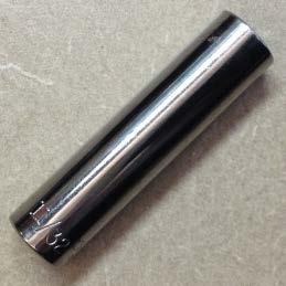
3 Recommended Tools 5/16 socket Crimper/cutters Zip ties 11/32 socket Alcohol or surface prep agent Rag 3/8 socket Amp/Molex pin extractor
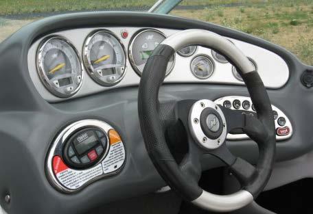
4 Procedure Overview Information about this kit: If you have determined that the Faria Gateway box is defective, there is no direct replacement for this device which will allow you to continue to operate with the original Gateway-driven gauges. Removal of the actual Gateway box is optional, but all original gauges must be removed. The Analog Gauge Installation Kit outlined in this manual will replace both Gateway box and Gateway gauges used in Nautique boats from model years 2003 to ) Remove old gauges from instrument panel 2) Install new gauges 3) Install analog gauge harness 4) Attach GPS antenna to bottom of dash pod 5) Install 25ft extension harness between dash and Gateway box at transom
 Stereo remote cable b) Keypad c) Analog Instruments connector (white")

5 Procedures 1) Remove old gauges from instrument panel From behind dash pod, disconnect a) Stereo remote cable b) Keypad c) Analog Instruments connector (white 12-pin) d) Cruise Control e) Faria bus cables Remove steering wheel and detach dash pod Remove all gauges except cruise control Disconnect Faria bus jumpers from between gauges


6 Procedures 2) Install new gauges - Use supplied hex nuts to attach each gauge to the instrument panel. Use caution when tightening black gauge brackets to avoid cracking the instrument panel. Tip: use a socket without a ratchet to tighten each nut. 5 gauge 5 gauge 2 gauge 8-32 nut 8-32 nut nut Cruise control


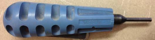
7 Procedures 3) Install analog gauge harness Using a pin extractor remove Perfect Pass tach wire from 12 way connector COR 5428 Gauge wiring harness Perfect Pass tach wire Insert tan engine temp wire in position 2 Insert PP tach wire in the 2way connector supplied with the new gauge harness, then insert gray wires back into position 3 Note: connector pinout is labeled from the wire insertion view, beginning at the notch for position #1 If you don t have a pin extractor, you can cut and splice the black and gray tach wires together to supply the tach signal to Perfect Pass and Tachometer Attach wires to gauges by sandwiching all ring terminals between two SS nuts. See schematic to locate each wire. Stackup top to bottom: SS nut Ring terminals SS nut Bracket
8


9 Procedures 4) Attach GPS antenna to bottom of dash pod Crimp three #10 ring terminals on GPS wires Prep the bottom surface of the dash pod with rubbing alcohol to remove contaminants. Remove adhesive backing and press antenna firmly into position as shown near the Speed gauge. The orientation and exact positon of the antenna is not critical, though it should be oriented with its bottom surface pointing directly upward to maximize performance. Install 1.5 x 1.5 VHB tape on bottom of GPS antenna

 Disconnect all wired connectors from Gateway box then connect the plugs from P2, P11, P13, and")


10 Procedures 5) Install 25ft extension harness a) Identify a suitable routing for the extension harness between the gateway box and the helm, away from hot or moving parts. b) Secure it to the boat with zipties 18 apart throughout its length. c) Disconnect all wired connectors from Gateway box then connect the plugs from P2, P11, P13, and P14 into the matching receptacles from the extension harness. Note: If old gateway box is removed from the boat when the new system is installed, be sure to plug the unused pitot tubes or remove the pickups and fill the holes to prevent leaks. Plugs connect these to new gauge harness at the helm Receptacles connect these to plugs from the old gateway box Gauge harness and extension harness interface - One 6way connector is reserved for 2006 & newer installations & newer model years only 2003 & 2005 model years Old Gateway plugs P2, P11, P13, & P14 connect to new extension harness receptacles Faria Bus(P3) and J1939(P6) are not used
11 Post Installation System Check An actual water test is recommended to ensure a fully functioning delivery to the customer. Perform this test with the engine running. Check Speedometer after GPS has locked in. The needle will hover around 4mph during satellite acquisition, then drop down to zero once acquired. If Perfect Pass is installed, use the speed adjust feature in the Perfect Pass display to match its speed to the new Speedometer. Check depth, air temp, and water temp gauge. Use the UP and DN arrows to toggle between air temp and water temp. Check Volt, Oil pressure, and Engine Temp gauges. Check Fuel and RPM gauge.
12 Troubleshooting Problem Possible Solutions Gauge does not function at all - Check for proper locations of gauge s ring terminals according to schematic - Check for 12v between gauge s Ignition and Ground posts - Check for loose connection to gauge s Signal post Gauges (multiple) do not function - Check orientation of Brown12-way Deutsch connector - Check boat harness connection to engine harness Speed readout more than 1.5mph different from actual speed - Make sure dial on back of gauge is set to 2 - Use speed adjust setting in Perfect Pass to sync it with the new analog GPS Speed gauge Speed readout shows 5mph, but boat is stationary - GPS defaults to 5mph until a satellite signal is locked. If no lock is achieved in reasonable time, try a different area, then replace antenna if unsuccessful Speedometer does not respond - Check for loose connections on the back of speedometer - Check wiring schematic for proper connections at the back of speedometer - Check for 12v between ignition and ground posts of speedometer Hours on tachometer (RPM gauge) LCD are less than ECM hours in Diacomm Hours on tachometer LCD are greater than ECM hours after many hours of operation - The new tachometer LCD begins hours at 0.0, regardless of engine s actual hours before installation. Only remedy is to connect Tachometer to 12v until timer catches up to ECM hours - No solution. Because tachometer hours are recorded by an independent clock when ignition power is on, it will deviate from the ECM s recorded hours. Always use Diacomm to read the boat s actual hours Tachometer is inaccurate or does not work at all - Make sure the dial on the back is set to 3 Engine Temp gauge does not work - Check location of Tan wire in the white 12-way connector behind the dash. It should connect to a Brown or Tan wire in the mating connector. - Check boat harness connection to engine harness Depth does not read when in favorable water, but Water and Air temp are ok - Check 2-way connection behind gauge - Check for damage to transducer in hull
Analog Gauge Installation Kit (Replaces Faria Gateway Gauge System)
") Cruise control Analog Gauge Installation Kit (Replaces 2003-2005 Faria Gateway Gauge System) PLUS Supplementary Instructions for 2006-2007 models with operational PerfectPass What s Included: 2 oil pressure
Cruise control Analog Gauge Installation Kit (Replaces 2003-2005 Faria Gateway Gauge System) PLUS Supplementary Instructions for 2006-2007 models with operational PerfectPass What s Included: 2 oil pressure
U L T I M A T E R A D A R / L A S E R D E F E N S E S Y S T E M
 S m a r t e r Q u i e t e r M o r e A c c u r a t e U L T I M A T E R A D A R / L A S E R D E F E N S E S Y S T E M Installation Manual PASSPORT 9500ci Comes Complete Front Radar Receiver Miniature weatherproof
BASIC TROUBLE SHOOTING (PERFECTPASS FOR MECHANICAL ENGINES) How PerfectPass Works
 How PerfectPass Works") BASIC TROUBLE SHOOTING (PERFECTPASS FOR MECHANICAL ENGINES) How PerfectPass Works Through the in-dash display the driver sets the desired boat speed or engine RPM depending upon which mode of operation
BASIC TROUBLE SHOOTING (PERFECTPASS FOR MECHANICAL ENGINES) How PerfectPass Works Through the in-dash display the driver sets the desired boat speed or engine RPM depending upon which mode of operation
Chevy INSTRUMENT CLUSTER CONNECTION KIT WIRING INFORMATION FOR A STOCK CHEVY CLUSTER GREY PINK S + FUEL TEMP S + LAMP LAMP HI BEAM
 WIRING INFORMATION FOR A STOCK 1955-56 CEVY CLUSTER 1955-56 Chevy Terminals and connectors are provided for installation to a stock 1955-56 dash cluster. Pigtail connections are provided for the instrument
DQT S GENX 6 INSTALLATION GUIDE
 DQT S GENX 6 INSTALLATION GUIDE VERSION: 1.1 DATE: 6/6/2017 PRESENTED BY: DQ TECHNOLOGIES Page 1 of 12 DQ Technologies, Inc., phone: 512.248.8324 - fax: 757.886.0831 - www.dqtech.com Contents Introduction...
Ford Mustang. Installation Manual
 1965 1966 Ford Mustang Installation Manual TABLE OF CONTENTS Welcome from the Team at Classic Instruments! 3 Mounting Gauges in New Bezel 4 3 3/8 Speedometer Wiring 6 3 3/8 Speedometer Wiring Diagram 6
INSTRUCTIONS. 20 Circuit Wiring Kit Instructions October 2009, Speedway Motors, Inc.
 1 MAIN FUSE PANEL The main fuse panel harness s designed to be mounted under the dash a the firewall in an area close to the steering column. The enclosed representation of the main dash harness shows
Rostselmash Torum 740
 Note: Indented items indicate parts included in an assembly listed above Quantity by Model Part Name/Description Part Number 740 Combine Kit Torum 740 4100762 1 Threaded Arm Assembly 2000311-2 1 Header
Dress White Standard Gauge
 187 Energy The Panther battery energy gauges allow you to determine the exact amount of charge remaining in your batteries. They are perfect for any boating, automotive, or industrial use, and can be used
AUTO GLIDE INSTALLATION GUIDE MANUAL A
 GLIDE INSTALLATION GUIDE MANUAL A TABLE OF CONTENTS.0 PRODUCT OVERVIEW 3-4. System Requirements 4.0 GLIDE MECHANICAL INSTALLATION 5-6. Auto Glide Key Pad Installation. Replacing Existing 3 LED Indicator
GPS AutoSteer System Installation Manual
 GPS AutoSteer System Installation Manual Supported Vehicles Case IH Vehicles Case 2577 Combines Case 2588 Combines Accuguide Ready PN: 602-0233-01-A LEGAL DISCLAIMER Note: Read and follow ALL instructions
EVINRUDE ICON GAUGES.
 EVINRUDE ICON 2 FROM THE MAKERS OF THE ULTIMATE OUTBOARD EVINRUDE ICON GAUGES. THE ULTIMATE GAUGES ARE HERE. FROM THE NO-NONSENSE BASIC SERIES TO THE FUNCTION- FILLED PRO SERIES, EVINRUDE ICON OFFERS BOATERS
Commander IS0128 ISO128E ECR# /04. Tachometer/ Engine Hourmeter
 Commander Tachometer/ Engine Hourmeter Analog Tachometer Digitally displays Hours Engine Has Been Run Fuel Level Other Features if Available: Fuel anagement Fuel Flow in GPH or LPH Total or Trip Fuel Used
EVINRUDE ICON GAUGES.
 EVINRUDE ICON 2 FROM THE MAKERS OF THE ULTIMATE OUTBOARD EVINRUDE ICON GAUGES. The ultimate gauges are here. FROM The no-nonsense BASIC SERIES TO ThE FUNCTIONfilled Pro Series, Evinrude ICON offers boaters
Owner s Manual. MG2000 Speedometer IS0211. for use with SmartCraft Tachometer
 Owner s Manual MG2000 Speedometer for use with SmartCraft Tachometer IS0211 rev. E ecr#6395 08/2006 4/5/05 Changes 12/21 Index Description Available Functions for display page 1 Default Screens page 1
Mustang. Installation Manual. Revision 11/16/10
 1967-1968 Mustang Installation Manual Revision 11/16/10 I Table of Contents TABLE OF CONTENTS...II WELCOME TO THE TEAM OF CLASSIC INSTRUMENTS!... III REMOVE ORIGINAL INSTRUMENT PANEL...1 DETERMINE SPEEDOMETER
Classic Instruments. Installation Manual
 Classic Instruments Installation Manual TABLE OF CONTENTS Welcome from the Team at Classic Instruments! 3 Mounting Gauges 4 4 Speedometer Wiring 5 4 Speedometer Wiring Diagram 5 16 Pulse Signal Generator
SPEED OF LIGHT PROTECTION
 Now With ESCORT Inc. 5440 West Chester Road West Chester OH 45069 800.433.3487 www.escortradar.com SPEED OF LIGHT PROTECTION S m a r t e r Q u i e t e r M o r e A c c u r a t e 2014 ESCORT Inc. Escort,
CAUTION: CAREFULLY READ INSTRUCTIONS BEFORE PROCEEDING
 Daytona Sensors LLC Engine Controls and Instrumentation Systems Installation Instructions for WEGO II Wide-Band Exhaust Gas Oxygen Sensor Interface Methanol Version CAUTION: CAREFULLY READ INSTRUCTIONS
Ford Mustang
 Classic Instruments 1965 1966 Ford Mustang Installation Manual Table of Contents Welcome from the Team at Classic Instruments!... 3 Mounting the Gauges... 4 3 3/8 Speedometer Wiring... 6 3 3/8 Speedometer
Quantity by Model an assembly listed above Early Models Late Models. Instruction Kit JD 9x00/9x
 Note: Indented items indicate parts included in Quantity by Model an assembly listed above Early Models Late Models Part Name/Description Part Number 9400/ 9500/ 9600/ 9400 9500 9600 9410 9510 9610 Instruction
GAUGES. Honda NMEA NMEA 2000 Speedometer. NMEA 2000 Gauge Kit NMEA Gauge Kit
 Honda NMEA 2000 The Honda NMEA 2000 tachometer and speedometer gauges display engine and vessel data received from up to five engines on the same NMEA 2000 backbone or bus. These gauges feature analog
INSTALLATION GUIDE Chevrolet Digital Dash Panel Part Number: DP6003 Year Series:
 INSTALLATION GUIDE Chevrolet Digital Dash Panel Part Number: DP6003 Year Series: 1967-1972 * Disconnect the battery before attempting any electrical work on your vehicle. * KIT COMPONENTS One (1) Digital
TL UNIVERSAL WIRING PROCEDURE
 UNIVERSAL WIRING PROCEDURE 3nov11jh TABLE OF CONTENTS 1 Control Kits 1.1. TIK10100 Universal Manual Hand Control 1.2. TIK10103 Universal Automatic Foot Control for Hydraulic Brakes 1.3. TIK10104 Universal
PerfectPass Digital Pro Installation Instructions
 PerfectPass Digital Pro Installation Instructions Step 1. Installation of Servo Motor Using the two provided hose clamps, loosely mount the servo motor on top of cooling water hose leading to drivers side
Operation Manual. For technical help please contact Livorsi Marine at or us at
 For technical help please contact Livorsi Marine at 4-5- or email us at info@livorsi.com This Operation Manual system is compatible with any Smartcraft, NMEA, J99 or Indmar engine. Livorsi Marine Inc 5
GPS AutoSteer System Installation Manual
 GPS AutoSteer System Installation Manual Supported Vehicles Agco Gleaner Combines R65 R66 R75 R76 PN: 602-0288-01-A LEGAL DISCLAIMER Note: Read and follow ALL instructions in this manual carefully before
Bayliner Model Year 2001
 Bayliner Marine Cluster Electrical & Functional Specification Page 1 of 49 Bayliner Model Year 2001 Electrical & Functional Specification Approvals: Sam Reaves Date: Don Hopkins Date: Wilt Rogers Date:
MSD 6AL Ignition Module w/ Rev Control - Installation Instructions
 MSD 6AL Ignition Module w/ Rev Control - Installation Instructions The below installation instructions work for the following products: MSD 6AL Ignition Module w/ Rev Control Please read through the instructions
Premium Gauge Panel Installation Instructions
 PontoonStuff, Inc. 115 Fremont Court Elkhart, IN 51 Tel: 877-295-9522 Premium Gauge Panel Installation Instructions Thank you for your purchase of the PontoonStuff.com Premium Gauge Panel This OEM quality
CLASSIC UPDATE WIRING KIT
 by Randy Irwin 1955-57 CLASSIC UPDATE WIRING KIT Randy Irwin - Technical Writer Randy has been involved in the Chevy parts business for over 25 years. He is a wizard at creating, making and modifying custom
Chevy Truck
 Classic Instruments 1967 1972 Chevy Truck Installation Manual Table of Contents Welcome from the Team at Classic Instruments!... 3 Remove the Stock / OEM Instrument Panel... 4 Instrument Cluster Wiring...
MODEL MVX-2011 TANK MOUNT SPEEDOMETER/TACHOMETER
 MODEL MVX-2011 TANK MOUNT SPEEDOMETER/TACHOMETER Wiring Diagram The MVX-2011 gauges will work on 2011-up Softail models with 5 gauges or 2012-up Dyna models with 5 gauges. It is a direct plug in on these
Classic Instruments Corvette. Installation Manual
 Classic Instruments 1963 1967 Corvette Installation Manual Table of Contents Welcome from the Team at Classic Instruments!... 3 Mounting the Gauges... 4 Gauge Cluster Wiring... 6 Gauge Cluster Wiring Diagram...
Remove 4 circled pins. Route wiring along dashed line. Remove the 2 9mm nuts and black retaining plate that secure extractor.
 2015 Ford Mustang Turn Signal Hood Kit Parts List: Quantity: Tool List: Bracket & pre-installed lamp 2 Flat head screwdriver Wiring harness 1 Phillips screwdriver PB-3660 Parts Bag 1 Ratchet & Socket set
AURORA SERIES GAUGES FUEL GAUGE SUGGESTED TOOLS AND MATERIALS. 3 3 /8 in (85.7 mm) PARTS LIST
 PARTS LIST") GAUGE INSTALLATION. Select mounting locations for the fuel gauge. 2. Cut a 2 /6 (52 mm) diameter hole for the gauge and test for proper fitmate. 3. Tighten the gauge with the enclosed Aurora Mounting Clamp
GAUGE INSTALLATION. Select mounting locations for the fuel gauge. 2. Cut a 2 /6 (52 mm) diameter hole for the gauge and test for proper fitmate. 3. Tighten the gauge with the enclosed Aurora Mounting Clamp
MF 9520 / 9540 / 9560, Challenger 540C / 560C
 Ag Leader Combine Installation Note: Indented items indicate parts included in an assembly listed above Part Name/Description Part Number 9520 Quantity by Model 9540 540C Parts Kit 2001312-69 1 1 1 Drill
Installation Manual. AutoSteer. Gleaner Combine. AutoGuide 2 Steer Ready. Supported Models A66 A76 R66 R76 S67 S77 PN: A
 Installation Manual AutoSteer Gleaner Combine AutoGuide 2 Steer Ready Supported Models A66 A76 R66 R76 S67 S77 PN: 602-0312-01-A LEGAL DISCLAIMER Note: Read and follow ALL Instructions in this manual carefully
UNIVERSAL GAUGE WIRE HARNESS
 2650-1797-00 UNIVERSAL GAUGE WIRE HARNESS For Installing Auto Meter Electric Speedometer, Tachometer, And Short Sweep Electric Oil Pressure, Water Temperature, Fuel Level, and Volt Meter Gauges. This harness
GPS Steering System Installation Manual
 GPS Steering System Installation Manual Supported Vehicles Challenger Massey Ferguson AGCO MT-645C, MT-645D MF-8650 DT-205B MT-655C, MT-655D MF-8660 DT-225B MT-665C, MT-665D MF-8670 DT-250B MT-675C, MT-675D
Classic Instruments Corvette. Installation Manual
 Classic Instruments 1963 1967 Corvette Installation Manual Table of Contents Welcome from the Team at Classic Instruments!... 3 Mounting the Gauges... 4 Gauge Cluster Wiring... 6 Gauge Cluster Wiring Diagram...
Chevrolet. Installation Manual
 1959 1960 Chevrolet Installation Manual TABLE OF CONTENTS Welcome from the Team at Classic Instruments!... 3 Mount Adapter Ring... 4 Mount New 4-5/8 Gauge in Center Gauge Pod... 4 Mount New 2-1/8 Gauges
Mustang. Installation Manual
 1967-1968 Mustang Installation Manual I Table of Contents TABLE OF CONTENTS... II WELCOME TO THE TEAM OF CLASSIC INSTRUMENTS!... III REMOVE ORIGINAL INSTRUMENT PANEL... 1 DETERMINE SPEEDOMETER SIGNAL...
CONTROL BOX. Wiring the control box into the vehicle. +12V
 CONTROL BOX Once the display panel is in place, mount the control box within the connecting cable's distance (approximately 3 feet) and secure to the underside of the dashboard. This case does not have
Flow Sensor
 NOTE: Indented items indicate parts included in an assembly listed above Part Name/Description Part Number Quantity Instruction Kit Metalfor 4101091 1 Quick reference sheet 2002831-36 1 Installation instructions
SUZUKI INSTRUMENTS. 4 Speedometer. 4 Tachometer. 2 Fuel Gauge
 SUZUKI INSTRUMENTS Economically priced, high quality instruments feature easy plug-in wiring connections, perimeterlighted dial, polished stainless steel bezels, contoured pointers and fog resistant glass
INSTALLATION INSTRUCTIONS
 2007-Current Jeep Wrangler 360º System for Aftermarket display (Kit # AVMS-3700v2) Please read thoroughly before starting installation and check that kit contents are complete. Items Included in the Kit:
Pilot. Owner s Manual IS0152
 OE A I PH KT Pilot I Owner s anual Pilot I isplays, peedometer in PH and Knots Trip Log Clock Voltmeter Air & urface Temp. igital epth ounder with eep and hallow water alarms, Keel offset Audible and Visual
CAUTION: CAREFULLY READ INSTRUCTIONS BEFORE PROCEEDING
 Daytona Sensors LLC Engine Controls and Instrumentation Systems Installation Instructions for Wide-Band Exhaust Gas Oxygen Sensor Interface CAUTION: CAREFULLY READ INSTRUCTIONS BEFORE PROCEEDING OVERVIEW
Nero 6600H/6601H. Installation Guide. Commercial Vehicle Productivity and Security. Antenna Configuration
 Commercial Vehicle Productivity and Security The 6600H/6601H is a versatile and economical GPS tracking beacon designed for fleet management needs in all commercial vehicles. The H designation in the model
Gentex Homelink Installation Instructions
 Gentex Homelink Installation Instructions Kit Contents: Item Qty Part Description 1 Number GENK-41 NVS Homelink Mirror GENK-42 NVS Homelink w/mood lights 1 of the GENK-45 NVS Homelink w/compass following
Mustang. Installation Manual
 1967-1968 Mustang Installation Manual Table of Contents WELCOME FROM THE TEAM AT CLASSIC INSTRUMENTS!... 3 REMOVE THE ORIGINAL INSTRUMENT PANEL... 4 WIRING DIAGRAM... 6 WIRING THE NEW INSTRUMENT CLUSTER...
Aftermarket Interface Module
 An ISO 9001:2008 Registered Company Aftermarket Interface Module (2015-2018 Ford Transit) AIM514-B High Side Solenoid type Coolant Valve Control AIM515-B Motor Reversing type Coolant Valve Control Introduction
Owner s Manual. IS0250a. ecr7106 9/2007
 TM Owner s Manual IS0250a ecr7106 9/2007 TABLE OF CONTENTS Part I: Introduction 3 Basic Operation 4 Part II: System Setup 6 Input Setup 6 Tank Setup 8 Depth Setup 9 Part III: Operating Instructions 10
INSTALLATION GUIDE Six Gauge Universal Digital Dash Panel Part Number: DP10002
 Made in America Lifetime Guarantee Thank you for purchasing this digital dash panel from Intellitronix. We value our customers! INSTALLATION GUIDE Six Gauge Universal Digital Dash Panel Part Number: DP10002
PIMP Ford 5.0 Harness Installation Manual. Part Number: PM-75
 PIMP Ford 5.0 Harness Installation Manual Part Number: PM-75 Ron Francis Wiring 200 Keystone Rd Suite 1 Chester, PA 19013 800-292-1940 www.ronfrancis.com Pre-Installation Notes: This system is designed
Thank you for purchasing the Craven Speed FlexPod Complete Gauge Pod Kit For R56, R58, R59, R60 with Refresh Engines (2011+)
") Thank you for purchasing the Craven Speed FlexPod Complete Gauge Pod Kit For R56, R58, R59, R60 with Refresh Engines (2011+) Before You Start Please read instructions completely before installing. These
Thank you for purchasing the Craven Speed FlexPod Complete Gauge Pod Kit For R56, R58, R59, R60 with Refresh Engines (2011+) Before You Start Please read instructions completely before installing. These
Parts List ILLUSTRATION #1
 Installation Instructions BR20 Rear Bumper Replacement Part Number 28295T 2015-2016 Ford F-150 2/4WD Do not attempt to install this product on any vehicle other than the one listed above! Parts List Item
Rugged Reliable Innovative Instruments for Automotive Commercial Industrial Performance Recreational Marine Military
 Aftermarket Catalog - 2019 We Have Moved - 75 North Frontage Road, Suite 106, North Stonington, CT 06359 Rugged Reliable Innovative Faria Beede Instruments, Inc. has been manufacturing gauges and instruments
Full Sweep Minor Gauge Wiring:
 Full Sweep Minor Gauge Wiring: Notes on Senders: Temp Hi match/vdo 150C: Normally used in Oil temp, 140 280F. Temp Low match/vdo120c: Normally used in water temp, 100 240F. To test the gauges work (oil,
GPS AutoSteer System Installation Manual
 GPS AutoSteer System Installation Manual Supported Vehicles New Holland Combines CR 9040 CX 9040 CR 9050 CX 9050 CR 9060 CX 9060 CR 9070 CX 9070 CR 9080 CX 9080 IntelliSteer Ready PN: 602-0231-01-A LEGAL
Gauges. MasterCraft Technical Training Vonore, Tennessee USA. A MasterCraft Technical Services Publication
 Gauges MasterCraft Technical Training Vonore, Tennessee USA A MasterCraft Technical Services Publication MasterCraft University 2008-2009 Gauges Page 1 Medallion Instrumentation Systems A Decade of Change
Classic Update Series
 J Clamps Two J-Clamps have been provided to retain the Cluster Kit Wiring in place (see photographs on pages 7 and ). Remove the original J-Clamps from the Cluster and replace with the two J-Clamps item
Classic Instruments Chevelle. Installation Manual
 Classic Instruments 1964 1965 Chevelle Installation Manual Table of Contents Welcome from the Team at Classic Instruments!... 3 Included Mounting Hardware... 4 Mounting Gauges... 5 Wiring Diagram... 6
Setup for using our speedometer with GPS sensor
 Setup for using our speedometer with GPS sensor Wiring: Speedometer red (1) power +12V Speedometer black (5) - ground Speedometer green (4) LED illumination (can be 12V) Speedometer blue (7) signal input,
Automotive Application ET01 Software Revision A 12/06
 Automotive Application ET01 Software Revision A 12/06 INTRODUCTION... 2 FUNCTIONAL DESCRIPTION... 3 INSTALLATION... 4 COMPONENT PLACEMENT... 4 PLUMBING AND WIRING... 5 MSBC OPERATION (ET-01)... 14 TIMED
IS0100. Technical Support and Troubleshooting Guide
 IS0100 Technical Support and Troubleshooting Guide IS0100 rev P ecn 10430 08/2016 For Technical Assistance contact Faria Beede Instruments - Customer Service Weekdays between 8:30 AM and 5:30 PM (EST)
Networkfleet 3500 Product Line Installation Guide
 Networkfleet 3500 Product Line Installation Guide Light/Medium Duty (L3500) Heavy Duty (H3500) Universal (U3500) www.networkcar.com/fleet Customer Care: (866) 227-7323 customercare@networkcar.com Table
ZONE BLOCKAGE AND FLOW MONITOR INSTALLATION MANUAL
 ZONE BLOCKAGE AND FLOW MONITOR INSTALLATION MANUAL Document revision: 1.1 Last revised: February 24, 2017 Zone Blockage and Flow Monitor Installation Manual 2017 Intelligent Agricultural Solutions. All
SP EVO-CHR4 (A)
") TIP SHEET Installation Tips for SP-502 + EVO-CHR4 (A) Remote Start / Alarm T1630 Chrysler 300 (2008-2011) Dodge Magnum (2008) Chrysler Town and Country (2008-2015) Dodge RAM (2009-2012) Dodge Challenger
TIP SHEET Installation Tips for SP-502 + EVO-CHR4 (A) Remote Start / Alarm T1630 Chrysler 300 (2008-2011) Dodge Magnum (2008) Chrysler Town and Country (2008-2015) Dodge RAM (2009-2012) Dodge Challenger
2010+ VW Mk6 2.0T Vent Boost Gauge Kit INSTALLATION GUIDE
 INSTALLATION GUIDE 2010+ VW Mk6 2.0T Vent Boost Gauge Kit Congratulations on your purchase of the AWE Tuning Vent Boost Gauge Kit for the 2010+ VW Mk6 2.0T. Exquisite build quality with industry leading
6 Gauge Box Set IS0333
 Caution 6 Gauge Box Set IS0 Rev. B ecr 882 9/202 Disconnect the battery during installation. Tighten nuts on the back clamp only slightly more than you can tighten with your fingers. Six inch-pounds of
GPS AutoSteer System Installation Manual
 GPS AutoSteer System Installation Manual John Deere Track Supported Models 8295RT 8320RT 8345RT PN: 602-0255-01-A LEGAL DISCLAIMER Note: Read and follow ALL instructions in this manual carefully before
INSTALLATION INSTRUCTIONS
 2007-Current Jeep Wrangler 360º System for Factory Display Radios (Kit # AVMS-3701) Please read thoroughly before starting installation and check that kit contents are complete. Items Included in the Kit:
INSTALLATION INSTRUCTIONS
 2007-Current Jeep Wrangler 360º System for Factory Display Radios (Kit # AVMS-3701v2) Please read thoroughly before starting installation and check that kit contents are complete. Items Included in the
MODEL MCL-2004(-R) TANK MOUNT SPEEDOMETER/TACHOMETER
 TANK MOUNT SPEEDOMETER/TACHOMETER") MODEL MCL-2004(-R) TANK MOUNT SPEEDOMETER/TACHOMETER Wiring Diagram The MCL-2004(-R) gauges will work on 2004-2011 models except 2011 Softail. It is a direct plug in on these models and requires no additional
MODEL MCL-2004(-R) TANK MOUNT SPEEDOMETER/TACHOMETER Wiring Diagram The MCL-2004(-R) gauges will work on 2004-2011 models except 2011 Softail. It is a direct plug in on these models and requires no additional
CAUTION: CAREFULLY READ INSTRUCTIONS BEFORE PROCEEDING
 Daytona Sensors LLC Engine Controls and Instrumentation Systems Installation Instructions for Wide-Band Exhaust Gas Oxygen Sensor Interface CAUTION: CAREFULLY READ INSTRUCTIONS BEFORE PROCEEDING OVERVIEW
Replacement Tach Board Manual
 Replacement Tach Board Manual 67-74 Dodge and Plymouth Cars that use electronics Internal to the tachometer. Real Time Engineering 19352 Hilton Rd. Springdale, AR 72764 (479) 756-3917 fax Rev8 www.rt-eng.com
GPS-50-2 GPS Speed and Bus Interface Module
 GPS Speed and Bus Interface Module IMPORTANT NOTE! When used to operate a cruise control, see the special mounting requirements on the bottom of page 6. setup/status switch Connection for GPS speed signal
Replace light bulb with the same number bulb as the one removed. White Wire: Connect to +12 Volt Lighting
 INSTALLATION INSTRUCTIONS SHORT SWEEP ELECTRIC GAUGES 2650-1079-00 Rev. C CAUTION FOR ALL GAUGE INSTALLATION (AMMETERS EXCLUDED) As a safety precaution, the +12V wire attached to the positive I (+) terminal
Chevy Truck
 Classic Instruments 1954 1955 Chevy Truck Installation Manual Table of Contents Welcome from the Team at Classic Instruments!... 3 Mounting Gauges... 4 4 5/8 Speedometer Wiring [no included tachometer]...
GM TRUCK BACKUP CAMERA INSTALLATION
 GM TRUCK 07-13 BACKUP CAMERA INSTALLATION Thank you for your purchase! These instructions are intended for the do-it-yourselfer who decides to install the camera without professional assistance. Keep in
UTV-1200 Multi Gauge for 2008 Yamaha Rhino
 IMPORTANT NOTE! This gauge has an hour meter and odometer preset option available only for the first 1.0 engine hour and 10 miles (16km). See ODO/HR PRESET for instructions. UTV-1200 Multi Gauge for 2008
SALEEN SPEEDLAB BOOST AND WATER TEMPERATURE GAUGE POD KIT
 = SALEEN SPEEDLAB BOOST AND WATER TEMPERATURE GAUGE POD KIT INSTALLATION MANUAL: 2005-09 Mustang 4.6L 3V P/N: 10-8002-C12000B KIT P/N: 10-2903-B11511* Saleen Performance, Inc. 1225 East Maple Rd. Troy,
GreenRoad Installation Document (GRID) Document Number: VWR10
 Document Number: VWR10") GreenRoad Installation Document (GRID) Document Number: VWR10 Chassis: Volvo B10BLE Version Created By Date Body: Wright Renown 1.0 JP 15/06/2011 Year: 1998/2000 Configuration: Single Deck Bus Adherence
GreenRoad Installation Document (GRID) Document Number: VWR10 Chassis: Volvo B10BLE Version Created By Date Body: Wright Renown 1.0 JP 15/06/2011 Year: 1998/2000 Configuration: Single Deck Bus Adherence
Conflicts: Vehicles with no sunroof or dual sunroof
 Toyota Sienna (Single Sunroof) 2012-8.5 Overhead Video Part Number: 00016-00125 -11 Accessory Code: ED9 Conflicts: Vehicles with no sunroof or dual sunroof General Applicability: 2011 Sienna SMR Kit Contents:
GPS AutoSteer System Installation Manual
 GPS AutoSteer System Installation Manual Supported Vehicles John Deere Sprayers 4700 4710 4720 Non-AutoTrac Ready PN: 602-0228-01-A LEGAL DISCLAIMER Note: Read and follow ALL instructions in this manual
REMOVAL OF FACTORY GAUGES ULTRA FLHT & FLHX
 MVX-8X04 gauge kit Thank you for purchasing the Dakota Digital MVX gauge kit for your Harley Davidson Touring bike. This kit is designed to be a direct plug in replacement for all touring models from 2004
INSTALLATION INSTRUCTIONS
 2007-Current Jeep Wrangler 360º System for Factory MyGig Display (Kit # AVMS-3701) Please read thoroughly before starting installation and check that kit contents are complete. Items Included in the Kit:
EXCELSIOR-HENDERSON MOTORCYCLE MANUFACTURING COMPANY 805 HANLON DRIVE BELLE PLAINE, MINNESOTA TELE: /FAX:
 All text, photographs, and illustrations in this handbook are based on the most current product information available at the time of publication. Product improvements or other changes may result in differences
IS0306 rev. B ecn /2013. MG Tachometer (NMEA2000 and J-1939) TACH 1760 RPM FUEL. Installation / User Manual.
 TACH 1760 RPM FUEL. Installation / User Manual.") IS0306 rev. B ecn 9055 11/2013 MG3000 - Tachometer (NMEA2000 and J-1939) TACH 1760 RPM FUEL Installation / User Manual www.faria-instruments.com IMPORTANT: This User s Guide outlines the functionality
IS0306 rev. B ecn 9055 11/2013 MG3000 - Tachometer (NMEA2000 and J-1939) TACH 1760 RPM FUEL Installation / User Manual www.faria-instruments.com IMPORTANT: This User s Guide outlines the functionality
VSM V-COUNT II are registered trademark of APEXS, Inc.
 Applied Expert Systems Inc. (APEXS, Inc.). 2003.All rights reserved VSM V-COUNT Vehicle Speed Sensor (VSS) Installation Guide VSM V-COUNT II are registered trademark of APEXS, Inc. VSS Installation Guide
Part Number Part Name/Description Instruction Kit JD 9x50/9x60/9x Flow Sensor
 ATTENTION If installing combine kit on a 9x70 series combine with factory-installed yield/moisture sensors, please take note of the special instructions in the Operational Checkout section (page 41) for
Classic Instruments Chevy. Installation Manual
 Classic Instruments 1957 Chevy Installation Manual Table of Contents Welcome from the Team at Classic Instruments!... 3 Mounting Gauges... 4 Speedo, Tach, Volt and Oil Pressure Gauge Wiring... 5 Speedo,
Classic Instruments Camaro. Installation Manual. Revised: January 6, 2015 Page 1
 Classic Instruments 1967 1968 Camaro Installation Manual Revised: January 6, 2015 Page 1 Contents Welcome from the Team at Classic Instruments!... 3 Remove Original Instrument Panel... 4 New Instrument
INSTALLATION GUIDE Chevrolet Impala/Caprice Digital Dash Panel Part Number: DP1208 Year Series: 1968
 Made in America Lifetime Guarantee Thank you for purchasing this instrument from Intellitronix. We value our customers! INSTALLATION GUIDE Chevrolet Impala/Caprice Digital Dash Panel Part Number: DP1208
Model: AEM14 Analog Engine Monitor
 Model: AEM14 Analog Engine Monitor Installation and Setup Manual Version 1 Table of Contents Monitor Overview DMK Engine Monitor Kit Section 1: Initial Setup 1.1 Internal Settings Switches Figure 1. AEM14
GPS Speedometer Module Part # and newer Sea Doo Models with Lake Temp Sensor
 Part # 9516-1997 and newer Sea Doo Models with Lake Temp Sensor Installation and Calibration Instructions Thank you for purchasing the Candoopro GPS Speedometer Module! The GPS Speedometer Module replaces
INSTALLATION MANUAL. Document revision: 1.3 Last revised: January 2, 2019
 INSTALLATION MANUAL Document revision: 1.3 Last revised: January 2, 2019 Recon SpreadSense Installation Manual 2017-19 Intelligent Agricultural Solutions. All Rights Reserved. Recon SpreadSense Installation
ENSURE THAT THE TEMP PROBE FITS YOUR OUTDRIVE BEFORE BEGINNING INSTALLATION.
 715 Center Street Grayslake IL 60030 P: 847-752-2700 F: 847-752-2415 E: info@livorsi.com Drive temp gauge installation instructions Model Number: DCSDT (color) The Livorsi drive temp gauge kit easily installs