VSM V-COUNT II are registered trademark of APEXS, Inc.
|
|
|
- Laureen Philippa Nicholson
- 5 years ago
- Views:
Transcription
1
2 Applied Expert Systems Inc. (APEXS, Inc.) All rights reserved VSM V-COUNT Vehicle Speed Sensor (VSS) Installation Guide VSM V-COUNT II are registered trademark of APEXS, Inc.

 Tie Wraps (5) In-Line Splice (2) Black Ground Wire (18AWG) Butt Splices (3) (26-22AWG or 24-20AWG) #8-10 Studs")
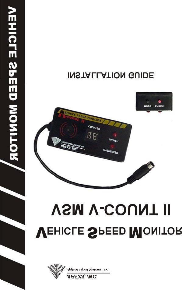
3 VSS Installation Guide INTRODUCTION The following instructions explain how to complete a Vehicle Speed Monitor (VSM) V-COUNT II VSS (Vehicle Speed Sensor) installation. VSS Installation is one of the two modes possible on the V-COUNT II Unit. Please see enclosed Installation Option Sheet. COMPONENTS The VSM V-COUNT II Unit (VSS Input) should come with all of the materials shown below. Please make sure you have all listed components before proceeding with the installation. VSM V-Count II Unit Wiring Harness Cable Red +12V Wire with Fuseholder (18AWG) Tie Wraps (5) In-Line Splice (2) Black Ground Wire (18AWG) Butt Splices (3) (26-22AWG or 24-20AWG) #8-10 Studs (3.5-5 mm. Whiter VSS Wire (18AWG) Fuses (2) (3AG 1-1/4 x 1/4",.25A, Slo- Blo) Velcro Tape (2)
4 Tools and Materials Needed The installation requires some or all the following tools and materials. Please make sure you have all necessary items before proceeding with the installation. Medium Philips Screwdriver Crimping Toll Pliers Electrical Drill with 2.5mm (7/64 ) Drill Bit Fuse Tap Multimeter (optional) INSTALLATION The instructions contained in the following sections provide guidelines for installation of the VSM V-COUNT II. Planning the Installation The Installation is similar to installing a vehicle stereo or vehicle alarm. The V-COUNT II requires three electrical inputs; +12 V, vehicle ground, and your vehicle s VSS signal. The steps required to install the V-COUNT II are: 1. Determine where to mount the V-COUNT II unit. 2. Locate and tap your VSS wire. 3. Locate and tap power (+12V from battery) and ground. 4. Connect the VSS Interface cable to the 3 main tap wires. 5. Mount the V-COUNT II in the vehicle. 6. Connect the V-COUNT II and go for a testdrive. WARNING: Installing the VSM V-COUNT II can be hazardous to both the installer and your vehicle s electrical system if not done by an experienced professional. This manual assumes you are aware of the inherent dangers of working in and around a vehicle and have a working understanding of electricity.
5 Wiring Diagram The diagram below provides an overall picture of the VSM-COUNT II VSS installation.
6 Step 1: Determine where to mount the VSM V-COUNT monitor Knowing where you are going to mount the VSM V-COUNT unit can help you make wiring decisions later on. For example, if your V-COUNT is near the fuse box it will be convenient to get un-switched +12V using a fuse tap connector. However, if your V-COUNT unit is on the other side of the vehicle it may be easier to find a lamp circuit, If the position of the unit is not critical, you may wish to move to the next step, and decide where to mount it after you ve tapped the three main electrical connections (+12V, Ground, VSS) NOTE: If you need ideas about where the display might be mounted, look at Step6: Mount the VSM V-COUNT unit in the Vehicle on page 8. Step 2: Locate and tap your VSS wire Contact the Maintenance/Service Department of the dealer from which the vehicle was purchased. The mechanic will have documentation indicating location of the VSS. This signal is connected to the speedometer. The V-COUNT VSS wire is be connected to the same signal. This connection will not prevent operation of the speedometer. VSS installation information is also available on the World Wide Web at Go to that web address and click on Rostra VSS & Tach Information System. Enter the full year and manufacturer of the vehicle. The information will specify a location number indicating where the wire can be found, and it will specify the wire color. NOTE: Some base model vehicles with manual transmission and no cruise control may not have a VSS module installed. Also, Vehicles manufactured before 1992 may not have VSS signal. Consult the service department if your vehicle has a cable driven speedometer, it may be possible for you to purchase a VSS pulse converter that can be installed to provide the VSS pulse. Use the inline splice to make the connection to the VSS wire as shown below. Select In-Line Splices to fit your VSS wire.
7 Step 3: Locate and tap power (+12) and ground The VSM V-COUNT II requires a constant (un-switched) +12 volts and has a negligible drain (10 ma) on the battery. You can obtain the +12V from several different places. Generally, you can easily obtain +12V from the fuse box using a fuse tap connector (not supplied) or the supplied in-line splice connectors to tap into a KNOWN circuit that does not involve safety related equipments (headlights, tail lights, air bag, etc.). Possible candidate wires include those from the cigarette lighter, dome light, glove compartment light, clock, tailgate light, or other convenience functions. After locating +12V, connect it to the red +12V wire (the one with the fuse holder) using the in-line splice as shown below. Do not install the fuse into the fuse holder until instructed to do so in step 4. If you are getting +12V from your fuse box, use a tap connector appropriate for your vehicle. A ground can be made by inserting the spade terminal under the head of the screw threaded into the vehicle chassis and then crimping the spade terminal onto the black ground wire, as shown below. Check that the screw is actually grounded using a multimeter before making the connection.
8 Step4: Connect the VSS Interface Cable to the three (3) Main Tap Wires Use the butt splice to connect the VSS Interface circuit input wires to your three main tap wires (+12V, Ground, VSS) by matching the wire colors. Red is used for +12V, black for the ground wire, brown for the VSS wire. Make sure the wiring harness extends to where you can plug the VSM V-COUNT II unit into it. Once the harness cable is connected, install the fuse into the fuse holder in the red (+12) tap wire. Step5: Choose the Correct Dip Switch Settings Because not all VSS signals are the same, you may need to change the default dip switch settings on the VSS in -line circuit. As a technical note, the switches have the following functions. Switch 1 is required if your VSS signal is a square wave which does not go to ground, Switch 2 AC couples the signal in and is used for sine wave VSS signals. Switch 3 improves the sensitivity of the AC coupled signals. Switch 4 turns on the LED test circuit.
9 Use this flow chart to determine the optimum dip switch setting. Note: You will need to test drive the vehicle and observe the red test LED which is enabled using switch 4. 0 (zero means the switch is off and 1 means switch is on.
 FACE OF DASHBOARD (Vertical Surfaces) Step 7: Connect the VSM V-COUNT Unit and Go for a Test Drive")

10 Step 6: Mount the VSM V-COUNT Unit in the Vehicle The following illustrations show possible mounting options for the unit. TOP OF DASHBOARD (Horizontal Surfaces) FACE OF DASHBOARD (Vertical Surfaces) Step 7: Connect the VSM V-COUNT Unit and Go for a Test Drive Connect the harness cable to the VSM V-COUNT unit cable as shown below. It is important to hold the cable as shown in order to achieve a secure connection. The connectors should be firmly pushed into place to make the connection. NOTE: For a more secure connection, we suggest tapping the two connectors together.
11 Once plugged in, the red TAMPER (LED) immediately will start flashing. This is NORMAL anytime the VSM V-COUNT has been disconnected from the power source of the vehicle for 5 minutes or more and re-connected. If the TAMPER (LED) remains off after connecting the V-COUNT, check both the +12V and ground connection. It is also possible that the unit may alarm unexpectedly during an initial test drive, which can be caused by incorrect calibration along with the maximum speed being set. Consult the calibration section of the VSM V-COUNT User s Guide for the V-COUNT for instructions on calibrating the unit. APPENDIX 1: TROUBLESHOOTING If your VSM V-COUNT II is not responding the way we expected, consult the following checklist to help you identify the cause of the problem. Make sure the unit has been calibrated correctly. Check the calibration section of the VSM V-COUNT II unit User s manual The switch setting on the VSS Interface circuit is not correct. Go to step 5 Double check your power and ground connection using a multimeter. The red TAMPER (LED) immediately will start flashing. This is NORMAL anytime the VSM V-COUNT has been disconnected from the power source for 5 minutes or more and re-connected. Make sure the VSS wire is correct. If the red test LED of the VSS Interface circuit does not flash at low speeds, you may not have the correct wire (switch 4 must be on to enable the test circuit). The following other method can be used to see if you have the correct wire. A voltmeter can be used on square wave signals to verify the 2 DC levels when the vehicle must be running and driven very slowly (about 2MPH/5KPH) to detect this change. Check with your local vehicle dealership service/maintenance department to make sure the vehicles make and model is equipped with a VSS signal.
DriveRight VSS Installation Guide
 DriveRight VSS Installation Guide Product # 8155VSS, 8155VF, 8160VSS, 8160VF Product Number: 8155VSS, 8155VF, 8160VSS, 8160VF Davis Instruments Part Number: 7395-062 DriveRight VSS Installation Guide Rev.
GW-CRUISE Cruise Control Vanagon [84-91]
![GW-CRUISE Cruise Control Vanagon [84-91]](/thumbs/78/76865696.jpg "GW-CRUISE Cruise Control Vanagon [84-91]") Driving without cruise control on a long trip can be tiring. Update your vehicle with some modern convenience with this easy to install cruise control kit. Tools Needed Phillips screwdriver #2 Electric
Driving without cruise control on a long trip can be tiring. Update your vehicle with some modern convenience with this easy to install cruise control kit. Tools Needed Phillips screwdriver #2 Electric
General-Duty & Heavy-Duty Installation Manual
 General-Duty & Heavy-Duty Installation Manual E Product # 8126GD, 8126HD CONTENTS Introduction........................................................ 1 Components.....................................................
General-Duty & Heavy-Duty Installation Manual
 Distributed by MicroDAQ.com, Ltd. www.microdaq.com (603) 746-5524 General-Duty & Heavy-Duty Installation Manual Product # 8156GD, 8156HD &217(176 Introduction........................................................
IT IS IMPORTANT THAT YOU OBTAIN THE CORRECT INFORMATION FOR YOUR VEHICLE, OR DAMAGE TO THE WIRING SYSTEM COULD OCCUR.
 Instructions for Universal Harness PRINT THESE INSTUCTIONS Gentex Mirror Installation Instructions Provided by www.rearviewautomirrors.com These instructions have been prepared to provide you with details
30140 F5 Dual Fan Controller
 30140 F5 Dual Fan Controller 1 2501 Ludelle Street Fort Worth, Texas 76105 817-244-6212 Phone 817-244-4024 Fax 888-350-6588 Sales 800-423-9696 Tech E-mail: painless@painlessperformance.com Web: www.painlessperformance.com
TIP SHEET T0937. Installation Tips For RS00/PS00 + ADS-TBSL-PL + SPDT
 Installation Tips For RS00/PS00 + ADS-TBSL-PL + SPDT TIP SHEET T0937 Thank you for purchasing your remote start from MyPushcart.com - an industry leader in providing remote starts to do-it-yourself installers
INSTALLATION GUIDE Chevrolet Digital Dash Panel Part Number: DP6003 Year Series:
 INSTALLATION GUIDE Chevrolet Digital Dash Panel Part Number: DP6003 Year Series: 1967-1972 * Disconnect the battery before attempting any electrical work on your vehicle. * KIT COMPONENTS One (1) Digital
RECOMMENDED TOOLS PERSONAL & VEHICLE PROTECTION SAFETY GLASSES
 PART NUMBER: 250-9631 GENERAL APPLICABILITY THIS CRUISE WAS TESTED AND VERIFIED ON: ALL MODELS (AT/MT) RECOMMENDED TOOLS PERSONAL & VEHICLE PROTECTION SAFETY GLASSES KIT CONTENTS/SERVICE PARTS ITEM QTY
Installation Instructions
 Installation Instructions for EVS II Security and Keyless Entry Systems Note: It is recommended that this installation take place prior to rustproofing. The individual delivering the vehicle should review
Security and Keyless Entry Installation Guide ca 1051
 PROFESSIONAL SERIES Security and Keyless Entry Installation Guide ca 1051 ca1051 rev B. 2011 Audiovox Electronics Corporation. All rights reserved. 1 Table of Contents Before You Begin... 3 Wire Connection
USB Charge Port Installation Instructions
 USB Charge Port Installation Instructions Lifetime Technical Support support@logolites.com 770-476-7322 www.logolites.com Manual 100-0014C Thank you for purchasing a Logo Lites USB Charge Port! USB Charge
RECOMMENDED TOOLS PERSONAL & VEHICLE PROTECTION SAFETY GLASSES
 PART NUMBER: 250-9545 GENERAL APPLICABILITY THIS CRUISE WAS TESTED AND VERIFIED ON:2.7,3.3, 3.5, 5.0 FORD F-150 RECOMMENDED TOOLS PERSONAL & VEHICLE PROTECTION SAFETY GLASSES KIT CONTENTS/SERVICE PARTS
RECOMMENDED TOOLS PERSONAL & VEHICLE PROTECTION SAFETY GLASSES
 PART NUMBER: 250-9625 GENERAL APPLICABILITY THIS CRUISE WAS TESTED AND VERIFIED ON: ALL MODELS RECOMMENDED TOOLS PERSONAL & VEHICLE PROTECTION SAFETY GLASSES KIT CONTENTS/SERVICE PARTS ITEM QTY DESCRIPTION
RECOMMENDED TOOLS PERSONAL & VEHICLE PROTECTION SAFETY GLASSES
 PART NUMBER: 250-9627 GENERAL APPLICABILITY THIS CRUISE WAS TESTED AND VERIFIED ON: ALL MODELS (AT/MT) RECOMMENDED TOOLS PERSONAL & VEHICLE PROTECTION SAFETY GLASSES KIT CONTENTS/SERVICE PARTS ITEM QTY
Installation Tips for your Crimestopper/ProStart Remote Start system (add-on for GM vehicles) v1.02 updated 1/16/2013
 v1.02 updated 1/16/2013") Installation Tips for your Crimestopper/ProStart Remote Start system (add-on for GM vehicles) v1.02 updated 1/16/2013 Thank you for purchasing your remote start from MyPushcart.com - an industry leader
Installation Tips for your Crimestopper/ProStart Remote Start system (add-on for GM vehicles) v1.02 updated 1/16/2013 Thank you for purchasing your remote start from MyPushcart.com - an industry leader
TIP SHEET. Installation Tips for your RS IB-MUX / PKUMUX (D) + SPDT T1205 v1.2 4/3/14. 1 P a g e
 + SPDT T1205 v1.2 4/3/14. 1 P a g e") Installation Tips for your RS-150 + IB-MUX / PKUMUX (D) + SPDT T1205 v1.2 4/3/14 TIP SHEET Thank you for purchasing your remote start from MyPushcart.com - an industry leader in providing remote starts
Installation Tips for your RS-150 + IB-MUX / PKUMUX (D) + SPDT T1205 v1.2 4/3/14 TIP SHEET Thank you for purchasing your remote start from MyPushcart.com - an industry leader in providing remote starts
RECOMMENDED TOOLS PERSONAL & VEHICLE PROTECTION SAFETY GLASSES
 HYUNDAI ACCENT 2012-18 /ELANTRA 2012-16 / KIA RIO 2012-2018 KIO FORTE 2014-18 PART NUMBER: 250-1862 GENERAL APPLICABILITY THIS CRUISE WAS TESTED AND VERIFIED ON: (AT/MT) VEHICLES RECOMMENDED TOOLS PERSONAL
HA PRO INSTALLERʼS MANUAL. HA-008 v3. User s/installer s Manual
 HA-008 v3 HA - 280 PRO User s/installer s Manual INSTALLERʼS MANUAL Manufacturer: COMMERCIAL ELECTRONICS 264 HAYDONS ROAD, WIMBLEDON, LONDON SW19 8TT. UK TEL: +44 020 8404 7105 FAX: +44 020 8404 7104 http://www.hawkcaralarm.com
Installation Tips for RS1 + EVO-RIDE + SPDT. *(reglar key, automatic transmission vehicles ONLY)*
*") Installation Tips for RS1 + EVO-RIDE + SPDT TIP SHEET T1235 *(reglar key, automatic transmission vehicles ONLY)* Thank you for purchasing your remote start from MyPushcart.com - an industry leader in providing
Installation Tips for RS1 + EVO-RIDE + SPDT TIP SHEET T1235 *(reglar key, automatic transmission vehicles ONLY)* Thank you for purchasing your remote start from MyPushcart.com - an industry leader in providing
Camaro Camaro
 Important facts about this kit. 1. The dash panel used in this picture is used by permission of Covan's Classic. We Make Wiring Easy! 2. This kit requires some modification to your original under dash
TIP SHEET T0937. Installation Tips for RS00 + Passlock-sl2(4) + SPDT
 + SPDT") Installation Tips for RS00 + Passlock-sl2(4) + SPDT TIP SHEET T0937 Chevrolet (Astro 1998-2005) (Avalanche 2002-2006) (Blazer 1998-2005) (Express Van 1998-2007) (Impala 2000-2005) (Monte Carlo 2000-2005)
Installation Tips for RS00 + Passlock-sl2(4) + SPDT TIP SHEET T0937 Chevrolet (Astro 1998-2005) (Avalanche 2002-2006) (Blazer 1998-2005) (Express Van 1998-2007) (Impala 2000-2005) (Monte Carlo 2000-2005)
Installation Tips - (Crimestopper RS1/RS2) & (Fortin EVO-ALL 5): *regular key & automatic transmission only*
 & (Fortin EVO-ALL 5): *regular key & automatic transmission only*") Installation Tips - (Crimestopper RS1/RS2) & (Fortin EVO-ALL 5): TIP SHEET T3385f, T3413f *regular key & automatic transmission only* Thank you for purchasing your remote start from MyPushcart.com - an
Installation Tips - (Crimestopper RS1/RS2) & (Fortin EVO-ALL 5): TIP SHEET T3385f, T3413f *regular key & automatic transmission only* Thank you for purchasing your remote start from MyPushcart.com - an
RECOMMENDED TOOLS PERSONAL & VEHICLE PROTECTION SAFETY GLASSES
 PART NUMBER: 250-9625 GENERAL APPLICABILITY THIS CRUISE WAS TESTED AND VERIFIED ON: ALL MODELS RECOMMENDED TOOLS PERSONAL & VEHICLE PROTECTION SAFETY GLASSES KIT CONTENTS/SERVICE PARTS ITEM QTY DESCRIPTION
CP 634 DELUXE 4-CHANNEL KEYLESS ENTRY SYSTEM
 CP 634 DELUXE 4-CHANNEL KEYLESS ENTRY SYSTEM Installation And Operation Manual MEGATRONIX VAN NUYS, CA U.S.A. CP634 1 REMOTE CONTROL CONVENIENT SYSTEM INSTALLATION & OPERATION INSTRUCTIONS INTRODUCTION
MM1 Installation Instructions
 MM1 Installation Instructions PROFESSIONAL INSTALLATION STRONGLY RECOMMENDED Installation Precautions: Roll down window to avoid locking keys in vehicle during installation Avoid mounting components or
RECOMMENDED TOOLS PERSONAL & VEHICLE PROTECTION SAFETY GLASSES
 HYUNDAI ACCENT 2010- /ELANTRA 2012- / KIA RIO 2012- PART NUMBER: 250-9628-NS GENERAL APPLICABILITY THIS CRUISE WAS TESTED AND VERIFIED ON: (AT/MT) VEHICLES RECOMMENDED TOOLS PERSONAL & VEHICLE PROTECTION
BX8848 Installation Instructions 4 Diode Wiring Kit For Motorhomes With Red Tail Lights
 For Motorhomes With Red Tail Lights WARNG: Incorrect wiring may result in blown fuses, damaged wiring, fire, or bodily injury. Blue Ox recommends installation of this kit by a trained professional. Blue
RECOMMENDED TOOLS PERSONAL & VEHICLE PROTECTION SAFETY GLASSES
 PART NUMBER: 250-9618 AUTOMATIC TRANSMISSION 250-9619 MANUAL TRANSMISSION GENERAL APPLICABILITY THIS CRUISE WAS TESTED AND VERIFIED ON: CHEVY SONIC/ SPARK (ALL MODELS) RECOMMENDED TOOLS PERSONAL & VEHICLE
Superlift TruSpeed Speed Sensor Calibrator For Most Ford Trucks and SUVs 1992-Present INSTALLATION INSTRUCTIONS
 FORM #33001.06-121703 PRINTED IN U.S.A. PAGE 1 OF 11 INTRODUCTION Superlift TruSpeed Speed Sensor Calibrator For Most Ford Trucks and SUVs 1992-Present INSTALLATION INSTRUCTIONS SUPERLIFT SUSPENSION SYSTEMS
CSI-300 Installation Instructions
 CSI-300 Installation Instructions Kit Contents Installation Precautions: Roll down window to avoid locking keys in vehicle during installation Avoid mounting components or routing wires near hot surfaces
Gen INSTALLATION MANUAL
 Gen 2 INSTALLATION MANUAL READ THIS FIRST Installation of this system should be carried out by qualified persons familiar with the general installation of law enforcement electronics commonly installed
Throttle Sensitivity Booster
 U 1 New version allows for optional control switch. See page 4 for details. Throttle Sensitivity Booster Apps Booster 1057730 (Manual trans only) Vehicle / Year 1998.5-2003 Dodge Cummins DO NOT INSTALL
Installation Instructions
 patent pending Portable Proportional Braking System Installation Instructions Part number 9400 Towing and Suspension Solutions ROADMASTER, Inc. 6110 NE 127th Ave. Vancouver, WA 98682 800-669-9690 Fax 360-735-9300
Part Number DP6003 Chevy Truck Digital Dash YEARS 67-72
 Part Number DP6003 Chevy Truck Digital Dash YEARS 67-72 KIT COMPONENTS: One (1) Digital Circuit Board One (1) Smoked Acrylic See-Through Lens *Peel off protective covering from both sides of lens attached
Ford Mustang. Installation Manual
 1965 1966 Ford Mustang Installation Manual TABLE OF CONTENTS Welcome from the Team at Classic Instruments! 3 Mounting Gauges in New Bezel 4 3 3/8 Speedometer Wiring 6 3 3/8 Speedometer Wiring Diagram 6
SCION tc SECURITY (V5) Preparation
 Preparation") Preparation Part Number: PT398-21070 Kit Contents Item # Quantity Reqd. Description 1 1 2 1 GBS ECU Hardware Bag Contents Item # Quantity Reqd. Description 1 1 V5 Security ECU 2 1 ECU Mounting Bracket
Preparation Part Number: PT398-21070 Kit Contents Item # Quantity Reqd. Description 1 1 2 1 GBS ECU Hardware Bag Contents Item # Quantity Reqd. Description 1 1 V5 Security ECU 2 1 ECU Mounting Bracket
Installation Tips for your RS-1 + Honda-SL3 (1.b) Remote starter Honda: ( FIT), ( Pilot), ( Ridgeline) Acura: ( MDX)
 Remote starter Honda: ( FIT), ( Pilot), ( Ridgeline) Acura: ( MDX)") Installation Tips for your RS-1 + Honda-SL3 (1.b) Remote starter Honda: ( 06-08 FIT), ( 05-08 Pilot), ( 06-13 Ridgeline) Acura: ( 03-06 MDX) TIP SHEET T0777 Thank you for purchasing your remote start from
Installation Tips for your RS-1 + Honda-SL3 (1.b) Remote starter Honda: ( 06-08 FIT), ( 05-08 Pilot), ( 06-13 Ridgeline) Acura: ( 03-06 MDX) TIP SHEET T0777 Thank you for purchasing your remote start from
TIP SHEET T2352, T3396. Installation Tips for RS1 + EVO-ALL 1-BUTTON REMOTE STARTER FOR: Acura RDX PUSH-TO-START / AUTOMATIC
 Installation Tips for RS1 + EVO-ALL 1-BUTTON REMOTE STARTER FOR: Acura RDX 2013-2015 PUSH-TO-START / AUTOMATIC TIP SHEET T2352, T3396 Thank you for purchasing your remote start from MyPushcart.com - an
GM TRUCK BACKUP CAMERA INSTALLATION
 GM TRUCK 07-13 BACKUP CAMERA INSTALLATION Thank you for your purchase! These instructions are intended for the do-it-yourselfer who decides to install the camera without professional assistance. Keep in
Detroit Speed, Inc. RS Electric Headlight Door Kit 1969 Camaro P/N: (3)
") Detroit Speed, Inc. RS Electric Headlight Door Kit 1969 Camaro P/N: 122001 (3) (1) (2) (5) (4) Figure 1 Item QTY Description 1 1 LH actuator w/bracket and linkage 2 1 RH actuator w/bracket and linkage
Detroit Speed, Inc. RS Electric Headlight Door Kit 1969 Camaro P/N: 122001 (3) (1) (2) (5) (4) Figure 1 Item QTY Description 1 1 LH actuator w/bracket and linkage 2 1 RH actuator w/bracket and linkage
ONBOARD AIR SYSTEM FOR ALL VEHICLES APPLICATIONS
 ONBOARD SYSTEM FOR ALL VEHICLES APPLICATIONS Thank you and congratulations on the purchase of a Pacbrake onboard air system. Please read the manual prior to starting to ensure you can complete the installation
Installation Guide and User s Manual
 Installation Guide and User s Manual Version 1 Table of Contents 1. Introduction...1 1.1 Notes and warnings...1 2. Installation/Setup...2 2.1 LCD monitor...2 2.2 Monitor inputs...2 3. Monitor wiring harness...3
CARM INTERNATIONAL TOWING MODULES
 CARM INTERNATIONAL TOWING MODULES (TA100/200 Instructions Revision = 1) Each Towing Module (if ordered with Loom Pack) is shipped with: A/ These instructions B/ 1 x Towing Control Module C/ 1 x high current
Installation Tips for RS4/RS7 + EVO-ALL (NIS 3.c) + 2 diodes
 + 2 diodes") Installation Tips for RS4/RS7 + EVO-ALL (NIS 3.c) + 2 diodes TIP SHEET T3093 + T3103 FOR: NISSAN ( 09-14 Cube), ( 11-14 Juke), & ( 07-11 Versa) automatic, regular key vehicles Thank you for purchasing
Installation Tips for RS4/RS7 + EVO-ALL (NIS 3.c) + 2 diodes TIP SHEET T3093 + T3103 FOR: NISSAN ( 09-14 Cube), ( 11-14 Juke), & ( 07-11 Versa) automatic, regular key vehicles Thank you for purchasing
RECOMMENDED TOOLS PERSONAL & VEHICLE PROTECTION SAFETY GLASSES
 MITSUBISHI MIRAGE 2013- PART NUMBER: 250-9633 GENERAL APPLICABILITY ALL MODELS RECOMMENDED TOOLS PERSONAL & VEHICLE PROTECTION SAFETY GLASSES KIT CONTENTS/SERVICE PARTS ITEM QTY DESCRIPTION PART# 1 1 CRUISE
RECOMMENDED TOOLS PERSONAL & VEHICLE PROTECTION SAFETY GLASSES
 PART NUMBER: 250-9632 GENERAL APPLICABILITY SUBARU IMPREZA (MT/AT) RECOMMENDED TOOLS PERSONAL & VEHICLE PROTECTION SAFETY GLASSES KIT CONTENTS/SERVICE PARTS ITEM QTY DESCRIPTION PART# 1 1 CRUISE CONTROL
GROM Interface Installation into Nissan and Infiniti cars using NIS2 vehicle specific harness
 GROM Interface Installation into Nissan and Infiniti cars using NIS2 vehicle specific harness Tools needed 1. The wire crimp tool 2. Panel trim removal tool (optional) 3. Philips screwdriver Picture 1:
SAFETY-- SECURITY-- SIMPLICITY! TM
 T3 Vehicle Security Tracker Installation Guide SAFETY-- SECURITY-- SIMPLICITY! TM 911Tracker.com T3 Vehicle Security Tracker Installation Guide COPYRIGHTS 2017 911Tracker All rights reserved. 911Tracker
INSTALLATION GUIDE Chevrolet Digital Dash Panel Part Number: DP6002 YEAR SERIES:
 Intelligent Electronics INSTALLATION GUIDE Chevrolet Digital Dash Panel Part Number: DP6002 YEAR SERIES: 1964-1966 * Disconnect the battery before attempting any electrical work on your vehicle. * KIT
CSI-400 Installation Instructions
 CSI-400 Installation Instructions Kit Contents Installation Precautions: Roll down window to avoid locking keys in vehicle during installation Avoid mounting components or routing wires near hot surfaces
ATTENTION. Custom Dynamics UTV Turn Signal Kit Installation Instructions
 Custom Dynamics UTV Kit Installation Instructions We thank you for purchasing the Custom Dynamics UTV LED Kit. Our products utilize the latest technology and high quality components to ensure you the most
Installation Instructions
 Instructions Created by an: DIY Underhood LED Lighting Kit (SKU# DIY-E-UHLK) Installation Instructions NOTICE: This Under Hood Light Kit was installed on a 2002 Toyota Tacoma. However, these instructions
TOYOTA YARIS KEYLESS ENTRY SYSTEM
 TOYOTA YARIS 2011 - KEYLESS ENTRY SYSTEM Part Number: 00016-32901 Accessory Code: KE1 Conflicts Not for installation in vehicles equipped with factory installed keyless entry. Kit Contents Item # Quantity
Installation Tips for your Remote Start system (for Toyota Camry & Prius C, ) Crimestopper RS0+ EVO-ALL T3468 rev#1.
 Crimestopper RS0+ EVO-ALL T3468 rev#1.") Installation Tips for your Remote Start system (for Toyota Camry & Prius C, 2012-2014) Crimestopper RS0+ EVO-ALL T3468 rev#1.1 1/22/2015 Thank you for purchasing your remote start from MyPushcart.com -
Installation Tips for your Remote Start system (for Toyota Camry & Prius C, 2012-2014) Crimestopper RS0+ EVO-ALL T3468 rev#1.1 1/22/2015 Thank you for purchasing your remote start from MyPushcart.com -
INSTALLATION GUIDE Chevrolet Digital Dash Panel Part Number: DP6004 Year Series:
 INSTALLATION GUIDE Chevrolet Digital Dash Panel Part Number: DP6004 Year Series: 1973-1987 * Disconnect the battery before attempting any electrical work on your vehicle. * KIT COMPONENTS Three (3) Digital
ECT Display Driver Installation for AP2 Module
 ECT Display Driver Installation for AP2 Module Overview The ECT Display Driver is a small module with a removable wire harness that mounts behind the driver's foot well cover. All wiring connections are
Detroit Speed, Inc. RS Electric Headlight Door Kit 1968 Camaro P/N: (3)
") Detroit Speed, Inc. RS Electric Headlight Door Kit 1968 Camaro P/N: 122002 (3) (1) (2) (5) (4) Figure 1 Item QTY Description 1 1 LH Actuator w/bracket and Linkage 2 1 RH Actuator w/bracket and Linkage
Detroit Speed, Inc. RS Electric Headlight Door Kit 1968 Camaro P/N: 122002 (3) (1) (2) (5) (4) Figure 1 Item QTY Description 1 1 LH Actuator w/bracket and Linkage 2 1 RH Actuator w/bracket and Linkage
Remote Keyless Entry Installation Guide ca 2051
 PROFESSIONAL SERIES Remote Keyless Entry Installation Guide ca 2051 ca2051 rev B. 2011 Audiovox Electronics Corporation. All rights reserved. 1 Table of Contents Before You Begin... 3 Wire Connection Guide...
Installation Tips for your Remote Start/Keyless Entry (for Ford Vehicles) v3.3 Updated 1/13/2013
 v3.3 Updated 1/13/2013") Installation Tips for your Remote Start/Keyless Entry (for Ford Vehicles) v3.3 Updated 1/13/2013 Thank you for purchasing your remote start from MyPushcart.com - an industry leader in providing remote
Installation Tips for your Remote Start/Keyless Entry (for Ford Vehicles) v3.3 Updated 1/13/2013 Thank you for purchasing your remote start from MyPushcart.com - an industry leader in providing remote
UNPACK AND IDENTIFY THE FOLLOWING PARTS.
 SUT-250-M2 ASSEMBLY REQUIREMENTS *Torque all T-bolt nuts to 35-40 foot pounds. *Check all lights before towing. *Tire pressure not to exceed recommendation on serial tag. *Re-torque wheel nuts after first
LEXUS CT 200h 2011 TVIP V2 PREPARATION
 PREPARATION Part #: PT398-76110 Conflicts: Kit Contents GBS ECU V2 Harness GBS ECU Bracket Nut Microphone Foam Tape Wire Tie x1 x1 x1 x1 x1 x2 x15 08190-0C820 08192-6C820 Window Label Owner s Guide PT398-60084
INSTALLATION MANUAL AP60B INSTALLATION MANUAL
 INSTALLATION MANUAL 2. TOOLS REQUIRED The following is a list of tools required to properly install the cruise control. While this unit may be installed without some of the tools listed, it is recommended
Turn Signal Kit Installation Instructions for Model A Fords & Other Antique Vehicles
 Turn Signal Kit Installation Instructions for Model A Fords & Other Antique Vehicles Lifetime Technical Support support@logolites.com 770-476-7322 www.logolites.com Manual 100-0005N Thank you for purchasing
RS4 / RS7 + (4) + SPDT
 + SPDT") TIP SHEET Installation Tips for RS4 / RS7 + Honda-SL3 (4) + SPDT + Diode x2 T0776, T0731 Honda: ( 08-12 Accord), ( 12-13 Civic), 12-13 CRV), ( 11-13 Odyssey), ( 09-13 Pilot) Acura: ( 09-13 TSX) Thank you
TIP SHEET Installation Tips for RS4 / RS7 + Honda-SL3 (4) + SPDT + Diode x2 T0776, T0731 Honda: ( 08-12 Accord), ( 12-13 Civic), 12-13 CRV), ( 11-13 Odyssey), ( 09-13 Pilot) Acura: ( 09-13 TSX) Thank you
Informational Distribution List:
 Technical Bulletin 2017 Southern Technologies Corporation (STC). All rights reserved. Bulletin Number: TB-2017198-BW01 Date Published: 07/17/2017 Summary: Instructions for mounting, aligning and setting
*(reglar key vehicles ONLY)* Read the entire installation manual. There are several safety tips in there to know before you start
* Read the entire installation manual. There are several safety tips in there to know before you start") Installation Tips for RS4 + EVO-RIDE + SPDT TIP SHEET T2519 2009-2011 Ford Crown Victoria 2009-2012 Ford E-150 2009 Ford E-150 Econoline Club Wagon 2008-2010 Ford E-250 2010 Ford E-250 Econoline 2010 Ford
Installation Tips for RS4 + EVO-RIDE + SPDT TIP SHEET T2519 2009-2011 Ford Crown Victoria 2009-2012 Ford E-150 2009 Ford E-150 Econoline Club Wagon 2008-2010 Ford E-250 2010 Ford E-250 Econoline 2010 Ford
Conflicts: Vehicles with a sunroof
 Toyota 4Runner Non/MR 2010-10.2 Overhead Video Part Number: 00016-00110; Fit Kit -00110-15, Beige 00016-00120; Fit Kit -00120-15, Gray Accessory Code: ED6 Conflicts: Vehicles with a sunroof Kit Contents:
FORM # PRINTED IN U.S.A. PAGE 1 OF 11
 FORM #33002.08-010507 PRINTED IN U.S.A. PAGE 1 OF 11 SUPERLIFT SUSPENSION SYSTEMS 300 Huey Lenard Loop Rd. West Monroe, Louisiana 71292 Phone: (318) 397-3000 Sales / Tech: 1-800-551-4955 FAX: (318) 397-3040
Installation Tips for RS4/RS7 + EVO-ALL (NIS 3.b)
") Installation Tips for RS4/RS7 + EVO-ALL (NIS 3.b) TIP SHEET T3092 + T3102 FOR: NISSAN ( 08-14 Frontier), ( 08-12 Pathfinder), & ( 08-12 Xterra) Thank you for purchasing your remote start from MyPushcart.com
Installation Tips for RS4/RS7 + EVO-ALL (NIS 3.b) TIP SHEET T3092 + T3102 FOR: NISSAN ( 08-14 Frontier), ( 08-12 Pathfinder), & ( 08-12 Xterra) Thank you for purchasing your remote start from MyPushcart.com
Gobius 1, Level Switch for Water, Fuel and Fluid Tanks, new version 5.0. Installation Guide. Before you begin
 Document release, 5.12, July 2017 Gobius 1, Level Switch for Water, Fuel and Fluid Tanks, new version 5.0 Installation Guide Before you begin 1. Please make sure that no part is missing. 1 sensor, 1 panel,
Installation Tips for your Remote Start system (for RS4LX>GMBP for GM vehicles)
") Installation Tips for your Remote Start system (for RS4LX>GMBP for GM vehicles) Thank you for purchasing your remote start from MyPushcart.com - an industry leader in providing remote starts to doit-yourself
Installation Tips for your Remote Start system (for RS4LX>GMBP for GM vehicles) Thank you for purchasing your remote start from MyPushcart.com - an industry leader in providing remote starts to doit-yourself
How to Install and Remove a standard Teletrac Transceiver.
 How to Install and Remove a standard Teletrac Transceiver. April 27 2010 Draft: 001.fc.4_10.doc Introduction. This document is comprised of two independent sections. The first section addressed all the
High Idle Kit Dodge Cummins (24 valve) Dodge Cummins (with APPS on motor) PLEASE READ ALL INSTRUCTIONS BEFORE INSTALLATION
 Dodge Cummins (with APPS on motor) PLEASE READ ALL INSTRUCTIONS BEFORE INSTALLATION") U 6 May 2014 (1036620-27) 1998.5-2014 Dodge / GMC High Idle Kit (I-00321) 1 High Idle Kit 1036620 1998.5 2002 Dodge Cummins (24 valve) 2003-2004 Dodge Cummins (with APPS on motor) 1036621 2005-2006 Dodge
U 6 May 2014 (1036620-27) 1998.5-2014 Dodge / GMC High Idle Kit (I-00321) 1 High Idle Kit 1036620 1998.5 2002 Dodge Cummins (24 valve) 2003-2004 Dodge Cummins (with APPS on motor) 1036621 2005-2006 Dodge
READ ME FIRST TECHNICAL SUPPORT FORD-KEY CANADIAN DEALERS BILINGUAL FRENCH/ENGLISH TECHNICAL SUPPORT (514)
") READ ME FIRST TECHNICAL SUPPORT 1-800-FORD-KEY CANADIAN DEALERS BILINGUAL FRENCH/ENGLISH TECHNICAL SUPPORT (514)973-2846 For convenience this document uses short names when referring to a particular system
READ ME FIRST TECHNICAL SUPPORT 1-800-FORD-KEY CANADIAN DEALERS BILINGUAL FRENCH/ENGLISH TECHNICAL SUPPORT (514)973-2846 For convenience this document uses short names when referring to a particular system
Gentex Homelink Installation Instructions
 Gentex Homelink Installation Instructions Kit Contents: Item Qty Part Description 1 Number GENK-41 NVS Homelink Mirror GENK-42 NVS Homelink w/mood lights 1 of the GENK-45 NVS Homelink w/compass following
Installation Instructions
 F20/F25 Installation Instructions PROFESSIONAL INSTALLATION STRONGLY RECOMMENDED Installation Precautions: Roll down window to avoid locking keys in vehicle during installation Avoid mounting components
RS4/RS7 + + SPDT T0776,T0731
 TIP SHEET Installation Tips for your RS4/RS7 + Honda-SL3 (1.a) + SPDT T0776,T0731 Honda: ( 03-07 Accord),( 01-05 Civic),( 02-06 CRV),( 03-10 Element),( 05-10 Odyssey) Acura: ( 01-03 EL),( 02-06 RSX),(
Water in Fuel Sensor Kit
 03/08/2016 1050355-1050356 Water in Fuel Sensor Kit (I-00369) 1 Water in Fuel Sensor Kit Fast and Accurate Detection of Water in Diesel Fuel 1050355 Universal Kit For use with BD FlowMax water separator
2 Way Security and Keyless Entry Installation Guide ca 1553
 PROFESSIONAL SERIES 2 Way Security and Keyless Entry Installation Guide ca 1553 2012 Audiovox Electronics Corporation. All rights reserved. 1 Table of Contents Before You Begin... 3 Wire Connection Guide...
Installation Items: Cruise Module
 Installation Items: Rostra 250-1223, Electronic Cruise Control System (ECCS) includes the cruise module, harness, cruise cable, cruise module mounting bracket, cruise cable mounting bracket and hardware
2009 Maxima w/navigation Installation of KP Technologies Navigation Bypass Interface
 2009 Maxima w/navigation Installation of KP Technologies Navigation Bypass Interface The following installation procedure will aid you in installing the KP Technologies Navigation Bypass Interface Module
RECOMMENDED TOOLS PERSONAL & VEHICLE PROTECTION SAFETY GLASSES
 GENERAL APPLICABILITY FORD FIESTA ( AT/MT) KIT CONTENTS/SERVICE PARTS ITEM QTY DESCRIPTION PART# 1 1 CRUISE CONTROL MODULE 250-2813 2 1 SWITCH HARNESS 250-2760 3 1 PEDAL INTERFACE HARNESS 250-2821 4 1
Ford Mustang
 Classic Instruments 1965 1966 Ford Mustang Installation Manual Table of Contents Welcome from the Team at Classic Instruments!... 3 Mounting the Gauges... 4 3 3/8 Speedometer Wiring... 6 3 3/8 Speedometer
Installation Tips for your Remote Start/Keyless Entry (for Mazda Vehicles) v3.1 Updated 9/22/2012
 v3.1 Updated 9/22/2012") Installation Tips for your Remote Start/Keyless Entry (for Mazda Vehicles) v3.1 Updated 9/22/2012 Thank you for purchasing your remote start from MyPushcart.com - an industry leader in providing remote
Installation Tips for your Remote Start/Keyless Entry (for Mazda Vehicles) v3.1 Updated 9/22/2012 Thank you for purchasing your remote start from MyPushcart.com - an industry leader in providing remote
INSTRUCTIONS. 20 Circuit Wiring Kit Instructions October 2009, Speedway Motors, Inc.
 1 MAIN FUSE PANEL The main fuse panel harness s designed to be mounted under the dash a the firewall in an area close to the steering column. The enclosed representation of the main dash harness shows
HOW - TO WIRING & LIGHTING
 HOW - TO WIRING & LIGHTING Tool And Material Checklist Test Light Service Manual Penetrating Oil Long-Nose Pliers T-Square or Right Angle Screwdriver Black Electrical Tape Fuses Fuse Puller Cloth or Paper
DC disconnect. #4 AWG Negative wire
 90 ASSEMBLING A SOLAR GENERATOR Figure 11-3: Inverter Input Circuit DC disconnect #4 AWG Positive wire 75 amp fuse 12-volt deep cycle battery, 120 Ah 400 watt Inverter #4 AWG Negative wire So we should
Manual - Inside Front Cover (Blank)
") FRONT COVER Manual - Inside Front Cover (Blank) Table of Contents Important Information... 2 Recommended Installation Tools... 2 Recommended Procecures... 2 Wiring Diagram... 3 14 Pin Connector...4 Installation
FRONT COVER Manual - Inside Front Cover (Blank) Table of Contents Important Information... 2 Recommended Installation Tools... 2 Recommended Procecures... 2 Wiring Diagram... 3 14 Pin Connector...4 Installation
Throttle Sensitivity Booster
 U 21 March 2018 1057730-1057737 Throttle Sensitivity Booster (I-00358) 1 DOWNLOAD COLOR INSTALL MANUALS AT dieselperformance.com New version allows for optional control switch. See page 4 for details.
TRAIL CHARGER with EXTENDER and COMBO NOSE BOX
 TRAIL CHARGER with EXTENDER and COMBO NOSE BOX 284424 01 Version 1.02 03/14/2011 Owners Manual Operation Installation Wiring Diagram Troubleshooting Parts Breakdown 1 GENERAL OPERATION PROBLEM On applications
READ ME FIRST TECHNICAL SUPPORT FORD-KEY CANADIAN DEALERS BILINGUAL FRENCH/ENGLISH TECHNICAL SUPPORT (514)
") READ ME FIRST TECHNICAL SUPPORT 1-800-FORD-KEY CANADIAN DEALERS BILINGUAL FRENCH/ENGLISH TECHNICAL SUPPORT (514)973-2846 For convenience this document uses short names when referring to a particular system
READ ME FIRST TECHNICAL SUPPORT 1-800-FORD-KEY CANADIAN DEALERS BILINGUAL FRENCH/ENGLISH TECHNICAL SUPPORT (514)973-2846 For convenience this document uses short names when referring to a particular system
Gobius 4 for Waste Holding Tanks, new version 5.0
 Document release 5.12, July 2017 Gobius 4 for Waste Holding Tanks, new version 5.0 Installation Guide Before you begin 1. Please make sure that no part is missing. 3 sensors, 1 panel, 1 control unit, 1
CAUTION. Even Brakes with a black cable need second vehicle kit Even Brakes with a blue cable need second vehicle kit 98450
 cable not included cable not included Even Brakes with a blue cable need second vehicle kit 98450 Even Brakes with a black cable need second vehicle kit 98400 Check the Even Brake serial number before
Thank you for purchasing the Craven Speed FlexPod Complete Gauge Pod Kit
 Thank you for purchasing the Craven Speed FlexPod Complete Gauge Pod Kit Before You Start Please read instructions completely before installing. These instructions contain the information required to install
TOYOTA HIGHLANDER TVIP V2 (GBS ADD ON) Preparation
 Preparation") Preparation Part Number: 08586-48070 Kit Contents Item # Quantity Reqd. Description 1 1 Wire Harness 2 1 GBS ECU 3 1 ECU Mounting Bracket Hardware Bag Contents Item # Quantity Reqd. Description 1 1 Microphone
Preparation Part Number: 08586-48070 Kit Contents Item # Quantity Reqd. Description 1 1 Wire Harness 2 1 GBS ECU 3 1 ECU Mounting Bracket Hardware Bag Contents Item # Quantity Reqd. Description 1 1 Microphone
Signal Mirror Installation Instructions Honda Goldwing GL 1500,
 Signal Mirror Installation Instructions Honda Goldwing GL 1500, 1988-2000 THE safety accessory of the 21 st Century. P/N 210-0049-0 Rev E (10/5/07), BTV 2003 Muth Mirror Systems, LLC. Please read instructions
Signal Mirror Installation Instructions Standard West Coast Mirror
 Signal Mirror Installation Instructions Standard West Coast Mirror THE safety accessory of the 21 st Century. P/N 210-0058-0 Rev A1 (6-29-04), GG 2002 Muth Mirror Systems, LLC. Note: Professional Installation
Vehicle Service Parts (may be required for reassembly) Legend
 Legend") Toyota Corolla 2016 Part Number: 00016-32901 Accessory Code: KE1000 Conflicts Note: Not for installation on vehicles equipped with factory keyless entry Additional Items Required For Installation Item#
Toyota Corolla 2016 Part Number: 00016-32901 Accessory Code: KE1000 Conflicts Note: Not for installation on vehicles equipped with factory keyless entry Additional Items Required For Installation Item#
LEXUS RX TVIP V2 PREPARATION
 PREPARATION Part #: PT398-48090 Conflicts: NOTE: Part number of this accessory may not be the same as the part number shown. Do not install into Vehicles without Factory Alarm System. Kit Contents GBS