FIRE SPRINKLER EQUIPMENT SUBMITTAL
|
|
|
- Ronald Anderson
- 5 years ago
- Views:
Transcription
 833-1248 FIRE SPRINKLER EQUIPMENT SUBMITTAL FOR")
1 Fire Systems West, Inc. 206 FRONTAGE ROAD NORTH, SUITE C PACIFIC, WA (253) FIRE SPRINKLER EQUIPMENT SUBMITTAL FOR Being VPAL MAINTENANCE SHED AND SUBSTATION FSW JOB NO Revised 1/30/14
2 TABLE OF CONTENTS Section 1 - Pipe and Fittings Wet-Pipe Sprinkler Spec. # Submittal Register # Allied_Sch 10 & Sch 40 Pipe _2.2 B-E,H Anvil Malleable Iron Threaded Fittings _2.2 I-M Tyco_705_Flexible Coupling _O Tyco_772_Rigid Coupling _O Tyco_Grooved Fittings _O Wall Plate w/ Set Screw Section 2 - Hangers and Sway Bracing Afcon_160_Retaining Strap _Per FM / NFPA / Anvil_146_All Thread Rod _Per FM / NFPA Anvil_92_Universal C-type Clamp _Per FM / NFPA Anvil 98X Retaining Clip _Per FM / NFPA / Tolco_825_Bar Joist Brace Attachment _Per FM / NFPA / Tolco_828_Beam Attachement _Per FM / NFPA / Tolco_980_Universal Sway Brace Attachment _Per FM / NFPA / Tolco_1001_Fast Clamp Sway Brace Attachment _Per FM / NFPA / Tolco_4L_Pipe Clamp For Sway Brace _Per FM / NFPA / Anvil_69_Hanger Ring _Per FM / NFPA Section 3 - Valves and Accessories OS&Y Valve Mueller _2.4 G Tyco_AV-1-300_Alarm Valve _2.6 B AGF Test and Drain _2.7 B,D Anvil Ball Valve _2.4 A,B Section 4 - Alarms and Supervisory Devices Potter_OSYSU-2A_Supervisory Switch _2.9 E Ashcroft Sprinkler Air Gauge _ Tyco_WMA-1_Water Motor Alarm _2.6 B Section 5 - Fire Sprinklers Tyco_TY-B_SR_SSP,SSU,Rec Pend_K= _2.8 B Section 6 - Welding Welding Certificate / Section 7 - Miscellaneous Pipe Sealint - MSDS Pipe Joint Lub - MSDS Pipe Cutting oil - MSDS Hilti FS-One Firestop Sealant / Material Submittal TOC Page 1 of 1 2/10/2014
3 SECTION 1 PIPE AND FITTINGS
4

5 W ith AB F P r otection SCHEDULE-10/40 S 5-2
6 Schedule-10 /Schedule-40 Fully Listed and FM Approved Sprinkler Pipe When you specify Schedule-10/Schedule-40 sprinkler pipe you get a UL listed and FM approved product. Although these products do not require separate approvals, Schedule-10/Schedule-40 gives you the extra quality assurance you demand. Our Sch-10 (1 1 4 " 8") pipe and Sch-40 (1" ") pipe have passed the same thorough lab testing as our other listed pipe products, and receive periodic mill inspections from both UL and FM agents to ensure consistent quality. Galvanized Pipe Schedule-10/Schedule-40 product can be hot-dip galvanized to meet FM requirements for dry systems in accordance with the zinc coating specifications of ASTM A-123. Superior Coating Our advanced formula mill coating offers a clean, durable surface. It is also paint-ready for custom color applications without special preparation. The internal surface of all black Allied Tube & Conduit Fire Sprinkler pipe products up to in diameter is coated with our new Antibacterial Formula, ABF. In scientific laboratory test, ABS proved to have superior resistance to microbial colonization of pipe walls, thereby delaying or possibly preventing the onset of Microbiologically Influenced corrosion (MIC) when the First Sprinkler System is first installed. American Made Meets Buy American requirement and is available through distributors in the USA, Canada and Mexico. Specifications & Approvals Schedule-10/Schedule-40 pipe are in compliance with the following: ASTM A-135, and NFPA 13. Both pipe products have a working pressure rating of 300 psi maximum and also meet the stringent requirement for the following tests: Welded Outlets Hydrostatic Pressure Side Wall Rupture Vibration Test Sch-40 Specifications NPS Nominal I.D. Wt. Wt. (H2O Filled) Pcs/ Wt/Lift (21') Wt/Lift (24') Wt/Lift (25') In; mm In; mm Lbs/Ft; Kg/m Lbs/Ft; Kg/m Lift Lbs; Kg Lbs; Kg Lbs; Kg 1" ,470 2,822 2, ,120 1,280 1, " ,431 2,778 2, ,103 1,260 1, " ,513 2,872 2, ,140 1,303 1,357 2" ,300 2,628 2, ,043 1,192 1, " ,310 2,640 2, ,048 1,197 1,247 Sch-10 Specifications NPS Nominal I.D. Wt. Wt. (H2O Filled) Pcs/ Wt/Lift (21') Wt/Lift (24') Wt/Lift (25') In; mm In; mm Lbs/Ft; Kg/m Lbs/Ft; Kg/m Lift Lbs; Kg Lbs; Kg Lbs; Kg 1" ,675 3,053 3, ,213 1,385 1, " ,319 2,664 2, ,052 1,208 1, " ,664 3,045 3, ,208 1,381 1,439 2" ,051 2,344 2, ,063 1, " ,224 2,542 2, ,009 1,153 1,201 3" ,728 1,975 2, " ,238 2,558 2, ,015 1,160 1,209 5" ,632 1,865 1, " ,951 2,230 2, ,012 1,053 8" ,424 2,770 2, ,100 1,256 1,309 FM Listed Approved Listed S. Lathrop Harvey, IL Norcom Rd. Philadelphia, PA N. 27 th Ave. Phoenix, AZ Customer Service: (800) Fax S5-3
7 Page 1 of 1 12/21/2013
8 Page 1 of 1 12/21/2013
9 Page 1 of 1 12/21/2013
10 Page 1 of 1 12/21/2013
11 Page 1 of 1 12/21/2013

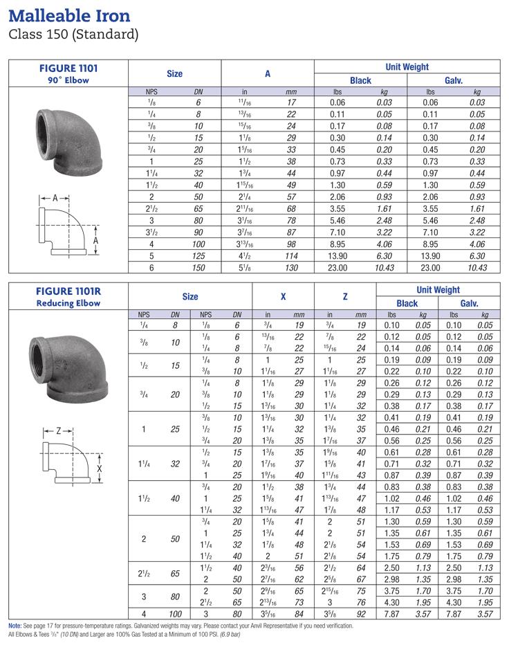
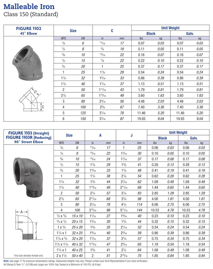
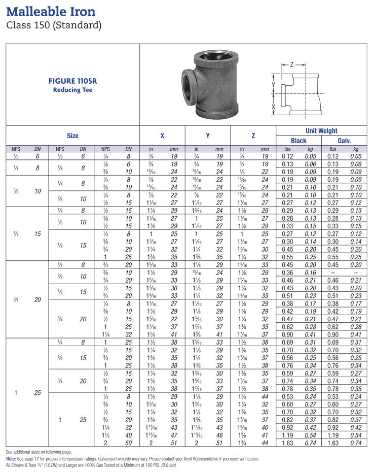
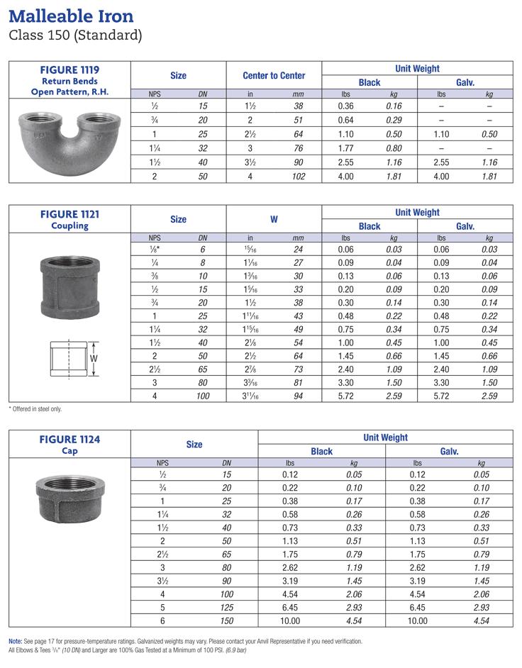
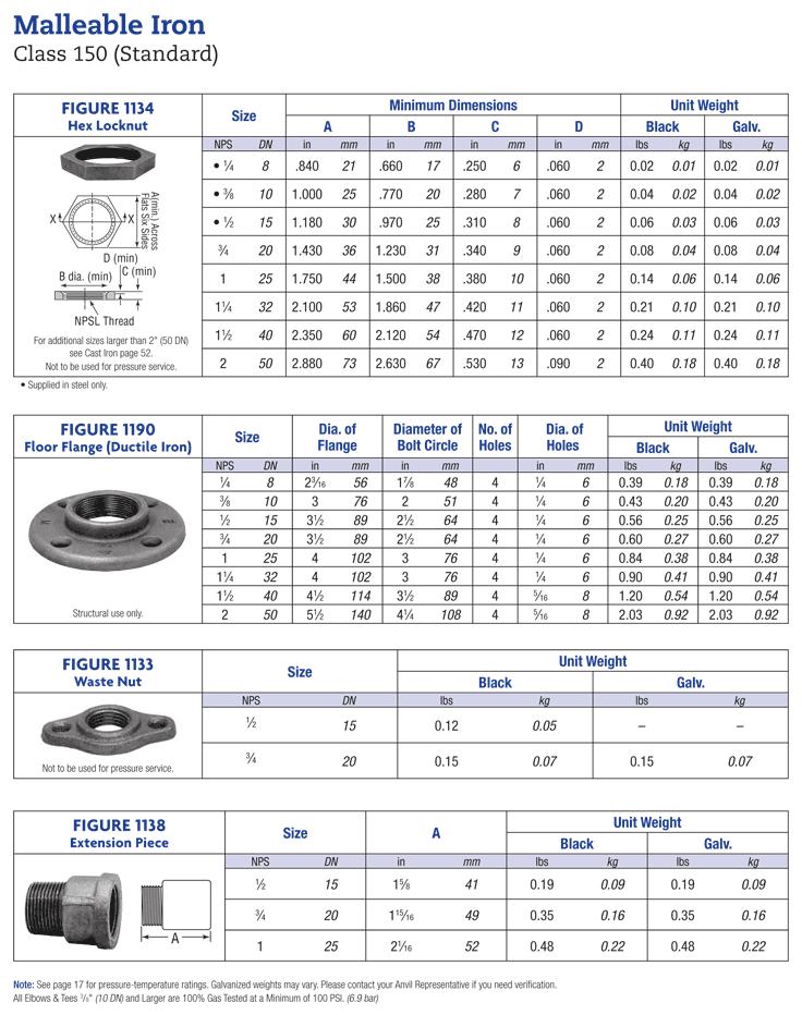
12 Malleable Iron Class 150 (standard) Coupling Right Hand Figure 1121 Size (NPS) W (in) Weight (lbs) black galv W Malleable Iron Threaded Pipe With Unions Pressure - Temperature Ratings Temp ( F) Class 150 Pressure, (psig) Class 250 Class to Note: Unions with Copper or Copper Alloy seats are not intended for use where temperature exceeds 450 F Temp ( F) Malleable Iron Threaded Fittings Pressure - Temperature Ratings Class 150 Pressure, (psig) Sizes 1 4" - 1" Class 300 Sizes 1 1 4" - 2" Sizes 2 1 2" - 3" -20 to ,000 1,500 1, ,785 1, ,575 1, ,360 1, , Anvil Class 150 (Standard Weight) Malleable Iron Fittings conform to ASME B16.3 and Unions conform to ASME B Anvil standard weight banded pattern fittings in this catalog, sizes 1 8 NPS to 6 NPS inclusive, are included in the List of Inspected Fire Protection Equipment and Materials issued by the Underwriters Laboratories, Inc. ALL ELBOWS & TEES 3 8" AND LARGER ARE 100% GAS TESTED AT A MINIMUM OF 100 PSI. (12/10/01)
13 Page 1 of 1 12/21/2013
14 Page 1 of 1 12/21/2013
 end to end (in) Weight (lbs) black galv. 1 8 1 5 16.15.15 1 4 1 13 16.46.47 3 8 1 13 16.42.43 1 2 1 15 16.44.45 3 4 2 1 16.60.")


15 Malleable Iron Unions Class 150; 250; 300 Unions Class 150 Union Figure lb. wsp 300 lb. wog non-shock UL Listed Copper or Copper Alloy to Iron Size (NPS) end to end (in) Weight (lbs) black galv x Class 250 Union, Figure lb. wsp 500lb. wog non-shock UL LIsted Class 300 union, Figure lb. wsp 600lb wog non-shock Class 300 union male and female Figure lb. wsp 600lb wog non-shock *.14* Anvil Malleable Iron Unions conform to ASME B and are in compliance with the requirements of the AAR (1994 AAR Manual of Standards and Practices). Dimensions conform to ASME B for Class 150, 250 & 300 Unions. (12/10/01)
16 Malleable Iron Unions Class 150; 250; 300 Malleable Iron Threaded Pipe With Unions Pressure - Temperature Ratings Temp ( F) Class 150 Pressure, (psig) Class 250 Class to Note: Unions with Copper or Copper Alloy seats are not intended for use where temperature exceeds 450 F Temp ( F) Malleable Iron Threaded Fittings Pressure - Temperature Ratings Class 150 Pressure, (psig) Sizes 1 4" - 1" Class 300 Sizes 1 1 4" - 2" Sizes 2 1 2" - 3" -20 to ,000 1,500 1, ,785 1, ,575 1, ,360 1, , Anvil Class 150 (Standard Weight) Malleable Iron Fittings conform to ASME B16.3 and Unions conform to ASME B Anvil standard weight banded pattern fittings in this catalog, sizes 1 8 NPS to 6 NPS inclusive, are included in the List of Inspected Fire Protection Equipment and Materials issued by the Underwriters Laboratories, Inc. ALL ELBOWS & TEES 3 8" AND LARGER ARE 100% GAS TESTED AT A MINIMUM OF 100 PSI. (12/10/01)

17 Cast Iron Threaded Fittings Class 125, (Standard) Square Head Plugs (Solid) Figure 388 Size (NPS) black Weight (lbs) galv , 1 4, 3 8 NPS plugs furnished in steel 1 / 2 and 3 4 NPS countersunk plugs furnished in malleable iron Not stocked Cast Iron Threaded Fittings Pressure - Temperature Ratings Pressure, (psig) Temp.( F) Class 125 Class to (12/10/01)
 depending on pipe size and wall")
18 Technical Services: Tel: (866) / Fax: (401) Grinnell Mechanical Products Figure 705 Flexible Coupling General Description The Figure 705 Flexible Coupling is capable of pressures up to 500 psi (34,5 bar) depending on pipe size and wall thickness. It provides a dependable method of joining pipe and is suitable for use in a variety of applications. Note Rigid Couplings are recommended for low temperature and vacuum applications. See Grinnell Figure 772 Coupling. WARNING The Figure 705 Flexible Coupling described herein must be installed and maintained in compliance with this document, in addition to the standards of any other authorities having jurisdiction. Failure to do so may impair the performance of this device. The owner is responsible for maintaining their system and devices in proper operating condition. The installing contractor or manufacturer should be contacted with any questions. Technical Data Sizes 1¼ to 12 (DN32 to DN300) Maximum Pressure See Figure 1 Approvals UL, FM, ULC, VdS, & LPCB Housing Ductile iron conforming to ASTM A-536, Grade Protective Coatings Non-lead orange paint RAL red (optional) non-lead paint Hot dipped galvanized conforming to ASTM A-153 Bolt/Nuts Track Head Bolts - conforming to ASTM A-183, Zinc Plated, (Min. Tensile = 110,000 psi/758,422 kpa) Metric - conforming to ASTM F568M Gasket (specify when ordering) Grade E EPDM, green color code -30 F (-34 C) to +230 F (+110 C) Tri-seal Grade E EPDM, green color code -30 F (-34 C) to +230 F (+110 C) Grade T Nitrile, orange color code -20 F (-29 C) to +180 F (+82 C) Grade O Fluoroelastomer, blue color code +20 F (-7 C) to +300 F (+149 C) Grade L Silicone, red gasket -30 F (-34 C) to +350 F (+177 C) (See Data Sheet G610 for aid in selecting proper gasket.) FM For Fire Protection pressure rating, listing and approval information, contact Tyco Fire & Building Products. Page of 4 OCTOBER, 2006 G110
19 Page 2 of 4 G110 B C A Pipe Size Nominal ANSI DN O.D. (mm) Max. Pressures psi (bar) Max. End Load Lbs. (kn) Max.* End Gap (mm) Deflection Nominal Dimensions Coupling Bolts Degrees per coupling / Foot (mm/m) A (mm) B (mm) C (mm) Qty. Size** (mm) Approx. Weight Lbs. (kg) 1¼ DN (42,4) 500 (34,5) 1,082.1 (4,81) 0.13 (3,3) (75,0) 2.56 (65,0) 4.19 (106,4) 1.81 (46,0) 2 3/8 x 2¼ M10 x (0,7) 1½ DN (48,3) 500 (34,5) 1,417.6 (6,30) 0.13 (3,3) (65,8) 2.75 (69,9) 4.44 (112,8) 1.81 (46,0) 2 3/8 x 2¼ M10 x (0,7) 2 DN (60,3) 500 (34,5) 2,215.1 (9,85) 0.13 (3,3) (52,5) 3.25 (82,6) 4.88 (124.0) 1.88 (47,8) 2 3/8 x 2¼ M10 x (0,8) 2½ DN (73,0) 500 (34,5) 3,245.9 (14,43) 0.13 (3,3) (43,3) 3.69 (93,7) 5.50 (139.7) 1.88 (47,8) 2 3/8 x 2¼ M10 x (0,9) DN (76,1) 500 (34,5) 3,534.3 (15,72) 0.13 (3,3) (41,7) 4.00 (101,6) 5.75 ( (47,8) 2 M12 x (1,4) 3 DN (88,9) 500 (34,5) 4,810.6 (21,39) 0.13 (3,3) (35,8) 4.38 (111,3) 6.50 (165.1) 1.88 (47,8) 2 1/2 x 3 M12 x (1,4) DN (108,0) 500 (34,5) 7,093.1 (31,55) 0.25 (6,4) (58,3) 5.50 (139,7) 7.50 (190,5) 2.06 (52,3) 2 M12 x (1,9) 4 DN (114,3) 500 (34,5) 7,952.2 (35,35) 0.25 (6,4) (55,8) 5.69 (144,5) 7.75 (196,9) 2.06 (52,3) 2 1/2 x 3 M12 x (1,8) DN (133,0) 450 (31,0) 9,741.4 (43,33) 0.25 (6,4) (46,7) 6.56 (166,6) 9.50 (241,3) 2.06 (52,3) 2 M16 x (3,3) DN (139,7) 450 (31,0) 10,691.2 (47,56) 0.25 (6,4) (45,5) 6.81 (173,0) 9.75 (247,7) 2.06 (52,3) 2 M16 x (3,3) 5 DN (141,3) 450 (31,0) 10,937.6 (48,63) 0.25 (6,4) (45,0) 6.88 (174,8) 9.75 (247,7) 2.06 (52,3) 2 5/8 x 3¼ M16 x (3,2) DN (159,0) 450 (31,0) 13,805.8 (61,41) 0.25 (6,4) (40,0) 7.56 (192,0) (261,9) 2.06 (52,3) 2 M16 x (3,4) DN (165,1) 450 (31,0) 14,932.4 (66,36) 0.25 (6,4) (38,3) 7.75 (196,9) (271,5) 2.06 (52,3) 2 M16 x (3,2) 6 DN (168,3) 450 (31,0) 15,512.2 (68,97) 0.25 (6,4) (37,5) 7.94 (201,7) (271,5) 2.06 (52,3) 2 5/8 x 3¼ M16 x (3,2) DN (216,3) 450 (31,0) 25,535.3 (113,59) 0.25 (6,4) (29,2) (255,8) (342,9) 2.31 (58,7) 2 M20 x (5,6) 8 DN (219,1) 450 (31,0) 26,291.8 (116,89) 0.25 (6,4) (29,2) (258,8) (344,4) 2.50 (63,5) 2 3/4 x 4¾ M20 x (6,6) 10 DN (273,0) 350 (24,1) 31,766.9 (141,31) 0.25 (6,4) (23,3) (322,3) (416,1) 2.63 (66,8) 2 1 x 6½ M24 x (12,7) 12 DN (323,9) 350 (24,1) 44,686.7 (198,78) 0.25 (6,4) (19,2) (379,5) (479,6) 2.63 (66,8) 2 1 x 6½ M24 x (16,6) * Maximum available gap between pipe ends. Minimum gap = 0. Maximum pressure and end load are total from all loads based on standard weight steel pipe. Pressure ratings and end loads may differ for other pipe materials and/or wall thickness. Contact Tyco Fire & Building Products for details. ** Gold color coded metric bolt sizes are available upon request. Max End Gap and Deflection is for cut grooved standard weight pipe. Values for roll grooved pipe will be 1 2 that of cut grooved. Figure 1 Nominal Dimensions figure 705 flexible coupling
20 G110 Page of 4 Limited Warranty Products manufactured by Tyco Fire & Building Products (TFBP) are warranted solely to the original Buyer for ten (10) years against defects in material and workmanship when paid for and properly installed and maintained under normal use and service. This warranty will expire ten (10) years from date of shipment by TFBP. No warranty is given for products or components manufactured by companies not affiliated by ownership with TFBP or for products and components which have been subject to misuse, improper installation or maintenance, corrosion, or other external sources of damage. Materials found by TFBP to be defective shall be either repaired or replaced, at TFBP s sole option. TFBP neither assumes, nor authorizes any person to assume for it, any other obligation in connection with the sale of products or parts of products. TFBP shall not be responsible for system design errors or inaccurate or incomplete information supplied by Buyer or Buyer s representatives. In no event shall TFBP be liable, in contract, tort, strict liability or under any other legal theory, for incidental, indirect, special or consequential damages, including but not limited to labor charges, regardless of whether TFBP was informed about the possibility of such damages, and in no event shall TFBP s liability exceed an amount equal to the sales price. The foregoing warranty is made in lieu of any and all other warranties, express or implied, including warranties of merchantability and fitness for a particular purpose. This limited warranty sets forth the exclusive remedy for claims based on failure of or defect in products, materials or components, whether the claim is made in contract, tort, strict liability or any other legal theory. This warranty will apply to the full extent permitted by law. The invalidity, in whole or part, of any portion of this warranty will not affect the remainder. Ordering Procedure When placing an order, indicate the full product name. Please specify the quantity, size, (ANSI inch size or pipe O.D.), figure number, type of gasket: Grade E EPDM Grade E EPDM Tri-Seal Grade T Nitrile Grade O Fluoroelastomer Grade L Silicone Grinnell Mechanical Products, valves, accessories and other products are available throughout the U.S., Canada, and internationally, through a network of distribution centers. You may write directly or call for the distributor nearest you. General Notes: It is the Designer s responsibility to select products suitable for the intended service and to ensure that pressure ratings and performance data are not exceeded. Always read and understand the installation instructions (IH-1000). Never remove any piping component or correct or modify any piping deficiencies without first depressurizing and draining the system. Material and gasket selection should be verified to be compatible for the specific application. Certified Company
21 Page 4 of 4 G110 TYCO FIRE & BUILDING PRODUCTS, 451 North Cannon Avenue, Lansdale Pennsylvania 19446

22 Technical Services: Tel: (866) / Fax: (401) Grinnell Mechanical Products Figure 772 Rigid Coupling - Patented General Description The Figure 772 Rigid Coupling provides a rigid joint by firmly gripping along the circumference of the pipe grooves. The Figure 772 Rigid Coupling is a proven dependable method of joining pipe and is an economical alternative to welding, threading or using flanges. It is capable of pressures up to 750 psi (51,7 bar) depending on pipe size and wall thickness. The Figure 772 Coupling is UL Listed for grounding and bonding, and is suitable for bonding systems with a maximum service entrance capacity of 200 amps. (Contact TF&BP for details) Note Rigid Couplings are recommended for low temperature and vacuum applications. WARNING The Figure 772 Rigid Coupling described herein must be installed and maintained in compliance with this document, in addition to the standards of any other authorities having jurisdiction. Failure to do so may impair the performance of this device. The owner is responsible for maintaining their system and devices in proper operating condition. The installing contractor or manufacturer should be contacted with any questions. Technical Data Sizes 1-1/4 to 24 (DN32 to DN600) Maximum Pressure See Figure 1. Approvals UL, FM, ULC, VdS, & LPCB Housing Ductile iron conforming to ASTM A-536, Grade Protective Coatings Non-lead orange paint RAL red (optional) non-lead paint Hot dipped galvanized conforming to ASTM A-153 Bolt/Nuts Track Head Bolts - conforming to ASTM A-183, Zinc Plated, (Min. Tensile = 110,000 psi/758,422 kpa) Metric - conforming to ASTM F568M Gasket (specify when ordering) Grade E EPDM, green color code -30 F (-34 C) to +230 F (+110 C) Tri-seal Grade E EPDM, green color code -30 F (-34 C) to +230 F (+110 C) Grade T Nitrile, orange color code -20 F (-29 C) to +180 F (+82 C) Grade O Fluoroelastomer, blue color code +20 F (-7 C) to +300 F (+149 C) Grade L Silicone, red gasket -30 F (-34 C) to +350 F (+177 C) (See Data Sheet G610 for aid in selecting proper gasket.) FM For Fire Protection pressure rating, listing and approval information, contact Tyco Fire & Building Products. Page of 4 JANUARY, 2008 G140
23 Page 2 of 4 G140 B C B C B C A A A 1-1/4 (DN32) - 14 (DN350) 16 (DN400) - 18 (DN450) 20 (DN500) - 24 (DN600) Nominal ANSI DN 1-1/4 DN32 1-1/2 DN40 2 DN50 2-1/2 DN65 DN65 3 DN80 4 DN100 DN125 5 DN125 DN150 6 DN150 8 DN DN DN DN DN DN DN DN600 Pipe Size O.D. (mm) (42,4) (48,3) (60,3) (73,0) (76,1) (88,9) (114,3) (139,7) (141,3) (165,1) (168,3) (219,1) (273,0) (323,9) (355,6) (406,4) (457,2) (508,0) (609,6) Max. Pressures psi (bar) 750 (51,7) 750 (51,7) 750 (51,7) 750 (51,7) 750 (51,7) 750 (51,7) 750 (51,7) 750 (51,7) 750 (51,7) 700 (48,2) 700 (48,2) 600 (41,4) 500 (34,5) 400 (27,6) 300 (20,7) 300 (20,7) 300 (20,7) 300 (20,7) 250 (17,2) Max. End Load Lbs. (kn) 1,623.2 (7,22) 2,126.5 (9,46) 3,322.6 (14,78) 4,868.9 (21,66) 5,301.4 (23,58) 7,215.8 (32,10) 11,928.2 (53,06) 17,818.7 (79,26) 18,229.3 (81,09) 23,228.2 (103,18) 24,130.1 (107,34) 35,055.8 (155,94) 45,381.3 (201,87) 51,070.5 (227,17) 46,181.4 (205,43) 60,318.6 (268,31) 76,340.7 (339,58) 94,247.8 (419,23) 113,097.3 (503,08) Max.* End Gap (mm) 0.06 (1,5) 0.08 (2,0) 0.13 (3,3) 0.13 (3,3) 0.13 (3,3) 0.13 (3,3) 0.19 (4,8) 0.19 (4,8) 0.19 (4,8) 0.19 (4,8) 0.19 (4,8) 0.19 (4,8) 0.13 (3,3) 0.13 (3,3) 0.13 (3,3) 0.13 (3,3) 0.25 (6,4) 0.25 (6,4) 0.25 (6,4) Nominal Dimensions A (mm) 2.75 (69,9) 3.00 (76,2) 3.41 (86,6) 3.91 (99,3) 4.19 (106,4) 4.63 (117,6) 5.81 (147,6) 7.02 (178,3) 7.09 (180,1) 8.09 (205,5) 8.09 (205,5) (268,2) (326,1) (391,4) (423,7) (469,9) (541,3) (596,9) (701,8) B (mm) 4.38 (111,3) 4.62 (117,3) 5.12 (130,0) 5.63 (143,0) 5.72 (145,3) 6.25 (158,8) 7.50 (190,5) 9.72 (246,9) 9.71 (246,6) (267,5) (267,5) (344,4) (416,8) (478,5) (517,6) (575,1) (638,0) (708,2) (812,8) C (mm) 1.81 (46,0) 1.81 (46,0) 1.88 (47,8) 1.88 (47,8) 2.00 (50,8) 1.88 (47,8) 1.97 (50,0) 2.06 (52,3) 2.04 (51,8) 2.13 (54,1) 2.13 (54,1) 2.62 (66,5) 2.62 (66,5) 2.62 (66,5) 2.93 (74,4) 2.93 (74,4) 3.06 (77,7) 3.06 (77,7) 3.19 (81,0) Qty Coupling Bolts Size** (mm) 3/8 x 2-1/4 M10 x 57 3/8 x 2-1/4 M10 x 57 3/8 x 2-1/4 M10 x 57 3/8 x 2-1/4 M10 x 57 - M10 x 57 3/8 x 2-1/4 M10 x 57 3/8 x 2-1/4 M10 x 57 - M16 x 83 5/8 x 3-1/4 M16 x 83 - M16 x 83 5/8 x 3-1/4 M16 x 83 3/4 x 4-3/4 M20 x x 6-1/2 M24 x x 6-1/2 M24 x 165 Approx. Weight Lbs. (kg) 1.0 (0,5) 1.0 (0,5) 1.5 (0,7) 2.5 (1,1) 2.6 (1,2) 2.6 (1,2) 3.5 (1,6) 7.5 (3,4) 7.5 (3,4) 7.6 (3,4) 7.6 (3,4) 18.0 (8,2) 24.6 (11,2) 42.0 (19,1) 2 1 x 5-1/ (21,7) 3 1 x 5-1/ (23,6) 3 1 x 5-1/ (30,8) 4 1-1/8 x 5-3/ (40,4) 4 1-1/8 x 5-3/ (43,5) * Maximum available gap between pipe ends. Minimum gap = 0. Maximum pressure and end load are total from all loads based on standard weight steel pipe. Pressure ratings and end loads may differ for other pipe materials and/or wall thickness. Contact Tyco Fire & Building Products for details. ** Gold color coded metric bolt sizes for DN32 - DN300 couplings are available upon request Max End Gap is for cut grooved standard weight pipe. Values for roll grooved pipe will be 1 2 that of cut grooved. Only available in ANSI bolt sizes. Figure 1 Nominal Dimensions figure 772 rigid coupling
24 G140 Page of 4 Limited Warranty Products manufactured by Tyco Fire & Building Products (TFBP) are warranted solely to the original Buyer for ten (10) years against defects in material and workmanship when paid for and properly installed and maintained under normal use and service. This warranty will expire ten (10) years from date of shipment by TFBP. No warranty is given for products or components manufactured by companies not affiliated by ownership with TFBP or for products and components which have been subject to misuse, improper installation or maintenance, corrosion, or other external sources of damage. Materials found by TFBP to be defective shall be either repaired or replaced, at TFBP s sole option. TFBP neither assumes, nor authorizes any person to assume for it, any other obligation in connection with the sale of products or parts of products. TFBP shall not be responsible for system design errors or inaccurate or incomplete information supplied by Buyer or Buyer s representatives. In no event shall TFBP be liable, in contract, tort, strict liability or under any other legal theory, for incidental, indirect, special or consequential damages, including but not limited to labor charges, regardless of whether TFBP was informed about the possibility of such damages, and in no event shall TFBP s liability exceed an amount equal to the sales price. The foregoing warranty is made in lieu of any and all other warranties, express or implied, including warranties of merchantability and fitness for a particular purpose. This limited warranty sets forth the exclusive remedy for claims based on failure of or defect in products, materials or components, whether the claim is made in contract, tort, strict liability or any other legal theory. This warranty will apply to the full extent permitted by law. The invalidity, in whole or part, of any portion of this warranty will not affect the remainder. Ordering Procedure When placing an order, indicate the full product name. Please specify the quantity, size, (ANSI inch size or pipe O.D.), figure number, type of gasket: Grade E EPDM Grade E EPDM Tri-Seal Grade T Nitrile Grade O Fluoroelastomer Grade L Silicone Grinnell Mechanical Products, valves, accessories and other products are available throughout the U.S., Canada, and internationally, through a network of distribution centers. You may write directly or call for the distributor nearest you. General Notes: It is the Designer s responsibility to select products suitable for the intended service and to ensure that pressure ratings and performance data are not exceeded. Always read and understand the installation instructions (IH-1000). Never remove any piping component or correct or modify any piping deficiencies without first depressurizing and draining the system. Material and gasket selection should be verified to be compatible for the specific application. Certified Company
25 Page 4 of 4 G TYCO FIRE & BUILDING PRODUCTS, 451 North Cannon Avenue, Lansdale Pennsylvania 19446
26 Technical Services: Tel: (866) / Fax: (401) Grinnell Mechanical Products Grooved Fittings, Ductile Iron & Fabricated Steel General Description Grooved fittings provide an economical and efficient method of changing direction, adding an outlet, reducing, or capping piping systems. Grooved fittings are available in ductile iron or fabricated steel as indicated. WARNING The Fittings described herein must be installed and maintained in compliance with this document, in addition to the standards of any other authorities having jurisdiction. Failure to do so may impair the performance of this device. The owner is responsible for maintaining their system and devices in proper operating condition. The installing contractor or manufacturer should be contacted with any questions. Technical Data Approvals: UL, FM, ULC, VdS, & LPCB. Maximum Working Pressure: See specific data sheet for rating of coupling being used. Material: Cast: Figures: 201, 210, 219, 221, 250, 251,and 260 -Ductile iron conforming to ASTM A-536, Grade Fabricated Steel : Figures 301, 310, 311, 312, 314, 315, 319, 320, 321, 323, 324, 325, 327, 330, 331, 341, 342, 350, 351, 360, 372, 380, 391, 392, 393, 395, 397, 398 and Carbon Steel conforming to ASTM A-53 Grade B, (Sizes 1-1/4-6 are Schedule 40); (Sizes 8-12 are Schedule 30), (Sizes are STD 0.375) Protective Coatings: Non-lead orange paint RAL red (optional) non-lead paint Hot dipped galvanized conforming to ASTM A-153 Limited Warranty Products manufactured by Tyco Fire & Building Products (TFBP) are warranted solely to the original Buyer for ten (10) years against defects in material and workmanship when paid for and properly installed and maintained under normal use and service. This warranty will expire ten (10) years from date of shipment by TFBP. No warranty is given for products or components manufactured by companies not affiliated by ownership with TFBP or for products and components which have been subject to misuse, improper installation or maintenance, corrosion, or other external sources of damage. Materials found by TFBP to be defective shall be either repaired or replaced, at TFBP s sole option. TFBP neither assumes, nor authorizes any person to assume for it, any other obligation in connection with the sale of products or parts of products. TFBP shall not be responsible for system design errors or inaccurate or incomplete information supplied by Buyer or Buyer s representatives. In no event shall TFBP be liable, in contract, tort, strict liability or under any other legal theory, for incidental, indirect, special or consequential damages, including but not limited to labor charges, regardless of whether TFBP was informed about the possibility of such damages, and in no event shall TFBP s liability exceed an amount equal to the sales price. The foregoing warranty is made in lieu of any and all other warranties, express or implied, including warranties of merchantability and fitness for a particular purpose. FM For Fire Protection pressure rating, listing and approval information, contact Tyco Fire & Building Products. This limited warranty sets forth the exclusive remedy for claims based on failure of or defect in products, materials or components, whether the claim is made in contract, tort, strict liability or any other legal theory. This warranty will apply to the full extent permitted by law. The invalidity, in whole or part, of any portion of this warranty will not affect the remainder. Ordering Procedure When placing an order, indicate the full product name. Please specify the quantity, figure number, wall thickness, and size. Grinnell Mechanical Products, valves, accessories and other products are available throughout the U.S., Canada, and internationally, through a network of distribution centers. You may write directly or call for the distributor nearest you. Page of 24 JANUARY, 2008 G180
27 Page 2 of 24 G180 Figure 1 Nominal Dimensions Figures 201 & 210 C to E FIGURE 210 CAST 90 ELBOW FIGURE 201 CAST 45 ELBOW C to E Friction Resistance (Expressed as Equivalent Straight Pipe) Nominal Pipe Size Elbows 90 Feet (m) Elbows 45 Feet (m) ANSI DN O.D. (mm) 1-1/4 DN (42,4) 1.9 (0,6) 1.0 (0,3) 1-1/2 DN (48,3) 2.3 (0,7) 1.2 (0,4) 2 DN (60,3) 3.2 (1,0) 1.6 (0,5) 2-1/2 DN (73,0) 3.9 (1,2) 2.0 (0,6) DN (76,1) 4.1 (1,2) 2.1 (0,6) 3 DN (88,9) 4.9 (1,5) 2.4 (0,7) DN (108,0) 6.5 (2,0) 3.3 (1,0) 4 DN (114,3) 6.5 (2,0) 3.3 (1,0) DN (133,0) 8.0 (2,4) 4.0 (1,2) DN (139,7) 8.0 (2,4) 4.1 (1,3) 5 DN (141,3) 8.2 (2,5) 4.1 (1,3) DN (159,0) 9.5 (2,9) 4.8 (1,4) DN (165,1) 9.5 (2,9) 4.8 (1,4) 6 DN (168,3) 9.9 (3,0) 5.0 (1,5) DN (216,3) 13.1 (4,0) 6.6 (2,0) 8 DN (219,1) 13.1 (4,0) 6.6 (2,0) 10 DN (273,0) 16.5 (5,0) 8.3 (2,5) 12 DN (323,9) 19.9 (6,1) 9.9 (3,0) 14 DN (355,6) 23.0 (7,0) 18.0 (5,5) 16 DN (406,4) 25.9 (7,9) 20.0 (6,1) 18 DN (457,2) 28.9 (8,8) 23.0 (7,0) 20 DN (508,0) 33.1 (10,1) 25.9 (7,9) 24 DN (609,6) 40.0 (12,2) 29.9 (9,1) Nominal Pipe Size Figure 201 Figure 210 ANSI DN O.D. (mm) Nominal C to E (mm) Approx. Weight Lbs. (kg) Nominal C to E (mm) Approx. Weight Lbs. (kg) 1-1/4 DN (42,4) 1.75 (44,5) 0.9 (0,4) 2.75 (69,9) 1.0 (0,5) 1-1/2 DN (48,3) 1.75 (44,5) 1.1 (0,5) 2.75 (69,9) 1.2 (0,6) 2 DN (60,3) 2.00 (50,8) 1.8 (0,8) 3.25 (82,6) 2.0 (0,9) 2-1/2 DN (73,0) 2.25 (57,2) 2.2 (1,0) 3.75 (95,3) 3.0 (1,4) DN (76,1) 2.25 (57,2) 2.2 (1,0) 3.75 (95,3) 3.0 (1,4) 3 DN (88,9) 2.50 (63,5) 3.5 (1,6) 4.25 (108,0) 4.5 (2,0) DN (108,0) 2.88 (73,0) 5.5 (2,5) 4.75 (120,7) 8.5 (3,9) 4 DN (114,3) 3.00 (76,2) 5.2 (2,4) 5.00 (127,0) 8.5 (3,9) DN (133,0) 3.25 (82,6) 7.7 (3,5) 5.25 (133,4) 11.3 (5,1) DN (139,7) 3.25 (82,6) 7.7 (3,5) 5.50 (139,7) 11.3 (5,1) 5 DN (141,3) 3.25 (82,6) 8.5 (3,9) 5.50 (139,7) 13.5 (6,1) DN (159,0) 3.50 (88,9) 12.0 (5,4) 6.00 (152,4) 14.6 (6,6) DN (165,1) 3.50 (88,9) 12.0 (5,4) 6.50 (165,1) 18.5 (8,4) 6 DN (168,3) 3.50 (88,9) 12.0 (5,4) 6.50 (165,1) 18.5 (8,4) DN (216,3) 4.25 (108,0) 23.0 (10,4) 7.75 (196,9) 36.5 (16,6) 8 DN (219,1) 4.25 (108,0) 23.0 (10,4) 7.75 (196,9) 36.5 (16,6) 10 DN (273,0) 4.75 (120,7) 31.0 (14,1) 9.00 (228,6) 60.0 (27,2) 12 DN (323,9) 5.25 (133,4) 40.0 (18,1) (254,0) 67.0 (30,4)
28 G180 Page of 24 Friction Resistance (Expressed as Equivalent Straight Pipe) Nominal Pipe Size ANSI DN 1-1/4 DN32 1-1/2 DN40 2 DN50 2-1/2 DN65 DN65 3 DN80 DN100 4 DN100 DN125 DN125 5 DN125 DN150 DN150 6 DN150 DN200 8 DN DN DN DN DN DN DN DN600 O.D. (mm) (42,4) (48,3) (60,3) (73,0) (76,1) (88,9) (108,0) (114,3) (133,0) (139,7) (141,3) (159,0) (165,1) (168,3) (216,3) (219,1) (273,0) (323,9) (355,6) (406,4) (457,2) (508,0) (609,6) Tee Branch Feet (m) 4.8 (1,5) 5.8 (1,8) 8.0 (2,5) 9.8 (3,0) 10.3 (3,1) 12.2 (3,7) 16.3 (5,0) 16.3 (5,0) 20.0 (6,1) 20.0 (6,1) 20.5 (6,3) 23.8 (7,2) 23.8 (7,2) 24.8 (7,6) 32.8 (10,0) 32.8 (10,0) 41.3 (12,6) 49.7 (15,1) 67.9 (20,7) 78.1 (23,8) 85.0 (25,9) (30,5) (35,1) Tee Run Feet (m) 1.9 (0,6) 2.3 (0,7) 3.2 (1,0) 3.9 (1,2) 4.1 (1,2) 4.9 (1,5) 6.5 (2,0) 6.5 (2,0) 8.0 (2,4) 8.0 (2,4) 8.2 (2,5) 9.5 (2,9) 9.5 (2,9) 9.9 (3,0) 13.1 (4,0) 13.1 (4,0) 16.5 (5,0) 19.9 (6,1) 23.0 (7,0) 25.9 (7,9) 28.9 (8,8) 33.1 (10,1) 40.0 (12,2) For the reducing tee branches, use the value that is corresponding to the branch size. Example: For 8 x 8 x 2 tee, the branch value of 2 is 8.0 feet. For sizes not listed interpolate from the values shown. C to E FIGURE 219 CAST TEE C to E E to E FIGURE 260 CAST END CAP Nominal Pipe Size Figure 219 Figure 260 ANSI DN 1 DN25 1-1/4 DN32 1-1/2 DN40 2 DN50 2-1/2 DN65 DN65 3 DN80 DN100 4 DN100 DN125 DN125 5 DN125 DN150 DN150 6 DN150 DN200 8 DN DN DN300 O.D. (mm) (33,4) (42,4) (48,3) (60,3) (73,0) (76,1) (88,9) (108,0) (114,3) (133,0) (139,7) (141,3) (159,0) (165,1) (168,3) (216,3) (219,1) (273,0) (323,9) Nominal C to E (mm) Approx. Weight Lbs. (kg) 2.75 (69,9) 2.75 (69,9) 3.25 (82,6) 3.75 (95,3) 3.75 (95,3) 4.25 (108,0) 4.75 (120,7) 5.00 (127,0) 5.25 (133,4) 5.50 (139,7) 5.50 (139,7) 6.00 (152,4) 6.50 (165,1) 6.50 (165,1) 7.75 (196,9) 7.75 (196,9) 9.00 (228,6) (254,0) 1.4 (0,6) 1.8 (0,8) 2.7 (1,2) 5.8 (2,6) 5.8 (2,6) 7.0 (3,2) 11.5 (5,2) 11.8 (5,4) 10.6 (4,8) 15.2 (6,9) 17.0 (7,7) 13.9 (6,3) 26.0 (11,8) 26.0 (11,8) 45.0 (20,4) 45.0 (20,4) 72.1 (32,7) 92.5 (42,0) Nominal E to E (mm) 0.88 (22,4) 0.88 (22,4) 0.88 (22,4) 0.88 (22,4) 0.88 (22,4) 0.94 (23,9) 0.88 (22,4) Figure 2 Nominal Dimensions Figures 219 & 260 Approx. Weight Lbs. (kg) 0.3 (0,1) 0.4 (0,2) 0.6 (0,3) 0.9 (0,4) 0.9 (0,4) 1.1 (0,5) 1.1 (0,5) 1.00 (25,4) 2.6 (1,2) 0.92 (23,4) 1.00 (25,4) 4.7 (2,1) 5.0 (2,3) 1.00 (25,4) 1.00 (25,4) 7.5 (3,4) 7.5 (3,4) 1.19 (30,2) 1.25 (31,8) 1.25 (31,8) - Available with tapped plugs. Contact Tyco Fire & Building Products (5,8) 20.0 (9,1) 36.0 (16,3)
29 Page 4 of 24 G180 Nominal Pipe Size Figure 250 Figure 350 ANSI DN 1-1/2 x 1-1/4 DN40 x DN32 2 x 1-1/4 DN50 x DN32 2 x 1-1/2 DN50 x DN40 2-1/2 x 1-1/4 DN65 x DN32 2-1/2 x 1-1/2 DN65 x DN40 2-1/2 x 2 DN65 x DN50 3 x 1-1/4 DN80 x DN32 3 x 1-1/2 DN80 x DN40 3 x 2 DN80 x DN50 3 x 2-1/2 DN80 x DN65 4 x 1-1/4 DN100 x DN32 4 x 1-1/2 DN100 x DN40 4 x 2 DN100 x DN50 4 x 2-1/2 DN100 x DN65 4 x 3 DN100 x DN80 5 x 1-1/2 DN125 x DN40 5 x 2 DN125 x DN50 5 x 2-1/2 DN125 x DN65 5 x 3 DN125 x DN80 5 x 4 DN125 x DN100 6 x 2 DN150 x DN50 6 x 2-1/2 DN150 x DN65 6 x 3 DN150 x DN80 6 x 4 DN150 x DN100 6 x 5 DN15 0 x DN125 O.D. (mm) x (48,3 x 42,4) x (60,3 x 42,4) x (60,3 x 48,3) x (73,0 x 42,4) x (73,0 x 48,3) x (73,0 x 60,3) x (88,9 x 42,4) x (88,9 x 48,3) x (88,9 x 60,3) x (88,9 x 70,3) x (114,3 x 42,4) x (114,3 x 48,3) x (114,3 x 60,3) x (114,3 x 73,2) x (114,3 x 88,9) x (141,3 x 48,3) x (141,3 x 60,3) x (141,3 x 73,0) x (141,3 x 88,9) x (141,3 x 114,3) x (168,3 x 60,3) x (168,3 x 73,0) x (168,3 x 88,9) x (168,3 x 114,3) x (168,3 x 141,3) Nominal E to E (mm) Approx. Weight Lbs. (kg) 2.50 (63,5) 2.50 (63,5) 2.50 (63,5) 1.0 (0,5) 1.3 (0,6) 1.2 (0,5) 2.50 (63,5) 2.50 (63,5) 2.50 (63,5) 1.3 (0,6) 1.3 (0,6) 1.5 (0,7) 3.00 (76,2) 3.00 (76,2) 3.00 (76,2) 2.3 (1,0) 2.3 (1,0) 3.0 (1,4) 3.50 (88,9) 3.50 (88,9) 4.00 (101,6) 4.00 (101,6) 4.00 (101,6) 4.00 (101,6) 4.00 (101,6) 4.4 (2,0) 4.5 (2,0) 6.0 (2,7) 6.0 (2,7) 6.0 (2,7) 5.9 (2,6) 5.8 (2,6) Nominal E to E (mm) 2.50 (63,5) 2.50 (63,5) 2.50 (63,5) Approx. Weight Lbs. (kg) 0.6 (0,3) 0.8 (0,4) 0.8 (0,4) 2.50 (63,5) 1.3 (0,6) 3.00 (76,2) 3.00 (76,2) 2.2 (1,0) 2.3 (1,0) 3.50 (88,9) 3.50 (88,9) 3.50 (88,9) 4.6 (2,1) 4.6 (2,1) 4.5 (2,0) E to E FIGURE 250 CAST CONCENTRIC REDUCER SIZES 1-1/2-6 E to E FIGURE 350 FABRICATED CONCENTRIC REDUCER SIZES 1-1/2-6 Figure 3 (1 of 2) Nominal Dimensions Figure 250 & Figure 350
30 G180 Page of 24 Nominal Pipe Size Figure 250 Figure 350 ANSI DN 8 x 2 DN200 x DN50 8 x 2-1/2 DN200 x DN65 8 x 3 DN200 x DN80 8 x 4 DN200 x DN100 8 x 5 DN200 x DN125 8 x 6 DN200 x DN x 4 DN250 x DN x 5 DN250 x DN x 6 DN250 x DN x 8 DN250 x DN x 4 DN300 x DN x 6 DN300 x DN x 8 DN300 x DN x 10 DN300 x DN x 6 DN350 x DN x 8 DN350 x DN x 10 DN350 x DN x 12 DN350 x DN x 8 DN400 x DN x 10 DN400 x DN x 12 DN400 x DN x 14 DN400 x DN x 12 DN450 x DN x 14 DN450 x DN x 16 DN450 x DN x 10 DN500 x DN x 12 DN500 x DN x 14 DN500 x DN x 16 DN500 x DN x 18 DN500 x DN x 10 DN600 x DN x 12 DN600 x DN x 14 DN600 x DN x 16 DN600 x DN x 18 DN600 x DN x 20 DN600 x DN500 O.D. (mm) x (219,1 x 60,3) x (219,1 x 73,0) x (219,1 x 88,9) x (219,1 x 114,3) x (219,1 x 141,3) x (219,1 x 168,3) x (273,0 x 114,3) x (273,0 x 141,3) x (273,0 x 168,3) x (273,0 x 219,1) x (323,9 x 114,3) x (323,9 x 168,3) x (323,9 x 219,1) x (323,9 x 273,0) x (355,6 x 168,3) x (355,6 x 219,1) x (355,6 x 273,0) x (355,6 x 323,9) x (406,4 x 219,1) x (406,4 x 273,0) x (406,4 x 323,9) x (406,4 x 355,6) x (457,2 x 323,9) x (457,2 x 355,6) x (457,2 x 406,4) x (508,0 x 273,0) x (508,0 x 323,9) x (508,0 x 355,6) x (508,0 x 406,4) x (508,0 x 457,2) x (609,6 x 273,0) x (609,6 x 323,9) x (609,6 x 355,6) x (609,6 x 406,4) x (609,6 x 457,2) x (609,6 x 508,0) Nominal E to E (mm) Approx. Weight Lbs. (kg) 5.00 (127,0) 5.00 (127,0) 5.00 (127,0) 5.00 (127,0) 12.0 (5,5) 11.9 (5,4) 11.3 (5,1) 10.8 (4,9) Nominal E to E (mm) 5.00 (127,0) 5.00 (127,0) Approx. Weight Lbs. (kg) 12.2 (5,5) 12.1 (5,5) 6.00 (152,4) 6.00 (152,4) 6.00 (152,4) 6.00 (152,4) 7.00 (177,8) 7.00 (177,8) 7.00 (177,8) 7.00 (177,8) (330,2) (330,2) (330,2) (330,2) (355,6) (355,6) (355,6) (355,6) (381,0) (381,0) (381,0) (508,0) (508,0) (508,0) (508,0) (508,0) (508,0) (508,0) (508,0) (508,0) (508,0) (508,0) 21.9 (10,0) 21.6 (9,8) 21.1 (9,6) 19.5 (8,9) 28.0 (12,7 ) 30.0 (13,6 ) 28.0 (12,7 ) 33.0 (15,0 ) 58.0 (26,4 ) 58.5 (26,5) 59.3 (27,0) 60.0 (27,3) 68.5 (31,1) 69.5 (31,1) 70.0 (31,8) 71.0 (32,3) 83.0 (37,7) 84.0 (38,2) 85.0 (38,6) (52,3) (54,5) (55,5) (56,4) (56,8) (66,8) (62,7) (63,6) (65,9) (67,3) (68,2) E to E FIGURE 250 CAST CONCENTRIC REDUCER SIZES 8-24 E to E FIGURE 350 FABRICATED CONCENTRIC REDUCER SIZES 8-24 Figure 3 (2 of 2) Nominal Dimensions Figure 250 & Figure 350
31 Page of 24 G180 C to E C to E FIGURE 301 FABRICATED 45 ELBOW (FULL FLOW) FIGURE 310 FABRICATED 90 ELBOW (FULL FLOW) FIGURE 312 FABRICATED 22-1/2 ELBOW (SEGMENT WELDED) FIGURE 311 FABRICATED 11-1/4 ELBOW (SEGMENT WELDED) Nominal Pipe Size Figure 301 Figure 310 Figure 312 Figure 311 ANSI DN 1-1/4 DN32 1-1/2 DN40 2 DN50 2-1/2 DN65 3 DN80 4 DN100 5 DN125 6 DN150 8 DN DN DN DN DN DN DN DN600 O.D. (mm) (42,4) (48,3) (60,3) (73,0) (88,9) (114,3) (141,3) (168,3) (219,1) (273,0) (323,9) (355,6) (406,4) (457,2) (508,0) (609,6) Nominal C to E (mm) 2.50 (63,5) 2.50 (63,5) 2.75 (69,9) 3.00 (76,2) 3.38 (85,9) 4.00 (101,6) 5.00 (127,0) 5.50 (139,7) 7.25 (184,2) 8.50 (215,9) (254,0) 8.75 (228,3) (254,0) (285,8) (317,5) (381,0) Approx. Weight Lbs. (kg) 1.1 (0,5) 1.3 (0,6) 1.8 (0,8) 2.9 (1,3) 4.6 (2,1) 7.5 (3,4) 12.5 (5,7) 12.0 (5,4) 34.0 (15,4) 56.0 (25,4) 98.0 (44,5) (47,6) (52,2) (65,8) (81,6) (133,4) Nominal C to E (mm) 3.88 (98,6) 4.25 (108,0) 4.38 (111,3) 5.75 (146,1) 5.88 (149,4) 7.50 (190,5) 9.50 (241,3) (273,1) (381,0) (457,2) (533,4) (533,4) (609,6) (685,8) (838,2) (914,4) Approx. Weight Lbs. (kg) 1.4 (0,6) 1.8 (0,8) 2.5 (1,1) 5.0 (2,3) 6.5 (2,9) 11.7 (5,3) 21.0 (9,5) 30.0 (13,6) 60.0 (27,2) (45,4) (63,5) (81,6) (99,8) (127,0) (158,8) (217,7) Nominal C to E (mm) 1.75 (44,5) 1.75 (44,5) 1.88 (47,8) 2.00 (50,8) 2.25 (57,2) 2.63 (66,8) 2.88 (73,2) 3.13 (79,5) 3.88 (98,6) 4.38 (111,3) 4.88 (124,0) 5.00 (127,0) 5.00 (127,0) 5.50 (139,7) 6.00 (152,4) 7.00 (177.8) Approx. Weight Lbs. (kg) 0.4 (0,2) 0.5 (0,2) 0.6 (0,3) 0.7 (0.3) 1.4 (0,6) 2.4 (1,1) 4.1 (1,9) 5.6 (2,5) 11.1 (5,0) 14.0 (6,4) 22.0 (10,0) 46.0 (20,9) 52.2 (23,7) 65.0 (29,5) 80.0 (36,3) (50,8) Nominal C to E (mm) 1.38 (35,1) 1.38 (35,1) 1.38 (35,1) 1.50 (38,1) 1.50 (38,1) 1.75 (44,5) 2.00 (50,8) 2.00 (50.8) 2.00 (50,8) 2.13 (54,1) 2.25 (57,2) 3.50 (88,9) 4.00 (101,6) 4.50 (114,3) 5.00 (127,0) 6.00 (152,4) Approx. Weight Lbs. (kg) 0.4 (0,2) 0.5 (0,2) 0.6 (0,3) 1.1 (0,5) 1.2 (0,5) 2.2 (1,0) 3.3 (1,5) 4.6 (2,1) 8.7 (3,9) 9.1 (4,1) 16.7 (7,6) 32.1 (14,6) 42.0 (19,1) 53.2 (24,2) 65.7 (29,8) 96.0 (43,5) Figure 4 Nominal Dimensions Figures 301, 310, 312 & 311
32 G180 Page of 24 C to E E to E C to E FIGURE 319 FABRICATED TEE (SEGMENT WELDED) FIGURE 360 FABRICATED END CAP Nominal Pipe Size Figure 319 Figure 360* ANSI DN 14 DN DN DN DN DN600 O.D. (mm) (355,6) (406,4) (457,2) (508,0) (609,6) Nominal C to E (mm) 11.0 (279,0) (305,0) (394,0) (438,0) (508,0) Approx. Weight Lbs. (kg) 48.0 (53,5) (66,2) (98,9) (125,0) (172,0) Nominal C to E (mm) 8.50 (215,9) 9.00 (228,6) (254,0) 11,00 (279,4) (317,5) * Available with tapped plugs. Contact Tyco Fire & Building Products. Figure 5 Nominal Dimensions Figures 319 & 360 Approx. Weight Lbs. (kg) 45.0 (20,4) 50.3 (22,8) 66.0 (29,9) 88.0 (39,9) (54,0)
33 Page 8 of 24 G180 ANSI DN 1-1/2 x 1-1/2 x 1-1/4 DN40 x DN40 x DN32 2 x 2 x 1-1/2 DN50 x DN50 x DN40 2-1/2 x 2-1/2 x 1-1/4 DN65 x DN65 x DN32 2-1/2 x 2-1/2 x 1-1/2 DN65 x DN65 x DN40 2-1/2 x 2-1/2 x 2 DN65 x DN65 x DN50 3 x 3 x 1 DN80 x DN80 x DN25 3 x 3 x 1-1/2 DN80 x DN80 x DN40 3 x 3 x 2 DN80 x DN80 x DN50 3 x 3 x 2-1/2 DN80 x DN80 x DN65 4 x 4 x 1-1/4 DN100 x DN100 x DN32 4 x 4 x 1-1/2 DN100 x DN100 x DN40 4 x 4 x 2 DN100 x DN100 x DN50 4 x 4 x 2-1/2 DN100 x DN100 x DN65 4 x 4 x 3 DN100 x DN100 x DN80 5 x 5 x 2 DN125 x DN125 x DN50 5 x 5 x 2-1/2 DN125 x DN125 x DN65 5 x 5 x 3 DN125 x DN125 x DN80 5 x 5 x 4 DN125 x DN125 x DN100 6 x 6 x 2 DN150 x DN150 x DN50 6 x 6 x 2-1/2 DN150 x DN150 x DN65 6 x 6 x 3 DN150 x DN150 x DN80 6 x 6 x 4 DN150 x DN150 x DN100 6 x 6 x 5 DN150 x DN150 x DN125 8 x 8 x 2 DN200 x DN200 x DN50 8 x 8 x 3 DN200 x DN200 x DN80 8 x 8 x 4 DN200 x DN200 x DN100 8 x 8 x 5 DN200 x DN200 x DN125 8 x 8 x 6 DN200 x DN200 x DN x 10 x 2 DN250 x DN250 x DN50 10 x 10 x 3 DN250 x DN250 x DN80 10 x 10 x 4 DN250 x DN250 x DN x 10 x 5 DN250 x DN250 x DN x 10 x 6 DN250 x DN250 x DN x 10 x 8 DN250 x DN250 x DN200 Nominal Pipe Size Figure 321 Figure 221 O.D. (mm) x x (48,3 x 48,3 x 42,4) x x (60,3 x 60,3 x 48,3) x x (73,0 x 73,0 x 42,4) x x (73,0 x 73,0 x 48,3) x x (73,0 x 73,0 x 60,3) x x (88,9 x 88,9 x 33,4) x x (88,9 x 88,9 x 48,3) x x (88,9 x 88,9 x 60,3) x x (88,9 x 88,9 x 73,0) x x (114,3 x 114,3 x 42,4) x x (114,3 x 114,3 x 48,3) x x (114,3 x 114,3 x 60,3) x x (114,3 x 114,3 x 73,0) x x (114,3 x 114,3 x 88,9) x x (141,3 x 141,3 x 60,3) x x (141,3 x 141,3 x 73,0) x x (141,3 x 141,3 x 88,9) x x (141,3 x 141,3 x 114,3) x x (168,3 x 168,3 x 60,3) x x (168,3 x 168,3 x 73,0) x x (168,3 x 168,3 x 88,9) x x (168,3 x 168,3 x 114,3) x x (168,3 x 168,3 x 141,3) x x (219,1 x 219,1 x 60,3) x x (219,1 x 219,1 x 88,9) x x (219,1 x 219,1 x 114,1) x x (219,1 x 219,1 x 141,3) x x (219,1 x 219,1 x 168,3) x x (273,0 x 273,0 x 60,3) x x (273,0 x 273,0 x 88,9) x x (273,0 x 273,0 x 114,3) x x (273,0 x 273,0 x 141,3) x x (273,0 x 273,0 x 168,3) x x (273,0 x 273,0 x 219,1) Nominal C to E (mm) 2.75 (69,9) Approx. Weight Lbs. (kg) 1.5 (0,7) 3.75 (95,3) 3.75 (95,3) 3.75 (95,3) 4.2 (1,9) 4.2 (1,9) 4.2 (1,9) 4.25 (108,0) 5.3 (2,4) 4.25 (108,0) 5.00 (127,0) 5.00 (127,0) 5.8 (2,6) 9.8 (4,4) 9.9 (4,5) 5.00 (127,0) 10.3 (4,7) 5.50 (139,7) 5.50 (139,7) 5.50 (139,7) 5.50 (139,7) 14.5 (6,6) 14.8 (6,7) 15.2 (6,9) 15.8 (7,2) 6.50 (165,1) 26.5 (12,0) 6.50 (165,1) 7.75 (196,9) 7.75 (196,9) 7.75 (196,9) 7.75 (196,9) 7.75 (196,9) 9.00 (228,6) 9.00 (228,6) 9.00 (228,6) 9.00 (228,6) 9.00 (228,6) 9.00 (228,6) , (16,4) 36.5 (16,6) 36.6 (16,6) 36.8 (16,7) 37.0 (16,8) 57.1 (25,9) 57.4 (26,0) 57.6 (26,1) 57.8 (26,2) 58.0 (26,3) 58.4 (26,5) Nominal C to E (mm) Approx. Weight Lbs. (kg) 3.25 (82,6) 2.7 (1,2) 4.25 (108,0) 5.0 (2,3) 4.25 (108,0) 5.5 (2,5) 5.00 (127,0) 9.40 (4,3) 5.00 (127,0) 10.3 (4,7) 6.50 (165,1) 16.4 (7,4) 6.50 (165,1) 6.50 (165,1) 17.0 (7,7) 17.5 (7,9) C to E C to E FIGURE 321 FABRICATED REDUCING TEE (SEGMENT WELDED) C to E FIGURE 221 CAST REDUCING TEE C to E Figure 6 (1 of 2) Nominal Dimensions Figures 321 & Figures 221
34 G180 Page of 24 ANSI DN 12 x 12 x 3 DN300 x DN300 x DN80 12 x 12 x 4 DN300 x DN300 x DN x 12 x 5 DN300 x DN300 x DN x 12 x 6 DN300 x DN300 x DN x 12 x 8 DN300 x DN300 x DN x 12 x 10 DN300 x DN300 x DN x 14 x 6 DN350 x DN350 x DN x 14 x 8 DN350 x DN350 x DN x 14 x 10 DN350 x DN350 x DN x 14 x 12 DN350 x DN350 x DN x 16 x 4 DN400 x DN400 x DN x 16 x 8 DN400 x DN400 x DN x 16 x 10 DN400 x DN400 x DN x 16 x 12 DN400 x DN400 x DN x 16 x 14 DN400 x DN400 x DN x 18 x 8 DN450 x DN450 x DN x 18 x 10 DN450 x DN450 x DN x 18 x 12 DN450 x DN450 x DN x 18 x 14 DN450 x DN450 x DN x 18 x 16 DN450 x DN450 x DN x 20 x 14 DN500 x DN500 x DN x 20 x 16 DN500 x DN500 x DN x 20 x 18 DN500 x DN500 x DN x 24 x 10 DN600 x DN600 x DN x 24 x 12 DN600 x DN600 x DN x 24 x 14 DN600 x DN600 x DN x 24 x 16 DN600 x DN600 x DN x 24 x 18 DN600 x DN600 x DN x 24 x 20 DN600 x DN600 x DN500 Nominal Pipe Size Figure 321 Figure 221 O.D. (mm) x x (323,9 x 323,9 x 88,9) x x (323,9 x 323,9 x 141,3) x x (323,9 x 323,9 x 114,3) x x (323,9 x 323,9 x 219,1) x x (323,9 x 323,9 x 219,1) x x (323,9 x 323,9 x 273,0) x x (355,6 x 355,6 x 168,3) x x (355,6 x 355,6 x 219,1) x x (355,6 x 355,6 x 273,0) x x (355,6 x 355,6 x 323,9) x x (406,4 x 406,4 x 114,3) x x (406,4 x 406,4 x 219,1) x x (406,4 x 406,4 x 273,0) x x (406,4 x 406,4 x 323,9) x x (406,4 x 406,4 x 355,6) x x (457,2 x 457,2 x 219,1) x x (457,2 x 457,2 x 273,0) x x (457,2 x 457,2 x 323,9) x x (457,2 x 457,2 x 355,6) x x (457,2 x 457,2 x 406,4) x x (508,0 x 508,0 x 355,6) x x (508,0 x 508,0 x 406,4) x x (508,0 x 508,0 x 457,2) x x (609,6 x 609,6 x 273,0) x x (609,6 x 609,6 x 323,9) x x (609,6 x 609,6 x 355,6) x x (609,6 x 609,6 x 457,2) x x (609,6 x 609,6 x 406,4) x x (609,6 x 609,6 x 508,0) Nominal C to GE (mm) (254,0) (254,0) (254,0) (254,0) (254,0) (254,0) (279,4) (279,4) (279,4) (279,4) (304,8) (304,8) (304,8) (304,8) (304,8) (393,7) (393,7) (393,7) (393,7) (393,7) (450,9) (450,9) (450,9) (508,0) (508,0) (508,0) (508,0) (508,0) (508,0) Approx. Weight Lbs. (kg) 80.2 (36,4) 80.5 (36,5) 80.7 (36,6) 80.9 (36,7) 91.4 (41,5) 91.8 (41,6) (49,0) (49,9) (51,3) (52,2) (59,9) (63,5) (64,9) (66,7) (68,0) (87,5) (89,4) (90,7) (92,5) (95,3) (155,7) (117,9) (124,7) (156,5) (157,4) (158,8) (161,0) (163,3) (167,8) Nominal C to GE (mm) Approx. Weight Lbs. (kg) C to E C to E FIGURE 321 FABRICATED REDUCING TEE (SEGMENT WELDED) C to E FIGURE 221 CAST REDUCING TEE C to E Figure 6 (2 of 2) Nominal Dimensions Figures 321 & Figures 221
35 Page 10 of 24 G180 ANSI DN Nominal Pipe Size O.D. (mm) Nominal C to LE (mm) Nominal C to SE (mm) Approx. Weight Lbs. (kg) C to LE 3 x 3 x 2 DN80 x DN80 x DN50 3 x 3 x 2-1/2 DN80 x DN80 x DN x x (88,9 x 88,9 x 60,3) x x (88,9 x 88,9 x 73,0) 8.50 (215,9) 8.50 (215,9) 3.25 (82,6) 3.25 (82,6) 9.9 (4,5) 11.5 (5,2) C to SE C to LE 4 x 4 x 2 DN100 x DN100 x DN50 4 x 4 x 2-1/2 DN100 x DN100 x DN65 4 x 4 x 3 DN100 x DN100 x DN x x (114,3 x 114,3 x 60,3) x x (114,3 x 114,3 x 73,0) x x (114,3 x 114,3 x 88,9) (266,7) (266,7) (266,7) 3.75 (95,3) 3.75 (95,3) 3.75 (95,3) 16.0 (7,3) 17.0 (7,7) 18.6 (8,4) FIGURE 325 FABRICATED 45 REDUCING LATERAL (SEGMENT WELDED) 5 x 5 x 2 DN125 x DN125 x DN x x (141,3 x 141,3 x 60,3) (317,5) 4.00 (101,6) 23.0 (10,4) 5 x 5 x 2-1/2 DN125 x DN125 x DN x x (141,3 x 141,3 x 73,0) (317,5) 4.00 (101,6) 23.5 (10,7) 5 x 5 x 3 DN125 x DN125 x DN x x (141,3 x 141,3 x 88,9) (317,5) 4.00 (101,6) 27.0 (12,2) 5 x 5 x 4 DN125 x DN125 x DN x x (141,3 x 141,3 x 114,3) (317,5) 4.00 (101,6) 31.0 (14,1) 6 x 6 x 2 DN150 x DN150 x DN x x (168,3 x 168,3 x 60,3) (355,6) 4.50 (114,3) 33.0 (15,0) 6 x 6 x 2-1/2 DN150 x DN150 x DN x x (168,3 x 168,3 x 73,0) (355,6) 4.50 (114,3) 34.0 (15,4) 6 x 6 x 3 DN150 x DN150 x DN x x (168,3 x 168,3 x 88,9) (355,6) 4.50 (114,3) 37.1 (16,8) 6 x 6 x 4 DN150 x DN150 x DN x x (168,3 x 168,3 x 114,3) (355,6) 4.50 (114,3) 40.1 (18,2) 6 x 6 x 5 DN150 x DN150 x DN x x (168,3 x 168,3 x 141,3) (355,6) 4.50 (114,3) 45.1 (20,5) 8 x 8 x 4 DN200 x DN200 x DN x x (219,1 x 219,1 x 114,1) (457,2) 6.00 (152,4) 60.0 (27,2) 8 x 8 x 5 DN200 x DN200 x DN x x (219,1 x 219,1 x 141,3) (457,2) 6.00 (152,4) 68.1 (30,9) 8 x 8 x 6 DN200 x DN200 x DN x x (219,1 x 219,1 x 168,3) (457,2) 6.00 (152,4) 76.0 (34,5) 10 x 10 x 4 DN250 x DN250 x DN x x (273,0 x 273,0 x 114,3) (520,7) 6.50 (165,1) 83.1 (37,7) 10 x 10 x 5 DN250 x DN250 x DN x x (273,0 x 273,0 x 141,3) (520,7) 6.50 (165,1) (45,5) 10 x 10 x 6 DN250 x DN250 x DN x x (273,0 x 273,0 x 168,3) (520,7) 6.50 (165,1) (48,1) 10 x 10 x 8 DN250 x DN250 x DN x x (273,0 x 273,0 x 219,1) (520,7) 6.50 (165,1) (53,1) 12 x 12 x 4 DN300 x DN300 x DN x x (323,9 x 323,9 x 114,3) (584,2) 7.00 (177,8) (62,6) 12 x 12 x 6 DN300 x DN300 x DN x x (323,9 x 323,9 x 168,3) (584,2) 7.00 (177,8) (63,5) 12 x 12 x 8 DN300 x DN300 x DN x x (323,9 x 323,9 x 219,1) (584,2) 7.00 (177,8) (67,1) 12 x 12 x 10 DN300 x DN300 x DN x x (323,9 x 323,9 x 273,0) (584,2) 7.00 (177,8) (75,3) 14 x 14 x 4 DN350 x DN350 x DN x 14 x 6 DN350 x DN350 x DN x 14 x 8 DN350 x DN350 x DN x x (355,6 x 355,6 x 114,3) x x (355,6 x 355,6 x 168,3) x x (355,6 x 355,6 x 219,1) (673,1) (673,1) (673,1) 7.50 (190,5) 7.50 (190,5) 7.50 (190,5) (76,2) (80,4) (82,8) Figure 7 (1 of 2) Nominal Dimensions Figure 325
36 G180 Page 11 of 24 ANSI DN Nominal Pipe Size O.D. (mm) Nominal C to LE (mm) Nominal C to SE (mm) Approx. Weight Lbs. (kg) C to LE 14 x 14 x 10 DN350 x DN350 x DN x 14 x 12 DN350 x DN350 x DN x 16 x 6 DN400 x DN400 x DN x 16 x 8 DN400 x DN400 x DN x 16 x 10 DN400 x DN400 x DN x x (355,6 x 355,6 x 273,0) x x (355,6 x 355,6 x 323,9) x x (406,4 x 406,4 x 168,3) x x (406,4 x 406,4 x 219,1) x x (406,4 x 406,4 x 273,0) (673,1) (673,1) (736,6) (736,6) (736,6) 7.50 (190,5) 7.50 (190,5) 8.00 (203,0) 8.00 (203,0) 8.00 (203,0) (87,5) (92,1) (98,5) (101,2) (106,2) C to SE FIGURE 325 FABRICATED 45 REDUCING LATERAL (SEGMENT WELDED) C to LE 16 x 16 x 12 DN400 x DN400 x DN x x (406,4 x 406,4 x 323,9) (736,6) 8.00 (203,0) (111,3) 16 x 16 x 14 DN400 x DN400 x DN x x (406,4 x 406,4 x 355,6) (736,6) 8.00 (203,0) (118,4) 18 x 18 x 6 DN450 x DN450 x DN x x (457,2 x 457,2 x 168,3) (812,8) 8.50 (215,9) (120,2) 18 x 18 x 8 DN450 x DN450 x DN x x (457,2 x 457,2 x 219,1) (812,8) 8.50 (215,9) (123,2) 18 x 18 x 10 DN450 x DN450 x DN x x (457,2 x 457,2 x 273,0) (812,8) 8.50 (215,9) (128,6) 18 x 18 x 12 DN450 x DN450 x DN x x (457,2 x 457,2 x 323,9) (812,8) 8.50 (215,9) (134,3) 18 x 18 x 14 DN450 x DN450 x DN x x (457,2 x 457,2 x 355,6) (812,8) 8.50 (215,9) (141,8) 18 x 18 x 16 DN450 x DN450 x DN x x (457,2 x 457,2 x 406,4) (812,8) 8.50 (215,9) (146,3) 20 x 20 x 12 DN500 x DN500 x DN x x (508,0 x 508,0 x 323,9) (889,0) 9.00 (228,6) (159,4) 20 x 20 x 14 DN500 x DN500 x DN x x (508,0 x 508,0 x 355,6) (889,0) 9.00 (228,6) (167,4) 20 x 20 x 16 DN500 x DN500 x DN x 24 x 16 DN600 x DN600 x DN x 24 x 20 DN600 x DN600 x DN x x (508,0 x 508,0 x 406,4) x x (609,6 x 609,6 x 406,4) x x (609,6 x 609,6 x 508,0) (889,0) (1016,0) (1016,0) 9.00 (228,6) (254,0) (254,0) (172,2) (224,8) (235,1) Figure 7 (2 of 2) Nominal Dimensions Figure 325
37 Page 12 of 24 G180 E1 H G E2 FIGURE 331 FABRICATED REDUCING TEE WYE (SEGMENT WELDED) ANSI DN Nominal Pipe Size O.D. (mm) Nominal G (mm) Nominal H (mm) Nominal E1 (mm) Nominal E2 (mm) Approx Wt. Lbs. (kg) 4 x 3 x 3 DN100 x DN80 x DN x x (114,3 x 88,9 x 88,9) 1.63 (41,4) 7.38 (187,5) (273,1) 5.63 (143,0) 15.9 (7,2) 4 x 3 x 4 DN100 x DN80 x DN x x (114,3 x 88,9 x 114,3) 3.75 (95,3) (266,7) (346,2) 8.13 (206,5) 26.8 (12,2) 5 x 3 x 3 DN125 x DN80 x DN x x (141,3 x 88,9 x 88,9) 1.25 (31,8) 9.75 (247,7) (292,1) 6.50 (165,1) 24.8 (11,2) 5 x 3 x 5 DN125 x DN80 x DN x x (141,3 x 88,9 x 141,3) 4.00 (101,6) (317,5) (409,7) (254,0) 44.1 (20,0) 5 x 4 x 3 DN125 x DN100 x DN x x (141,3 x 114,3 x 88,9) 1.88 (47,8) 9.13 (231,9) (301,88) 6.88 (174,8) 21.1 (9,6) 5 x 4 x 4 DN125 x DN100 x DN x x (141,3 x 114,3 x 114,3) 1.88 (47,8) 9.13 (231,9) (323,9) 7.25 (184,2) 25.6 (11,6) 6 x 4 x 6 DN150 x DN100 x DN x x (168,3 x 114,3 x 168,3) 4.50 (114,3) (355,6) (463,6) (292,1) 62.0 (28,1) 6 x 5 x 3 DN150 x DN125 x DN x x (168,3 x 141,3 x 88,9) 1.25 (31,8) (273,1) , , ,1 6 x 5 x 4 DN150 x DN125 x DN x x (168,3 x 141,3 x 114,3) 1.25 (31,8) (273,1) (352,6) 8.38 (212,9) 32.0 (14,5) 8 x 6 x 4 DN200 x DN150 x DN x x (219,1 x 168,3 x 114,1) 1.00 (25,4) (304,8) (374,7) 9.25 (235,0) 46.0 (20,9) 8 x 6 x 8 DN200 x DN150 x DN x x (219,1 x 168,3 x 219,1) 6.00 (152,4) (457,2) (590,6) (387,4) 93.0 (42,2) Figure 8 Nominal Dimensions Figures 331
38 G180 Page 13 of 24 E1 H G E2 FIGURE 330 FABRICATED TEE WYE (SEGMENT WELDED) ANSI DN 2 x 2 x 2 DN50 x DN50 x DN50 2-1/2 x 2-1/2 x 2-1/2 DN65 x DN65 x DN65 3 x 3 x 3 DN80 x DN80 x DN80 4 x 4 x 3 DN100 x DN100 x DN80 4 x 4 x 4 DN100 x DN100 x DN100 5 x 5 x 3 DN125 x DN125 x DN80 5 x 5 x 4 DN125 x DN125 x DN100 5 x 5 x 5 DN125 x DN125 x D125 6 x 6 x 3 DN150 x DN150 x DN80 6 x 6 x 4 DN150 x DN150 x DN100 6 x 6 x 5 DN150 x DN150 x DN125 6 x 6 x 6 DN150 x DN150 x DN150 8 x 8 x 3 DN200 x DN200 x DN80 8 x 8 x 4 DN200 x DN200 x DN100 8 x 8 x 5 DN200 x DN200 x DN125 8 x 8 x 6 DN200 x DN200 x DN150 8 x 8 x 8 DN200 x DN200 x DN x 10 x 3 DN250 x DN250 x DN80 10 x 10 x 4 DN250 x DN250 x DN x 10 x 5 DN250 x DN250 x DN x 10 x 6 DN250 x DN250 x DN x 10 x 8 DN250 x DN250 x DN x 10 x 10 DN250 x DN250 x DN x 12 x 3 DN300 x DN300 x DN80 12 x 12 x 4 DN300 x DN300 x DN x 12 x 6 DN300 x DN300 x DN x 12 x 8 DN300 x DN300 x DN x 12 x 10 DN300 x DN300 x DN x 12 x 12 DN300 x DN300 x DN300 Nominal Pipe Size O.D. (mm) x x (60,3 x 60,3 x 60,3) x x (73,0 x 73,0 x 73,0) x x (88,9 x 88,9 x 88,9) x x (114,3 x 114,3 x 88,9) x x (141,3 x 114,3 x 114,3) x x (141,3 x 141,3 x 88,9) x x (141,3 x 141,3 x 114,3) x x (141,3 x 141,3 x 141,3) x x (168,3 x 168,3 x 88,9) x x (168,3 x 168,3 x 114,3) x x (168,3 x 168,3 x 141,3) x x (168,3 x 168,3 x 168,3) x x (219,1 x 219,1 x 88,9) x x (219,1 x 219,1 x 114,3) x x (219,1 x 219,1 x 141,3) x x (219,1 x 219,1 x 168,3) x x (219,1 x 219,1 x 219,1) x x (273,0 x 273,0 x 88,9) x x (273,0 x 273,0 x 114,3) x x (273,0 x 273,0 x 141,3) x x (273,0 x 273,0 x 168,3) x x (273,0 x 273,0 x 219,1) x x (273,0 x 273,0 x 273,0) x x (323,9 x 323,9 x 88,9) x x (323,9 x 323,9 x 114,3) x x (323,9 x 323,9 x 168,3) x x (323,9 x 323,9 x 219,1) x x (323,9 x 323,9 x 273,0) x x (323,9 x 323,9 x 323,9) Nominal G (mm) 2.75 (69,9) 3.00 (76,2) 3.25 (82,6) 3.75 (95,3) 3.75 (95,3) 4.00 (101,6) 4.00 (101,6) 4.00 (101,6) 4.50 (114,3) 4.50 (114,3) 4.50 (114,3) 4.50 (114,3) 6.00 (152,4) 6.00 (152,4) 6.00 (152,4) 6.00 (152,4) 6.00 (152,4) 6.50 (165,1) 6.50 (165,1) 6.50 (165,1) 6.50 (165,1) 6.50 (165,1) 6.50 (165,1) 7.00 (177.8) 7.00 (177.8) 7.00 (177.8) 7.00 (177.8) 7.00 (177.8) 7.00 (177.8) Nominal H (mm) 7.00 (177,8) 7.75 (196,9) 8.50 (215,9) (266,7) (266,7) (317,5) (317,5) (317,5) (355,6) (355,6) (355,6) (355,6) (457,2) (457,2) (457,2) (457,2) (457,2) (520,7) (520,7) (520,7) (520,7) (520,7) (520,7) (584,2) (584,2) (584,2) (584,2) (584,2) (584,2) Nominal E1 (mm) 9.00 (228,6) (266,7) (292,1) (327,2) (346,2) (362,0) (384,3) (409,7) (388,9) (412,8) (438,2) (463,6) (462,0) (482,6) (508,0) (536,7) (590,6) (505,0) (527,1) (555,8) (581,2) (692,2) (692,2) (527,1) (546,1) (603,3) (660,4) (711,2) (787,4) Figure 9, Nominal Dimensions Figure 330 Nominal E2 (mm) 4.63 (117,6) 5.75 (146,1) 6.50 (165,1) 7.88 (200,2) 8.13 (206,5) 9.25 (235,0) 9.63 (244,6) (254,0) (261,9) (273,1) (282,7) (292,1) (355,0) (342,9) (352,6) (365,3) (387,4) (378,0) (387,4) (400,1) (409,7) (489,0) (457,2) (400,1) (406,4) (431,8) (457,2) (476,3) (520,7) Approx Wt. Lbs. (kg) 6.5 (2,9) 11.6 (5,3) 16.6 (7,5) 24.0 (10,9) 26.1 (11, (14,6) 35.5 (16,1) 41.0 (18,6) 51.1 (23,2) 55.1 (25,0) 58.2 (26,4) 61.0 (27,7) (45,8) (50,6) (50,8) (51,3) (54,0) (59,4) (61,7) (63,1) (66,2) (70,3) (88,5) (63,5) (65,8) (74,8) (79,4) (90,7) (108,9)
39 Page 14 of 24 G180 Nominal Pipe Size Figure 251 Figure351 ANSI DN 1-1/2 x 1-1/4 DN40 x DN32 2 x 1-1/4 DN50 x DN32 2 x 1-1/2 DN50 x DN40 2-1/2 x 1-1/4 DN65 x DN32 2-1/2 x 1-1/2 DN65 x DN40 2-1/2 x 2 DN65 x DN50 3 x 1-1/4 DN80 x DN32 3 x 1-1/2 DN80 x DN40 3 x 2 DN80 x DN50 3 x 2-1/2 DN80 x DN65 4 x 1-1/4 DN100 x DN32 4 x 1-1/2 DN100 x DN40 4 x 2 DN100 x DN50 4 x 2-1/2 DN100 x DN65 4 x 3 DN100 x DN80 5 x 2 DN125 x DN50 5 x 2-1/2 DN125 x DN65 5 x 3 DN125 x DN80 5 x 4 DN125 x DN100 6 x 2 DN150 x DN50 6 x 2-1/2 DN150 x DN65 6 x 3 DN150 x DN80 6 x 4 DN150 x DN100 6 x 5 DN150 x DN125 8 x 3 DN200 x DN80 8 x 4 DN200 x DN100 8 x 5 DN200 x DN125 8 x 6 DN200 x DN x 4 DN250 x DN100 O.D. (mm) x (48,3 x 42,4) x (60,3 x 42,4) x (60,3 x 48,3) x (73,0 x 42,4) x (73,0 x 48,3) x (73,0 x 60,3) x (88,9 x 42,4) x (88,9 x 48,3) x (88,9 x 60,3) x (88,9 x 73,0) x (114,3 x 42,4) x (114,3 x 48,3) x (114,3 x 60,3) x (114,3 x 73,0) x (114,3 x 88,9) x (141,3 x 60,3) x (141,3 x 73,0) x (141,3 x 88,9) x (141,3 x 114,3) x (168,3 x 60,3) x (168,3 x 73,0) x (168,3 x 88,9) x (168,3 x 114,3) x (168,3 x 141,3) x (219,1 x 88,9) x (219,1 x 114,3) x (219,1 x 141,3) x (219,1 x 168,3) x (273,0 x 114,3) Nominal E to E (mm) Approx. Weight Lbs. (kg) 9.50 (241,3) 9.50 (241,3) 4.8 (2,2) 5.6 (2,5) (254,0) (254,0) (254,0) 6.7 (3,0) 7.3 (3,3) 7.9 (3,6) (279,4) 11.9 (5,4) (292,1) (292,1) (292,1) 13.6 (6,2) 14.9 (6,8) 16.2 (7,3) Nominal E to E (mm) 8.50 (215,9) 9.00 (228,6) 9.00 (228,6) 9.50 (241,3) 9.50 (241,3) 9.50 (241,3) 9.50 (241,3) 9.50 (241,3) Approx. Weight Lbs. (kg) 4.5 (2,0) 2.4 (1,1) 2.5 (1,1) 3.4 (1,5) 3.6 (1,6) 4.0 (1,8) 4.3 (2,0) 4.5 (2,0) (254,0) (254,0) 6.3 (2,9) 6.4 (2,9) (279,4) (279,4) (279,4) (292,1) (292,1) 9.3 (4,2) 9.9 (4,5) 10.7 (4,9) 12.2 (5,5) 12.8 (5,8) (304,8) (304,8) (304,8) (304,8) (330,2) 17.9 (8,1) 19.7 (9,8) 21.4 (9,7) 23.2 (10,5) 29.7 (13,5) E to E FIGURE 251 CAST ECCENTRIC REDUCER FIGURE 351 FABRICATED ECCENTRIC REDUCER (SEGMENT WELDED) Figure 10 (1 of 2) Nominal Dimensions Figure 251 & Figure 351
40 G180 Page 15 of 24 Nominal Pipe Size Figure 251 Figure351 ANSI DN 10 x 5 DN250 x DN x 6 DN250 x DN x 8 DN250 x DN x 4 DN300 x DN x 6 DN300 x DN x 8 DN300 x DN x 10 DN300 x DN x 6 DN350 x DN x 8 DN350 x DN x 10 DN350 x DN x 12 DN350 x DN x 8 DN400 x DN x 10 DN400 x DN x 12 DN400 x DN x 14 DN400 x DN x 10 DN450 x DN x 12 DN450 x DN x 14 DN450 x DN x 16 DN450 x DN x 10 DN500 x DN x 12 DN500 x DN x 14 DN500 x DN x 16 DN500 x DN x 18 DN500 x DN x 10 DN600 x DN x 12 DN600 x DN x 14 DN600 x DN x 16 DN600 x DN x 18 DN600 x DN x 20 DN600 x DN500 O.D. (mm) x (273,0 x 141,3) x (273,0 x 168,3) x (273,0 x 219,1) x (323,9 x 114,3) x (323,9 x 168,3) x (323,9 x 219,1) x (323,9 x 273,0) x (355,6 x 168,3) x (355,6 x 219,1) x (355,6 x 273,0) x (355,6 x 323,9) x (406,4 x 219,1) x (406,4 x 273,0) x (406,4 x 323,9) x (406,4 x 355,6) x (457,2 x 273,1) x (457,2 x 323,9) x (457,2 x 355,6) x (457,2 x 406,4) x (508,0 x 273,0) x (508,0 x 323,9) x (508,0 x 355,6) x (508,0 x 406,4) x (508,0 x 457,2) x (609,6 x 273,0) x (609,6 x 323,9) x (609,6 x 355,6) x (609,6 x 406,4) x (609,6 x 457,2) x (609,6 x 508,0) Nominal E to E (mm) Approx. Weight Lbs. (kg) Nominal E to E (mm) (330,2) (330,2) (330,2) (355,6) (355,6) (355,6) (355,6) (330,2) (330,2) (330,2) (330,2) (355,6) (355,6) (355,6) (355,6) (381,0) (381,0) (381,0) (381,0) (508,0) (508,0) (508,0) (508,0) (508,0) (508,0) (508,0) (508,0) (508,0) (508,0) (508,0) Approx. Weight Lbs. (kg) 31.7 (14,4) 34.0 (15,4) 34.4 (15,6) 44.8 (20,3) 45.2 (20,5) 47.7 (21,6) 52.0 (23,6) 78.0 (35,4) 80.0 (36,3) 84.0 (38,1) 88.0 (39,9) 91.0 (41,3) 96.0 (43,5) 99.0 (44,9) (47,2) (49,9) (51,3) (53,1) (54,9) (65,8) (67,6) (68,9) (70,8) (72,6) (78,9) (81,2) (83,5) (85,7) (88,0) (90,3) E to E FIGURE 251 CAST ECCENTRIC REDUCER FIGURE 351 FABRICATED ECCENTRIC REDUCER (SEGMENT WELDED) Figure 10 (2 of 2) Nominal Dimensions Figure 251 & Figure 351
41 Page 16 of 24 G180 E to E E to E FIGURE 372 FABRICATED CONCENTRIC REDUCER GROOVE x MALE THREAD FIGURE 380 FABRICATED FEMALE THREAD ADAPTER GROOVE x FEMALE THREAD Nominal Pipe Size ANSI DN 1-1/2 x 1 DN40 x DN25 2 x 3/4 DN50 x DN20 2 x 1 DN50 x DN25 2 x 1-1/4 DN50 x DN32 2 x 1-1/2 DN50 x DN40 2-1/2 x 1-1/4 DN65 x DN32 2-1/2 x 1-1/2 DN65 x DN40 2-1/2 x 2 DN65 x DN50 3 x 1 DN80 x DN25 3 x 1-1/2 DN80 x DN40 3 x 2 DN80 x DN50 3 x 2-1/2 DN80 x DN65 3-1/2 x 3 DN90 x DN80 4 x 1-1/2 DN100 x DN40 4 x 2 DN100 x DN50 4 x 2-1/2 DN100 x DN65 4 x 3 DN100 x DN80 5 x 4 DN125 x DN100 6 x 2 DN150 x DN50 6 x 3 DN150 x DN80 6 x 4 DN150 x DN100 6 x 5 DN150 x DN125 O.D. (mm) x (48,3 x 33,7) x (63,0 x 26,7) x (63,0 x 33,7) x (63,0 x 42,4) x (63,0 x 48,3) x (73,0 x 42,4) x (73,0 x 48,3) x (73,0 x 60,3) x (88,9 x 33,7) x (88,9 x 48,3) x (88,9 x 60,3) x (88,9 x 73,0) x (101,6 x 88,9) x (114,3 x 48,3) x (114,3 x 60,3) x (114,3 x 73,0) x (114,3 x 88,9) x (141,3 x 114,3) x (168,3 x 60,3) x (168,3 x 88,9) x (168,3 x 114,3) x (168,3 x 141,3) Nominal E to E (mm) 2.50 (63,5) 2.50 (63,5) 2.50 (63,5) 2.50 (63,5) 2.50 (63,5) 2.50 (63,5) 2.50 (63,5) 2.50 (63,5) 2.50 (63,5) 2.50 (63.5) 2.50 (63.5) 2.50 (63.5) 2.50 (63.5) 3.00 (76,2) 3.00 (76,2) 3.00 (76,2) 3.00 (76,2) 3.50 (88,9) 4.00 (101,6) 4.00 (101,6) 4.00 (101,6) 4.00 (101,6) Approx. Weight Lbs. (kg) 0.6 (0,3) 1.0 (0,5) 0.8 (0,4) 0.8 (0,4) 0.8 (0,4) 1.0 (0,5) 1.3 (0,6) 1.2 (0,5) 1.3 (0,6) 1.3 (0,6) 1.3 (0,6) 1.5 (0,7) 1.5 (0,7) 2.3 (1,0) 2.3 (1,0) 2.3 (1,0) 2.6 (1,2) 4.5 (2,0) 6.0. (2,7) 6.0. (2,7) 5.9 (2,7) 5.8 (2,6) Nominal Pipe Size ANSI DN 1 DN25 1-1/4 DN32 1-1/2 DN40 2 DN50 2-1/2 DN65 3 DN80 4 DN100 O.D. (mm) (33,4) (42,4) (48,3) (60,3) (73,0) (88,9) (114,3) Nominal E to E (mm) (52,4) (58,7) (58,7) (63,5) (63,5) (69,9) (82,5) Approx. Weight Lbs. (kg) 0.7 (0.3) 1.4 (0.6) 1.5 (0.7) 1.6 (0,7) 1.9 (0,9) 2.5 (1,1) 4.5 (2,0) Figure 11 Nominal Dimensions Figure 372 & Figure 380
42 G180 Page 17 of 24 Nominal Pipe Size Figure 323 C to GE ANSI DN O.D. (mm) Nominal C to GE (mm) Approx. Weight Lbs. (kg) 1-1/2 x 1-1/2 x 1-1/4 DN40 x DN40 x DN x x (48,3 x 48,3 x 42,4) 3.25 (82,6) 2.7 (1,2) C to TE 2 x 2 x 1-1/2 DN50 x DN50 x DN40 2-1/2 x 2-1/2 x 1-1/4 DN65 x DN65 x DN32 2-1/2 x 2-1/2 x 1-1/2 DN65 x DN65 x DN x x (60,3 x 60,3 x 48,3) x x (73,0 x 73,0 x 42,4) x x (73,0 x 73,0 x 48,3) 3.25 (82,6) 3.75 (95,3) 3.75 (95,3) 2.7 (1,2) 4.3 (2,0) 4.2 (1,9) FIGURE 323 FABRICATED GROOVE X GROOVE X MALE THREAD REDUCING TEE (SEGMENT WELDED) 2-1/2 x 2-1/2 x 2 DN65 x DN65 x DN x x (73,0 x 73,0 x 60,3) 3.75 (95,3) 4.3 (2,0) 3 x 3 x 1-1/2 DN80 x DN80 x DN x x (88,9 x 88,9 x 48,3) 4.25 (108,0) 5.3 (2,4) 3 x 3 x 2 DN80 x DN80 x DN x x (88,9 x 88,9 x 60,3) 4.25 (108,0) 5.5 (2,5) 3 x 3 x 2-1/2 DN80 x DN80 x DN x x (88,9 x 88,9 x 73,0) 4.25 (108,0) 5.8 (2,6) 4 x 4 x 1-1/2 DN100 x DN100 x DN x x (114,3 x 114,3 x 48,3) 5.00 (127,0) 9.9 (4,5) 4 x 4 x 2 DN100 x DN100 x DN x x (114,3 x 114,3 x 60,3) 5.00 (127,0) 10.1 (4,6) 4 x 4 x 2-1/2 DN100 x DN100 x DN x x (114,3 x 114,3 x 73,0) 5.00 (127,0) 10.3 (4,7) 4 x 4 x 3 DN100 x DN100 x DN x x (114,3 x 114,3 x 88,9) 5.00 (127,0) 10.5 (4,8) 5 x 5 x 2 DN125 x DN125 x DN x x (141,3 x 141,3 x 60,3) 5.50 (139,7) 14.5 (6,6) 5 x 5 x 3 DN125 x DN125 x DN x x (141,3 x 141,3 x 88,9) 5.50 (139,7) 15.2 (6,9) 5 x 5 x 4 DN125 x DN125 x DN x x (141,3 x 141,3 x 114,3) 5.50 (139,7) 15.8 (7,2) 6 x 6 x 2 DN150 x DN150 x DN x x (168,3 x 168,3 x 60,3) 6.50 (165,1) 26.3 (11,9) 6 x 6 x 2-1/2 DN150 x DN150 x DN x x (168,3 x 168,3 x 73,0) 6.50 (165,1) 26.5 (12,0) 6 x 6 x 3 DN150 x DN150 x DN x x (168,3 x 168,3 x 88,9) 6.50 (165,1) 26.5 (12,0) 6 x 6 x 4 DN150 x DN150 x DN x x (168,3 x 168,3 x 114,3) 6.50 (165,1) 26.6 (12.1) 6 x 6 x 5 DN150 x DN150 x DN x x (168,3 x 168,3 x 141,3) 6.50 (165,1) ,2 8 x 8 x 2 DN200 x DN200 x DN x x (219,1 x 219,1 x 60,3) 7.75 (196,9) 36.2 (16,4) 8 x 8 x 3 DN200 x DN200 x DN x x (219,1 x 219,1 x 88,9) 7.75 (196,9) 36.5 (16,6) 8 x 8 x 4 DN200 x DN200 x DN x x (219,1 x 219,1 x 114,1) 7.75 (196,9) 36.6 (16,6) 8 x 8 x 5 DN200 x DN200 x DN x x (219,1 x 219,1 x 141,3) 7.75 (196,9) 36.8 (16,7) 8 x 8 x 6 DN200 x DN200 x DN x x (219,1 x 219,1 x 168,3) 7.75 (196,9) 37.0 (16,8) 10 x 10 x 2 DN250 x DN250 x DN x x (273,0 x 273,0 x 60,3) 9.00 (228,6) 57.1 (25,9) 10 x 10 x 3 DN250 x DN250 x DN x x (273,0 x 273,0 x 88,9) 9.00 (228,6) 57.4 (26,0) 10 x 10 x 4 DN250 x DN250 x DN x 10 x 5 DN250 x DN250 x DN x x (273,0 x 273,0 x 114,3) x x (273,0 x 273,0 x 141,3) 9.00 (228,6) 9.00 (228,6) 57.6 (26,1) 57.8 (26,2) Figure 12 (1 of 2) Nominal Dimensions Figure x 10 x 6 DN250 x DN250 x DN x x (273,0 x 273,0 x 168,3) 9.00 (228,6) 58.0 (26,3) 10 x 10 x 8 DN250 x DN250 x DN x x (273,0 x 273,0 x 219,1) 9.00 (228,6) 58.4 (26,5)
43 Page 18 of 24 G180 ANSI DN 12 x 12 x 3 DN300 x DN300 x DN80 12 x 12 x 4 DN300 x DN300 x DN x 12 x 5 DN300 x DN300 x DN x 12 x 6 DN300 x DN300 x DN x 12 x 8 DN300 x DN300 x DN x 12 x 10 DN300 x DN300 x DN x 14 x 6 DN350 x DN350 x DN x 14 x 8 DN350 x DN350 x DN x 14 x 10 DN350 x DN350 x DN x 14 x 12 DN350 x DN350 x DN x 16 x 8 DN400 x DN400 x DN x 16 x 10 DN400 x DN400 x DN x 16 x 12 DN400 x DN400 x DN x 18 x 8 DN450 x DN450 x DN x 18 x 10 DN450 x DN450 x DN x 18 x 12 DN450 x DN450 x DN x 18 x 14 DN450 x DN450 x DN x 18 x 16 DN450 x DN450 x DN x 24 x 8 DN600 x DN600 x DN x 24 x 10 DN600 x DN600 x DN x 24 x 12 DN600 x DN600 x DN300 Nominal Pipe Size Figure 323 O.D. (mm) x x (323,9 x 323,9 x 88,9) x x (323,9 x 323,9 x 141,3) x x (323,9 x 323,9 x 114,3) x x (323,9 x 323,9 x 219,1) x x (323,9 x 323,9 x 219,1) x x (323,9 x 323,9 x 273,0) x x (355,6 x 355,6 x 168,3) x x (355,6 x 355,6 x 219,1) x x (355,6 x 355,6 x 273,0) x x (355,6 x 355,6 x 323,9) x x (406,4 x 406,4 x 219,1) x x (406,4 x 406,4 x 273,0) x x (406,4 x 406,4 x 323,9) x x (457,2 x 457,2 x 219,1) x x (457,2 x 457,2 x 273,0) x x (457,2 x 457,2 x 323,9) x x (457,2 x 457,2 x 355,6) x x (457,2 x 457,2 x 406,4) x x (609,6 x 609,6 x 219,1) x x (609,6 x 609,6 x 273,0) x x (609,6 x 609,6 x 323,9) Nominal C to GE (mm) (254,0) (254,0) (254,0) (254,0) (254,0) (254,0) (279,4) (279,4) (279,4) (279,4) (304,8) (304,8) (304,8) (393,7) (393,7) (393,7) (393,7) (393,7) (508,0) (508,0) (508,0) Approx. Weight Lbs. (kg) 80.2 (36,4) 80.5 (36,5) 80.7 (36,6) 80.9 (36,7) 91.4 (41,5) 91.8 (41,6) (49,7) (49,9) (51,3) (52,2) (63,5) (64,9) (66,7) (87,5) (89,4) (90,7) (95,7) (98,0) (151,5) (156,5) (157,4) C to GE C to TE FIGURE 323 FABRICATED GROOVE X GROOVE X MALE THREAD REDUCING TEE (SEGMENT WELDED) Figure 12 (2 of 2) Nominal Dimensions Figure 323
44 G180 Page 19 of 24 C to LE C to LE C to SE C to LE C to SE FIGURE 314 FABRICATED 45 LATERAL (SEGMENT WELDED) FIGURE 324 FABRICATED 90 TRUE Y (SEGMENT WELDED) Nominal Pipe Size Figure 314 Figure 324 ANSI DN O.D. (mm) Nominal C to LE (mm) Nominal C to SE (mm) Approx. Weight Lbs. (kg) Nominal C to LE (mm) Nominal C to SE (mm) Approx. Weight Lbs. (kg) 1-1/4 DN (42,4) 2.75 (69,9) 2.50 (63,5) 1.5 (0,7) 1-1/2 DN (48,3) 2.75 (69,9) 2.75 (69,9) 1.8 (0,8) 2 DN (60,3) 7.00 (177,8) 2.75 (69,9) 4.5 (2,0) 3.25 (82,6) 2.75 (69,9) 2.3 (1,0) 2-1/2 DN (73,0) 7.75 (196,9) 3.00 (76,2) 10.1 (4,6) 3.75 (95,3) 3.00 (76,2) 4.8 (2,2) 3 DN (88,9) 8.50 (215,9) 3.25 (82,6) 11.0 (5,0) 4.25 (108,0) 3.25 (82,6) 6.0 (2,7) 4 DN (114,3) (266,7) 3.75 (95,3) 18.2 (8,3) 5.00 (127,0) 3.75 (95,3) 10.5 (4,8) 5 DN (141,3) (317,5) 4.00 (101,6) 28.9 (13,1) 5.50 (139,7) 4.00 (101,6) 15.0 (6,8) 6 DN (168,3) (355,6) 4.50 (114,3) 46.0 (20,9) 6.50 (165,71) 4.50 (114,3) 2.10 (9,5) 8 DN (219,1) (457,2) 6.00 (152,4) 83.0 (37,6) 7.75 (196,9) 6.00 (152,4) 35.0 (15,9) 10 DN (273,0) (520,7) 6.50 (165,71) (57,6) 9.00 (228,6) 6.50 (165,71) 50.0 (22,7) 12 DN (323,9) (584,2) 7.00 (177,8) (75,3) (254,0) 7.00 (177,8) 87.7 (39,8) 14 DN (355,6) (673,1) 7.50 (190,5) (95,3) (279,4) 7.50 (190,5) (47.8) 16 DN (406,4) (736,6) 8.00 (203,2) (154,2) (304,8) 8.00 (203,2) (58,6) 18 DN (457,2) (812,8) 8.50 (215,9) (188,2) (393,7) 8.50 (215,9) (83,6) 20 DN (508,0) (889,0) 9.00 (238,6) (226,8) (438,2) 9.00 (238,6) (102,4) 24 DN (609,6) (1016,0) (254,0) (419,6) (508,0) (254,0) (139,9) Figure 13 Nominal Dimensions Figures 314 & 324
45 Page 20 of 24 G180 C to E C to E FIGURE 327 FABRICATED CROSS (SEGMENT WELDED) E to E FIGURE 341 FABRICATED FLANGE ADAPTER ANSI CLASS 150 LBS. FIGURE 342 FABRICATED FLANGE ADAPTER ANSI CLASS 300 LBS. Nominal Pipe Size Figure 327 Figures 341 & 342 Figure 341 Figure 342 ANSI DN O.D. (mm) Nominal C to E (mm) Approx. Weight Lbs. (kg) Nominal E to E (mm) Mating Flange Bolt Qty. Approx. Weight Lbs. (kg) Mating Flange Bolt Qty. Approx. Weight Lbs. (kg) 1-1/4 DN (42,4) 2.75 (69,9) 2.0 (0,9) 4.00 (101,6) (1,3) (2,1) 1-1/2 DN (48,3) 2.75 (69,9) 2.2 (1,0) 4.00 (101,6) (1,5) (3,2) 2 DN (60,3) 3.25 (82,6) 2.7 (1,2) 4.00 (101,6) (2,4) (3,7) 2-1/2 DN (73,0) 3.75 (95,3) 5.0 (2,3) 4.00 (101,6) (3,6) (5,4) 3 DN (88,9) 4.25 (108,0) 7.1 (3,2) 4.00 (101,6) (4,6) (7,0) 4 DN (114,3) 5.00 (127,0) 11.9 (5,4) 6.00 (152,4) (7,8) (12,7) 5 DN (141,3) 5.50 (139,7) 17.1 (7,8) 6.00 (152,4) (9,7) (15,9) 6 DN (168,3) 6.50 (165,1) 27.5 (12,5) 6.00 (152,4) (11,8) (22,7) 8 DN (219,1) 7.75 (196,9) 47.0 (21,3) 6.00 (152,4) (17,4) (32,7) 10 DN (273,0) 9.00 (228,6) 68.0 (30,8) 8.00 (203,2) (29,5) (46,7) 12 DN (323,9) (254,0) (48,5) 8.00 (203,2) (41,3) (64,9) 14 DN (355,6) (279,4) (61,8) 8.00 (203,2) (55,8) (90,3) 16 DN (406,4) (304,8) (74,4) 8.00 (203,2) (68,5) (155,7) 18 DN (457,2) (393,7) (113,4) 8.00 (203,2) (74,8) (137,4) 20 DN (508,0) (438,2) (140,6) 8.00 (203,2) (93,0) (165,6) 24 DN (609,6) (508,0) (260,8) 8.00 (203,2) (120,2) (249,5) Figure 14 Nominal Dimensions Figures 327, 341 & 342
46 G180 Page 21 of 24 E to E E to E E to E FIGURE 397 FABRICATED SWAGED NIPPLE GROOVE X GROOVE FIGURE 398 FABRICATED SWAGED NIPPLE GROOVE X MALE THREAD FIGURE 399 FABRICATED SWAGED NIPPLE GROOVE X PLAIN ANSI DN 2 x 1-1/4 DN 50 x DN 32 2 x 1-1/2 DN50 x DN40 2-1/2 x 1-1/4 DN65 x DN32 2-1/2 x 1-1/2 DN65 x DN40 2-1/2 x 2 DN65 x DN50 3 x 1-1/4 DN80 x DN32 3 x 1-1/2 DN80 x DN40 3 x 2 DN80 x DN50 3 x 2-1/2 DN80 x DN65 4 x 1-1/4 DN100 x DN32 4 x 1-1/2 DN100 x DN40 4 x 2 DN100 x DN50 4 x 2-1/2 DN100 x DN65 4 x 3 DN100 x DN80 5 x 1-1/2 DN125 x DN40 5 x 2 DN125 x DN50 5 x 2-1/2 DN125 x DN65 5 x 3 DN125 x DN80 5 x 4 DN125 x DN100 6 x 2 DN150 x DN50 6 x 2-1/2 DN150 x DN65 6 x 3 DN150 x DN80 6 x 4 DN150 x DN100 6 x 5 DN150 x DN125 Nominal Pipe Size O.D. (mm) x (60,3 x 42,4) x (60,3 x 48,3) x (73,0 x 42,4) x (73,0 x 48,3) x (73,0 x 60,3) x (88,9 x 42,4) x (88,9 x 48,3) x (88,9 x 60,3) x (88,9 x 73,0) x (114,3 x 42,4) x (114,3 x 48,3) x (114,3 x 60,3) x (114,3 x 73,0) x (114,3 x 88,9) x (141,3 x 48,3) x (141,3 x 60,3) x (141,3 x 73,0) x (141,3 x 88,9) x (141,3 x 114,3) x (168,3 x 60,3) x (168,3 x 73,0) x (168,3 x 88,9) x (168,3 x 114,3) x (168,3 x 141,3) 397, 398 & 399 Fabricated Nominal C to E (mm) 6.50 (165,1) 6.50 (165,1) 7.00 (177,8) 7.00 (177,8) 7.00 (177,8) 8.00 (203,2) 8.00 (203,2) 8.00 (203,2) 8.00 (203,2) 9.00 (228,6) 9.00 (228,6) 9.00 (228,6) 9.00 (228,6) 9.00 (228,6) (279,4) (279,4) (279,4) (279,4) (279,4) (304,8) (304,8) (304,8) (304,8) (304,8) Approx. Weight Lbs. (kg) 2.0 (0,9) 2.0 (0,9) 3.5 (1,6) 3.5 (1,6) 3.5 (1,6) 5.0 (2,3) 5.0 (2,3) 5.0 (2,3) 5.0 (2,3) 8.0 (3,6) 8.0 (3,6) 8.0 (3,6) 8.0 (3,6) 8.0 (3,6) 12.0 (5,4) 12.0 (5,4) 12.0 (5,4) 12.0 (5,4) 12.0 (5,4) 19.0 (8,6) 19.0 (8,6) 19.0 (8,6) 19.0 (8,6) 19.0 (8,6) Figure 15 Nominal Dimensions Figures 397, 398 & 399
47 Page 22 of 24 G180 C to GE C to GE C to TE C to TE FIGURE 315 FABRICATED GROOVE X MALE THREAD 90 ELBOW (SEGMENT WELDED) FIGURE 320 FABRICATED GROOVE X GROOVE X MALE THREAD TEE (SEGMENT WELDED) Nominal Pipe Size Figure 315 Figure 320 ANSI DN 1-1/4 DN32 1-1/2 DN40 2 DN50 2-1/2 DN60 3 DN80 4 DN100 5 DN125 6 DN150 8 DN DN DN300 O.D. (mm) (42,4) (48,3) (60,3) (73,0) (88,9) (114,3) (141,3) (168,3) (219,1) (273,0) (323,9) Nominal C to GE (mm) 2.75 (69,9) 2.75 (69,9) 3.25 (82,6) 3.75 (95,3) 4.25 (108,0) 5.00 (127,0) Nominal C to TE (mm) 2.75 (69,9) 2.75 (69,9) 4.25 (108,0) 3.75 (95,3) 6.00 (152,4) 7.25 (184,2) Approx. Weight Lbs. (kg) 1.0 (0,5) 1.2 (0,5) 2.3 (1,0) 3.7 (1,7) 6.5 (2,9) 11.0 (5,0) 6.50 (165,1) 6.50 (165,1) 19.8 (9,0) Nominal C to GE (mm) 2.75 (69,9) 2.75 (69,9) 3.25 (82,6) 3.75 (95,3) 4.25 (108,0) 5.00 (127,0) 5.50 (139,7) 6.50 (165,1) 7.75 (196,9) 9.00 (228,6) (254,0) Nominal C to TE (mm) 2.75 (69,9) 2.75 (69,9) 4.25 (108,0) 3.75 (95,3) 6.00 (152,4) 7.25 (184,2) 5.50 (139,7) 6.50 (165,1) 7.75 (196,9) 9.00 (228,6) (254,0) Approx. Weight Lbs. (kg) 1.5 (0,7) 1.9 (0,9) 3.2 (1,5) 4.0 (1,8) 6.0 (2,7) 11.0 (5,0) 23.0 (10,5) 23.0 (10,5) 38.7 (17,6) 72.1 (32,8) 92.5 (42,0) Figure 16 Nominal Dimensions Figures 315 & 320
48 G180 Page 23 of 24 Nominal Pipe Size Figure 391, 392, & 393 Figure 395 E to E ANSI DN O.D. (mm) Nominal E to E (mm) Approx. Weight Lbs. (kg) Nominal E to E (mm) Approx. Weight Lbs. (kg) 1 DN25 1-1/4 DN (33,4) (42,4) 4.00 (101,6) 0.8 (0,4) 3.25 (82,6) 3.63 (92,1) 0.4 (0,2) 0.7 (0,3) FIGURE 391 FABRICATED ADAPTER NIPPLE GROOVE X MALE THREAD 1-1/2 DN (48,3) 4.00 (101,6) 0.9 (0,4) 4.00 (101,6) 0.8 (0,4) E to E 2 DN (60,3) 4.00 (101,6) 1.2 (0,5) 4.63 (117,5) 1.3 (0,6) 2-1/2 DN65 3 DN (73,0) (88,9) 4.00 (101, (101,6) 1.9 (0,9) 2.5 (1,1) 5.50 (139,7) 6.00 (152,4) 2.1 (1,0) 3.3 (1,5) FIGURE 392 FABRICATED ADAPTER NIPPLE GROOVE X GROOVE 4 DN (114,3) 6.00 (154,4) 5.5 (2,5) 7.25 (184,2) 5.5 (2,5) 5 DN (141,3) 6.00 (154,4) 7.4 (3,4) 9.75 (247,7) 8.1 (3,7) E to E 6 DN (168,3) 6.00 (154,4) 9.5 (4,3) (279,4) 13.2 (6,0) 8 DN DN (219,1) (273,0) 6.00 (154,4) 8.00 (203,2) 14.2 (6,4) 27.0 (12,2) (317,5) (355,6) 24.0 (10,9) 29.0 (13,2) FIGURE 393 FABRICATED ADAPTER NIPPLE GROOVE X PLAIN 12 DN (323,9) 8.00 (203,2) 33.0 (15,0) (406,4) 46.0 (20,9) E to E Figure 17 Nominal Dimensions Figures 391, 392, 393 & 395 FIGURE 395 FABRICATED HOSE ADAPTER NIPPLE GROOVE X HOSE
 1/2 DN15 0.840 (21,3) 3.0 (76,2) 0.2 (0,1) 3/4 DN20 1 DN25 1.050 (26,7) 1.315 (33,7) 4.0 (101,6) 0.3 (0,1) 3.0 (76,2) 4.0 (101,6) 0.2 (0,1) 0.")
 4.0 (101,6) 1.0 (0.5) 4.0 (101,6) 1.0 (0.5) 2-1/2 DN65 2.875 (73,0) 6.0 (152,4) 1.6 (0.7) 6.0 (152,4) 1.6 (0.7) 3 DN80 3.500 (88,9) 6.0 (152,4) 2.0 (0.9) 6.0 (152,4) 2.0 (0.9) 3-1/2 DN90 4 DN100 4.")
49 Page 24 of 24 G180 Nominal Pipe Size 407GT Grooved x Male Thread 407T Male Thread x Male Thread ANSI DN Pipe O.D. (mm) Nominal End to End (mm) Approx. Weight Lbs. (kg) Nominal End to End (mm) Approx. Weight Lbs. (kg) 1/2 DN (21,3) 3.0 (76,2) 0.2 (0,1) 3/4 DN20 1 DN (26,7) (33,7) 4.0 (101,6) 0.3 (0,1) 3.0 (76,2) 4.0 (101,6) 0.2 (0,1) 0.3 (0,1) FIGURE 407GT CLEARFLOW DIELECTRIC WATERWAY 1-1/4 DN (42,4) 4.0 (101,6) 0.6 (0.3) 4.0 (101,6) 0.6 (0.3) 1-1/2 DN (48,3) 4.0 (101,6) 0.8 (0.4) 4.0 (101,6) 0.8 (0.4) 2 DN (60,3) 4.0 (101,6) 1.0 (0.5) 4.0 (101,6) 1.0 (0.5) 2-1/2 DN (73,0) 6.0 (152,4) 1.6 (0.7) 6.0 (152,4) 1.6 (0.7) 3 DN (88,9) 6.0 (152,4) 2.0 (0.9) 6.0 (152,4) 2.0 (0.9) 3-1/2 DN90 4 DN (101,6) (114,3) 6.0 (152,4) 6.0 (152,4) 2.3 (1.0) 4.5 (2.0) 6.0 (152,4) 6.0 (152,4) 2.3 (1.0) 4.5 (2.0) FIGURE 407T CLEARFLOW DIELECTRIC WATERWAY Clearflow fittings protect plumbing systems through an innovative steel-to-plastic design that establishes a dielectric waterway. The Clearflow line of dielectric fittings separates dissimilar metals in the electrolyte (waterway) eliminating the local galvanic cell. Clearflow s metal-to-metal joint design maintains external electrical continuity, thereby preventing stray current corrosion. This feature is critical when stray current is present due to intentional or non-intentional grounding of direct current (DC) sources, such as phone systems and appliances. Clearflow fittings meet the requirements of ASTM standard F-492 for continuous use at temperatures up to 230 F (110 C). Test Data/Results and Listings Data by Pittsburgh Testing Laboratory can be provided upon request. Registered Trademark of Perfection Corp. Figure 18 Nominal Dimensions Figures 407GT & 407T General Notes: It is the Designer s responsibility to select products suitable for the intended service and to ensure that pressure ratings and performance data are not exceeded. Always read and understand the installation instructions (IH-1000). Never remove any piping component or correct or modify any piping deficiencies without first depressurizing and draining the system. Material and gasket selection should be verified to be compatible for the specific application TYCO FIRE & BUILDING PRODUCTS, 451 North Cannon Avenue, Lansdale Pennsylvania Certified Company

50 Wall Plate w/set Screw Galvanized Malleable Iron Description Designed for light stabilization of pipe penetrating wall or floor structures. Features one piece rigid construction. Each wall plate has been galvanized to resist corrosion and is provided with a set screw to keep the wall plate in place. Available in sizes 1 IPS through 4 IPS. Installation Each wall pipe should be installed on the corresponding pipe size to maintain proper fit and performance. The wall plates rigid construction requires that it be installed as the pipe to be fitted is put in place. As the pipe is being installed through the surface to which the plate will provide stability, install the wall plate over the end of the pipe and move to it s desired location. Once the length of pipe has been properly installed and the pipe hangers have been adjusted to their final elevation, move the wall plate to it s final desired location. Tighten the set screw while maintaining the wall plate in its desired final location. If the wall plate is being used to prevent the movement of pipe through the wall or floor penetration. It is necessary to use one wall plate on each side of the wall or floor to secure the pipe from additional movement. This product is not suitable or approved as earth quake bracing. Specifications Material: Malleable Iron Finish: Galvanize coating Sizes & Dimensions: 1 (31/4 5 8 OD) 11/4 (4 OD) 11/2 (41/4 OD) 2 (43/4 OD) 21/2 (51/2 OD) 3 (6 1/4 8 OD) 4 (7 1/4 8 OD) 3198 LIONSHEAD AVE CARLSBAD, CA TEL FAX Fire Protection Products, Inc.
51 SECTION 2 HANGERS AND SWAY BRACING
52

53 P.O. Box 3365 South El Monte, CA Fax www. Afcon.org 160 RESTRAINING STRAP L SIZE - One size fits both 3/8 and 1/2" rod or set screw. 5/8, 3/4 and 7/8 are sized individually. Available lengths 4 and longer. MATERIAL - Carbon Steel. FINISH - Mil. Galvanized. LISTINGS EX 2551 for 3/8 1/2 rod size. FUNCTION - To enhance hanger attachment in areas subject to earthquakes. INSTALLATION - Install tight to structure and component parts. Minimum return bend = 1 on strap. L-dimension is measured from hanger rod center to the strap end. ORDERING - Part #, L-dimension and rod size. ROD SIZE 3/8 1/2 5/8 3/4 HOLE SIZE 33/64 11/16 13/16 STOCK SIZE 16 ga x 1 14 ga x 1 1/4 14 ga x 1 1/4 7/8 15/16 12 ga x 1 1/4 CAD 1/08
54 hanger rods Fig. 146 Continuous Threaded Rod Size Range: 1 4" through 1 1 2" Stocked in six, ten, and twelve foot lengths. Other even foot lengths can be furnished to order. Material: Carbon steel; rod threaded complete length. Finish: Plain or galvanized. Maximum Temperature: 650 F. Ordering: Specify rod diameter and length, figure number, name and finish. Note: The acceptability of galvanized coatings at temperatures above 450 F is at the discretion of the end user. Length A Fig. 146: Loads (lbs) Weights (lbs) Dimensions (in) Rod Size A Threads per Inch Max Load 650 F Weight per Ft , , , , , , , Note: Other rod sizes available upon request. Class 2 fit is available upon request. Project: Address: Contractor: Engineer: Submittal Date: Notes 1: Notes 2: Catalog PH-2008 Project information Approval Stamp Approved Approved as noted Not approved Remarks:

55 beam clamps Fig. 92 Universal C-type Clamp (Standard Throat) Size Range: 3 8" and 1 2" Material: Ductile iron, hardened steel cup point set screw and locknut. Finish: Plain or Galvanized Service: Recommended for use under roof installations with bar joist type construction, or for attachment to the top or bottom flange of structural shapes where the vertical hanger rod is required to be offset from the edge of the flange and where the thickness of joist or flange does not exceed 3 4". Approvals: Complies with Federal Specification A-A-1192A (Type 19 & 23) WW-H-171-E (Type 23), ANSI/MSS SP-69 and MSS SP-58 (Type 19 & 23). UL, ULC Listed and FM Approved. How to size: Size of clamp is determined by size of rod to be used. Installation: Follow recommended set screw torque values per MSS-SP-69 (See table on page 208) Features: They may be attached to horizontal flanges of structural members in either the top beam or bottom beam positions. Secured in place by a cup-pointed Set Screw tightened against the flange. A Jam Nut is provided for tightening the Set Screw against the Body Casting. Thru tapping of the body casting permits extended adjustment of the threaded rod. Can be used with Fig 89X retaining clip for seismic applications. Ordering: Specify rod size, figure number, name of clamp and finish. G H E C AT LEAST ONE FULL THREAD OF ROD MUST BE EXPOSED F 3 4" D BODY CASTING JAM - NUT A SET SCREW 1" Rod Size A Fig. 92: Load (lbs) Weight (lbs) Dimensions (in) TORQUE (IN-LBS) Set Screw Size Torque Value Max Loads n Top Bottom Weight C D E F G H n Maximum temperature of 450 F Project: Address: Contractor: Engineer: Submittal Date: Notes 1: Notes 2: Catalog PH-2008 Project information Approval Stamp Approved Approved as noted Not approved Remarks:
56 Revision 12/3/2008 Fig Bar Joist Sway Brace Attachment Size Range One size accommodates all TOLCO Fig. 900 Series sway brace attachments. Maximum Horizontal Design Load 2015 lbs. Material Carbon Steel Function To attach sway bracing and hanger assemblies to steel open web structural members. Features This product s design incorporates a concentric attachment point which is critical to the performance of structural seismic connections. NFPA 13 indicates the importance of concentric loading of connections and fasteners. Permits secure non-friction connection without drilling or welding. Unique design reinforces point of connection to joist. Break off head bolt design assures verification of proper installation torque (min. 31 ft.-lbs.). Approvals Underwriters Laboratories Listed in the USA (UL) and Canada (cul). Approved by Factory Mutual Engineering (FM). Included in our Seismic Restraints Catalog approved by the State of California Office of Statewide Health Planning and Development (OSHPD). For additional load, spacing and placement information relating to OSHPD projects, please refer to the TOLCO Seismic Restraint Systems Guidelines. Installation Instructions The Fig. 825 is the structural attachment component of a longitudinal or lateral sway brace assembly. It is intended to be combined with a TOLCO transitional attachment, "bracing pipe" and a TOLCO "braced pipe" attachment, to form a complete bracing assembly. NFPA 13 and/or OSHPD guidelines should be followed. To Install Place the Fig. 825 on the steel beam, tighten the cone point set bolts until bolt heads break off. Attach other TOLCO transitional attachment fitting, Fig. 909, 910, 980 or 986. Transitional fitting attachment can pivot for adjustment to proper brace angle. Important Structural Note: The TOLCO Fig. 825 has significant UL established design loads, however, structural issues related to the steel joist member require restricted location installation for all bracing. Steel Joist Manufacturers require that all earthquake bracing connections be within 6" of the cord panel point. Installation of the Fig. 825 must be limited to the outer third sections of the joist span. For installations within the center third section of the joist span, use UL Listed TOLCO Fig. 825A. Finish Plain, Electro-Galvanized and HDG Order By Figure number and finish US Patent #6,098,942, Canada Patent #2,286,659 Component of State of California OSHPD Approved Seismic Restraints System Maximum Design Load 2015 Lbs. Weight/ Lbs. UL Listed as Hanger Attachment 6" Pipe Max. FM Approved Design Loads* Across Beam Along Beam * Load shown is allowable with brace installed, between No reduction of load based on brace angle is required. TOLCO brand bracing components are desgined to be compatible ONLY with other TOLCO brand bracing components, resulting in a Listed seismic bracing assembly. DISCLAIMER NIBCO does NOT warrant against the failure of TOLCO brand bracing components, in the instance that such TOLCO brand bracing components are used in combination with products, parts or systems which are not manufactured or sold under the TOLCO brand. NIBCO shall NOT be liable under any circumstance for any direct or indirect, incidental or consequential damages of any kind, including but not limited to loss of business or profit, where non-tolco brand bracing components have been, or are used. 142 OFFICE/MANUFACTURING FACILITY 1375 SAMPSON AVE. CORONA, CA PH: FAX: CUSTOMER SERVICE
57 s Fig Universal Sway Brace Attachment Size Range One size accommodates all TOLCO Fig. 900 Series sway brace attachments. Fits from 3/8 to 7/8 thick steel structure. For sizes less then 3/8 thick refer to Fig. 825 or Fig. 825A. Material Carbon Steel Function To attach sway bracing to various types of steel structural members. Features Permits secure non-friction connection without drilling or welding. Unique design allows offset placement on Wide flange beam, I-beam, C-channel, open web, welded steel trusses, etc... Secures brace to structure either across or along the beam. Break-off bolts allow for visual verification of proper installation torque. Approvals Underwriters Laboratories Listed in the USA (UL) and Canada (cul). FM Approvals. Installation Instructions The Fig. 828 is the structural attachment component of a longitudinal or lateral sway brace assembly. It is intended to be combined with a TOLCO transitional attachment, bracing pipe and a TOLCO braced pipe attachment, to form a complete bracing assembly. NFPA 13 and/ or OSHPD guidelines should be followed. To Install Place the Fig. 828 on flange of the beam, truss or girder. Be sure the attachment is fully engaged to the rear of the opening. Tighten the cone point set bolts (A) until the heads break off. Tighten the cone point set bolt (B) until the head breaks off. Remove the flange nut from set bolt (B). Install a TOLCO swivel fitting (FG 909, 910, 980, 986). Use flange nut to secure the swivel fitting. Finish Plain and Electro-Galvanized Order By Figure number and finish US Patent # 6,098,942 Canada Patent #2,286,659 Patent Pending Beam, truss or girder FM Approved Allowable Horizontal Load* W/Brace Perpendicular to Beam Brace Angle (degrees from vertical) FM Approved Allowable Horizontal Load* W/Brace Parallel to Beam Brace Angle (degrees from vertical) Fig. 828 s Shown with Fig. 980 s May pivot in any direction s s UL Horizontal Design Load Maximum Design Load across beam 2015 Lbs. Maximum Design Load along beam 2015 Lbs. Weight/ Lbs. s s s Cone point set bolts A Cone point set bolts B Beam, truss or girder s s Fig. 828 Shown with Fig. 980 Actual design loads at brace angle shown. No need to reduce further based on brace angle per NFPA 13 (2010) Sec In all cases, the allowable capacities shown within this section have been determined by resolving the load rating (i.e. the load resulting in failure or exceedence of the deformation limits) to the horizontal direction and dividing by a safety factor of 1.5 to allow the values to be used directly for Allowable Stress Design (ASD). For Load Resistance Factor Design (LRFD) capacities, the values in the table shall be multiplied by 1.5 Cooper B-Line, Inc. s ( Cooper B-Line ) seismic bracing components are designed to be compatible only with other Cooper B-Line bracing components, resulting in a listed seismic bracing assembly. Cooper B-Line s warranty for seismic bracing components will be the warranty provided in Cooper B-Line s standard terms and conditions of sale made available by Cooper B-Line, except that, in addition to the other exclusions from Cooper B-Line s warranty, Cooper B-Line makes no warranty relating to Cooper B-Line s seismic bracing components that are combined with products not provided by Cooper B-Line. COOPER B-LINE 1375 Sampson Ave Corona, CA FAX:
58 Revision 11/7/2008 Fig Universal Swivel Sway Brace Attachment Size Range One size fits bracing pipe 1" thru 2", TOLCO 12 gauge channel, and all structural steel up to 1/4" thick. Material Carbon Steel Function Multi-functional attachment to structure or braced pipe fitting. Features This product s design incorporates a concentric attachment opening which is critical to the performance of structural seismic connections. NFPA 13 (2002) Figure indicates clearly that fastener table load values are based only on concentric loading. Mounts to any surface angle. Break off bolt head assures verification of proper installation. Installation The Fig.980 is the structural or transitional A attachment component of a longitudinal or lateral sway brace assembly. It is intended to be combined with the "bracing pipe" and TOLCO "braced pipe" attachment, Fig. 1000, 1001, 2002, 4L, 4A or 4B to form a complete bracing assembly. NFPA 13 and/or OSHPD guidelines should be followed. Component of State of California OSHPD Approved Seismic Restraints System To Install Place the Fig. 980 onto the "bracing pipe". Tighten the set bolt until set bolt head breaks off. Attachment can pivot for adjustment to proper brace angle. Approvals Underwriters Laboratories Listed in the USA (UL) and Canada (cul). Approved by Factory Mutual Engineering (FM). Included in our Seismic Restraints Catalog approved by the State of California Office of Statewide Health Planning and Development (OSHPD). For additional load, spacing and placement information relating to OSHPD projects, please refer to the TOLCO Seismic Restraint Systems Guidelines. Note The Fig. 980 Swivel Attachment and the Fig. 1001, Fig. 1000, Fig or Fig. 4A Pipe Clamp make up a sway brace system of UL Listed attachments and bracing materials which satisfies the requirements of Underwriters Laboratories and the National Fire Protection Association (NFPA) Finish Plain Note Available in Electro-Galvanized finish. Order By Figure number and finish. PATENT #6,273,372, PATENT #6,517,030, PATENT #6,953,174, PATENT#6,708,930, PATENT #7,191,987, PATENT #7,441,730 B H Dimensions Weights Max. Design **Max. Design A B H* Load Lbs. Load Lbs. (culus) (FM) Approx. Wt./ / * Available with hole sizes to accommodate up to 3/4" fastener. Consult factory. ** Load shown is allowable with brace installed, between No reduction of load based on brace angle is required. Lateral Brace TOLCO brand bracing components are desgined to be compatible ONLY with other TOLCO brand bracing components, resulting in a Listed seismic bracing assembly. DISCLAIMER NIBCO does NOT warrant against the failure of TOLCO brand bracing components, in the instance that such TOLCO brand bracing components are used in combination with products, parts or systems which are not manufactured or sold under the TOLCO brand. NIBCO shall NOT be liable under any circumstance for any direct or indirect, incidental or consequential damages of any kind, including but not limited to loss of business or profit, where non-tolco brand bracing components have been, or are used. OFFICE/MANUFACTURING FACILITY 1375 SAMPSON AVE. CORONA, CA PH: FAX: CUSTOMER SERVICE
59 Revision 12/3/2008 Fig Sway Brace Attachment Size Range Pipe size to be braced: 2 1 2" thru 8" IPS.* Pipe size used for bracing: 1" and 1 1 4" Schedule 40 IPS. Material Carbon Steel Function For bracing pipe against sway and seismic disturbance. The pipe attachment component of a sway brace system: The Fig is used in conjunction with a TOLCO 900 Series fitting and joined together with bracing pipe per NFPA 13, forming a complete sway brace assembly. Features Can be used to brace schedules 7 through 40 IPS. Field adjustable, making critical pre-engineering of bracing pipe length unnecessary. Unique design requires no threading of bracing pipe. Can be used as a component of a four-way riser brace. Comes assembled and ready for installation. Fig has built-in visual verification of correct installation. See installation note below. Installation Note Position Fig over the pipe to be braced and tighten two hex head cone point set bolts until heads bottom out. A minimum of 1" pipe extension is recommended. Brace pipe can be installed on top or bottom of pipe to be braced. Approvals Underwriters Laboratories Listed in the USA (UL) and Canada (cul). Approved by Factory Mutual Engineering (FM). Included in our Seismic Restraints Catalog approved by the State of California Office of Statewide Health Planning and Development (OSHPD). For additional load, spacing and placement information relating to OSHPD projects, please refer to the TOLCO Seismic Restraint Systems Guidelines. Finish Plain Note Available in Electro-Galvanized and HDG finish. Order By Indicate pipe size to be braced followed by pipe size used for bracing, figure number and finish. Important Note The Fig is precision manufactured to perform its function as a critical component of a complete bracing assembly. To ensure performance, the UL Listing requires that the Fig must be used only with other TOLCO bracing products. The Fig 1001 is not intended for use with the Fig Way Longitudinal Brace Attachment. Component of State of California OSHPD Approved Seismic Restraints System Maximum Design Load Sch lbs. Sch. 10 & 40 w/1" Brace Pipe lbs. Sch. 10 & 40 w/1 1 4" Brace Pipe lbs. FM Approved Design Loads* 2½" lbs. 3" - 4" lbs. 5" - 8" lbs. 156 OFFICE/MANUFACTURING FACILITY 1375 SAMPSON AVE. CORONA, CA PH: FAX: CUSTOMER SERVICE
 and Canada (cul) 2Z\x\" - 8\".")
60 Revision 1/21/2011 Fig. 4L Longitudinal In-Line Sway Brace Attachment Size Range 2Z\x" through 8" IPS. Material Carbon Steel Function For bracing pipe against sway and seismic disturbance. Approvals Underwriter's Laboratories Listed in the USA (UL) and Canada (cul) 2Z\x" - 8". Approved by Factory Mutual Engineering (FM), 2Z\x" - 8" pipe. Installation Instructions The Fig. 4L is the "braced pipe" attachment component of a longitudinal sway brace assembly. It is intended to be combined with the "bracing pipe" and TOLCO structural attachment component to form a complete bracing assembly. NFPA 13 and/or OSHPD guidelines should be followed. To Install Place the Fig. 4L over the pipe to be braced and tighten bolts. Then engage "bracing pipe" into jaw opening and tighten set bolt until hex head snaps off. Jaw attachment can pivot for adjustment to proper brace angle. Finish Plain Note Available in Electro-Galvanized and HDG finish. Order By Figure number, pipe size and finish. Longitudinal Brace Bolt Sizes A C D Size Dimensions Weights Max. Rec. Load Lbs. (culus) *Max Design Load Lbs. Approx. (FM) Wt./ / / / / / / * The loads listed are axial loads on the brace. The horizontal load capacity, H, of the brace is: H = F x sin θ, where θ the installation angle measured from the vertical. FM approved when used with 1", 1 1 4", 1 1 2" or 2" Sch. 40 brace pipe. 4-Way Riser Brace (Plan view) TOLCO brand bracing components are designed to be compatible ONLY with other TOLCO brand bracing components, resulting in a Listed seismic bracing assembly. DISCLAIMER NIBCO does NOT warrant against the failure of TOLCO brand bracing components, in the instance that such TOLCO brand bracing components are used in combination with products, parts or systems which are not manufactured or sold under the TOLCO brand. NIBCO shall NOT be liable under any circumstance for any direct or indirect, incidental or consequential damages of any kind, including but not limited to loss of business or profit, where non-tolco brand bracing components have been, or are used. 29 OFFICE/MANUFACTURING FACILITY 1375 SAMPSON AVE. CORONA, CA PH: FAX: CUSTOMER SERVICE

61 pipe rings Fig. 69 Adjustable Swivel Ring, Tapped Per NFPA Standards Size Range: 1 2" through 8" Material: Carbon steel Finish: Galvanized Service: Recommended for suspension of non-insulated stationary pipe line. Maximum Temperature: 650 F Approvals: Complies with Federal Specification A-A-1192A (Type 10) WW-H-171-E (Type 10), ANSI/MSS SP-69 and MSS SP-58 (Type 10). UL Listed and FM Approved (Sizes 3 4" - 8"). Features: Threads are countersunk so that they cannot become burred or damaged. Knurled swivel nut provides vertical adjustment after piping is in place. Captured swivel nut in the 1 2" through 6" sizes. The capture is permanent in the bottom portion of the band, allowing the hanger to be opened during installation if desired, but not allowing the nut to fall completely out. Ordering: Specify size, figure number and name. Note: The acceptability of galvanized coatings at temperatures above 450 F is at the discretion of the end user. Metric nut available upon request. Non-captured nut also available upon request. A A F C B F C B C L C L 1 /2" through 1" pipe 1 1 /4" through 8" pipe Fig. 69: Loads (lbs) Weight (lbs) Dimensions (in) Pipe Size Max Load Weight Rod Size A B C F , Note: Reflects changes in rod diameter from previously published data per recent revisions in MSS-SP-58 & 69 Project: Address: Contractor: Engineer: Submittal Date: Notes 1: Notes 2: Catalog PH-2008 Project information Approval Stamp Approved Approved as noted Not approved Remarks:
62 SECTION 3 VALVES AND ACCESSORIES
63
64 SECTION B-1 Rev O.S.&Y. RESILIENT WEDGE GATE VALVES UL / FM FIRE PROTECTION PRODUCTS R : O.S.&Y. RESILIENT WEDGE GATE VALVE WITH FLANGE ENDS 2-1/2", 3, 4", 6", 8", 10" AND 12" SIZES MEETS OR EXCEEDS ALL APPLICABLE REQUIREMENTS OF UL 262 AND FM 120/1130 SPECIFICATIONS AND COMPLIES WITH NSF-61 IRON BODY WITH MUELLER PRO-GARD FUSION EPOXY COATED INTERIOR & EXTERIOR SURFACES OUTSIDE SCREW AND YOKE (O.S.&Y.)* ** FLANGED END DIMENSIONS AND DRILLING IRON WEDGE, SYMMETRICAL & FULLY ENCAPSULATED WITH MOLDED RUBBER; NO EXPOSED IRON ADJUSTABLE PACKING HANDWHEEL OPEN LEFT OR OPEN RIGHT 200 PSIG (1379KPA) WORKING PRESSURE PSIG (2758 KPA) TEST PRESSURE EPOXY COATING MEETS OR EXCEEDS ANSI/AWWA C550 AND COMPLIES WITH NSF-61 PARTS LIST Catalog Part No. Description Material Material Standard G-1 Cap Nut Bronze ASTM B62 G-3 Hand Wheel Cast Iron ASTM A126 CL.B G-4 Washer Brass G-5 Bush Nut Bronze ASTM B584 G-7 Gland Nut Bronze ASTM B21 Alloy 464 G-8 Packing Gland Ductile Iron ASTM A536 Grade G-10 Gland Bolt Steel ASTM A 307 Grand B, Zinc Plated G-11** Yoke Bolt & Nut Steel ASTM A 307 Grand B, Zinc Plated G-16 Bonnet Bolts & Nuts Carbon Steel ASTM A 307 Grand B, Zinc Plated G-23 Stem Packing Lubricated Flax G-206 Guide Cap Bearings Celcon G-209 Wedge, Rubber Encapsulated Cast Iron*** ASTM A126 CL.B G-211 Bonnet Gasket Rubber ASTM D2000 G-212 Body Cast Iron ASTM A126 CL.B G-213 Stem Bronze ASTM B138 G-214* Bonnet & Yoke w/bushing Cast Iron ASTM A126 CL.B G-215** Bonnet Cast Iron ASTM A126 CL.B G-216** Yoke Cast Iron ASTM A126 CL.B G-217 O-ring Nitrile ASTM D2000 G-218 Disc Nut Bronze ASTM B62 G-219 Stem Nut Pin Stainless Steel Type 304 DIMENSIONS Size Dimension 2-1/2" 3" 4" 6" 8" 10" 12" A 19.50" 19.25" 23.68" 31.38" 38.50" 47.00" 53.50" AA 15.75" 15.50" 19.00" 24.50" 29.50" 35.75" 40.50" E 7.00" 7.00" 10.00" 12.00" 14.00" 16.00" 16.00" R 7.00" 7.50" 9.00" 11.00" 13.50" 16.00" 19.00" FF 7.50" 8.00" 9.00" 10.50" 11.50" 13.00" 14.00" UU 5.50" 6.00" 7.50" 9.50" 11.75" 14.25" 17.00" FFF (number and size of bolts) 4---3/4" 4---3/4" 8---3/4" 8---7/8" 8---7/ " " Turns to open Weight (lbs.) All dimensions are in inches. All weights are in pounds and are approximate. * 2-1/2" - 6" sizes have one-piece bonnet & yoke. ** 8" - 12" sizes have separate bonnet & yoke. *** Fully encapsulated in molded rubber with no iron exposed. FF Page B-1-14
 2-1/2, 4, 6, & 8 Inch (DN65, DN100, DN150 & DN200) Vertical or Horizontal* Installation General Description The Model AV-1-175 Alarm Check Valves are divided seat ring, rubber faced")

65 Technical Services: Tel: (800) / Fax: (800) Customer Service/Sales: Tel: (414) / (800) Fax: (414) / (800) Model AV Alarm Check Valve, 175 psi (12,1 bar) 2-1/2, 4, 6, & 8 Inch (DN65, DN100, DN150 & DN200) Vertical or Horizontal* Installation General Description The Model AV Alarm Check Valves are divided seat ring, rubber faced clapper, waterflow alarm check valves that are intended for use in wet pipe (automatic sprinkler) fire protection systems. They may be installed vertically or horizontally*, and they are designed to automatically actuate electric and/or hydraulic alarms when there is a steady flow of water into the system that is equivalent to the discharge rate of one or more sprinklers. A separately ordered, Model RC-1 Retard Chamber (TFP920) is required for installations subject to variable pressures. It is used to help prevent false alarms associated with pressure variations in public water supplies. The AV Alarm Check Valve Trim includes pressure gauges to monitor system pressure conditions, a by-pass check valve, a main drain valve, and an alarm test valve. The bypass check valve reduces the possibility of false alarms by permitting slow as well as small transient increases in water supply pressure to be passed through to the system without opening the waterway clapper. The Model AV Alarm Check Valves is a redesignation for the Gem Model F20/F200/F2001 and Star S30/S300/S3001 Alarm Check Valves. Nominal Valve Size 2-1/2 Inch (DN65) 4 Inch (DN100) 6 Inch (DN150) Groove x Groove 22 lbs. (10,0 Kg) 45 lbs. (20,4 Kg) 68 lbs. (30,9 Kg) WARNING The Model AV Alarm Check Valves described herein must be installed and maintained in compliance with this document, as well as with the applicable standards of the National Fire Protection Association, in addition to the standards of any other authorities having jurisdiction. Failure to do so may impair the integrity of these devices. The owner is responsible for maintaining their fire protection system and devices in proper operating condition. The installing contractor or manufacturer should be contacted relative to any questions. End Connection Available Inlet x Outlet Flange x Groove 28 lbs. (12,7 Kg) 51 lbs. (23,1 Kg) 78 lbs. (35,4 Kg) Flange x Flange N/A 62 lbs. (28,1 Kg) 93 lbs. (42,2 Kg) 8 Inch N/A (DN200) 148 lbs. (67,1 Kg) 167 lbs. (75,8 Kg) * 4, 6, and 8 Inch (DN100, DN150, and DN200) Valve Sizes Page 1 of 18 JANUARY, 2004 TFP912
66 Page2of18 TFP912 VALVE PARTS NO. DESCRIPTION QTY. REF. 1 Valve Body... 1 NR 2 Handhole Cover... 1 See (c) 3 Handhole Cover Gasket... 1 See (a) or (c) 4 Seat Ring... 1 NR 5 6 Clapper... 1 Clapper Facing... 1 See(b) See (a) or (b) 7 Clapper Washer... 1 See (b) 8 2-1/2 Inch Valve: Lock Nut... 1 See(b) 4, 6, & 8 Inch Valves: Hex Self-Locking Cap Screw... 1 See(b) 9 Clapper Hinge Pin.. 1 See (b) 10 Clapper Hinge Pin Bushing, 2-1/2 Inch Valve... 2 NR 4, 6, & 8 Inch Valves... 4 NR 11 Clapper Spring... 1 See (b) VALVE PARTS NO. DESCRIPTION QTY. REF. 12 Handhole Cover Hex Bolt, 2-1/2 & 4 Inch Valves... 4 See (c) 6 & 8 Inch Valves.. 6 See (c) 13 4, 6, & 8 Inch Valves only: Clapper Hinge Pin Square Head Pipe Plug, 3/8" NPT... 1 CH NOTES: 1. F x F valve shown for reference; components for G x G and F x G valves are shared NR: Not Replaceable CH: Common Hardware REPLACEMENT PARTS NO. DESCRIPTION P/N (a) Repair Parts Kit, Includes 3 & 6 2-1/2 Inch Valve Inch Valve Inch Valve Inch Valve (b) Clapper Assembly, Includes 5-9, /2 Inch Valve Includes Inch Valve Inch Valve Inch Valve (c) Handhole Cover Parts Kit, 175 psi, Includes 2, 3, /2 Inch Valve Inch Valve... 6 Inch Valve... 8 Inch Valve CLAPPER ASSEMBLY 2-1/2 INCH VALVE 8 CLAPPER ASSEMBLY 4, 6, & 8 INCH VALVES The 2-1/2 Inch (DN65) Valves with NPT threaded ports have a 1-1/4 inch main drain connection. The 2-1/2 Inch (DN65) Valves with ISO threaded ports have a DN40 main drain connection. The4,6,and8Inch(DN100.DN150,andDN200)ValveswithNPTthreadedportshavea2inchmaindrainconnection.The4,6,and 8 Inch (DN100. DN150, and DN200) Valves with ISO threaded ports have a DN50 inch main drain connection. FIGURE 1 2-1/2, 4, 6 & 8 INCH (DN65, DN100, DN150 & DN200) MODEL AV ALARM CHECK VALVE ASSEMBLY
67 TFP912 Page 3 of 18 NOMINAL PRESSURE DROP IN POUNDS PER SQUARE INCH (PSI) FLOW RATE IN LITRES PER MINUTE (LPM) (1 GPM = 3,785 LPM) /2 INCH (DN65) INCH (DN100) 500 FLOW RATE IN GALLONS PER MINUTE (GPM) 8 INCH (DN200) The approximate friction loss, based on the Hazen and Williams formula and expressed in equivalent length of pipe with C=120, is as follows: 6 INCH (DN150) 14 feet of 2-1/2 inch Sch. 40 pipe for the 2-1/2 inch AV Valve calculated on a typical flow rate of 250 GPM. 23 feet of 4 inch Sch. 40 pipe for the 4 inch AV Valve calculated on a typical flow rate of 600 GPM. 24 feet of 6 inch Sch. 40 pipe for the 6 inch AV Valve calculated on a typical flow rate of 1500 GPM. 23 feet of 8 inch Sch. 30 pipe for the 8 inch AV Valve calculated on a typical flow rate of 2500 GPM. 0,100 0,090 0,080 0,070 GRAPH A 2-1/2, 4, 6 & 8 INCH (DN65, DN100, DN150 & DN200) MODEL AV ALARM CHECK VALVE NOMINAL PRESSURE LOSS VERSUS FLOW 0,200 0,060 0,050 NOMINAL PRESSURE DROP IN BAR (1 PSI = 0,06895 BAR) Flange Drilling Specification Nominal Dimensions in and (mm) ANSI B16.1 ISO 2084 ISO 2084 JIS B 2210 AS 2129 (Class 125) 1 (PN10) 2 (PN16) (10K) (Table E) Nominal Dim. Dim. Qty. Dim. Dim. Qty. Dim. Dim. Qty. Dim. Dim. Qty. Dim. Dim. Qty. Valve Size A B N A B N A B N A B N A B N 2-1/2 Inch (DN65) (139,7) (19,0) (145,0) (18,0) (140,0) (19,0) (127,0) (18,0) USE 4 Inch ISO (DN100) (190,5) (19,0) (180,0) (18,0) (175,0) (19,0) (178,0) (18,0) (PN16) 6 Inch (DN150) (241,3) (22,2) (240,0) (22,0) (240,0) (23,0) (235,0) (22,0) 8 Inch (DN200) (298,5) (22,2) (295,0) (22,0) (295,0) (22,0) (290,0) (23,0) (292,0) (22,0) 8 Dim. B Bolt Hole Diameter Qty. N Number of Bolt Holes Dim. A Bolt Circle Diameter 1 2 Same drilling as for BS 4504 Section 3.2 (PN10) and DIN 2532 (PN10). Same drilling as for BS 4504 Section 3.2 (PN16) and DIN 2532 (PN16). TABLE A FLANGE DRILLING SPECIFICATIONS
68 Page4of18 TFP912 Technical Data 2-1/2 Inch (DN65) Approvals: UL and C-UL Listed, as well as FM and LBCB Approved. 4, 6, and 8 Inch (DN100, DN150, and DN200) Approvals: UL and C-UL Listed, as well as FM, LBCB, and VdS Approved. Working Water Pressure Range 20 to 175 psi (1,4 to 12,1 bar). Friction Loss Refer to Graph A. Physical Characteristics The body is cast iron, the handhole cover is ductile iron or cast iron, and the seat ring is bronze. The clapper for the 2-1/2 inch (DN65) valve size is stainless steel. The clapper for the larger valve sizes is either cast or ductile iron. All valve sizes utilize an EPDM clapper facing. Flanged connections are available drilled per ANSI, ISO, AS, and JIS specifications as detailed in Table A. Threaded port connections for the AV Valves are available NPT threaded or threaded per ISO 7/1 as detailed in the Ordering Procedure section. Valves with NPT threaded ports will readily accept the trim arrangements detailed in Figures 4 through 6. Operating Principles When the fire protection system is initially being pressurized, water will flow into the system until the water supply and system pressure become equalized, and the torsion Spring closes the Clapper in the Alarm Check Valve. Once the pressures have stabilized, the Alarm Check Valve is in service and the centrally located groove in the Seat Ring is sealed. Consequently, with the Alarm Check Valve set for service, there is no flow through the alarm port to the alarm devices (i.e., water motor alarm and/or pressure alarm switch). When there is a steady flow of water into the sprinkler system due to a sprinkler operation, the Clapper opens as shown in Figure 2. Water is then permitted to flow into the centrally located groove in the Seat Ring and out through the alarm port towards the Restriction Assembly (Figure 3). When the flow through the inlet restriction of RETARD CHAMBER RESTRICTION ASSEMBLY 1/8" (3,2 mm) ORIFICE OUTLET 3 WHEN FLOW THROUGH RESTRICTION ASSEMBLY INLET EXCEEDS OUTLET, RETARD CHAMBER BEGINS TO FILL WATERFLOW PRESSURE ALARM SWITCH FIGURE 2 2-1/2, 4, 6 & 8 INCH (DN65, DN100, DN150 & DN200) MODEL AV ALARM CHECK VALVE OPERATION SCREEN WATERFLOW TO WATER MOTOR ALARM 7/32" (5,6 mm) ORIFICE INLET MAIN DRAIN VALVE INLET RESTRTICTION WITH 0.219" (5.6 mm) ORIFICE DRAIN RESTRTICTION WITH 0.125" (3.2 mm) ORIFICE FIGURE 3 RESTRICTION ASSEMBLY (Provided with Alarm Check Valve Trim) 4 ONCE RETARD CHAMBER OVERFLOWS, WATERFLOW PRESSURE ALARM SWITCH AND WATER MOTOR ALARM ACTUATE WATERFLOW TO SYSTEM 2 WATERFLOW THROUGH SEAT RING GROOVE AND ALARM PORT 1 UPON SPRINKLER FLOW, WATERWAY CLAPPER OPENS SYSTEM PRESSURE GAUGE SUPPLY PRESSURE GAUGE the Restriction Assembly exceeds the flow through the outlet restriction, the Retard Chamber (where provided in the case of systems with variable pressure) begins to fill. Subsequently, the water motor alarm and/or the pressure alarm switch will be actuated. The alarms will continue to be actuated as long as the Clapper remains open. Water in the alarm lines will automatically drain out through the 1/8 inch (3,2 mm) drain orifice in the Restriction Assembly (Figure 3) when the Clapper closes (due to a discontinuation in the flow of water into the sprinkler system). In the case of variable pressure systems, slow as well as small transient increases in water supply pressure may continue to be built up in the system (via the bypass check valve) without opening the Clapper. A transient surge in supply pressure which is sufficient to only momentarily open the Clapper will not cause a false alarm, and a portion of the increase in pressure will be trapped within the system, thus reducing the possibility of another opening. Any water in the alarm line is automatically drained, further reducing the possibility of a false alarm due to a successive transient surge in supply pressure.
69 TFP912 Page 5 of 18 Design Criteria In planning the installation, consideration must be given to the disposal of the large quantities of water that may be associated with draining the system or performing a flow test. Valves installed in the vertical position must have the flow going up. Valves installed in the horizontal position must be positioned so that the drain connection points down. The sprinkler system designer must be aware that the configuration of the piping network and its tendency to trap pockets of air (such as in the case of a peaked-roof gridded system) can affect the performance of the alarm system. Although a slight amount of trapped air is desirable to prevent significant pressure increases due to thermally induced expansion of the water, a large quantity of trapped air in a system may result in the possibility of an intermittent alarm. The possibility of an intermittent alarm condition is a consequence of the fact that the flow out of the system through the test valve or a single sprinkler is very small relative to the flow that can be passed through the valve. This difference increases with valve size. If the system were free of trapped air, flow in would equal flow out and the Clapper would always stabilize at some open position (as needed to accommodate the required flow). With trapped air in the system, however, the Clapper first opens wider since the system initially demands greater flow until the air pockets are compressed (back to nearly the supply pressure), and then it will tend to return closer to the Seat Ring. If the volume of the air pockets is excessive, flow into the system can be momentarily reduced to nearly zero (once the air pockets are compressed) and the Clapper may close, causing flow to the alarms to be shutoff. Once the Clapper has closed, sufficient water must flow out of the system before the Clapper will again open. A repetition of the above described condition is termed an intermittent alarm. Using a vent (which can also serve as an end-of-line Inspector s Test Connection) piped from the top of a cross main or end of a branch line at the point most remote from the alarm valve, and filling the system slowly in accordance with the steps described in the Setting Procedure section, can prevent an excessive amount of air from being trapped. Installation NOTES Proper operation of the Model AV Alarm Check Valves depends upon the trim described in this data sheet being installed in accordance with the following instructions. Failure to follow the appropriate trim installation instructions may prevent the device from functioning properly as well as void listings/approvals, and the manufacturer s warranties. The Alarm Check Valves must be installed in readily visible and accessible locations. It is recommended that provision be made for viewing the alarm line drain water by locating the main drain outlet in a readily visible area. Wet pipe fire protection systems must be maintained at a minimum temperature of 40 F/4 C. Step 1. Trim the Alarm Check Valve in accordance with Figure 4, 5, or 6, as applicable. Apply pipe thread sealant sparingly to male threads only. Step 2. The Alarm Vent Trim illustrated in Figure 8 must be installed if a water motor alarm is not to be used. Step 3. Plug unused alarm connections. Step 4. Suitable provision must be made for disposal of alarm line and system drainage water. Drainage water must be directed so that it will not cause damage or result in dangerous conditions. Step 5. The alarm line drain must be arranged so that there will be no danger of freezing. Step 6. The check valve in the externally mounted bypass around the waterway Clapper must be installed with its arrow pointed up, and the drain check valve must be installed with its arrow pointing towards the drain. Step 7. It is recommended that a vent connection (which may also be used as an end-of-line Inspector s Test Connection), be piped from a cross main or branch line at the point most remote from the alarm valve. The vent line should be connected to the top of a cross main or to the end of a branch line and be located at the highest level of a multi-level installation. The vent connection can be used to bleedoff excessive air from the system, and therefore, minimize the possibility of a false alarm due to a transient surge in supply pressure. The contraction/expansion associated with an excessive amount of trapped air could also cause the waterway Clapper to cycle open and shut during an inspector s test or during a discharge by a single sprinkler.
70 Page6of18 TFP912 NO. DESCRIPTION QTY. P/N psi/ 2000 kpa Water Pressure Gauge /4" Gauge Test Valve /2" Swing Check Valve /2" Globe Valve /2" Ball Valve /2" Y-Strainer Restriction Assembly /4" Angle Valve /2" NPT x 1/2" Tube Connector /2" NPT x 5/8" Tube Connector External By-Pass Tube Alarm Test Tube /4" Plug... 2 CH 14 1/4" 90 Elbow... 1 CH 15 1/2" Tee... 2 CH NO. DESCRIPTION QTY. P/N 16 1/2" x 1/4" x 1/2" Tee... 2 CH 17 1/2" x 1/2" x 3/4" Tee... 1 CH 18 1/2" 90 Union Elbow... 1 CH /4" x 1-1/4" x 1/2" Tee 1 CH /4" x 1" Nipple /4" x 2-1/2" Nipple... 1 CH CH 22 1/2" x 1-1/2" Nipple... 6 CH /2" x 2" Nipple /2" x 2-1/2" Nipple /2" x 3" Nipple /2" x 4" Nipple... 1 CH CH CH CH /4" x 2-1/2" Nipple /4" x 4-1/2" Nipple... 1 CH CH NOTES: 1. All Fittings and Nipples are galvanized (Standard Order). 2. CH: Common Hardware. 1/2 INCH NPT CONNECTION FOR WATERFLOW PRESSURE ALARM SWITCH 3/4 INCH NPT CONNECTION FOR WATER MOTOR ALARM MODEL RC-1 RETARD CHAMBER ORDERED SEPARATELY (FOR VARIABLE PRESSURE SYSTEMS) RESTRICTION ASSEMBLY, SEE FIGURE 3 1/2 INCH NPT CONNECTION FOR WATERFLOW PRESSURE ALARM SWITCH /4 INCH NPT CONNECTION FOR WATER MOTOR ALARM ALARM CONTROL VALVE (NORMALLY OPEN) EXTERNAL BY-PASS TUBE ALARM TEST VALVE (NORMALLY CLOSED) ALARM 11 TEST TUBE SYSTEM 10 PRESSURE 20 GAUGE SUPPLY 9 22 PRESSURE 4 GAUGE MAIN DRAIN VALVE (NORMALLY CLOSED) MODEL AV-1 ALARM VALVE, 2-1/2 INCH (DN65) GROOVE x GROOVE SHOWN /4 INCH NPT CONNECTION TO DRAIN FIGURE 4 PART 1 OF 2 VERTICAL CLOSED DRAIN TRIM STANDARD ORDER FOR 2-1/2 INCH (DN65) MODEL AV ALARM CHECK VALVES ( )
71 TFP912 Page 7 of 18 Bypass Trim, 4 & 6 Inch (DN100 & DN150) Valves NO. DESCRIPTION QTY. (See Note 3) NO. DESCRIPTION QTY. P/N psi/ 2000 kpa Water Pressure Gauge /2" Swing Check Valve /4" Gauge Test Valve /2" Union... 1 CH 9 1/2" Swing Check Valve.1 3 1/2" 90 Elbow... 2 CH 10 1/2" Globe Valve /2" x 1-1/2" Nipple... 3 CH 11 1/2" Ball Valve /2" x 2" Nipple... 1 CH 12 1/2" Y-Strainer /2" x 5" Nipple... 1 CH 13 Restriction Assembly " Angle Valve... 1 Bypass Trim, 8 Inch (DN200) Valve 15 1/4" Plug... 2 (See Note 3) 16 1/2" Plug... 1 NO. DESCRIPTION QTY. P/N 17 1/2" 90 Elbow /2" x 1/4" x 1/2" Tee /4" Swing Check Valve /2" Tee /4" Union... 1 CH 20 1/2" x 1/2" x 3/4" Tee /4" 90 Elbow... 2 CH 21 1/2" 45 Elbow /4" x 1-1/2" Nipple... 3 CH 22 1/2" Union /4" x 1-1/2" Nipple... 1 CH 23 2" x 2" x 1/2" Tee /4" x 5-1/2" Nipple...3 CH 24 1/4" x Close Nipple...1 P/N CH CH CH CH CH CH CH CH CH CH NO. DESCRIPTION QTY. 25 1/4" x 4" Nipple /2" x Close Nipple /2" x 1-1/2" Nipple /2" x 2" Nipple /2" x 3" Nipple /2" x 3-1/2" Nipple... 1 Select Nipple per Table Select Nipple per Table Select Nipple per Table " x 3" Nipple... 2 Nipple Number P/N CH CH CH CH CH CH CH CH CH CH Select Appropriate Nipple Sizes per AV-1 Alarm Check Valve Size 4 Inch 6 Inch 8 Inch (DN100) (DN150) (DN200) 31 1/2" x 5-1/2" 1/2" x 5-1/2" 1/2" x 4-1/2" 32 1/2" x 1-1/2" 1/2" x 2-1/2" 1/2" x 3-1/2" 33 1/2" x 3-1/2" 1/2" x 4-1/2" 1/2" x 5" 1/2 INCH NPT CONNECTION FOR WATERFLOW PRESSURE ALARM SWITCH WATER MOTOR CONNECTION FOR 3/4 INCH NPT ALARM MODEL RC-1 RETARD CHAMBER ORDERED SEPARATELY (FOR VARIABLE PRESSURE SYSTEMS) NOTES: 1. Install subassemblies in alphabetical order. 2. All Fittings and Nipples are galvanized (Standard Order). 3. The Bypass Trim is packaged in the outlet of the Alarm Check Valve. All other components are packaged and shipped separately. 4. CH: Common Hardware. ALTERNATE 1/2 INCH NPT CONNECTION ALARM 1/2 INCH NPT FOR WATERFLOW TEST VALVE CONNECTION PRESSURE ALARM SELECT (NORMALLY FOR WATERFLOW SWITCH NIPPLE PER CLOSED) 7 SYSTEM TABLE PRESSURE PRESSURE ALARM SELECT SELECT SWITCH ALARM NIPPLE PER NIPPLE PER CONTROL TABLE GAUGE 8 15 TABLE VALVE 10 (NORMALLY 32 E OPEN) 30 F SUPPLY 26 PRESSURE I J GAUGE 26 G /4 INCH NPT CONNECTION FOR D WATER MOTOR ALARM H A RESTRICTION ASSEMBLY, SEE FIGURE 3 M L N C B K 3 34 MAIN DRAIN VALVE (NORMALLY 34 CLOSED) 23 2 INCH NPT CONNECTION TO DRAIN MODEL AV-1 ALARM VALVE, 6 INCH (DN150) FLANGE x FLANGE SHOWN FIGURE 4 PART 2 OF 2 VERTICAL CLOSED DRAIN TRIM STANDARD ORDER SEMI-PREASSEMBLED FOR 4, 6 & 8 INCH (DN100, DN150 & DN200) MODEL AV ALARM CHECK VALVES ( )
72 Page8of18 TFP912 1/2 INCH NPT CONNECTION FOR WATERFLOW PRESSURE ALARM SWITCH NO. DESCRIPTION QTY. P/N NO. DESCRIPTION psi/ 2000 kpa 18 1/4" Plug... 2 CH Water Pressure Gauge /4" 90 Elbow... 1 CH 2 1/4" Gauge Test Valve /2" Tee... 2 CH 3 1/2" Swing Check Valve /2" x 1/4" x 1/2" Tee... 2 CH 4 1/2" Globe Valve /2" x 1/2" x 3/4" Tee... 1 CH 5 1/2" Ball Valve /4" x 1-1/4" x 1/2" Tee 2 CH 6 7 1/2" Y-Strainer... 1 Restriction Assembly /4" x 1" Nipple /4" x 2-1/2" Nipple... 1 CH CH 8 1-1/4" Angle Valve /2" x 1-1/2" Nipple... 5 CH 9 1/2" NPT x 1/2" Tube 27 1/2" x 2" Nipple... 2 CH Connector /2" NPT x 5/8" Tube Connector... 2 External By-Pass Tube /2" x 2-1/2" Nipple /2" x 3" Nipple /2" x 4" Nipple /4" x 2-1/2" Nipple... 2 CH CH CH CH 12 Alarm Test Tube /4" x 8-1/2" Nipple...1 CH 13 Support Bar Jam Nut NOTES: 15 PVC Nipple All Fittings and Nipples are galvanized 16 Support Bracket (Standard Order). 17 Drip Funnel CH: Common Hardware. QTY. P/N WATER MOTOR CONNECTION FOR 3/4 INCH NPT ALARM MODEL RC-1 RETARD CHAMBER ORDERED SEPARATELY (FOR VARIABLE PRESSURE SYSTEMS) RESTRICTION ASSEMBLY, SEE FIGURE 3 EXTERNAL BY-PASS TUBE 1/2 INCH NPT ALARM CONNECTION TEST VALVE FOR WATERFLOW (NORMALLY PRESSURE ALARM CLOSED) SWITCH 3/4 INCH NPT CONNECTION FOR WATER MOTOR ALARM SUPPORT BRACKET DRIP FUNNEL ALARM CONTROL VALVE (NORMALLY OPEN) MAIN DRAIN VALVE (NORMALLY CLOSED) ALARM TEST TUBE 1 SYSTEM PRESSURE 24 GAUGE SUPPLY PRESSURE GAUGE MODEL AV-1 ALARM VALVE, 2-1/2 INCH (DN65) GROOVE x GROOVE SHOWN 1-1/4 INCH NPT CONNECTION TO DRAIN SUPPORT BAR 1-1/4 INCH NPT CONNECTION TO DRAIN FIGURE 5 PART 1 OF 2 VERTICAL OPEN DRAIN TRIM SPECIAL ORDER FOR 2-1/2 INCH (DN65) MODEL AV ALARM CHECK VALVES ( )
73 TFP912 Page 9 of 18 Bypass Trim, 4 & 6 Inch (DN100 & DN150) Valves NO. DESCRIPTION QTY. P/N (See Note 3) NO. DESCRIPTION QTY. P/N psi/ 2000 kpa Water Pressure Gauge /2" Swing Check Valve /4" Gauge Test Valve /2" Union... 1 CH 9 Drip Funnel /2" 90 Elbow... 2 CH 10 1/2" Globe Valve /2" x 1-1/2" Nipple... 3 CH 11 1/2" Ball Valve /2" x 2" Nipple... 1 CH 12 1/2" Y-Strainer /2" x 5" Nipple... 1 CH 13 Restriction Assembly Drip Funnel Connector Drip Funnel Bracket Bypass Trim, 8 Inch (DN200) Valve 16 2" Angle Valve (See Note 3) 17 1/4" Plug... 2 CH NO. DESCRIPTION QTY. P/N 18 1/2" Plug... 1 CH 19 1/2" x 1/4" x 1/2" Tee... 1 CH 1 3/4" Swing Check Valve /2" Tee... 3 CH 2 3/4" Union... 1 CH 21 1/2" x 1/2" x 3/4" Tee...1 CH 3 3/4" 90 Elbow... 2 CH 22 1/2" 45 Elbow... 1 CH 4 3/4" x 1-1/2" Nipple... 3 CH 23 1/2" 90 Elbow... 1 CH 5 3/4" x 1-1/2" Nipple... 1 CH 24 1/2" Union... 1 CH 6 3/4" x 5-1/2" Nipple...3 CH 25 1/4" x Close Nipple...1 CH NO. DESCRIPTION QTY. 1/4" x 4" Nipple /2" x Close Nipple /2" x 1-1/2" Nipple /2" x 2" Nipple /2" x 3" Nipple /2" x 3-1/2" Nipple... 1 Select Nipple per Table.. 3 Select Nipple per Table.. 3 Select Nipple per Table.. 3 2" x 3" Nipple... 1 P/N CH CH CH CH CH CH CH CH CH CH Select Appropriate Nipple Sizes Nipple per AV-1 Alarm Check Valve Size Number 4 Inch 6 Inch 8 Inch (DN100) (DN150) (DN200) 32 1/2" x 5-1/2" 1/2" x 5-1/2" 1/2" x 4-1/2" 33 1/2" x 1-1/2" 1/2" x 2-1/2" 1/2" x 3-1/2" 34 1/2" x 3-1/2" 1/2" x 4-1/2" 1/2" x 5" 1/2 INCH NPT CONNECTION FOR WATERFLOW PRESSURE ALARM SWITCH WATER MOTOR CONNECTION FOR 3/4 INCH NPT ALARM MODEL RC-1 RETARD CHAMBER ORDERED SEPARATELY (FOR VARIABLE PRESSURE SYSTEMS) NOTES: 1. Install subassemblies in alphabetical order. 2. All Fittings and Nipples are galvanized (Standard Order). 3. The Bypass Trim is packaged in the outlet of the Alarm Check Valve. All other components are packaged and shipped separately. ALTERNATE 4. CH: Common Hardware. 1/2 INCH NPT CONNECTION ALARM 1/2 INCH NPT FOR WATERFLOW TEST VALVE CONNECTION PRESSURE ALARM SELECT (NORMALLY FOR WATERFLOW SWITCH NIPPLE PER CLOSED) 7 SYSTEM TABLE PRESSURE PRESSURE ALARM SELECT SELECT SWITCH ALARM NIPPLE PER NIPPLE PER CONTROL TABLE GAUGE 8 17 TABLE VALVE 10 (NORMALLY 33 E OPEN) 31 F SUPPLY 27 PRESSURE I J GAUGE 27 G /4 INCH NPT 4 CONNECTION FOR D WATER MOTOR H 4 ALARM A RESTRICTION ASSEMBLY, SEE FIGURE 3 K /4 INCH NPT CONNECTION TO DRAIN DRIP FUNNEL C B INCH NPT CONNECTION TO DRAIN 35 MAIN DRAIN VALVE (NORMALLY CLOSED) MODEL AV-1 ALARM VALVE, 6 INCH (DN150) FLANGE x FLANGE SHOWN FIGURE 5 PART 2 OF 2 VERTICAL OPEN DRAIN TRIM SPECIAL ORDER SEMI-PREASSEMBLED FOR 4, 6 & 8 INCH (DN100, DN150 & DN200) MODEL AV ALARM CHECK VALVES ( )
74 Page 10 of 18 TFP912 Bypass Trim, 4 & 6 Inch (DN100 & DN150) Valves NO. DESCRIPTION QTY. (See Note 2) NO. DESCRIPTION QTY. P/N 8 1/4" Gauge Test Valve /2" Swing Check Valve.1 1 1/2" Swing Check Valve /2" Globe Valve /2" Union... 1 CH 11 1/2" Ball Valve /2" 90 Elbow...2 CH 12 1/2" Y-Strainer /2" x 1-1/2" Nipple... 3 CH 13 Restriction Assembly /2" x 2" Nipple... 1 CH 14 2" Globe Valve /2" x 5" Nipple... 1 CH 15 1/4" Plug /2" x 1/4" x 1/2" Tee... 1 Bypass Trim, 8 Inch (DN200) Valve 17 1/2" Tee... 2 (See Note 2) 18 1/2" x 1/2" x 3/4" Tee... 1 NO. DESCRIPTION QTY. P/N 19 1/2" 90 Elbow /2" Union /4" Swing Check Valve " x 2" x 1/2" Tee /4" Union... 1 CH 22 1/4" x Close Nipple /4" 90 Elbow... 2 CH 23 1/4" x 4" Nipple /4" x 1-1/2" Nipple... 3 CH 24 1/2" x 1-1/2" Nipple /4" x 1-1/2" Nipple... 1 CH 25 1/2" x 2" Nipple /4" x 5-1/2" Nipple... 3 CH 26 1/2" x 3" Nipple /2" x 3-1/2" Nipple... 1 NO. DESCRIPTION QTY. P/N 28 1/2" x 4" Nipple Select Nipple per Table psi/ 2000 kpa 30 Select Nipple per Table.. 3 WaterPressureGauge Select Nipple per Table..3 P/N CH CH CH CH CH CH CH CH CH CH CH CH CH CH CH CH CH NO. DESCRIPTION Select Nipple per Table..3 2" x Close Nipple " x 2-1/2" Nipple /2" Plug... 1 Nipple Number (DN100) 29 1/2" x Close CH CH CH CH Select Appropriate Nipple Sizes per AV-1 Alarm Check Valve Size 4 Inch 6 Inch 8 Inch 1/2" x 5-1/2" 1/2" x 1-1/2" 1/2" x 3-1/2" QTY. (DN150) 1/2" x 2" 1/2" x 5-1/2" 1/2" x 2-1/2" 1/2" x 4-1/2" P/N (DN200) 1/2" x 3" 1/2" x 4-1/2" 1/2" x 3-1/2" 1/2" x 5" NOTES: 1. All Fittings and Nipples are galvanized (Standard Order). 2. The Bypass Trim is packaged in the outlet of the Alarm Check Valve. All other components are packaged and shipped separately. 3. CH: Common Hardware. 3/4 INCH NPT CONNECTION FOR WATER MOTOR ALARM MODEL RC-1 RETARD CHAMBER 1/2 INCH NPT CONNECTION FOR WATERFLOW PRESSURE ALARM SWITCH 3/4 INCH NPT CONNECTION FOR WATER MOTOR ALARM RESTRICTION ASSEMBLY, SEE FIGURE 3 1/2 INCH NPT CONNECTION FOR WATERFLOW PRESSURE ALARM SWITCH SELECT NIPPLE PER 31 TABLE 17 ALARM CONTROL VALVE (NORMALLY OPEN) 24 SELECT NIPPLE PER TABLE ORDERED SEPARATELY (FOR VARIABLE PRESSURE SYSTEMS) ALARM TEST VALVE (NORMALLY CLOSED) SELECT NIPPLE PER TABLE SELECT NIPPLE PER TABLE SYSTEM PRESSURE GAUGE SUPPLY PRESSURE 8 GAUGE HANDHOLE COVER MUST BE AT LEAST 30 INCHES AWAY FROM A WALL MODEL AV-1 ALARM VALVE, 6 INCH (DN150) FLANGE x FLANGE SHOWN MAIN DRAIN VALVE (NORMALLY CLOSED) 2 INCH NPT CONNECTION TO DRAIN FIGURE 6 HORIZONTAL CLOSED DRAIN TRIM SPECIAL ORDER FOR 4, 6 & 8 INCH (DN100, DN150 & DN 200) MODEL AV ALARM CHECK VALVES ( )
75 TFP912 Page 11 of 18 C Vertical Closed Drain Trim Dimensions in and (mm) Dimension With RC-1 Without RC-1 A 14-3/4 (375) 12 (305) F RC-1 A B PLAN VIEW D GxG& FxG E B C D E F 10-1/2 (267) 10-1/2 (267) 10-1/2 (267) 10 (254) 8-7/8 (225) 8-7/8 (225) 12-1/4 (311) 12-1/4 (311) 16-1/2 (419) N/A G 4 (102) 4 (102) G ELEVATION VIEW C Vertical Open Drain Trim Dimension Dimensions in and (mm) With RC-1 Without RC-1 A 14-3/4 (375) 12 (305) RC-1 A B PLAN VIEW D GxG& FxG B 10-1/2 (267) 10-1/2 (267) C 10-1/2 (267) 10 (254) D 8-7/8 (225) 8-7/8 (225) F E E 12-1/4 (311) 12-1/4 (311) F 16-1/2 (419) N/A G 8(203) 8(203) G ELEVATION VIEW FIGURE 7 PART 1 OF 2 INSTALLATION DIMENSIONS FOR 2-1/2 INCH (DN65) MODEL AV ALARM CHECK VALVES
76 Page 12 of 18 TFP912 Vertical Closed Drain Trim C Dim. 4 Inch (DN100) Dimensions in and (mm) With RC-1 Without RC-1 6 Inch 8 Inch 4 Inch 6 Inch (DN150) (DN200) (DN100) (DN150) 8 Inch (DN200) A 19 (483) 19 (483) 19 (483) 13-3/4 (350) 14-1/2 (370) 15-3/4 (400) F A B RC-1 PLAN VIEW D E B 10-1/2 (267) 11-1/4 (286) C D (G x G) D (F x F) D (F x G) 10-1/2 (267) 10-1/4 (260) 10 (254) 10 (254) 12 (305) 12-3/4 (324) 11-1/2 (292) 12 (305) 12-1/4 (311) 14 (356) 12 (305) 14 (356) 14 (356) 10-1/2 (267) 10-1/2 (267) 10-1/4 (260) 10 (254) 10 (254) 11-1/4 (286) 11-1/2 (292) 12-1/4 (311) 12 (305) 12 (305) 12-3/4 (324) 12 (305) 14 (356) 14 (356) 14 (356) E 12-1/2 (318) 15 (381) 16-1/2 (419) 12-1/2 (318) 15 (381) 16-1/2 (419) G F 15-1/2 (394) 15-1/2 (394) 15-1/2 (394) N/A N/A N/A ELEVATION VIEW G 3 (75) 2-3/4 (70) 2-1/4 (57) 3 (75) 2-3/4 (70) 2-1/4 (57) Vertical Open Drain Trim C Dim. 4 Inch (DN100) Dimensions in and (mm) With RC-1 Without RC-1 6 Inch 8 Inch 4 Inch 6 Inch 8 Inch (DN150) (DN200) (DN100) (DN150) (DN200) A 19 (483) 19 (483) 19 (483) 13-3/4 (350) 14-1/2 (370) 15-3/4 (400) F A B RC-1 PLAN VIEW D E B C D (G x G) D (F x F) D (F x G) E 10-1/2 (267) 10-1/2 (267) 10-1/4 (260) 10 (254) 10 (254) 12-1/2 (318) 11-1/4 (286) 11-1/2 (292) 12-1/4 (311) 12 (305) 12 (305) 15 (381) 12-3/4 (324) 12 (305) 14 (356) 14 (356) 14 (356) 16-1/2 (419) 10-1/2 (267) 10-1/2 (267) 10-1/4 (260) 10 (254) 10 (254) 12-1/2 (318) 11-1/4 (286) 11-1/2 (292) 12-1/4 (311) 12 (305) 12 (305) 15 (381) 12-3/4 (324) 12 (305) 14 (356) 14 (356) 14 (356) 16-1/2 (419) G F 15-1/2 (394) 15-1/2 (394) 15-1/2 (394) N/A N/A N/A ELEVATION VIEW G 3 (75) 2-3/4 (70) 2-1/4 (57) 3 (75) 2-3/4 (70) 2-1/4 (57) RC-1 Horizontal Closed Drain Trim D E B Dim. A (G x G) A (F x F) A (F x G) 4 Inch (DN100) 10-1/4 (260) 10 (254) 10 (254) With RC-1 6 Inch (DN150) 12-1/4 (311) 12 (305) 12 (305) Dimensions in and (mm) 8 Inch 4 Inch (DN200) (DN100) 14 (356) 10-1/4 (260) 14 (356) 10 (254) 14 (356) 10 (254) Without RC-1 6 Inch (DN150) 12-1/4 (311) 12 (305) 12 (305) 8 Inch (DN200) 14 (356) 14 (356) 14 (356) B 15 (381) 15 (381) 15 (381) 10-1/2 (267) 11-1/2 (292) 12 (305) C A C 3-1/4 (83) 3-1/4 (83) 1-1/2 (38) N/A N/A N/A ELEVATION VIEW PLAN VIEW D E 14 (356) 13-3/4 (349) 15 (381) 14-3/4 (375) 16-1/4 (413) 15-3/4 (400) 14 (356) 13-3/4 (349) 15 (381) 14-3/4 (375) 16-1/4 (413) 15-3/4 (400) FIGURE 7 PART 2 OF 2 INSTALLATION DIMENSIONS FOR 4, 6 & 8 INCH (DN100, DN150 & DN200) MODEL AV ALARM CHECK VALVES
77 TFP912 Page 13 of 18 NO. DESCRIPTION 1 3/4" x 1/4" Hex Bushing CH 2 3/32" Vent Fitting /4" x 5'-0" Tubing...1 CH MODEL RC-1 RETARD CHAMBER QTY. PRESSURE SWITCH FIGURE 8 ALARM VENT TRIM ( ) Ordered separately when a Water Motor Alarm is not installed Setting Procedure Steps 1 through 11 are to be performed when initially setting the Model AV Alarm Check Valve or after system operation due to a fire. Step 1. Open the 1/4 inch Gauge Test Valves for the Supply and System Pressure Gauges. Step 2. Check to see that the Handhole Cover bolts are tight. If not, crosstighten them. Step 3. Close the Alarm Test Valve, and open the Alarm Control Valve. NOTE The Alarm Control Valve must be electrically supervised in the open position or at the very least wire sealed in the open position. If this valve is inadvertently closed, failure to indicate waterflow via the associated waterflow alarms in a fire condition will result. Step 4. Open the remote cross main or branch line vent connection (Ref. Step 7 in the Installation section). Step 5. Slowly open the main control valve until the sound of flowing water just begins and then open the valve onemoreturn. NOTE Filling the system with water will result in operation of the associated alarms. Consequently, notification must first 1 2 (GREEN TINT) P/N 3 (ROUTE TO DRAIN) be given to the owner and fire department, central station, or other signal station to which the alarms are connected. Step 6. Close the remote branch line vent connection after the discharge of aerated water ceases, and the outlet has flowed full for at least 15 seconds. Step 7. Fully open the main control valve. Step 8. Open the end-of-line Inspector s Test Connection (or Alarm Test Valve, if acceptable to the authority having jurisdiction) and verify that the system alarms operate. NOTE Notify the proper authorities and all personnel who may be affected that an alarm test is to be performed. Step 9. Close the end-of-line Inspector s Test Connection (or Alarm Test Valve). Step 10. Verify that water ceases to flow from the alarm line drain. If water continues to flow, follow the corrective procedure described in the Maintenance and Service section. NOTE The Restriction Assembly has a 1/8 inch (3,2 mm) diameter drain orifice. Sufficient time must be allowed for drainage of the Retard Chamber and the piping to the water motor alarm. Step 11. Once it has been verified that the flow of water out of the alarm line drain has stopped, the alarm valve is set and is ready for service. NOTE After placing a fire protection system in service, notify the proper authorities and advise those responsible for monitoring proprietary and/or central station alarms. Care and Maintenance The following procedures and inspections should be performed as indicated, in addition to any specific requirements of the NFPA. Any impairment must be immediately corrected. The owner is responsible for the inspection, testing, and maintenance of their fire protection system and devices in compliance with this document, as well as with the applicable standards of the National Fire Protection Association (e.g., NFPA 25), in addition to the standards of any authority having jurisdiction. The installing contractor or product manufacturer should be contacted relative to any questions. It is recommended that automatic sprinkler systems be inspected, tested, and maintained by a qualified Inspection Service. The Model AV Alarm Check Valves do not require any regularly scheduled maintenance. It is recommended, however, that proper operation of the alarms be periodically verified in accordance with a procedure that is acceptable to the authority having jurisdiction. Any impairment must be immediately corrected. NOTES The Alarm Control Valve (located in the valve trim) must be electrically supervised in the open position or at the very least wire sealed in the open position. If this valve is inadvertently closed, failure to indicate waterflow via the associated waterflow alarms in a fire condition will result. Performing the care and maintenance procedures will result in operation of the associated alarms. Consequently, notification must first be given to the owner and fire department, central station, or other signal station to which the alarms are connected. Before closing a fire protection system main control valve for maintenance work on the fire protection systems that it controls, permission to shut down the affected fire protection systems must first be obtained from the proper authorities, and all personnel who may be affected by this decision must be notified. Inspection Procedure It is recommended that the following inspection procedure be performed at least quarterly by a qualified Inspection Service: Step 1. Notify the proper authorities and all personnel who may be affected that an alarm test is to be performed. Step 2. Open the end-of-line Inspector s Test Connection (or Alarm Test Valve, if acceptable to the authority having jurisdiction) and verify that the system alarms operate in accordance with the requirements of the authority having jurisdiction. Verify that the water motor alarm and/or the pressure alarm switch properly actuate and within the elapsed time required by the authority having jurisdiction. Step 3. Verify that water is flowing out of the alarm line drain at a rate consistent with the 1/8 inch (3,2 mm) diameter drain orifice in the Restriction Assembly.
78 Page 14 of 18 TFP912 Step 4. Close the end-of-line Inspector s Test Connection (or Alarm Test Valve). Step 5. Verify that water ceases to flow from the alarm line drain. Step 6. Clean the 1/2 inch Strainer (located at the outlet of the Alarm Control Valve) as well as the 3/4 inch Strainer (located at the connection to the water motor alarm, as applicable). Be sure to replace the strainer baskets and tighten the caps securely. NOTE Cleaning of the Strainers after each operation of the alarms is especially important in the case of water supplies (such as lakes and rivers) having a large quantity of suspended matter. A clogged alarm line can prevent operation of the alarms. Step 7. Notify all authorities responsible for monitoring the installation that the fire protection system has been returned to service. Sprinkler System Drain-Down Draining the sprinkler system must be done in accordance with the following procedure: Step 1. Close the main control valve, if this has not already been done. Step 2. Open the remote cross main or branch line vent connection (Ref. Step 7 in the Installation section). Step 3. Open the Main Drain Valve. Check first to see that the drainage water discharge will not cause damage or result in dangerous conditions. Step 4. Wait until the Supply Pressure Gauge reads zero pressure and the sound of draining water has stopped before performing any maintenance work on the fire protection system. Leakage from Alarm Line Drain Follow the steps indicated below until water ceases to flow from the alarm line drain. Check for the discontinuation of the leakage after each step is complete. Step 1. Open the Main Drain Valve. Let the water flow for about 5 seconds and then close the Main Drain Valve. This should flush any loose debris that may have become trapped between the Clapper Facing and the Seat Ring or in the seating area of the Drain Valve. Step 2. Repeat Step No. 1 if the rate of continued flow out of the drain was noticeably reduced. Step 3. Open the Alarm Test Valve and allow water to flow for about 5 seconds before re-closing the valve. This should flush any loose debris that may have become trapped in the seating area of the Alarm Test Valve. Step 4. Repeat Step No. 3 if the rate of continued flow out of the drain was noticeably reduced. Step 5. Determine whether the water is flowing from the Alarm Port (Figure 1) or past the Alarm Test Valve. If the leakage is past the Alarm Test Valve, close the main control valve, and then repair or replace the Alarm Test Valve as necessary. Step 6. If it appears that the leakage notedinstepno.5isfromthealarm Port, drain the system in accordance with the prescribed procedure. After the system has been drained, remove the Handhole Cover. While holding the Spring down by the coils, remove the Hinge Pin. Remove the Spring and Clapper Assembly). Step 7. Using a light, check for and remove any debris that may have become lodged within the Seat Ring groove. Inspect the Seat Ring seat for any damage. If the Seat Ring has become dented across the seat then the Alarm Check Valve will have to be replaced. It is impractical to re-face a Seat Ring in the field. Step 8. Check for and remove any debris that may have become lodged in the Clapper Facing. If a minor imperfection remains in the Clapper Facing, then turn it over after thoroughly cleaning both surfaces with a clean cloth. Replace the Clapper Facing if necessary. Be sure to securely re-tighten the retaining fastener for the Clapper Washer. Step 9. Replace the Spring and Clapper Assembly as shown in Figure 1. While holding the coils of the Spring down, re-insert the Hinge Pin. Be sure that the Hinge Pin is pushed all the way to the rear of the valve. Step 10. Replace the Handhole Cover. Return the Alarm Valve to operation in accordance with the steps described in the Setting Procedure section. Clogged Alarm Line Drain If water either does not flow or only dribbles out of the alarm line drain during an alarm test, then it is likely that the screen protecting the Restriction Assembly drain orifice (Ref. Figure 3) has become clogged. NOTE A clogged alarm line drain will increase the likelihood of a false alarm in the case of a variable pressure system. First break the union downstream of the Drain Restriction and remove the Drain Restriction for cleaning by backflushing the screen. Re-install the Drain Restriction and re-assemble the drain line. Loss of Excess System Pressure In the case of a variable pressure system, the System Pressure Gauge should normally indicate a pressure greater than that shown by the Supply Pressure Gauge. Also, the value should be close to that of the peak supply pressure that has occurred after the system was placed in service. NOTE Loss of excess system pressure will increase the likelihood of a false alarm in the case of a variable pressure system. Follow the procedure indicated below to correct a loss of excess system pressure condition. Step 1. Check for signs of continued leakage from the alarm line drain. If rust stains and/or water deposits indicate that continued leakage has been taking place, take corrective action according to the procedure described in the sub-section entitled Leakage From Alarm Line Drain. Step 2. If there are no signs of continued leakage from the alarm line drain, close the main control valve, slowly remove the plug from the supply pressure gauge test valve to relieve the supply pressure, and then slowly open the union in the externally mounted bypass. Check for leakage past the Bypass Check Valve. If there is leakage, debris may have become lodged between its clapper and seat. Drain the system in accordance with the prescribed procedure and then clean or replace the Bypass Check Valve as required. Re-assemble the externally mounted bypass, replace the plug into the Gauge Test Valve, and return the fire protection system to operation in accordance with the steps described in the Operating Procedure section. Step 3. If there are no signs of leakage past either the Alarm Check Valve Clapper per Step 1 or the Bypass Check Valve per Step 2, inspect the sprinkler system for leakage. Excess Pressure Due To Thermal Expansion Wet pipe sprinkler systems subject to ambient temperatures in excess of 100 F/38 C can experience significant increases in system pressure due to the thermal expansion of the water. In particular, a gridded wet-pipe system with a relatively small air pocket and no relief valve can be subjected to an increase of more than 100 psi (6,9
79 TFP912 Page 15 of 18 bar), due to an increase in ambient temperature of approximately 50 F/28 C. As necessary, install a pressure relief valve, in accordance with the requirements of the authority having jurisdiction, to automatically relieve the excess pressure which could otherwise be created in wet-pipe systems that are exposed to significant increases in ambient temperature. False Alarms If repeated false alarms occur in a variable pressure system: Step 1. Check for and correct the cause of continued leakage out the alarm line drain. Step 2. Check for and clean a clogged alarm line drain. Step 3. Check for and correct the cause of a loss in excess system pressure. Step 4. Drain the sprinkler system and re-fill it in accordance with the steps described in the Setting Procedure section. Intermittent Alarms If the pressure alarm switch gives a steady signal, but the water motor generates an intermittent alarm, check for binding in the water motor alarm drive shaft. If the water motor alarm and/or the pressure alarm switch provide an intermittent alarm, it is likely the consequence of an excessive amount of air being trapped within the sprinkler system. Drain down the sprinkler system and re-fill it in accordance with the steps described in the Setting Procedure section. A discontinuance of an alarm may also be caused by the Clapper closing due toasuddendropinsupplypressureor the shut-off of a pump in the supply line. These types of problems can only be corrected by maintaining a steady supply pressure. Limited Warranty Products manufactured by Tyco Fire Products are warranted solely to the original Buyer for ten (10) years against defects in material and workmanship when paid for and properly installed and maintained under normal use and service. This warranty will expire ten (10) years from date of shipment by Tyco Fire Products. No warranty is given for products or components manufactured by companies not affiliated by ownership with Tyco Fire Products or for products and components which have been subject to misuse, improper installation, corrosion, or which have not been installed, maintained, modified or repaired in accordance with applicable Standards of the National Fire Protection Association, and/or the standards of any other Authorities Having Jurisdiction. Materials found by Tyco Fire Products to be defective shall be either repaired or replaced, at Tyco Fire Products sole option. Tyco Fire Products neither assumes, nor authorizes any person to assume for it, any other obligation in connection with the sale of products or parts of products. Tyco Fire Products shall not be responsible for sprinkler system design errors or inaccurate or incomplete information supplied by Buyer or Buyer s representatives. IN NO EVENT SHALL TYCO FIRE PRODUCTS BE LIABLE, IN CON- TRACT, TORT, STRICT LIABILITY OR UNDER ANY OTHER LEGAL THE- ORY, FOR INCIDENTAL, INDIRECT, SPECIAL OR CONSEQUENTIAL DAMAGES, INCLUDING BUT NOT LIMITED TO LABOR CHARGES, RE- GARDLESS OF WHETHER TYCO FIRE PRODUCTS WAS INFORMED ABOUT THE POSSIBILITY OF SUCH DAMAGES, AND IN NO EVENT SHALL TYCO FIRE PRODUCTS LI- ABILITY EXCEED AN AMOUNT EQUAL TO THE SALES PRICE. THE FOREGOING WARRANTY IS MADE IN LIEU OF ANY AND ALL OTHER WARRANTIES EXPRESS OR IMPLIED,INCLUDING WARRANTIES OF MERCHANTABILITY AND FIT- NESS FOR A PARTICULAR PUR- POSE.
80 Page 16 of 18 TFP912 Ordering Procedure NOTES Refer to Table A (See Page 3) for Flange Drilling Specifications. Part Numbers for factory pre-trimmed Model AV Valves are provided in the Price Book. Standard AV Alarm Check Valve (American Standard Flange Drilling, American Threaded Ports, and American Groove Outside Diameter, as applicable): Specify: (specify size inch) Model AV Alarm Check Valve with (specify end connections), P/N (specify). 2-1/2 Inch G x G 2.88 inch (73,0 mm) Groove O.D. x 2.88 inch (73,0 mm) Groove O.D P/N /2 Inch F x G ANSI Flange x 2.88 inch (73,0 mm) Groove O.D P/N InchGxG 4.50 inch (114,3 mm) Groove O.D. x 4.50 inch (114,3 mm) Groove O.D P/N InchFxG ANSI Flange x 4.50 inch (114,3 mm) Groove O.D P/N InchFxF ANSI Flange x ANSI Flange P/N InchGxG 6.62 inch (168,3 mm) Groove O.D. x 6.62 inch (168,3 mm) Groove O.D P/N InchFxG ANSI Flange x 6.62 inch (168,3 mm) Groove O.D P/N InchFxF ANSI Flange x ANSI Flange P/N InchFxG ANSI Flange x 8.62 inch (219,1 mm) Groove O.D P/N InchFxF ANSI Flange x ANSI Flange P/N Standard Order AV Valve Trim: Specify: Vertical, Closed Drain Galvanized Trim for (specify size) Model AV Alarm Check Valve, P/N (specify). Vertical Closed Drain, Galvanized (See Figure 3) 2-1/2 inch P/N , 6, or 8 inch* P/N *Provided semi-preassembled. Special Order AV Valve Trim: Specify: )Vertical or Horizontal), (Closed or Open) Drain Galvanized Trim for (specify size) Model AV Alarm Check Valve, P/N (specify). Vertical Open Drain, Galvanized (See Figure 4) 2-1/2 inch P/N , 6, or 8 inch* P/N *Provided semi-preassembled. Horizontal Closed Drain, Galvanized (See Figure 5) 4, 6, or 8 inch P/N Accessories: Order the following accessories, as applicable: Model RC-1 Retard Chamber (required for variable pressure water supply conditions) P/N Alarm Vent Trim (required when a water motor alarm is not installed) P/N Model PS10-2A Potter Electric Waterflow Pressure Alarm Switch (required for electric signal indicating waterflow) P/N Model WMA-1 Water Motor Alarm (required for a mechanical waterflow alarm) P/N Replacement Valve Parts: Specify: (description) for use with (specify) size Model AV Alarm Check Valve, P/N (see Figure 1). Replacement Trim Parts : Specify: (description) for use with Model AV Alarm Check Valve, P/N (see Figure 3, 4, or 5). Other AV Alarm Check Valves: NOTES Other AV Alarm Check Valves are valves ordered with any combination of flange, threaded port, or groove outside diameter not offered under Standard AV Alarm Check Valve offerings. Valves with NPT threaded ports are intended for use with the AV Valve Trim described in this data sheet. Valves with ISO threaded ports are intended for use with special order trim that is provided by local distributors to meet the specific needs of certain localities. Please contact your local distributor regarding valves and valve trim for specific localities. Specify: (specify size) Model AV Alarm Check Valve with (specify) connections with (specify NPT or ISO) threaded ports, P/N (See Page 17).
81 TFP912 Page 17 of 18 Part Numbers For Other Model AV Alarm Valves: Other 2-1/2 Inch Valves with NPT Ports ISO (PN16) Flange x 2.88 inch (73,0 mm) Groove O.D P/N ANSI Flange x 3.00 inch (76,1 mm) Groove O.D P/N ISO (PN16) Flange x 3.00 inch (76,1 mm) Groove O.D P/N AS Flange x 2.88 inch (73,0 mm) Groove O.D P/N AS Flange x 3.00 inch (76,1 mm) Groove O.D P/N JIS Flange x 2.88 inch (73,0 mm) Groove O.D P/N JIS Flange x 3.00 inch (76,1 mm) Groove O.D P/N inch (76,1 mm) Groove O.D x 3.00 inch (76,1 mm) Groove O.D P/N Other 2-1/2 Inch Valves with ISO Ports ISO (PN16) Flange x 2.88 inch (73,0 mm) Groove O.D P/N ISO (PN16) Flange x 3.00 inch (76,1 mm) Groove O.D P/N inch (76,1 mm) Groove O.D x 3.00 inch (73,0 mm) Groove O.D P/N inch (76,1 mm) Groove O.D x 2.88 inch (73,0 mm) Groove O.D P/N Part Numbers For Other Model AV Alarm Valves: Other 4 Inch Valves with NPT Ports ISO (PN16) Flange x 4.50 inch (114,3 mm) Groove O.D P/N ISO (PN16) Flange x ISO (PN16) Flange.... P/N AS Flange x AS Flange P/N AS Flange x 4.50 inch (114,3 mm) Groove O.D P/N JIS Flange x JIS Flange P/N JIS Flange x 4.50 inch (114,3 mm) Groove O.D P/N Part Numbers For Other Model AV Alarm Valves: Other 6 Inch Valves with NPT Ports ANSI Flange x 6.50 inch (165,1 mm) Groove O.D..... P/N ISO (PN16) Flange x 6.62 inch (168,3 mm) Groove O.D..... P/N ISO (PN16) Flange x 6.50 inch (165,1 mm) Groove O.D..... P/N ISO (PN16) Flange x ISO (PN16) Flange... P/N AS Flange x AS Flange P/N AS Flange x 6.62 inch (168,3 mm) Groove O.D..... P/N AS Flange x 6.50 inch (165,1 mm) Groove O.D..... P/N JIS Flange x JIS Flange P/N JIS Flange x 6.62 inch (168,3 mm) Groove O.D..... P/N JIS Flange x 6.50 inch (165,1 mm) Groove O.D..... P/N inch (165,1 mm) Groove O.D x 6.50 inch (165,1 mm) Groove O.D..... P/N Other 6 Inch Valves with ISO Ports ISO (PN16) Flange x ISO (PN16) Flange... P/N ISO (PN16) Flange x 6.62 inch (168,3 mm) Groove O.D..... P/N ISO (PN16) Flange x 6.50 inch (165,1 mm) Groove O.D..... P/N inch (168,3 mm) Groove O.D x 6.62 inch (168,3 mm) Groove O.D..... P/N inch (165,1 mm) Groove O.D x 6.50 inch (165,1 mm) Groove O.D..... P/N Part Numbers For Other Model AV Alarm Valves: Other 8 Inch Valves with NPT Ports ISO (PN10) Flange x 8.62 inch (219,1 mm) Groove O.D P/N ISO (PN16) Flange x 8.62 inch (219,1 mm) Groove O.D P/N ISO (PN10) Flange x ISO (PN10) Flange.... P/N ISO (PN16) Flange x ISO (PN16) Flange.... P/N AS Flange x AS Flange P/N AS Flange x 8.62 inch (219,1 mm) Groove O.D P/N JIS Flange x JIS Flange P/N JS Flange x 8.62 inch (219,1 mm) Groove O.D P/N Other 8 Inch Valves with ISO Ports ISO (PN10) Flange x ISO (PN10) Flange.... P/N ISO (PN16) Flange x ISO (PN16) Flange.... P/N ISO (PN10) Flange x 8.62 inch (219,1 mm) Groove O.D P/N ISO (PN16) Flange x 8.62 inch (219,1 mm) Groove O.D P/N Other 4 Inch Valves with ISO Ports ISO (PN16) Flange x ISO Flange P/N ISO (PN16) Flange x 4.50 inch (114,3 mm) Groove O.D P/N inch (114,3 mm) Groove O.D x 4.50 inch (114,3 mm) Groove O.D P/N
82 Page 18 of 18 TFP912 TYCO FIRE PRODUCTS, 451 North Cannon Avenue, Lansdale, Pennsylvania 19446

83 MODEL 1011T 3/4 " 1 " 1 1 /4 " 1 1 /2 " 2 " The AGF Manufacturing Inc. Model 1011T Matches All The Features And Benefits Of Our Model 1000 And Model 1011 TESTANDRAIN Valves By Providing Both The Test Function And The Express Drain Function, With The Added Features Of An Integral Model 7000 Pressure Relief Valve, Model 7500 Pressure Gauge, and Model /4 " 3-Way Globe Valve. The Model 1011T Is A Compact Single Handle Ball Valve, Which Includes A Tamper Resistant Test Orifice, Integral Tamper Resistant Sight Glass, And Is 300 PSI Rated. The Model 1011T Complies With The Requirements Of NFPA 13, 13R, & 13D, Which Stipulate A Pressure Relief Valve Be Installed On All Gridded Systems And Downstream Of All Pressure Reducing Valves. Designed To Relieve Excess System Pressure Caused By Surges Or Temperature Changes As Well As Solve The Difficult Problem Of Providing The Relief Valve With A Drainage-Piping Outlet. Available In A Full Range Of Sizes From 3 /4 " To 2", NPT & BSPT, With All Specifiable Orifice Sizes 3 /8 ", 7 /16 ", 1 /2 ", 17 /32 ", 5 /8 " (ELO), & 3 /4 " (ESFR). The Model 1011T Is Shipped Complete With All Necessary Components Including The UL/FM Model PSI 3 1 /2" Pressure Gauge And UL/FM Model /4 " 3-Way Globe Valve. To Expedite System Testing The Unit Is Shipped Semi-Assembled With The Relief Valve Port And The Bypass Drain Port Plugged. The Included UL/FM Model 7000 Pressure Relief Valve Features A Flushing Handle And Is Factory Set At 175 PSI, Other Pressure Settings Are Also Available. Check Out Our AutoCAD Site! 8/01
84

85 Fig. 171N International Brass Ball Valves Submittal Sheet The 171N Threaded Ball Valves are UL listed and FM Approved for use in fire protection systems. Valves have a rugged, dependable design, meeting rigid specification for residential, commercial and industrial applications. The two piece 171N full port design is available in sizes 1 4 through 4. All valves conform to MSS-SP-110, MSS-SP-25 and Federal Specification WW-V-35B Type II, Class A Style 3. The valves are available in triple stem seal, hard chrome plated ball, blow-out proof stem, adjustable packing gland, a bubble tight shut off and a floating ball for an economical solution. Material Specifications Body: Brass, ASTM B124, Alloy C37700 Retainer: Brass, ASTM B124, Alloy C37700 Ball: Brass, ASTM B124, Alloy C37700 Chrome Plated Stem: Brass, ASTM B124, Alloy C37700 Nickel Plated Seat Ring: PTFE Packing: PTFE Packing Nut: Steel, Zinc Packing Gland: Brass, ASTM B124, Alloy C37700 Nickel Plated Friction Washer: PTFE Stem O-Ring: NBR 75 Shore A Handle: Steel, Zinc Plated to 2", Aluminum to 4" Handle Cover: Yellow PVC Coated to 2", Yellow Enamel to 4" Handle Nut: Steel, Zinc Plated Available Options* Lever Handle: 1 4" - 4" Project: Date: Architect / Engineer: Contractor: Address: Notes 1: Project Information: Phone: Approval Stamp: Notes 2: Page 1 of 2 Gruvlok & Mueller Valves & Indicator Posts Rev For the latest UL/ULC Listed and FM Approved pressure ratings, versus pipe schedule, go to or contact your local AnvilStar representative
86 Fig. 171N International Brass Ball Valves Submittal Sheet C OPORT D Nominal Size Figure 171N Full Port - Dimensions Port Dia. A C D Cv Approx. Wt. Ea. NPS/mm in./mm in./mm in./mm in./mm lbs/kg 1 4" " " A 3 4" " " " " " " " Pressure vs. Temperature Notes BAR PSIG Rate of Flow Calculations for liquids: To determine the flow rate of a liquid passing through a valve, use the following formula: Where: QL = flow of liquid in gallons minute (GPM) per PRESSURE CV = flow coefficient P = pressure drop (PSI) SL = specific gravity of liquid F C TEMPERATURE Page 2 of 2 Gruvlok & Mueller Valves & Indicator Posts Rev For the latest UL/ULC Listed and FM Approved pressure ratings, versus pipe schedule, go to or contact your local AnvilStar representative
87 SECTION 4 ALARMS AND SUPERVISORY DEVICES
88
 Enclosure: Cover - Die-Cast Finish - Red Spatter Enamel Base - Die Cast Zinc All parts have corrosion resistant finishes.")
89 OSYSU-1, -2 OUTSIDE SCREW AND YOKE VALVE SUPERVISORY SWITCH OSYSU-1 Stock No OSYSU-2 Stock No UL and CSFM Listed, FM Approved, NYMEA Accepted, CE Marked Dimensions: 6.19"L X 2.25"W X 5.88"H 15,7cm L X 5,7cm W X 14,6cm H Weight: 2 lbs. (0,9 kg.) Enclosure: Cover - Die-Cast Finish - Red Spatter Enamel Base - Die Cast Zinc All parts have corrosion resistant finishes. Cover Tamper: Tamper resistant screws, Optional cover tamper kit available. Contact Ratings: OSYSU-1: One set of SPDT (Form C) OSYSU-2: Two sets of SPDT (Form C) Amps at 125/250VAC 2.50 Amps at 30VDC resistive Environmental Limitations: NEMA 4 and NEMA 6P Enclosure (IP67) when used with appropriate watertight conduit fittings. Indoor or Outdoor use (Not for use in hazardous locations. See bulletin no OSYS-U-EX for hazardous locations.) Temperature Range: -40 F to 140 F (-40 C to 60 C) Conduit Entrances: 2 knockouts for 1/2" conduit provided Service Use: Automatic Sprinkler NFPA-13 One or two family dwelling NFPA-13D Residential occupancy up to four stories NFPA-13R National Fire Alarm Code NFPA-72 GENERAL INFORMATION The OSYSU is used to monitor the open position of an OS & Y (outside screw and yoke) type gate valve. This device is available in two models; the OSYSU-1, containing one set of SPDT (Form C) contacts and the OSYSU-2, containing two sets of SPDT (Form C) contacts. These switches mount conveniently to most OS & Y valves ranging in size from 2" to 12" (50mm to 300mm). They will mount on some valves as small as 1/2" (12,5mm). The cover is held in place by two tamper resistant screws that require a special tool to remove. The tool is furnished with each device and should be left with the building owner or responsible party. Replacement or additional cover screws and hex keys are available. See ordering information on page 4. OPTIONAL COVER TAMPER SWITCH A field installable cover tamper switch is available as an option which may be used to indicate removal of the cover. See ordering information on page 4. TESTING The OSYSU and its associated protective monitoring system should be inspected and tested in accordance with applicable NFPA codes and standards and/or the authority having jurisdiction (manufacturer recommends quarterly or more frequently). Potter Electric Signal Company 2081 Craig Road, St. Louis, MO, Phone: /Canada PRINTED IN USA MKT. # REV P 12/01 PAGE 1 OF 4
90 OSYSU-1, -2 OUTSIDE SCREW AND YOKE VALVE SUPERVISORY SWITCH FIG. 1 SMALL VALVE INSTALLATION - 1/2" THRU 2 1/2" (12,5mm THRU 63,5mm) SIZES THESE SWITCHES MOUNT CONVENIENTLY TO MOST 2" TO 12" OS & Y VALVES. THEY WILL MOUNT ON SOME VALVES AS SMALL AS 1/2" (12,5MM). J-HOOKS MAY BE REQUIRED ON VALVES WITH LIMITED CLEARANCE. SMALL VALVE INSTALLATION 1. Remove and discard "C" washer and roller from the trip rod. 2. With the valve in the FULL OPEN position, locate the OSYSU across the valve yoke as far as possible from the valve gland, so that the trip rod lays against the nonthreaded portion of the valve stem. 3. Loosen the locking screw that holds the trip rod in place and adjust the rod length (see Fig. 4). When adjusted properly, the rod should extend past the valve screw, but not so far that it contacts the clamp bar. Tighten the locking screw to hold the trip rod in place. NOTE: If trip rod length is excessive, loosen the locking screw and remove the trip rod from the trip lever. Using pliers, break off the 1" (25mm) long notched section (see Fig. 5). Reinstall trip rod and repeat Step 3 procedure. 4. Mount the OSYSU loosely with the carriage bolts and clamp bar supplied. On valves with limited clearance use J-hooks supplied instead of the carriage bolts and clamp bar to mount the OSYSU. 5. Mark the valve stem at the center of the trip rod. 6. Remove the OSYSU. File a 1/8" (3,2mm) deep groove centered on the mark on the valve stem utilizing a 3/16" (4,8mm) round, non-tapered file. Round and smooth the edges of the groove to prevent damage to the valve packing and to allow the trip rod to move easily in and out of the groove as the valve is operated. 7. Mount the OSYSU with the trip rod centered in groove. 8. Final adjustment is made by loosening 2 screws (see Fig. 1) and sliding the OSYSU on the bracket. Adjustment is correct when switches are not activated with the trip rod seated in the valve stem groove and that the switches activate when the trip rod moves out of the groove. 9. Tighten the adjustment screws and all mounting hardware. Check to insure that the rod moves out of the groove easily and that the switches activate within one turn when the valve is operated from the FULL OPEN towards the CLOSED position. NOTE: CLOSE THE VALVE FULLY TO DETERMINE THAT THE STEM THREADS DO NOT ACTIVATE THE SWITCH. THE SWITCH BEING ACTIVATED BY THE STEM THREADS COULD RESULT IN A FALSE VALVE OPEN INDICATION. PRINTED IN USA MKT. # REV P 12/01 PAGE 2 OF 4
91 OSYSU-1, -2 OUTSIDE SCREW AND YOKE VALVE SUPERVISORY SWITCH FIG. 2 LARGE VALVE INSTALLATION - 3" THRU 12" (76mm THRU 300mm) SIZES LARGE VALVE INSTALLATION 1. With the valve in the FULL OPEN position, locate the OSYSU across the valve yoke as far as possible from the valve gland, so that the trip rod lays against the nonthreaded portion of the valve stem. 2. Mount the OSYSU loosely with the carriage bolts and clamp bar supplied. 3. Loosen the locking screw that holds the trip rod in place and adjust the rod length (see Fig. 4). When adjusted properly, the rod should extend past the valve screw, but not so far that it contacts the clamp bar. Tighten the locking screw to hold the trip rod in place. NOTE: If trip rod length is excessive, loosen the locking screw and remove the trip rod from the trip lever. Using pliers, break off the one 1" (25mm) long notched section (see Fig. 5). Reinstall trip rod and repeat Step 3 procedure. 4. Mark the valve stem at the center of the trip rod. 5. Remove the OSYSU. File a 1/8" (3,2mm) deep groove centered on the mark of the valve stem utilizing a 3/8" (9,5mm) round, non-tapered file. Round and smooth the edges of the groove to prevent damage to the valve packing and to allow the trip rod to move easily in and out of the groove as the valve is operated. 6. Mount the OSYSU loosely with the trip rod centered in groove. 7. Final adjustment is made by loosening 2 screws (see Fig. 2) and sliding the OSYSU on the bracket. Adjustment is correct when switches are not activated with the trip rod seated in the valve stem groove and that the switches activate within one turn when the valve is operated from the FULL OPEN towards the CLOSED position. 8. Tighten the adjustment screws and mounting hardware. Check to insure that the rod moves out of the groove easily and that the switches activate within one turn when the valve is operated from the FULL OPEN towards the CLOSED position. NOTE: CLOSE THE VALVE FULLY TO DETERMINE THAT THE STEM THREADS DO NOT ACTIVATE THE SWITCH. THE SWITCH BEING ACTIVATED BY THE STEM THREADS COULD RESULT IN A FALSE VALVE OPEN INDICATION. PRINTED IN USA MKT. # REV P 12/01 PAGE 3 OF 4
92 OSYSU-1, -2 OUTSIDE SCREW AND YOKE VALVE SUPERVISORY SWITCH FIG. 3 DIMENSIONS FIG. 4 PARTS BREAKING EXCESSIVE ROD LENGTH FIG. 5 SWITCH TERMINAL CONNECTIONS CLAMPING PLATE TERMINAL TYPICAL ELECTRICAL CONNECTIONS CAUTION: An uninsulated section of a single conductor should not be looped around the terminal and serve as two separate connections. The wire must be severed, thereby providing supervision of the connection in the event that the wire becomes dislodged from under the terminal. Contacts shown in normal (valve open) condition. TYPICAL SWITCH ACTION ORDERING INFORMATION MODEL DESCRIPTION STOCK NO. OSYSU-1 Outside Screw & Yoke-Supervisory Switch (Single switch) OSYSU-2 Outside Screw & Yoke-Supervisory Switch (Double switch) Cover Screw Hex Key for Cover Screws and Installation Adjustments Optional Cover Tamper Switch Kit For pressure reducer type valve installation kits (if required) contact valve manufacturer. PRINTED IN USA MKT. # REV P 12/01 PAGE 4 OF 4

 Maximum Pressure: Water Gauge: 300 psi (20.7 bar) Air Gauge: 250 PSI (17.")

93 November 14, 2008 Miscellaneous 906a TECHNICAL DATA Water and air Pressure Gauges The Viking Corporation, 210 N Industrial Park Drive, Hastings MI Telephone: Technical Services Fax: techsvcs@vikingcorp.com 1. DESCRIPTION Viking Pressure Gauges give visual indication of the water or air pressure available to the fire protection system. 2. LISTINGS AND APPROVALS UL Listed - VEVX (Ashcroft Inc.) ULc Listed - VEVXC (Ashcroft Inc.) FM Approved - Pressure Gauges (Ashcroft Inc.) 3. TECHNICAL DATA Connection: 1/4 NPT Working Pressure: Water Gauge: 300 psi (20.7 bar) Air Gauge: 80 PSI (5.5 bar) Maximum Pressure: Water Gauge: 300 psi (20.7 bar) Air Gauge: 250 PSI (17.2 bar) (Air gauge includes a Retard Zone between 80 and 250 PSI) Material Standards Case: ABS (Acrylonitrile Butadiene Styrene) Window: Polycarbonate Dial: Black figures on White Background Pointer: Black, Aluminum Movement: Suspended Spring with Polyester Segment Bourdon Tube: Bronze Socket: Brass, Soft Soldered Ordering Information Available since 1977 Water Pressure Gauge - VWATERSF Air Pressure Gauge - VAIRSF Water Pressure Gauge P/N: VWATERSF Air Pressure Gauge P/N: VAIRSF Viking Technical Data may be found on The Viking Corporation s Web site at The Web site may include a more recent edition of this Technical Data Page. 4. INSTALLATION Gauges are to be installed in accordance with the latest published standards of the National Fire Protection Association or other similar organizations, and also with the provisions of governmental codes, ordinances, and standards whenever applicable. Gauges must be handled with care. They must be stored in a cool, dry place in their original shipping container. Never install gauges that have been dropped or damaged in any way. Such gauges should be destroyed immediately. Adequate heat must be provided where gauges are installed. The gauges must be protected from mechanical damage. Install the gauges according to the following steps: a. b. Apply a small amount of pipe-joint compound or tape to the external threads of the gauge only. Take care that no joint compound is allowed into the orifice of the gauge. Turn the unit clockwise to thread the gauge into the ½ (15 mm) NPT outlet of the coupling. DO NOT over-tighten the gauge. 7. AVAILABILITY The water and air gauges are available through a network of domestic and international distributors. See The Viking Corporation web site for the closest distributor or contact The Viking Corporation. 8. GUARANTEES For details of warranty, refer to Viking s current list price schedule or contact Viking directly. Form No. F_ Revised page replaces page 906 a-b dated January 12, 2007 (Changed part numbers)
94 Miscellaneous 906b November 14, 2008 TECHNICAL DATA Water and air Pressure Gauges The Viking Corporation, 210 N Industrial Park Drive, Hastings MI Telephone: Technical Services Fax: techsvcs@vikingcorp.com Figure 1 - Gauge Dimensions (Dimensions apply to Air and Water Gauges) Form No. F_ Revised page replaces page 906 a-b dated January 12, 2007 (Changed part numbers)

.")
95 Technical Services: Tel: (800) / Fax: (800) Customer Service/Sales: Tel: (215) / (800) Fax: (215) Model WMA-1 Water Motor Alarm Hydraulically Operated Mechanical Sprinkler Alarm General Description The Model WMA-1 Water Motor Alarm is a hydraulically operated outdoor alarm designed for use with fire protection system waterflow detection valves. It is lightweight yet rugged, and it can be used in conjunction with alarm check, dry pipe, deluge, and preaction valves to sound a local alarm. The Water Motor Alarm is suitable for mounting to any type of rigid wall and can accommodate a wall thickness range of 2 to 18 inches (50 to 450 mm). It is provided with a listed and approved Model WM-1 Y-Strainer for use in the alarm line. The WMA-1 utilizes a lightweight, impeller design which can produce a very high sound pressure level. The Gong, Gong Mount, and Water Motor Housing are fabricated from corrosion resistant aluminum alloys. The polymer drive bearings do not require lubrication, and the Gong is closely fitted to the Gong Mount to eliminate the need for a separate cover. The Model WMA-1 Water Motor Alarm is a redesignation for the Central Model F-2, Gem Model F630, and Star Model S450. WARNING TheModelWMA-1WaterMotorAlarm described herein must be installed and maintained in compliance with this document, as well as with the applicable standards of the National Fire Protection Association, in addition to the standards of any other authorities having jurisdiction. Failure to do so may impair the integrity of this device. The owner is responsible for maintaining their fire protection system and devices in proper operating condition. The installing contractor or sprinkler manufacturer should be contacted relative to any questions. Technical Data Approvals UL and ULC Listed. FM, LPCB, and VdS Approved. Gong Finish Red or Aluminum Working Water Pressure Range 7 to 175 psi (0,5 to 12,1 bar) Nozzle K-Factor 0.7 GPM/psi 1/2 (10,1 LPM/bar 1/2 ) Y-Strainer 3/4 inch, cast iron, 20 mesh screen Trim Components Galvanized steel nipples and cast iron fittings. Design Data The Model WMA-1 Water Motor Alarm must be used in accordance with the following design criteria: Item 1. The Y-Strainer is to be located at the alarm outlet of the waterflow detection valve trim. Item 2. The Water Motor Alarm must only be mounted to a rigid wall surface, which will not permit the Striker/Gong Mount to loosen and fall out of alignment. Item 3. In order to obtain the highest possible sound level, the Water Motor Alarm should be located as close as possible to the waterflow detecting valve. (Refer to NFPA 13 for guidance.) Item 4. The alarm line piping from the alarm outlet of the waterflow detection valve trim to the Water Motor Alarm must be 3/4 inch size throughout and it must be galvanized steel, brass, or other suitable corrosion resistant material. Item 5. Thealarmlinepipingmustbe positioned such that it can be drained back to the water flow detection valve trim. Item 6. The Clean-Out Sump Plug is to be located vertically below the Inlet to the Water Motor. Item 7. Piping from the Water Motor Drain must be a minimum of 1 inch in size throughout and directed to an open drain, in order to ensure proper drainage for obtaining the maximum sound pressure level. NOTE The Water Motor Alarm Drain may be connected to the main drain of a water flow detection valve if a non-spring loaded swing type check valve is installed in a horizontal portion of the water motor alarm drain piping (before its connection to the main drain). Item 8. In order to minimize any wall staining that can be created by drain water, it is recommended that the drain piping from the Water Motor be galvanized steel, brass, or other suitable corrosion resistant material. Item 9. Drain water must be directed such that there will be no accidental damage to property or danger to persons when the alarm is operating or thereafter. Item 10. The alarm line drain (at the Page 1 of 4 JANUARY, 2003 TFP921
96 Page2of4 TFP921 NO. DESCRIPTION QTY. P/N 1 Water Motor Support Washer 1 NR 3 Drive Shaft Sleeve 1 NR 4 Drive Shaft 1 NR 5 Gong Mount 1 NR 6 Striker 1 See (a) 7 Gong 1 See (a) 8 Cap Nut 1 See (a) (a) Repair Parts Kit Includes Items 6, 7 (red), and (a) Repair Parts Kit Includes Items 6, 7 (alum.), and NR: Not Replaceable FIGURE 1 MODEL WMA-1 WATER MOTOR ALARM waterflow detection valve) must be maintained at a minimum temperature of 40 F/4 C. Item 11. A single Water Motor Alarm may be connected to the alarm lines from a maximum of three separate fire protection systems. However, when two or three alarm lines are interconnected, each alarm line must be provided with a 3/4 inch (P/N ) Model WM-1 Y-Strainer and a 3/4 inch (P/N ) Check Valve with 3/32 inch orifice. The strainers must be located at the alarm outlet in the trim of each of the waterflow detection valves. The check valves must be located between each strainer and the interconnection with the alarm line from another system. Operation Upon operation of the alarm check, dry pipe, deluge, or preaction valve to which the Model WMA-1 Water Motor Alarm is connected, water will flow to the Water Motor and through the Inlet Nozzle. As water flows through the Inlet Nozzle, a high velocity jet is formed which impinges on the Impeller, causing the Impeller and the Striker to rotate. With each rotation, the free swinging Striker Ring hits the Gong and sounds the alarm. The spent water is then drained through the 1 inch outlet. The alarm will sound as long as water is flowing into the system and flowing to the Water Motor Alarm. Water in the alarm line will automatically drain back through the orifice which is also provided in the trim of the waterflow detection valve. The Water Motor Alarm does not have to be reset after an operation. However, if the alarm was silenced during operation by closing of an alarm control valve, the alarm control valve must be reopened after the fire protection system is restored to service.
97 TFP921 Page 3 of 4 NOTES: 1. All installation dimensions are shown at nominal value. 2. All dimensions are in inches and (mm). 3. Pipe shown in dotted lines is not included with the WMA Consult with the Authority Having Jurisdiction as to local requirements for isolating valves for local mechanical alarms. 5. All trim components are galvanized. STANDARD INLET TRIM NO. DESCRIPTION QTY. 1 3/4" x 3" Nipple 2 2 3/4" 90 Elbow 1 3 3/4" x 1/4" x 3/4" Tee w/ 1/4" Plug 1 4 3/4" Union 1 FIGURE 2 TYPICAL INSTALLATION OF MODEL WMA-1 WATER MOTOR ALARM OPTIONAL DRAIN TRIM NO. DESCRIPTION QTY. A 1" 90 Elbow 1 B 1" 45 Elbow 1 C Wall Plate 1 D 1"x1-6"Pipe, T.O.E. 1 Installation The Model WMA-1 Water Motor Alarm must be installed in accordance with the following instructions: Step 1. Mark the through-wall locations for the centerlines of the Sleeve and Drain Outlet. The Drain Outlet must be located at least 10 inches (250 mm) below the Sleeve per Figure 2. Step 2. Make 1-1/2 inch (38 mm) diameter holes straight through the wall at both locations. Step 3. Cut the non-threaded end of the Sleeve to a length equal to that of the wall thickness plus 0 to 1/8 inch (0 to 3 mm). Thread the cut end to 3/4 inch NPT per ANSI B Step 4. Install the alarm line piping up to and including the union half, Item 4 -Fig.2. NOTE Use thread sealant sparingly on male threads only. Step 5. Prior to initiating installation of the Water Motor Alarm, mount the Drain Trim (less the Wall Plate and 45 Elbow), as well as the balance of alarm line piping (including other union half) to the Water Motor. Step 6. Tighten the NPT threaded end of the Sleeve into the Body hand tight plus 1/8 turn. Step 7. Slip the Support Washer over the Sleeve and place the assembly in position against the wall. Step 8. Tighten the 3/4 inch Union. Install the Wall Plate and tighten the 45 Elbow. NOTE Apply pressure against the outside edge of the Water Motor Body and verify that the Body and Support Washer sit square against the wall. If not, adjust the alarm line and/or drain piping to suit. Step 9. From the outside wall, insert the Drive Shaft through the Sleeve and fully insert it into the Impeller. (When fully inserted, the Shaft should protrude beyond the face of the wall by approximately 20" minus 2" minus wall thickness.) Mark the Drive Shaft at a point of approximately 1/8 to 1/4 inch inside the face of the wall; remove the Shaft; cut the Shaft where previously marked; file off burrs from the cut end of the Drive Shaft; and, re-insert the Drive Shaft through the Sleeve and fully insert it into the Impeller. Step 10. Hold the Gong Mount in position against the wall, engage the Coupling with the Drive Shaft and then carefully thread the Striker Shaft Bear-
98 Page4of4 TFP921 ing onto the Sleeve. Securely tighten the Striker Shaft Bearing using a pair of channel locks on the 1-1/2 inch (38 mm) hex end. Step 11. Spin the Striker by hand and verify that it spins freely (without any sign of binding). If not, make the necessary adjustments. Step 12. Install the gong and securely tighten the Cap Nut. The identification sign lettering must be orientated horizontally, Step 13. Test the Water Motor Alarm by opening the alarm test valve in the trim of the water flow detection valve. The alarm must be clear and steady. If not, make the necessary adjustments. NOTE Testing of the Water Motor Alarm may result in operation of other associated alarms. Consequently, notification must be given to the owner and the fire department, central control station, or other signal station to which the alarms are connected. Care and Maintenance The following procedures and inspections should be performed as indicated, in addition to any specific requirements of the NFPA, and any impairment must be immediately corrected. The owner is responsible for the inspection, testing, and maintenance of their fire protection system and devices in compliance with this document, as well as with the applicable standards of the National Fire Protection Association (e.g., NFPA 25), in addition to the standards of any authority having jurisdiction. The installing contractor or product manufacturer should be contacted relative to any questions. It is recommended that automatic sprinkler systems be inspected, tested, and maintained by a qualified Inspection Service. NOTES Before closing a fire protection system main control valve for maintenance work on the fire protection system that it controls, permission to shut down the affected fire protection systems must first be obtained from the proper authorities and all personnel who may be affected by this decision must be notified. Testing of the Water Motor Alarm may result in operation of other associated alarms. Consequently, notification must be given to the owner and the fire department, central control station, or other signal station to which the alarms are connected. If the alarm was silenced during operation, the alarm control valve must be reopened immediately after the fire protection system is restored to service. The Model WMA-1 Water Motor Alarm must be maintained and serviced in accordance with the following instructions: Step 1. The Model WMA-1 Water Motor Alarm does not require any regularly scheduled maintenance. Rotating parts do not require lubrication. It is recommended, however, that fire alarms be periodically operated, i.e., inspected, to verify that they generate a clear and steady sound. Any impairment must be be immediately corrected. Step 2. The inspection should be made quarterly or more frequently, as may be necessary in the case of locations subject to vandalism. The Y- Strainer and Sump are to be cleaned out after each operation of the Water Motor Alarm and after the alarm line piping has been drained. Limited Warranty Products manufactured by Tyco Fire Products are warranted solely to the original Buyer for ten (10) years against defects in material and workmanship when paid for and properly installed and maintained under normal use and service. This warranty will expire ten (10) years from date of shipment by Tyco Fire Products. No warranty is given for products or components manufactured by companies not affiliated by ownership with Tyco Fire Products or for products and components which have been subject to misuse, improper installation, corrosion, or which have not been installed, maintained, modified or repaired in accordance with applicable Standards of the National Fire Protection Association, and/or the standards of any other Authorities Having Jurisdiction. Materials found by Tyco Fire Products to be defective shall be either repaired or replaced, at Tyco Fire Products sole option. Tyco Fire Products neither assumes, nor authorizes any person to assume for it, any other obligation in connection with the sale of products or parts of products. Tyco Fire Products shall not be responsible for sprinkler system design errors or inaccurate or incomplete information supplied by Buyer or Buyer s representatives. IN NO EVENT SHALL TYCO FIRE PRODUCTS BE LIABLE, IN CON- TRACT, TORT, STRICT LIABILITY OR UNDER ANY OTHER LEGAL THE- ORY, FOR INCIDENTAL, INDIRECT, SPECIAL OR CONSEQUENTIAL DAMAGES, INCLUDING BUT NOT LIMITED TO LABOR CHARGES, RE- GARDLESS OF WHETHER TYCO FIRE PRODUCTS WAS INFORMED ABOUT THE POSSIBILITY OF SUCH DAMAGES, AND IN NO EVENT SHALL TYCO FIRE PRODUCTS LI- ABILITY EXCEED AN AMOUNT EQUAL TO THE SALES PRICE. THE FOREGOING WARRANTY IS MADE IN LIEU OF ANY AND ALL OTHER WARRANTIES EXPRESS OR IMPLIED, INCLUDING WARRAN- TIES OF MERCHANTABILITY AND FITNESS FOR A PARTICULAR PUR- POSE. Ordering Information Orders for the WMA-1, Optional Drain Trim, and replacement parts must include the description and Part Number (P/N). The Complete Model WMA-1 Alarm Assembly includes the Model WMA-1 Water Motor Alarm, Model WM-1 Strainer, and Standard Inlet Trim. WMA-1 Alarm Assemblies: Specify: Model WMA-1 Alarm Assembly with Red Finish Gong, P/N or Specify: Model WMA-1 Alarm Assembly with Aluminum Finish Gong, P/N Optional Drain Trim: Specify: Optional Drain Trim for Model WMA-1 Water Motor Alarm, P/N Separately Ordered Alarm Control Valve: Specify: UL/FM 3/4 Inch Ball Valve, P/N Separately Ordered Parts for Multiple Systems: Specify: Model WM-1 Y-Strainer, P/N (1 required for two system, 2 required for 3 systems.) Specify: 3/4 Inch Check valve with 3/32 Inch Orifice, P/N (2 required for two system, 3 required for 3 systems.) Replacement Parts for Water Motor Alarm: (Specify description) for use with Model WMA-1 Water Motor Alarm, P/N (see Figure 1). TYCO FIRE PRODUCTS, 451 North Cannon Avenue, Lansdale, Pennsylvania 19446
99 SECTION 5 FIRE SPRINKLERS
100
 and Pendent (TY325) Sprinklers described in this data sheet are standard response, standard coverage, decorative 5 mm glass bulb type spray sprinklers designed for use in")

101 Worldwide Contacts Series TY-B, 5.6 K-factor Upright, Pendent, and Recessed Pendent Sprinklers Standard Response, Standard Coverage General Description The TYCO Series TY-B, 5.6 K-factor, Upright (TY315) and Pendent (TY325) Sprinklers described in this data sheet are standard response, standard coverage, decorative 5 mm glass bulb type spray sprinklers designed for use in light, ordinary, or extra hazard, commercial occupancies such as banks, hotels, shopping malls, factories, refineries, and chemical plants. The recessed version of the Series TY-B Pendent Sprinkler, where applicable, is intended for use in areas with a finished ceiling. This recessed pendent sprinkler uses one of the following: A two-piece Style 15 Recessed Escutcheon with recessed adjustment up to 5/8 inch (15,9 mm) from the flush pendent position. A two-piece Style 20 Recessed Escutcheon with recessed adjustment up to 1/2 inch (12,7 mm) from the flush pendent position. The adjustment provided by the Recessed Escutcheon reduces the accuracy to which the fixed pipe drops to the sprinklers must be cut. Intermediate level versions of Series TY-B Sprinklers are described in Technical Data Sheet TFP352. Sprinkler guards and shields are described in Technical Data Sheet TFP780. IMPORTANT Always refer to Technical Data Sheet TFP700 for the INSTALLER WARNING that provides cautions with respect to handling and installation of sprinkler systems and components. Improper handling and installation can permanently damage a sprinkler system or its components and cause the sprinkler to fail to operate in a fire situation or cause it to operate prematurely. NOTICE The TYCO Series TY-B Sprinklers described herein must be installed and maintained in compliance with this document, as well as with the applicable standards of the National Fire Protection Association, in addition to the standards of any other authorities having jurisdiction. Failure to do so may impair the performance of these devices. The owner is responsible for maintaining their fire protection system and devices in proper operating condition. The installing contractor or sprinkler manufacturer should be contacted with any questions. Sprinkler Identification Numbers (SINs) TY315...Upright 5.6K, 1/2 NPT TY325...Pendent 5.6K, 1/2 NPT Technical Data Approvals UL and C-UL Listed FM and VdS Approved CE Certified Maximum Working Pressure 175 psi (12.1 bar) 250 psi (17.2 bar)* * The maximum working pressure of 250 psi (17.2 bar) only applies to the listing by Underwriters Laboratories, Inc. (UL). Discharge Coefficient K = 5.6 GPM/psi 1/2 (80,6 LPM/bar 1/2 Temperature Ratings 135 F (57 C) 155 F (68 C) 175 F (79 C) 200 F (93 C) 286 F (141 C) 360 F (182 C) UL, C-UL, and VdS Approved only Finishes Sprinkler: Natural Brass, Chrome Plated, Pure White (RAL 9010) and Signal White (RAL 9003). Recessed Escutcheon: White Coated, Chrome Plated, or Brass Plated Physical Characteristics Frame... Bronze Button....Brass/Copper Sealing Assembly...Stainless Steel w/teflon Bulb...Glass Compression Screw Bronze Deflector.... Bronze Page 1 of 4 JANUARY 2013 TFP152
102 TFP152 Page 2 of 4 Components: 1 - Frame 2 - Button 3 - Sealing Assembly 6* " (50,8 mm) * Temperature rating is 4 - Bulb indicated on Deflector. 5 - Compression Screw 6 - Deflector* DEFLECTOR * 7/16" (11,1 mm) NOMINAL MAKE-IN 1/2" NPT Operation The glass bulb contains a fluid which expands when exposed to heat. When the rated temperature is reached, the fluid expands sufficiently to shatter the glass bulb, allowing the sprinkler to activate and water to flow. Design Criteria ** ESCUTCHEON PLATE SEATING SURFACE 2" (50,8 mm) Pipe thread connections per ISO 7-1 can be provided on special request. 1-3/8" (34,9 mm) 1/2" NPT** ** DEFLECTOR * The TYCO Series TY-B, 5.6 K-factor, Upright (TY315) and Pendent (TY325) Sprinklers are intended for fire protection systems designed in accordance with the standard installation rules recognized by the applicable Listing or Approval agency (e.g., UL Listing is based on the requirements of NFPA 13, and FM Approval is based on the requirements of the FM Loss Prevention Data Sheets). Only the Style 15 or Style 20 Recessed Escutcheon, as applicable, is to be used for recessed pendent installations. 7/16" (11,1 mm) NOMINAL MAKE-IN WRENCH FLATS 2-7/8" (73,0 mm) DIA. Installation STYLE 15 or 20 RECESSED ESCUTCHEON CROSS SECTION UPRIGHT PENDENT RECESSED PENDENT FIGURE 1 SERIES TY-B UPRIGHT (TY315) AND PENDENT (TY325) SPRINKLERS 5.6 K-FACTOR, 1/2 INCH NPT, STANDARD RESPONSE WRENCH RECESS (USE ONLY END "A") FIGURE 2 W-TYPE 6 SPRINKLER WRENCH WRENCH RECESS PUSH WRENCH IN TO ENSURE ENGAGEMENT WITH SPRINKLER WRENCHING AREA FIGURE 3 W-TYPE 7 RECESSED SPRINKLER WRENCH The TYCO Series TY-B, 5.6 K-factor, Upright (TY315) and Pendent (TY325) Sprinklers must be installed in accordance with this section. General Instructions Do not install any bulb type sprinkler if the bulb is cracked or there is a loss of liquid from the bulb. With the sprinkler held horizontally, a small air bubble should be present. The diameter of the air bubble is approximately 1/16 inch (1,6 mm) for the 135 F (57 C) to 3/32 inch (2,4 mm) for the 360 F (182 C) temperature ratings. A leak-tight 1/2 inch NPT sprinkler joint should be obtained by applying a minimum-to-maximum torque of 7 to 14 ft.-lbs. (9,5 to 19,0 Nm). Higher levels of torque may distort the sprinkler inlet and cause leakage or impairment of the sprinkler. Do not attempt to compensate for insufficient adjustment in the escutcheon plate by under- or over-tightening the sprinkler. Readjust the position of the sprinkler fitting to suit. Upright and Pendent Sprinklers The Series TY-B Upright and Pendent Sprinklers must be installed in accordance with the following instructions. Step 1. Install pendent sprinklers in the pendent position; install upright sprinklers in the upright position. Step 2. With pipe-thread sealant applied to the pipe threads, handtighten the sprinkler into the sprinkler fitting.
103 TFP152 Page 3 of 4 Step 3. Tighten the sprinkler into the sprinkler fitting using only the W-Type 6 Sprinkler Wrench (Figure 2). With reference to Figure 1, apply the W-Type 6 Sprinkler Wrench to the wrench flats. Torque sprinklers 7 to 14 ft.-lbs. (9,5 to 19,0 Nm). Recessed Pendent Sprinklers The Series TY-B Recessed Pendent Sprinklers must be installed in accordance with the following instructions. Step A. After installing the Style 15 or Style 20 Mounting Plate, as applicable, over the sprinkler threads and with pipe-thread sealant applied to the pipe threads, hand-tighten the sprinkler into the sprinkler fitting. Step B. Tighten the sprinkler into the sprinkler fitting using only the W-Type 7 Recessed Sprinkler Wrench (Figure 3). With reference to Figure 1, apply the W-Type 7 Recessed Sprinkler Wrench to the sprinkler wrench flats. Torque sprinklers 7 to 14 ft.-lbs. (9,5 to 19,0 Nm). Step C. After the ceiling is installed or the finish coat is applied, slide on the Style 15 or Style 20 Closure over the Series TY-B Sprinkler and push the Closure over the Mounting Plate until its flange contacts the ceiling. Care and Maintenance The TYCO Series TY-B, 5.6 K-factor, Upright (TY315) and Pendent (TY325) Sprinklers must be maintained and serviced in accordance with this section. Before closing a fire protection system main control valve for maintenance work on the fire protection system that it controls, obtain permission to shut down the affected fire protection system from the proper authorities and notify all personnel who may be affected by this action. Absence of the outer piece of an escutcheon, which is used to cover a clearance hole, can delay sprinkler operation in a fire situation. The owner must assure that the sprinklers are not used for hanging any objects and that the sprinklers are only cleaned by means of gently dusting with a feather duster; otherwise, non-operation in the event of a fire or inadvertent operation may result. Sprinklers which are found to be leaking or exhibiting visible signs of corrosion must be replaced. Automatic sprinklers must never be painted, plated, coated, or otherwise altered after leaving the factory. 3/8±5/16" (9,5±7,9 mm) FACE OF SPRINKLER FITTING MOUNTING SURFACE 5/16±1/4" (7,9±6,4 mm) CLOSURE FACE OF SPRINKLER FITTING MOUNTING SURFACE CLOSURE 2-7/8" DIA. (73,0 mm) 2-1/4" DIA. (57,2 mm) SERIES TY-B MOUNTING PLATE 1/8" (3,2 mm) 1/2" (12,7 mm) FLUSH 1-3/8" (34,9 mm) 7/8" (22,2 mm) FIGURE 5 SERIES TY-B RECESSED PENDENT SPRINKLER ASSEMBLY (TY325) WITH TWO-PIECE 1/2 INCH TOTAL ADJUSTMENT STYLE 20 RECESSED ESCUTCHEON Modified sprinklers must be replaced. Sprinklers that have been exposed to corrosive products of combustion, but have not operated, should be replaced if they cannot be completely cleaned by wiping the sprinkler with a cloth or by brushing it with a soft bristle brush. Care must be exercised to avoid damage to the sprinklers - before, during, and after installation. Sprinklers damaged by dropping, striking, wrench twist/slippage, or the like, must be replaced. Also, replace any sprinkler that has a cracked bulb or that has lost liquid from its bulb. (Ref. Installation Section.) Thereafter, annual inspections per NFPA 25 are required; however, instead of inspecting from the floor level, a 2-7/8" DIA. (73,0 mm) 2-1/4" DIA. (57,2 mm) SERIES TY-B MOUNTING PLATE 1/8" (3,2 mm) 5/8" (15,9 mm) FLUSH 1-3/8" (34,9 mm) 3/4" (19,1 mm) FIGURE 4 SERIES TY-B RECESSED PENDENT SPRINKLER ASSEMBLY (TY325) WITH TWO-PIECE 5/8 INCH TOTAL ADJUSTMENT STYLE 15 RECESSED ESCUTCHEON random sampling of close-up visual inspections should be made. The owner is responsible for the inspection, testing, and maintenance of their fire protection system and devices in compliance with this document, as well as with the applicable standards of the National Fire Protection Association (e.g., NFPA 25), in addition to the standards of any other authorities having jurisdiction. Contact the installing contractor or sprinkler manufacturer regarding any questions. Automatic sprinklers are recommended to be inspected, tested, and maintained by a qualified Inspection Service in accordance with local requirements and/or national codes.
104 TFP152 Page 4 of 4 P/N* 77 XXX X XXX SIN SPRINKLER FINISH 1 NATURAL BRASS TEMPERATURE RATINGS F (57 C) K UPRIGHT (1/2 NPT) TY315 4 SIGNAL WHITE (RAL 9003) F (68 C) K PENDENT (1/2 NPT) TY325 3 PURE WHITE (RAL 9010)** F (79 C) * Use suffix I for ISO 7-1 connection; for example, I 9 CHROME PLATED F (93 C) ** Eastern Hemisphere sales only F (141 C) F (182 C) Ordering Procedure Contact your local distributor for availability. When placing an order, indicate the full product name and Part Number (P/N). Sprinkler Assemblies with NPT Thread Connections Specify: Series TY-B (SIN), K=5.6, (Upright or Pendent) Sprinkler Standard Response, (specify) temperature rating, (specify) finish, P/N (Table A) Recessed Escutcheon Specify: Style 15 Recessed Escutcheon with (specify*) finish, P/N (specify*) Specify: Style 20 Recessed Escutcheon with (specify*) finish, P/N (specify*) * Refer to Technical Data Sheet TFP770. Sprinkler Wrench Specify: W-Type 6 Sprinkler Wrench, P/N Specify: W-Type 7 Sprinkler Wrench, P/N TABLE A SERIES TY-B UPRIGHT AND PENDENT SPRINKLERS PART NUMBER SELECTION GLOBAL HEADQUARTERS 1400 Pennbrook Parkway, Lansdale, PA Telephone Copyright 2013 Tyco Fire Products, LP. All rights reserved. TEFLON is trademark of The DuPont Corporation.
105 SECTION 6 WELDING
106
107
108
109
110
111
112
113
114
115
116
117
118
119
120
121
122
123
124
125
126
127
128
129
130
131
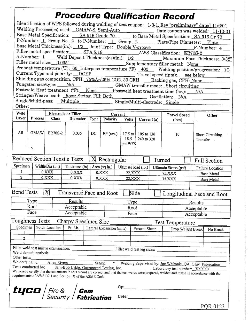
132
133
134
135
136
137
138
139
140
141
142
143
144
145
146
147
148
149
150
151
152
153 SECTION 7 MISCELLANEOUS
154
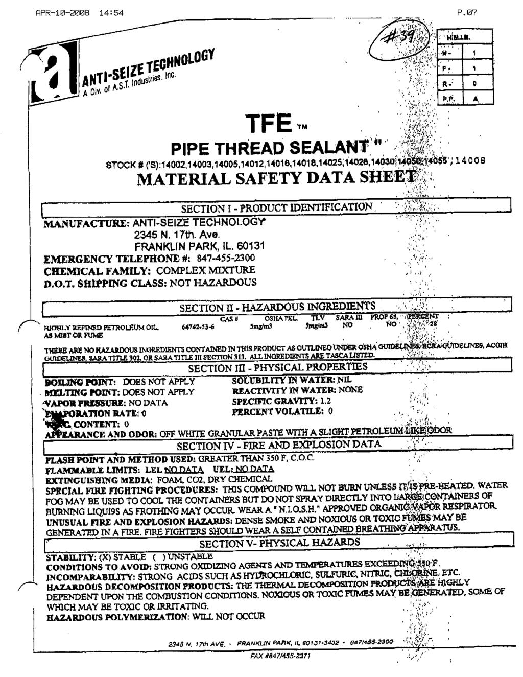
155
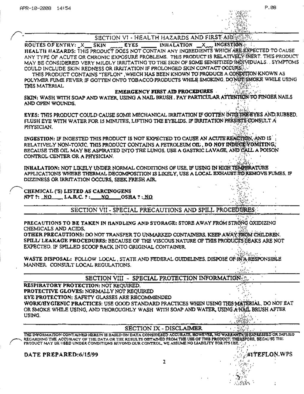
156
157
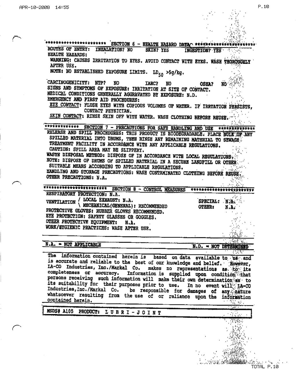
158
159
160
161
162
163
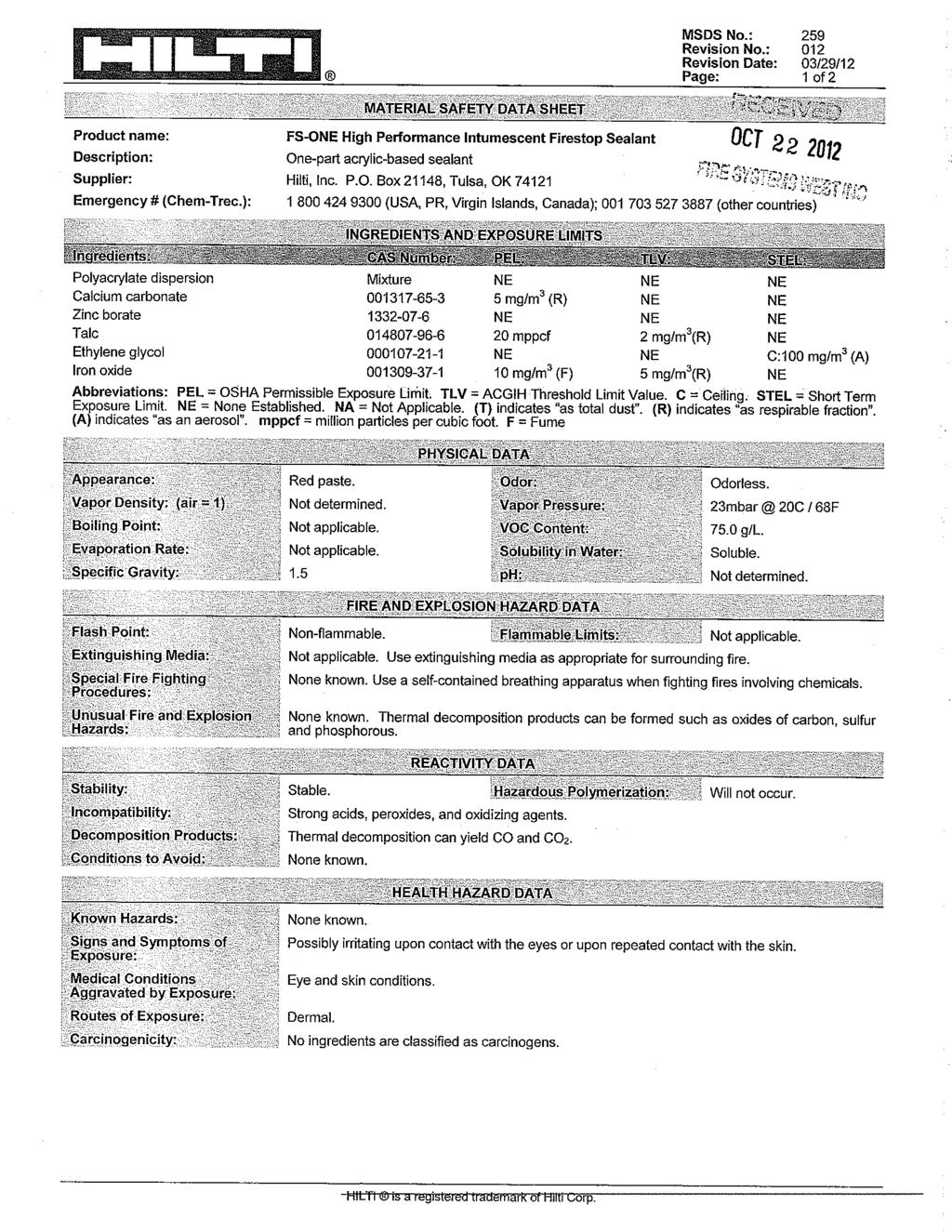
164
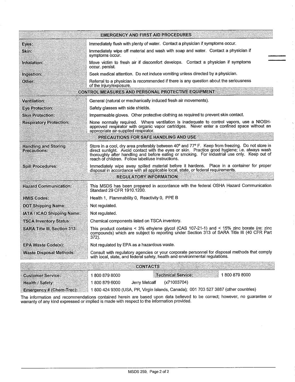
165
Grinnell Grooved Fire Protection Products Grooved Fittings
 Technical Services: Tel: (800) 38-932 / Fax: (800) 79-5500 www.tyco-fire.com Grinnell Grooved Fire Protection Products Grooved Fittings General Description LPCB Vd S The grooved fittings provide an economical
GRINNELL Model B302 and Model BN302 Grooved End Butterfly Valves with Gear Operators or Lever-Lock Operators General Description
 Technical Services -00- +-0--0 www.grinnell.com GRINNELL Model B0 and Model BN0 Grooved End Butterfly Valves with Gear Operators or Lever-Lock Operators General Description The GRINNELL Models B0 and BN0
GRINNELL MODEL CB800 CIRCUIT BALANCING VALVE INSTALLATION & SETTING HANDBOOK
 Technical Services 866-500-4768 +-40-78-8220 GRINNELL MODEL CB800 CIRCUIT BALANCING VALVE INSTALLATION & SETTING HANDBOOK AUGUST 20 IH-4500 Table of Contents Contents General Description.... 3 Dimensional
Model F822 thru F834 Mulsifyre Directional Spray Nozzles, Open, High Velocity General Description
 Technical Services: Tel: () 31-931 / Fax: () 791-55 Model F thru F3 Mulsifyre Directional Spray Nozzles, Open, High Velocity General Description The Mulsifyre Nozzles are open (nonautomatic) nozzles and
Product Submittals for Project
 Product Submittals for Project May 011-1 Couplings Figure 577 Light Weight Rigid Coupling For Fire Protection Pressure Rating and Listing / Approval information contact Tyco Fire Suppression & Building
Mechanical MATERIAL SPECIFICATIONS. Stainless Steel Housing Specifications. Gasket Specifications. Bolt / Nut Specifications
 82 COUPLINGS SYSTEM The Grinnell Stainless Steel System is designed for joining 2" to 12" (54,0mm to 206,4mm) stainless steel piping, schedules 5, 10, and 40. The Figure 472 coupling patented Universal
Couplings. Ductile Iron Housing Specifications. Coatings. Gasket Specifications. Bolt/Nut Specifications
 Figure 71 Flange Adapters (ANSI Class 5/150) The Figure 71 Flange Adapter is capable of pressures up to 300 psi (20,7 bar) depending on pipe size and wall thickness. It provides a direct transition from
The applicable material specifications for ductile iron and rubber gaskets apply:
 72 COUPLINGS - Grinnell Copper Grooved System is designed for joining copper tube size components 2" to 8" (54,0mm to 206,4mm) type K, L, M and DWV. All couplings and fittings are rated for working pressures
GRINNELL Model B302 and Model BN302 Grooved End Butterfly Valves with Gear Operators or Lever-Lock Operators General Description
 Worldwide Contacts www.grinnell.com GRINNELL Model B0 and Model BN0 Grooved End Butterfly Valves with Gear Operators or Lever-Lock Operators General Description The GRINNELL Model B0 and Model BN0 Butterfly
GRINNELL Model B303 Grooved End Butterfly Valves with Gear Operators or Lever-Lock Operators General Description
 Worldwide Contacts www.grinnell.com GRINNELL Model B Grooved End Butterfly Valves with Gear Operators or Lever-Lock Operators General Description The GRINNELL Model B Butterfly Valves provide for efficient
B U I L D I N G C O N N E C T I O N S T H AT L A S T
 B U I L D I N G C O N N E C T I O N S T H AT L A S T pipe to pipe and people to people. We pride ourselves in providing the finest-quality pipe products and services with integrity and dedication to superior
INSTALLATION & MAINTENANCE GUIDE
 BUTTERFLY VALVES INSTALLATION & MAINTENANCE GUIDE L-1 GLOBE BUTTERFLY VALVE INSTALLATION AND MAINTENANCE GUIDE Table of Contents Page Design Requirements and Installation Care and Maintenance GL175T GL175G
Model CV-1FR Grooved-End Riser Check Valves 2 Inch to 12 Inch (DN50 to DN300) General Description. Installation. Technical Data
 General Description. Installation. Technical Data") Worldwide Contacts www.tyco-fire.com Model CV-FR Grooved-End Riser Check Valves Inch to Inch (DN0 to DN00) General Description The TYCO Model CV-FR Grooved- End Riser Check Valve is a compact and rugged
Worldwide Contacts www.tyco-fire.com Model CV-FR Grooved-End Riser Check Valves Inch to Inch (DN0 to DN00) General Description The TYCO Model CV-FR Grooved- End Riser Check Valve is a compact and rugged
Manufacturing Facility is ISO9001:2000. Welded Steel Pipe Conform to ASTM A53. Threads Conform to ASME B1.20.1
 STEEL NIPPLES S40 & S80 Steel Nipple Product Specifications Manufacturing Facility is ISO9001:2000 Welded Steel Pipe Conform to ASTM A53 Threads Conform to ASME B1.20.1 800-678-2544 800-678-0857 www.msi-products.com
4077 AIRPARK DRIVE STANDISH, MICHIGAN PHONE FAX
 Butterfly Valves 4077 AIRPARK DRIVE STANDISH, MICHIGAN 48658 PHONE 989-846-4583 FAX 989-846-9231 www.globesprinkler.com FEBRUARY 2010 L-1 BULLETIN BUTTERFLY REV# 4 GLOBE BUTTERFLY VALVE INSTALLATION AND
Size Inches UL ULC FM. Pipe Sch.
 IPS CARBON STEEL PIPE - FIRE PROTECTION PRODUCTS FireLock Rigid Coupling STYLE 005 WITH VIC-PLUS GASKET SYSTEM (NORTH AMERICA ONLY) FireLock Style 005 rigid coupling has a unique, patented angle-pad design
Grooved End Fittings. System No. Submitted By Spec Sect Para Location Date Approved Date CARBON STEEL PIPE - GROOVED FITTINGS
 SEE VICTAULIC PUBLICATION 10.01 FOR DETAILS Victaulic offers a broad line of fittings in sizes through 60"/1500 in a variety of straight and reducing styles. Most standard fittings are cast of durable
GRUVLOK FITTINGS FOR GROOVED-END PIPE
 GRUVLOK FITTINGS FOR GROOVED-END PIPE Gruvlok fittings are available through 24" nominal pipe size in a variety of styles. Use the Fitting Table to convert nominal pipe size to corresponding pipe These
Carbon Steel Nipples
 CORPORATE OFFICE TEL (800) 766-0076 LOCAL (323) 890-4455 WWW.SMITHCOOPER.COM FAX (323) 890-4456 Carbon Steel Nipples Schedule 40 & 80 Welded, Schedule 80 Seamless, & XXH Seamless Carbon Steel Nipples Specifications
Grooved End Fittings. System No. Submitted By Spec Sect Para Location Date Approved Date CARBON STEEL PIPE - GROOVED FITTINGS
 SEE VICTAULIC PUBLICATION 10.01 FOR DETAILS Victaulic offers a broad line of fittings in sizes through 60"/1500 in a variety of straight and reducing styles. Most standard fittings are cast of durable
Large Capacity Aluminum Piping System
 Large Capacity Aluminum Piping System High Quality Aluminum Piping Systems Simply stated there is no equal. Elevation from Applied System Technologies (AST), has taken large diameter piping systems to
Technical Data. Sizes 2 in. to 24 in. (DN50 to DN600) Approvals UL and ULC Listed FM Approved
 Approvals UL and ULC Listed FM Approved") Worldwide Contacts www.tyco-fire.com Model TJP Resilient-Seated Gate Valves with Vertical or Cross Wall Post Indicator General Description TYCO Model TJP Resilient-Seated Gate Valves with Vertical and
Worldwide Contacts www.tyco-fire.com Model TJP Resilient-Seated Gate Valves with Vertical or Cross Wall Post Indicator General Description TYCO Model TJP Resilient-Seated Gate Valves with Vertical and
with the specific application. Always read and understand the installation
 Worldwide Contacts www.tyco-fire.com Resilient-Seated Gate Valves Outside Screw and Yoke General Description TYCO Resilient-Seated Gate Valves are used in Fire Protection Systems for on/off operation.
Grooved End Fittings. System No. Submitted By Spec Sect Para Location Date Approved Date CARBON STEEL PIPE - GROOVED FITTINGS
 SEE VICTAULIC PUBLICATION 10.01 FOR DETAILS Victaulic offers a broad line of fittings in sizes through 48 /1200 in a variety of straight and reducing styles. Most standard fittings are cast of durable
STAINLESS STEEL FORGED FITTINGS 3000lb 304/304L & 316/316L Forged Stainless Steel Fittings Product Specifications
 STAINLESS STEEL FORGED FITTINGS 3000lb 304/304L & 316/316L Forged Stainless Steel Fittings Product Specifications Manufactured in ISO9000:2000 Facility Manufactured to ASTM/ASME A182/SA182 Items conform
STAINLESS STEEL SYSTEMS
 STAINLESS STEEL SYSTEMS 139 Systems Table of Contents Figure 472 Rigid Couplings Page 142 Figure 401 45 Elbows Page 149 Figure SS-7X Rigid Couplings (Large Diameter) Page 143 Figure 405 Flexible Couplings
Grooved Piping Products
 2 Grooved Piping Products Tyco Fire Products is ISO 9001 Certified with products manufactured in our newly constructed state of the art domestic ductile iron foundry and manufacturing facilities. We are
Model 7706 Reducing Coupling. Deg. Axial Displacement
 MODEL 7706 REDUCING COUPLING The Model 7706 Reducing allows direct reduction on a piping run and eliminates the need for a concentric reducer and couplings. The specially designed rubber gasket prevents
GROOVED COUPLINGS - STANDARD FLEXIBLE Model 101
 GROOVED COUPLINGS - STANDARD FLEXIBLE Model 101 Available Sizes 1" through 12" (25 through ) Pipe Material Carbon steel, Schedule 10, Schedule 40. For use with alternative materials and wall thicknesses
FIG Gruvlok Flange Adapter
 FIG. 88 Gruvlok Adapter The Gruvlok Fig. 88 Adapter allows for direct connection of Class 125 or Class 150 flanged components to a grooved piping system. The Gruvlok Adapter provides an alternative method
HR-20P Pneumatically Controlled Pressure Regulator
 HR-20P Pneumatically Controlled Pressure Regulator Instruction and Service Manual Hydroplex Corporation 230 West Gloria Switch Rd. Lafayette, LA 70507 337-233-0626 www.hydroplexpumps.com I. General Instructions
REQUEST PUBLICATION 18.11
 * SEE VICTALIC PBLICATION 10.01 FOR DETAILS The Victaulic Pressfit 316 System for joining approved Type 316/316L stainless steel pipe provides a fast, easy, clean, reliable means for joining ½"/15, ¾"/
PVC Gasketed Fittings for PVC IPS Pressure Pipe ENGINEERED FOR DURABILITY
 For the most up-to-date version of this price list, EFFECTIVE MARCH 4, 2019 ENGINEERED FOR DURABILITY HARRINGTON CORPORATION P.O. BOX 10335 LYNCHBURG, VIRGINIA 24506-0335 For the most up-to-date version
STEEL PIPE NIPPLES - WELDED Price Sheet PNW-7.18 Effective: July 16, 2018 Cancels Price Sheet PNW-3.18 of March 5, 2018
 STEEL PIPE NIPPLES - WELDED Price Sheet PNW-7.18 Effective: July 16, 2018 Cancels Price Sheet PNW-3.18 of March 5, 2018 FOR THE MOST CURRENT PRODUCT/PRICING INFORMATION ON ANVIL PRODUCTS, PLEASE VISIT
Watts Series CSM-61. Flow Measurement/Balancing Valves Sizes: 1 1 4", 1 1 2", 2", 2 1 2", and 3" (32, 40, 50, 65 and 80mm) Installation Instructions
 Installation Instructions") Watts Series CSM-61 Measurement/Balancing Valves Sizes: 1 1 4", 1 1 2", 2", 2 1 2", and 3" (32, 4, 5, 65 and 8mm) Installation Instructions IS-CSM-61-L Watts Measurement/Balancing Valves are available
Watts Series CSM-61 Measurement/Balancing Valves Sizes: 1 1 4", 1 1 2", 2", 2 1 2", and 3" (32, 4, 5, 65 and 8mm) Installation Instructions IS-CSM-61-L Watts Measurement/Balancing Valves are available
030/TL 03/01 50M, Copyright 2001, Anvil International $3. 50
 030/TL 03/01 50M, Copyright 2001, Anvil International $3. 50 Pipe Fitter Handbook Another Anvil Advantage Mini-catalog Installation Procedures Technical Data Copyright 2001 by Anvil International, Inc.
Hole-cutting. cutting a hole. After the hole has been cut all rough edges must be removed and the area within 5/8 (16mm) of the hole
 of the hole") Mechanical Tees Hole-cutting Shurjoint mechanical tees provide a fast and easy mid-point branch outlet, eliminating the need for welding or the use of multiple fittings. The Model M21 features a female
Mechanical Tees Hole-cutting Shurjoint mechanical tees provide a fast and easy mid-point branch outlet, eliminating the need for welding or the use of multiple fittings. The Model M21 features a female
ASM Maxi Poles. Instruction-Parts B Series. For the application of architectural paints and coatings.
 Instruction-Parts ASM Maxi Poles 312483B For the application of architectural paints and coatings. 3400 Series 4050 psi (27.92 MPa, 280 bar) Maximum Working Pressure Important Safety Instructions Read
Grooved Fire Protection. Installation Handbook
 Grooved Fire Protection Installation Handbook October 2016 Grooved Fire Protection Installation Handbook OCTOBER 2016 IH-1000FP Worldwide Contacts www.tyco-fire.com GLOBAL HEADQUARTERS 1400 Pennbrook
FIG Gruvlok Flanges
 Gruvlok Flanges The Gruvlok Fig. 7012 Flange allows direct connection of Class 125 or Class 150 flanged components to a grooved piping system. The two interlocking halves of the 2" thru 12" sizes of the
COMPRESSED AIR SYSTEM 2½" TO 10" Big-Lock Tubing
 COMPRESSED AIR SYSTEM 2½" TO 10" Big-Lock Tubing High Quality Aluminum Piping Systems Simply stated there is no equal. Big-Lock from Gardner Denver has taken large diameter piping systems to a new level.
A Member of the. Integrated Metering Technologies
 I n s t a l l a t i o n M a n u a l A Member of the Integrated Metering Technologies 1.0 General and Safety Do not install, operate or maintain this flow meter without reading, understanding and followingthe
QuickVic Rigid Coupling for Steel. System No. Submitted By Spec Sect Para Location Date Approved Date CARBON STEEL PIPE GROOVED COUPLINGS
 H ONL. SEE PAGE 4 FOR DETAILS. The patented Style 107 rigid coupling joins 12"/50 300 standard roll grooved and cut grooved steel pipe. The joint is assembled without disassembling the bolts, nuts, gasket
SECTION COMMON WORK RESULTS FOR FIRE SUPPRESSION. A. Pipe, fittings, valves, and connections for sprinkler systems.
 SECTION 210500 - COMMON WORK RESULTS FOR FIRE SUPPRESSION PART 1 GENERAL 1.1 SECTION INCLUDES A. Pipe, fittings, valves, and connections for sprinkler systems. 1.2 RELATED REQUIREMENTS A. Section 099000
DeZURIK 2-24 (50-600mm) KGN-RSB BI-DIRECTIONAL CAST STAINLESS STEEL KNIFE GATE VALVES
 KGN-RSB BI-DIRECTIONAL CAST STAINLESS STEEL KNIFE GATE VALVES") 2-24 (50-600mm) KGN-RSB BI-DIRECTIONAL CAST STAINLESS STEEL KNIFE GATE VALVES Instruction D11023 October 2016 Instructions These instructions provide information about KGN-RSB Knife Gate Valves. They are
2-24 (50-600mm) KGN-RSB BI-DIRECTIONAL CAST STAINLESS STEEL KNIFE GATE VALVES Instruction D11023 October 2016 Instructions These instructions provide information about KGN-RSB Knife Gate Valves. They are
Model RM-1 Riser Manifold Commercial and Residential General Description
 Worldwide Contacts www.tyco-fire.com Model RM- Riser Manifold Commercial and Residential General Description The TYCO commercial and residential Model RM- Riser Manifold provide the necessary waterflow
Stainless Steel Pipe System. System No. Submitted By Spec Sect Para Location Date Approved Date TEMPERATURE ( F/ C)
") The Victaulic Vic-Press 304 System for joining approved Type 304/304L stainless steel pipe provides a fast, easy, clean, reliable means for joining 1/2"/15, 3/4"/20, 1"/25, 1 1/2"/40, and 2"/50 stainless
The Victaulic Vic-Press 304 System for joining approved Type 304/304L stainless steel pipe provides a fast, easy, clean, reliable means for joining 1/2"/15, 3/4"/20, 1"/25, 1 1/2"/40, and 2"/50 stainless
TAPPING & SERVICE SADDLES
 TAPPING & SERVICE SADDLES The Standard of Excellence in the Industry CS12 CSC1 CS22 CSC2 CNS1 CDS1 CNS2 CDS2 CFS CFT-TO 1213 BADGER STREET YORKVILLE, ILLINOIS 60560 (630) 553-0840 (800) 426-4301 FAX (630)
A Member of the. Integrated Metering Technologies
 I n s t a l l a t i o n M a n u a l A Member of the Integrated Metering Technologies 1.0 General and safety Do not install, operate or maintain this flow meter without reading, understanding and followingthe
Instructions for Installation, Operation, Care and Maintenance
 Bulletin 59 Model DDX Deluge Valve (50 mm), ½ (65 mm), (80 mm), 76 mm, 4 (00 mm), 6 (50 mm), 65 mm & 8 (00 mm) Bulletin 59 Instructions for Installation, Operation, Care and Maintenance Wet Pilot Line,
DeZURIK 2 20" BOS BUTTERFLY VALVES
 2 20" BOS BUTTERFLY VALVES Instruction D10459 October 2013 2-20 BOS Butterfly Valves Instructions These instructions provide information about BOS Butterfly Valves. They are for use by personnel who are
Housing Coating: Orange enamel. Hot dipped galvanized. Optional Bolts/Nuts: (Available in imperial size bolts and nuts only.)
") SEE VICTAULIC PUBLICATION 10.01 FOR DETAILS The patented Style 107H rigid coupling joins 8"/50 200 standard roll grooved and cut grooved steel pipe.* The joint is assembled without disassembling the bolts,
SEE VICTAULIC PUBLICATION 10.01 FOR DETAILS The patented Style 107H rigid coupling joins 8"/50 200 standard roll grooved and cut grooved steel pipe.* The joint is assembled without disassembling the bolts,
Fire Protection Valves
 Fire Protection Valves 1002 C O N T E N T S Terms and Conditions - Page 30 Angle Valves... 7-9 Ball Valves... 1-3 Ball Drip Valves...18 Check Valves, Grooved (Ductile)... 29 Check Valves, Screwed (Ductile)...28
Section 2. Shurjoint Grooved Fittings Flow Data / Friction Resistance Ductile Iron Grooved Fittings. Wrought Grooved Fittings
 Section 2 Cast & Wrought Grooved Fittings Shurjoint Grooved Fittings... 56 Flow Data / Friction Resistance... 56 Ductile Iron Grooved Fittings 7110 / 7111 / 7112 / 7113 Elbows... 57 7120 / 7135 / 7130
DeZURIK KUL KNIFE GATE VALVES
 KUL KNIFE GATE VALVES Instruction D11025 September 2013 Instructions These instructions are intended for personnel who are responsible for the installation, operation and maintenance of your KUL knife
Access Doors. Sandwich Access Doors. Quick and Easy
 D U C T M A T E Access Doors Sandwich Access Doors Quick and Easy Advanced Pressure Vessel Design Insulated, Uninsulated, and Specialty Metals No Measuring (Self-Adhesive Template Provided) Effortless
Pipe hanger solutions
 Product catalog Middle East offering Pipe hanger solutions for commercial and industrial applications B00 series B00 - Standard clevis hanger Pipe will not pinch when installing. 5 swing in either direction
SCHEDULE 80 PVC PRESSURE FITTINGS L80P EFFECTIVE JULY 1, 2017 REVISED PRODUCTS PRICE LIST INCLUDES: SCHEDULE 80 PVC 1/4 TO 12
 PRICE GROUP DESCRIPTION 02 SCH 80 PVC through 8 92 SCH 80 PVC 10" AND LARGER VB GASKET for FLANGE DISCOUNT MULTIPLIER PRODUCTS SCHEDULE 80 PVC PRESSURE FITTINGS INCLUDES: SCHEDULE 80 PVC 1/4 TO 12 L80P
INTERNATIONAL MALLEABLE IRON PIPE FITTINGS & UNIONS
 INTERNATIONAL MALLEABLE IRON PIPE FITTINGS & UNIONS PRICE SCHEDULE #101016 EFFECTIVE: OCTOBER 1, 2016 MADE IN BRAZIL, UNLESS NOTED 117 Gulick Street, Blossburg, PA 16912 www.wardmfg.com (800) 248-1027
JOHN DEERE 9970 COTTON PICKERS
 PARTS CATALOG FOR Mud Hog System II Rear Wheel Drive FOR JOHN DEERE 9970 COTTON PICKERS Mud Hog Model Numbers Tread Center OEM Aftermarket JD40005 JD47655 82, 90, 94, 106 TUTHILL Drive Systems 9098 West
Installation, Operation and Maintenance of Airflex Model AA2, B2, B3 and C2 Rotorseals
 RS 9010 Warning Forward this manual to the person responsible for Installation, Operation and Maintenance of the product described herein. Without access to this information, faulty Installation, Operation
11.02 Mechanical-T Bolted Branch Outlets
 STLES AND SEE ICTAULIC PUBLICATION 10.01 FOR DETAILS NIIPO ictaulic Mechanical-T Outlet provides a direct branch connection at any location a hole can be cut in pipe. The hole is cut oversize to receive
WARRANTY POLICY. Grid-Tied Photovoltaic Inverters. Revision D. 2014, Solectria Renewables, LLC DOCIN
 WARRANTY POLICY Revision D 2014, Solectria Renewables, LLC DOCIN-070360 1 Product Warranty & RMA Policy 1. Warranty Policy Warranty Registration: It is important to have updated information about the inverter
Pressure Roller with 24-inch Fixed Extension - For application of architectural paints and coatings -
 Instructions Important Safety Instructions Read all warnings and instructions in this manual. Save these instructions. 311082D Pressure Roller with 24-inch Fixed Extension - For application of architectural
TBM Series 3-Way Ball Valve
 www.simtechusa.com TBM Series 3-Way Ball Valve Operating, Installation, & Maintenance Manual Corrosion Resistant Fluid and Air Handling Systems. Dated 06-26-13 TBM Series Ball Valves SIMTECHRECOMMENDSREADINGTHEFOLLOWINGINFORMATIONPRIORTOINSTALLINGANDUSING
GC-1. Roof and Gutter De-Icing Control Installation and Operating Instructions FOR EXTERIOR INSTALLATION ONLY
 GC-1 Roof and Gutter De-Icing Control Installation and Operating Instructions FOR EXTERIOR INSTALLATION ONLY GENERAL INFORMATION The GC-1 heating cable controller has been designed and manufactured for
FireLock NXT Deluge Valve. With Deluge Trim Grooved x Grooved. System No. Submitted By Spec Sect Para Location Date Approved Date
 MEA: 248-98-E CSFM: 7770-0531-117 The patent-pending Victaulic Series 769 FireLock NXT controls the water supply entry into the deluge system piping and open sprinklers. The Series 769 is a low differential,
DAP-625S and DAP-875S
 AIR CHAMP PRODUCTS DAP-625S and DAP-875S (i) FORM NO. L-20078-B-0501 In accordance with Nexen s established policy of constant product improvement, the specifications contained in this manual are subject
Strainer and Check Valves
 Strainer and Check Valves Quality Valves at Low Cost Table of Contents Strainer and Check Valves 125# Cast Iron Y Strainer Flanged...3 125# Cast Iron Double Door Check Valve...4 Single Flapper Wafer Check
Parts Manual Vermeer/ McLaughlin Mud System 230P
 2006 Perimeter Road. Greenville, SC 29605 Toll Free: 800/435-9340 - Phone: 864/277-5870 Fax: 864/235-9661 - Website address: www.mightymole.com Email address: mmole@mightymole.com Parts Manual Vermeer/
INLINE FOAM INDUCTOR HD FIRE PROTECT PVT. LTD. TECHNICAL DATA DESCRIPTION SPECIFICATION APPLICATION SYSTEM DESIGN DETAILS
 INLINE FOAM INDUCTOR HD FIRE PROTECT PVT. LTD. TECHNICAL DATA MODEL OPERATING PRESSURE IG - Bronze material IS - Stainless Steel material 6.5 to 12 BAR (93-175 PSI) FACTORY 25 BAR (365 PSI) HYDROSTATIC
Installation Instructions
 Primary Brake Pin Drive Armature PB-825, PB-1000, PB-1225, PB-1525 Motor Brake and Spline Drive MB-825, MB-1000, MB-1225 Pin Drive P-208 819-036 Installation Instructions Contents Installation Instructions
AMERICAN AVK COMPANY TABLE OF CONTENTS
 AMERICAN AVK COMPANY AVK SERIES 815 BUTTERFLY VALVE FIELD MAINTENANCE AND INSTRUCTION MANUAL FOR UL/FM APPROVED IPS - GROOVED END BUTTERFLY VALVES 2½" - 8" TABLE OF CONTENTS EXPLODED ASSEMBLY / PARTS LIST
TB Series Brakes Tension Control System
 TB Series Brakes Tension Control System P-235-WE Service & Installation Instructions An Altra Industrial Motion Company Contents Installation Instructions...3 Coil Data...4 Maintenance...5 Control Connections...5
HDPE HIGH DENSITY POLYETHYLENE PRODUCTS
 HDPE HIGH DENSITY POLYETHYLENE PRODUCTS The Standard of Excellence in the Industry CPS-IPS PECST-SL PECR1 PECR2 PECS- PECS-22 PECSC-1 PECSC-2 CERTIFIED TO NSF/ANSI 1 13 BADGER STREET YORKVILLE, ILLINOIS
Commercial Ball Valves
 Price Schedule C-01-18 January 1, 2018 Supersedes C-06-15 Commercial Ball Valves BRASS & BRONZE BALL VALVES TWO-PIECE BODY $ 10.95 0.27 20 120 10.95 0.29 20 120 012 10.10 0.38 12 96 034 13.90 0.58 10 60
V150 VERIS Verabar Installation and Maintenance Manual
 V150 VERIS Verabar Installation and Maintenance Manual 164-EN Please read and save these instructions Contents General Safety Information...3 Product Information...3 Section 1: Scope...3 Purpose of this
Innerlynx Type UL Fire Rated 3Hour Fire Stop ADVANCE PRODUCTS & SYSTEMS, INC. ISO-9001 CERTIFIED COMPANY - FM
 Innerlynx Type UL Fire Rated 3Hour Fire Stop ADVANCE PRODUCTS & SYSTEMS, INC. ISO-9001 CERTIFIED COMPANY - FM53705 www.apsonline.com Why choose Innerlynx? offer 21 different sizes for all pipe diameters
Mechanical Piping.
 Mechanical Piping www.anvilintl.com JULY 2016 For the most current product/pricing information on Anvil products, please visit our website at www.anvilintl.com BUILDING CNNECINS HA LAS For over 160 years,
DV-5a Automatic Water Control Valve Single Interlock Preaction Fire Protection Systems 1-1/2 Inch to 8 Inch (DN40 to DN200) General Description
 General Description") Worldwide Contacts www.tyco-fire.com DV-5a Automatic Water Control Valve Single Interlock Preaction Fire Protection Systems 1-1/ Inch to Inch (DN40 to DN00) General Description The TYCO DV-5a Automatic
Worldwide Contacts www.tyco-fire.com DV-5a Automatic Water Control Valve Single Interlock Preaction Fire Protection Systems 1-1/ Inch to Inch (DN40 to DN00) General Description The TYCO DV-5a Automatic
ORDERING: Specify size, figure number, description, nominal pipe size or special O.D. and C-to-C dimension. C - C LOAD lb.
 Fig. 2110 www.pipingtech.com/fig2110 Sway Strut with 4 of Adjustment Engineered spring supports option 1 option 2 ORDERING: Specify size, figure number, description, nominal pipe size or special O.D. and
Parts Manual Vermeer/ McLaughlin Mud System 230P
 2006 Perimeter Road. Greenville, SC 29605 Toll Free: 800/435-9340 - Phone: 864/277-5870 Fax: 864/235-9661 - Website address: www.mightymole.com Email address: mmole@mightymole.com Parts Manual Vermeer/
30.85 FireLock NXT Actuated Valve with LPCB Approved Preaction Trim
 Actuated Valve with LPCB Approved Preaction Trim 104g/01 with: - Electric Activation with Redundant Solenoid Valve - Electric Activation with Redundant Solenoid Valve and AutoConvert Dry Trim - Double
Brass, Bronze, Iron and Stainless Steel Valves
 Price Schedule January 1, 2018 Supersedes BIV-06-15 Brass, Bronze, Iron and Stainless Steel Valves 07 BRONZE GATE VALVES CLASS 125 ASTM B283 FORGED BRASS SCREW-IN BONNET NON-RISING STEM SOLID WEDGE DISC
Series 756 FireLock Dry System Check Valve
 R IPS CARBON STEEL PIPE FIRE PROTECTION PRODUCTS Series FireLock Dry System Check Valve Grooved X Grooved and Flanged X Grooved 0.0 VICTAULIC IS AN ISO 900 CERTIFIED COMPANY PRODUCT DESCRIPTION The Victaulic
Installation, Operation and Maintenance of the Airflex Model BT Rotorseal Assembly
 RS 9070 Warning Forward this manual to the person responsible for Installation, Operation and Maintenance of the product described herein. Without access to this information, faulty Installation, Operation
PVI 1800/PVI Residential/Commercial Grid-Tied Photovoltaic Inverter WARRANTY MANUAL. Subject to Change REV , Solectria Renewables
 PVI 1800/PVI 2500 WARRANTY MANUAL Residential/Commercial Grid-Tied Photovoltaic Inverter 2009, Solectria Renewables Subject to Change REV 10.09 1 Product Warranty & RMA Policy 1.1 Warranty Policy The Solectria
INTRODUCTION INSTALLATION
 INTRODUCTION INSTALLATION, OPERATION & MAINTENANCE INSTRUCTIONS This instruction manual includes installation, operation and maintenance information for the figure G73 gear operator. The figure G73 is
Single-Position Detent Clutch DC Series. (i) MTY (81) MEX (55) QRO (442)
 MTY (81) MEX (55) QRO (442)") Single-Position Detent Clutch DC Series (i) FORM NO. L-2017-A-001 In accordance with Nexen s established policy of constant product improvement, the specifications contained in this manual are subject
Single-Position Detent Clutch DC Series (i) FORM NO. L-2017-A-001 In accordance with Nexen s established policy of constant product improvement, the specifications contained in this manual are subject
Listings and Approvals. G5 QR Gasket culus QR G5 SR Gasket culus, FM SR G5
 Model Series Sprinklers Available with Solid, Perforated, or Gasket Standard Coverage, Concealed Pendent K2.8, 4.2, 5.6, & 8.0 (40, 60, 80, & 115 metric) Features Flat concealed cover plate available solid
DOMESTIC FIRE PRODUCTS
 DOMESTIC FIRE PRODUCTS Price Sheet GR.FP-8.16 Effective August 15, 2016 Cancels Price Sheet GR.FP-7.15 of July 6, 2015 FOR THE MOST CURRENT PRODUCT / PRICING INFORMATION ON ANVIL PRODUCTS, PLEASE VISIT
September 2012 / M&H C502 / Model 129
 GENERAL FEATURES / GENERAL SPEC M&H AWWA C502 FIRE HYDRANTS Model 129 Traffic Model 250 PSI Working Pressure 500 PSI Hydrostatic Test AWWA UL / FM Approved Type: Compression type, opening against line
APCO CRF-100A RUBBER FLAPPER SWING CHECK VALVES
 APCO CRF-100A RUBBER FLAPPER SWING CHECK VALVES Instruction D12043 June 2016 DeZURIK Instructions These instructions provide installation, operation and maintenance information for APCO CRF-100A Rubber
A. This Section includes natural gas piping, specialties, and accessories within the building.
 SECTION 226313 NATURAL GAS PIPING PART 1 - GENERAL 1.1 RELATED DOCUMENTS A. Drawings and general provisions of the Contract, including General and Supplementary Conditions and Division 01 Specification
Approved Branded Traceable Fire Protection & Waterworks Valves
 Approved Branded Traceable Fire Protection & Waterworks Valves (800) 766-0076 www.smithcooper.com Los Angeles, CA Atlanta, GA Vancouver, WA Chicago, IL AWWA C515 Compliant CONSIDER Your Options Tamper
Terms and Conditions
 Terms and Conditions GUARANTEE: All Brighton-Best International, Inc. products are manufactured to rigid quality control standards which meet or exceed industry standards. Records and tests pertaining
SOLUTION DISTRIBUTORS BOOK NO. IM AA UA
 SOLUTION DISTRIBUTORS BOOK NO. IM 50.320AA UA ISSUE A EQUIPMENT SERIAL NO. DATE OF START-UP START-UP BY Prompt service available from nationwide authorized service contractors. ORDERING INFORMATION In
FCB-450, LCB-600, MCB-800
 AIR CHAMP PRODUCTS User Manual FCB-450, LCB-600, MCB-800 Clutch-Brakes (i) In accordance with Nexen s established policy of constant product improvement, the specifications contained in this manual are
Ford Brass Saddles Style 101B and 202B
 101B Ford Brass Saddles 101B and 202B 101B, 3/4" and 1" Taps 202B, 3/4" through 2" Taps Specifications Body - 85-5-5-5 brass alloy as per ASTM B62, ASTM B584 and AW WA C800. Threads may be FIP, AW WA,