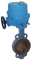
Operation and Installation Manual Ball Valves
|
|
|
- Betty Cross
- 6 years ago
- Views:
Transcription

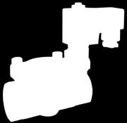
1 Operation and Installation Manual Ball Valves END-Armaturen GmbH & Co. KG Oberbecksener Str. 78 D Bad Oeynhausen Telefon (05731) Telefax (05731)
2 Impressum by END-Armaturen GmbH & Co. KG All rights reserved. END-Armaturen GmbH & Co. KG claims copyright over this documentation. This documentation may neither be altered, expanded, reproduced nor passed to third parties without the written agreement of END-Armaturen GmbH & Co. KG. This restriction also applies to the corresponding drawings. END-Armaturen GmbH & Co. KG has the right or change parts of the valves and armatures at any time without prior or direct notice to the client. The contents of this publication are subject to change without notice. This publication has been written with great care. However, END-Armaturen GmbH & Co.KG cannot be held responsible, either for any errors occuring in this publication or for their consequences. The products are specified by the statements in this documentation; no assurance or the properties is given. END-Armaturen GmbH & Co. KG Oberbecksener Straße 78 D Bad Oeynhausen Telefon: / Telefax: / Internet: post@end.de Edition: 07/ /2016
3 Contents Inhalt 1 Foreword 4 2 General advice Validity Inward monitoring Complaints Warranty Symbols and their signification 6 3 Safety advice Personal advice Safety advices for mounting Safety advice for adjustment / starting Safety advice for maintaining / repairing Device safety 9 4 Name-plate 10 5 Ball valves General Corresponding use Operation Mounting / Disassembly Mounting with threaded connection Mounting with welded connection Disassembly of the center part of the ball valve Welding of the connection ends Mounting of the center part Mounting with flanged connection Maintenance Readjusting of the gland Exchange of the ball and the sealing part ball valve with threaded or welded connection Multiple part ball valve with flanged connection 22 07/
4 Foreword 1 Foreword Dear customer, Dear assembler / user, these operation and installation manuals are intended to give you the knowledge, which is necessary for you to be able to carry out the mounting and adjustment of the ball valves rapaidly and correctly. Please read these instructions carefully and pay particular attention to the advice and warning notes. Only instructed and qualified mechanician should mount, adjust or maintain the ball valves. If you have any questions in relation to the ball valves we shall be pleased to answer them. The telephone number will be found on the inside cover of these operation and installation manual. Yours END-Armaturen GmbH & Co. KG /2016
5 General advice 2 General advice 2.1 Validity These mounting and installation manual is valid for the standard version of the ball valves. 2.2 Inward monitoring Please check directly after delivery the ball valves for any transport damages and deficiencies. with reference to the accompanying delivery note the number of parts. Do not leave any parts in the package. 2.3 Complaints Claims for replacement or goods which relate to transport damage can only be considered valid if the delivery company is notified without delay. In case of returns (because of transport damage / repairs), please make a damage protocol and send the parts back to the manufacturer, if possible in the original packaging. In case of a return, please mention the following: Name and address of the consignee Stock-/ ordering-/ article-number Description of the defect 2.4 Warranty For our ball valves we give a guarantee period in accordance with the sales contract. The end of the normal duration of life of the wearing parts represents no defect. The warranty and guarantee rules of END-Armaturen GmbH & Co. KG are applicable. 07/
6 Symbols and their signification 2.5 Symbols and their signification Paragraphs which are identified with this symbol contain very important advices; this also includes advices for averting health risks. Observe these paragraphs without fail! Paragraphs which are identified with this symbol contain very important advices, this also includes how to avoid damage to property. Observe these papgraphs without fail! This symbol indicates paragraphs which contain comments / advices or tips. This spanner identifies the description of actions which you should carry out /2016
7 Safety advice 3 Safety advice Depending on the technical circumstances and the time under and at which the armatures and valves are mounted, adjusted and commissioned, you must take into account particular safety aspects in each case! If, for example, a pneumatic actuator works a slide in an operational chemical plant, the potential hazards of commissioning have another dimension from that when this is only being carried out for test purposes an a dry part of the plant in the assembly room! Since we do not know the circumstances at the time of the mounting/adjustment/commissioning, you may find advices on hazards in the following descriptions which are not relevant to you. Please observe (only) the advices which applies to your situation! 3.1 Personal advice Safety advices for mounting We wish to point out expressly that the mounting, adjusting and at accessories the pneumatical and eletrical installation of the armatures and valves must be carried out by trained specialist personnel having mechanical, pneumatical and electrical knowledge! Secure that the machine / plant come up to the Machinery Directice after the mounting and installing of the armatures and valves. Switch off all the devices / machines / plant affected by mounting or repair. If appropriate, isolate the devices / machines / plant from the mains. Check (for example in chemical plants) whether the switching off of devices / machines / plant will cause potential danger. If appropriate, in the event of a fault in the armature / valve (in a plant which is in operation) inform the shift forman / safety engineer or the works manager without delay about the fault, in order, for example, to avoid an outflow / overflow of chemicals or the discharge of gases in good time by means of suitable measures! Before mounting or repairing, remove the pressure from pneumatic / hydraulic devices / machines / plant. If necessary, set up warning signs in order to prevent the inadvertent starting up of the devices / machines / plant. Observe the respective relevant professional safety and accident prevention regulations when carrying out the mounting / repair work. Check the correct functioning of the safety equipment (for example the emergency push off buttons/ safety valves, etc)! Safety advice for adjustment / starting As a result of the starting (pneumactic, electric or by hand) of the armatures and valves the flow of gases, steam, liquids, etc. may be enabled or interrupted! Satisfy yourself that, as a result of the starting or the test adjustment no potential hazards will be produced for the personnel or the environment! 07/
8 Safety advice If necessary, set up warning signs in order to prevent the inadvertent starting up or shutting down of the device / machine / plant.! By ending the adjustment check the correct function and should the occasion arise the position of the slide / valve / flap. Check the function of the limit switches (option)! Check, whether the slide / valve / flap will be closed totally, if the control signals the appropriate limit stop! Through suitable measures, prevent links being trapped by moving actuating elements! Check the right function of all safety devices (for example emergency push off buttons / safety valves)! Carry out the starting and the adjustments only in accordance with the instructions discribed in this documentation! Adjusting switch on armatures and valves with options (e.g. actuators, solenoid valves, limit switches) there is the risk that live parts (230 V AC~) can be touched! Therefore the adjustments must be carried out only by the electrican or a person having adequate training, who is aware of the potntial hazard! Safety advice for maintaining / repairing Do not carry out any maintenances / repairs if the armature / valve will be under pressure. Before disassembling or a armature or valve some essential points should be clarified! Will the armature/valve to be disassembled be replaced by another immediately? If appropriate, does the production process of the plant needed to be stopped? Is it necessary to inform specific personnel about the disassmbly? If necessary, inform the shift foreman/ safety engineer or the manager about the maintenance or repair without delay in order, for example, to avoid an outflow/ overflow of chemicals or a discharge of gases in good time by means of suitable measures! Observe that some valves / armatures are able to enclose the pressured medium e.g. the ball in the ball valve. You have to relieve the pressure in the pipes in which the armture/valve is mounted. Switch off pilot pressure and the power supply and relieve the pressure in the pipes. If necessary set up warning signs in order to prevent the inadvertent starting up of the devices/machines/plants in which the armature/ valve is mounted the switching on of pilot medium supply, pilot power supply and/or the power supply of actuators and accessories. In case of defect in the armature/valve make contact to the supplier. The telephone number will be found on the back cover of these mounting and installation manual /2016
9 Safety Advice If you ascertain a damage of the armature/valve, isolate the device from the mains. Please observe the safefy advices. Do not mount, start or adjust the armature/valve if itself, the pipes or a mounted actuator will be damaged. After the maintenance or repair check the right function of the armature/valve and the tightness of the pipe connections. Also check the function of the accessories e.g. actuators, limit switches, etc. 3.2 Device safety The armatures/valves are quality products which are produced in accordance to the recognized industrial regulations. left the manufacturer`s work in a perfect safety condition. In order to maintain this condition, as installer / user you must carry out your task in accordance with the description in these instructions, technically correctly and with the greatest possible precision. We assume, as a trained specialist you are having mechanical and electrical knowledge! Satisfy yourself that the armatures/vales will only be used within their admissible limiting value (see the technical data). The armatures/valves must be used only for a purpose corresponding to their construction! The armatures/valves must be used within the values specified in the technical data! The operating of the armature/valve outside the nominal temperature range could destroy the sealings and the bearings. The operating of the armatures/valves outside the nominal pressure range could destroy the inner parts and the body. Never remove a cap or a other component part if the armature/valve will be under pressure. Do not mount, start or adjust the armature/valve if itself, the pipes or a mounted actuator will be damaged. After the maintenance or repair check the right function of the armature/valve and the tightness of the pipe connections. Also check the function of the accessories e.g. actuators, limit switches, etc. 07/
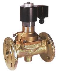
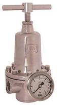
10 Name-plate 4 Name-plate In some cases the armatures/valves will be provided with a name- plate, which permitts a definite identification of the armatures/valves and shows the most important technical data to you. The name-plate should not be displaced or changed END-Armaturen GmbH & Co. KG D Bad Oeynhausen +49 (0) Art. No.: AE Serial: Pressure range (PS): 16 bar Pilot pressure: - bar Temperature range (TS): -20 C C Size (DN): 50 / G2" Testing pressure (PT): 60 bar Fluidgroup: 1 Date of manufacturing: Fig Name-plate Art.No. Serial Pressure range (PS) Pilot pressure Size (DN) Testing pressure (PT) Fluidgroup Date of manufacturing article number of the valve / armature order- or production- number max. admisable working pressure of the valve / armature [bar] recommend pilot pressure for correct function of the valve / armature [bar] (only at pneumatic actuated valves / armatures) connecting size of the valve / armature testing pressure of the body of the valve / armature allowed fluidgroup of the valve / armature month and year of manufacturing of the valve / armature /2016
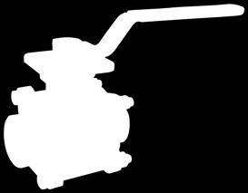
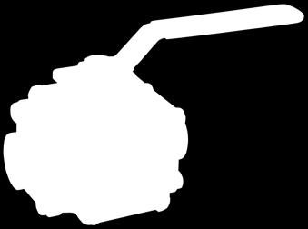
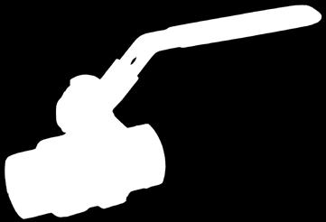
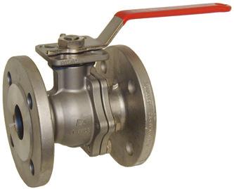
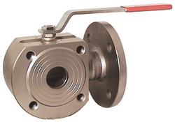
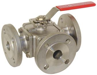
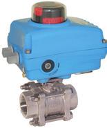
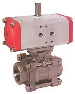
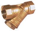
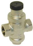
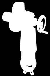
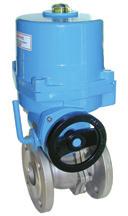
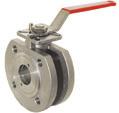
11 Ball Valves 5 Ball valves 5.1 General Before you are mount, adjust, start, operate or disassemble a ball valve you have to read the Safety advices If you have not read the safety advices until now, read this important advices now and turn back to this point. 5.2 Corresponding use Ball valves will be used to cut off medium flow. It should only be used clean liquids and gases, on which the material of the ball valve will be resistant. Pollution or using outside the nominal pressure range and/or the nominal temperature range should causes damages on the armature especially on the seals. In some cases you have to install an equalization boring into the ball, that there will be no overpressure between the body and the ball by changing temperatures. 5.3 Operation The ball valve will be open or close totally by using a handle or an pneumatic or electric actuator (option). During the operation of the ball valve take care that there won`t be insert any objects or limbs into the armature. Heavy injuries or damages will be the consequence. If it is necessary you have to install a protective device. 5.4 Mounting / Disassembly The mechanical installation will be same at all variants of the ball valve. There will be differences in the type of connection. Observe the flow direction: the handle should point at the flow direction. Remove the package and the safety devices (e.g. caps or plugs). Take care that there will be no parts of the package or other parts in the armature. Clean up the pipes in which the ball valve will be mounted. Pollution could affect the safety in operation and the duration of life of the armature. If necessary you have to install a Y- strainer in front of the ball valve. Avoid stress in case of non align pipes. 07/
12 Ball valves Mounting with threaded connection Before lay on sealing compounds, check the hardly screwing by the pipes into the valve body. Lay on the correct sealing compounds on the pipes end. By using PTFE-ribbon or hemp sealings observe the screw direction. Don`t use sealing compounds which are not prescribed for your employment. Screw the pipes into the connection ends of the valve. Don`t use the handle as a lever. Strike up the pipes with pressure after that time the manufacturer of the sealing compounds pretends to harden it. Check the tightness of all connections. sealing compound harden o.k. flow direction Fig ball valves, mounting threaded connection (Fig.: Art. TB111025) /2016
13 Ball valves Mounting with welded connection Before welding you have to disassemble the center part of the ball valve to prevent the sealings from damages Disassembly of the center part of the ball valve Clamp the valve between a vice carfully. By using guard plates you can prevent the damage of the ends of the body. Loosen the nuts crossvice and remove the screws out of the body. Take the center part of the ball valve. Observe, that you didn t drop the sealings or the ball. Put the parts aside carefully. To attach the center parts and the connection ends at a later mounting you can sign the parts. END-Armaturen GmbH & Co. KG Bad Oeynhausen Germany post@end.de AUF OPEN ZU CLOSE Fig ball valves, mounting welded connection, disassembly of the center part (Fig.: Art. ZE311064) 07/
14 Ball Valves Welding of the connection ends The center part of the ball valve must be substitute by a distance part as long as the center part during the welding. By welding the valve body with the pipes observe appropriate demands and guide lines. The safety demands by welding are depending on the place and the position of the point of weld. Welding the parts at a serviceable device/machine/plant the potential of danger is as higher as welding the parts in a welding room. If appropriate, inform the shift foreman/safety engineer or the works manager and the fire brigade of your factory. By welding observe your own national guide lines about safety and pevention of accidents. Fig ball valves,mouting welded connections, welding of the connection ends(fig.: Art. ZE311064) /2016
15 Ball valves Mounting of the center part Before mounting the center part let the connection ends cool down. Disassemble the distance part. Insert the center part between the connection ends. Attach the center parts to the right connection ends. Observe the correct seat of the sealings and that there will be no pollution in the seats of the sealings and in the ball. Insert the screws into the borings of the connection ends.tighten the nuts equally and crosswise. Observe the max. torque of the screws. Check the function of the ball valve. Check the tightness of all connections. AUF OPEN ZU CLOSE END-Armaturen GmbH & Co. KG Bad Oeynhausen Germany cool down! o.k. flow direction Fig ball valves, mounting welded connections, mounting of the center part of the ball valve (Fig.: Art. ZE311064) 07/
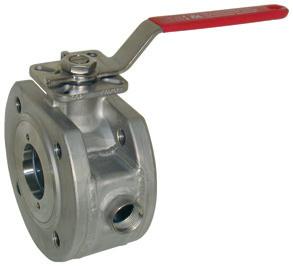
16 Ball valves Mounting with flanged connection In the following discription we assume that you have mounted the flanges at the end of the pipes and the ball valve (welded flanges) and they are cooled down. Insert the ball valve and the flange sealings between the flanges. Align the flange borings und put fit screws through the borings. Put fit nuts on the screws and tighten them equally and crossvice. Observe the required and the max. torque of the ball valve, the flanges, the flanges seals and the screws. Check the tightness of all connections. END-Armaturen GmbH & Co. KG Bad Oeynhausen Germany cool down! AUF OPEN ZU CLOSE o.k. flow direction Fig ball valves, mounting flanged connection (Fig.: Art. ZP311007) /2016
17 Ball valves 5.5 Maintenance Before you maintain or shut down the valves you have to read the Safety advice If you have not read the safety advices until now, read this important advices now and turn back to this point. On normal accounts the ball valve is maintenance free.in periodical turns the controlling of the function and the tightness should happen: check the tighness of the gland check the tightness of the ball seats Depending on the version of the ball valve for decreasing tightness at the stem the gland could be readjust. See also chapter Readjusting of the gland. Ball valves in a multiple part design could be disassemble to exchange the seals and/or the ball. See also chapter: Exchange of the ball and the sealings. In case of a defect of the valve make a contact to the supplier. The telephone number will be found on the back or these operation and installation manual. If you ascertain a demage of the valve switch off the device/ machine/ plant! However before doing this, it is essential to refer to the Safety advice. 07/
18 Ball valves Readjusting of the gland For decreasing tightness at the stem the gland could be readjust. By keeping the nominal pressure you have to tighten up the screw of the gland until the tightness of the the gland will be restored After the readjusting the ball of the valve must be able to move slightly. At ball valves with spring forced sealings or o-ring sealings at the stem the readjustment isn`t necessary. o.k. tightness Fig ball valves, readjusting of the gland (Fig.: Art. ZE311064) /2016
19 Ball valves Exchange of the ball and the sealing For decreasing tightness the ball and/or the sealings of the ball valve could be exchange. The availability of the spare parts kit you can see in the data sheet of your ball valve. Corresponding to the wear of the parts exchange the sealings and the ball. By the replacement of the ball you should also exchange the sealing. In the following description we assume, that your ball valve will be actuated by hand. If your ball valve will be actuated be a pneumatic or electric actuator, please also observe the opration and installation manual of the actuator. Cut off the media flow and relieve the media pressure. Keep ready some fit tanks to catch up leaking liquids. If it`s necessary remove the additional limt switches and gear boxes part ball valve with threaded or welded connection At 3-part ball valve it will do when you remove the center part of the ball valve. Loosen the nuts crosswise and remove the screws out of the body. Take the center part of the ball valve. Observe, that you didn t drop the sealings or the ball. Put the parts aside carefully. END-Armaturen GmbH & Co. KG Bad Oeynhausen Germany post@end.de AUF OPEN ZU CLOSE Fig ball valves, replacement of the sealing kit: removement of th center part (Fig.: Art. ZE311064) 07/
20 Ball valves Observe that ball valves could enclose medium inside the ball. Take the parts aside carefully. Place a mark on the body and the connection ends that you will be able to join the correct parts by a subsequent mounting. Remove the ball seals and the ball out of the body. Perhaps you have to turn the handle to remove the ball out of the body. Do not insert any limbs into the ball valve. Heavy injuries will be the consequences. Loosen the nut of the handle and take the handle and all discs und washers aside. Depending on the version of the ball valve loosen the nut on the stem or loosen the gland nut Remove the stem and all other sealings, washers and discs out of the body. Clean all parts and check them for damages. Throw away the old pieces by observing the appropriate demands and guide lines. END-Armaturen GmbH & Co. KG Bad Oeynhausen Germany post@end.de AUF OPEN ZU CLOSE? Fig ball valves, replacement of the sealing kit: removement of the inner parts (Fig.: Art. ZE311064) /2016
21 Ball valves Make the stem with the new sealings and discs complete. Insert the stem from the inside into the body. Depending on the version of the ball valve mount the other sealings, discs and spring washers at the stem, and screw the nut or the gland nut onto the stem. Insert the ball into the body. The dihedral of the stem must engage in the grove of the ball. If need be you have to turn the stem. Put the handle onto the stem. Observe the correct function of the limit switches and take care that the handle and the boring of the ball will align. Fix the nut of the handle onto the stem and tighten it. Put the ball sealings and the ball into their seats at the center part of the ball valve. Observe, that you didn t drop the sealings or the ball. Before mounting the center part clean the connection ends at the end of the pipes. Move the center part of the body between the connection ends. If need be arange the center parts to the correct connection ends. Insert the screws into the borings of the connection ends.tighten the nuts equally and crosswise. Observe the max. torque of the screws. For mounting read the advices at chapter Check the function of the ball valve. Check the tightness of all the connections Mounting of the center part. If need be adjust the gland of the stem. Please read the advices at chapter Readjusting of the gland. 07/
22 Ball valves Multiple part ball valve with flanged connection Remove the ball valve out of the pipes. Loosen the flange screws and pull the screws out of the flange. Take the ball valve from the pipes. Throw away the old pieces by observing the appropriate demands and guide lines. Dismantle the ball balve. Depending on the version of the ball valve: you have to screw out the screw of the body, or you have to screw the screw joint out of the body. Observe, that you didn t drop the sealings or the ball. Observe that ball valves could enclose medium inside the ball. Put the parts aside carefully. Place marks on the parts that you will be able to join the correct parts by a subsequent mounting of the ball valve. Remove the ball sealing and the ball out of the body. AUF OPEN ZU CLOSE END-Armaturen GmbH & Co. KG Bad Oeynhausen Germany post@end.de Fig Ball valves, replacement of the sealing kit: removement of the ball valve (Fig.: Art. ZP311007) /2016
23 AUF OPEN ZU CLOSE Ball valves Perhaps you have to turn the handle to remove the ball out of the body. Do not insert any limbs into the ball valve. Heavy injuries will be the consequences.. Remove the second ball sealing. Loosen the nut of the handle and take the handle and all discs und washers aside. Depending on the version of the ball valve loosen the nut on the stem or loosen the gland nut Remove the stem and all other sealings, washers and discs out of the body. Clean all parts and check them for damages. Throw away the old pieces by observing the appropriate demands and guide lines. END-Armaturen GmbH & Co. KG Bad Oeynhausen Germany http: / Fig ball valves, replacement of the sealing kit: removement of the inner parts (Fig.: Art. ZP311007) 07/
24 Ball valves Make the stem with the new sealings and discs complete. Insert the stem from the inside into the body. Depending on the version of the ball valve mount the other sealings, discs and spring washers at the stem, and screw the nut or the gland nut onto the stem. Place the first ball seal into the seat in the body. Insert the ball into the body. The dihedral of the stem must engage in the grove of the ball. If need be you have to turn the stem. Place the second ball seal into the seat in the body. Assemble the ball valve. Depending on the version of the ball valve: you have to join the parts of the body together and to screw them up with the fit screws; or you have to screw up the screw joint with the body. If need be attach the different parts of the boby. Put the handle onto the stem. Observe the correct function of the limit switches and take care that the handle and the boring of the ball will align. Fix the nut of the handle onto the stem and tighten it. Before mounting the center part clean the connection ends at the end of the pipes. Insert the ball valve with new flange sealings between the flanges. Align the flange borings und put fit screws through the borings. Put fit nuts on the screws and tighten them equally and crossvice. Observe the max. torque of the screws. For mounting read the advices at chapter Check the function of the ball valve. Check the tightness of all the connections Mounting with flanged connection. If need be adjust the gland of the stem. Please read the advices at chapter Readjusting of the gland /2016
25 Notes 07/
26
27


28 watergates knife-gate-valves - Stoffschieber END-Armaturen GmbH & Co. KG Oberbecksener Str.78 D Bad Oeynhausen Telefon +49 (0) 5731 / Telefax +49 (0) 5731 / Internet post@end.de Watergates GmbH & Co. KG Oberbecksener Str.70 D Bad Oeynhausen Telefon +49 (0) 5731 / Telefax +49 (0) 5731 / Internet post@watergates.de
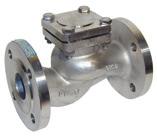
Mounting and Operating Manual Non-Return valves Swing-Check valves
 Mounting and Operating Manual Non-Return valves Swing-Check valves END-Armaturen GmbH & Co. KG Oberbecksener Str. 78 D-32547 Bad Oeynhausen Telefon (05731) 7900-0 Telefax (05731) 7900-199 http://www.end.de
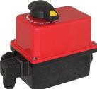
Original Operating Manual Pneumatic Actuator ED /EE
 Original Operating Manual Pneumatic Actuator ED /EE acc. to annex VI of the Directive 2006/42/EC END-Armaturen GmbH & Co. KG Oberbecksener Str. 78 D-32547 Bad Oeynhausen Telefon (05731) 7900-0 Telefax
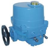
Original Operating Manual Motor Control Valve MBA / MBK NBA / NBK EBA / EBK
 Original Operating Manual Motor Control Valve MBA / MBK NBA / NBK EBA / EBK acc. to annex VI of the Directive 2006/42/EC END-Automation GmbH & Co. KG Postfach (PLZ 32503) 100 342 Oberbecksener Str. 78
watergates knife-gate-valves - Stoffschieber
 watergates knife-gate-valves - Stoffschieber Original Operating Manual Knife-gate valves acc. to annex VI of the Directive 2006/42/EC [Contact] Watergates GmbH & Co. KG Postfach (PLZ 32503) 101 321 Oberbecksener
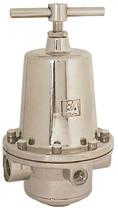
Original Operating Manual Pressure Actuated Valve
 Original Operating Manual Pressure Actuated Valve DG2D1 DG2D2 DG2D3, DA2D3, DL2D3, DM2D3, DG3D3, DF3D acc. to annex VI of the Directive 2006/42/EC END-Armaturen GmbH & Co. KG Postfach (PLZ 32503) 100 341
Combined operated solenoid valves.../ax..
 0032 Combined operated solenoid valves.../ax.. (version acc. to European Directive 2014/34/EU(ATEX)) Mounting and Operating Manuel for explosion proofed solenoids END-Automation GmbH & Co. KG D-32547 Bad
Operating Instructions for Magnetic Filter. Model: MFR-00
 Operating Instructions for Magnetic Filter Model: MFR-00 1. Contents 1. Contents... 2 2. Note... 3 3. Instrument Inspection... 3 4. Regulation Use... 3 5. Operating Principle... 4 6. Mechanical Connection...
Servo assisted solenoid valves.../ax..
 Servo assisted solenoid valves.../ax.. (version acc. to European Directive 2014/34/EU(ATEX)) Mounting and Operating Manuel for explosion proofed solenoids END-Armaturen GmbH & Co. KG Postfach (PLZ 32503)
Content Copyright...1 Disclaimer...2 General advice...3 Safety Instructions...4 References Of Legal Regulations For Operation...4 Hints...5 Scope Of D
 Version 1.01 (10.10.2013) Installation Instructions DAB / DAB+ Antenna module Articlenr. 39336 VW Sharan 7N www.kufatec.de Kufatec GmbH & Co. KG Dahlienstr. 15 23795 Bad Segeberg e-mail: info@kufatec.de
Storage, operating and maintenance instructions for AZ plug valves and Standard valves
 ARMATUREN Plug - Valves metallic with PTFE Sleeve 2-7 way Storage, operating and maintenance instructions for AZ plug valves and Standard valves Plug - Valves FEP/PFA - lined, 2-3 way Butterfly - Valves
Content Copyright...1 Disclaimer...2 General Advice...3 Safety Instructions...4 Reference Of Legal Regulations For Operation...4 Hints...5 Scope Of De
 Version 1.01 (11.10.2013) Installation Instructions DAB / DAB+ Antenna module Articlenr. 39338 VW Golf 6 www.kufatec.de Kufatec GmbH & Co. KG Dahlienstr. 15 23795 Bad Segeberg e-mail: info@kufatec.de Content
back to main page Type: Butterfly valves Instructions and Operation Manual Warning! Warning! Danger for life! 1. Intended use Danger for life!
 Instructions and operation manual for butterfly valves This manual is intended to support the users of Herberholz butterfly valves type HRD/HRA, RD/RA, LDKE/LDKF for installation, operation and maintenance
Declaration of Conformity as per Directive 97/23/EC
 Declaration of Conformity as per Directive 97/23/EC The manufacturer declares that:, 47906 Kempen, Germany PTFE-lined Rotary plug valves Series 23e, with packing with lever for 90 operation with worm gear
Series 250 Pneumatic Control Valves Type and
 Series 250 Pneumatic Control Valves Type 3252-1 and 3252-7 Fig. 1 Type 3252 High-pressure Valve with Type 3277 Pneumatic Actuator and Type 3767 i/p Positioner Edition November 1998 Mounting and operating
These installation and maintenance instructions must be read in full and completely understood before the installation!
 These installation and maintenance instructions must be read in full and completely understood before the installation! 1. General information on the installation and maintenance instructions These instructions
Operating and installation instructions
 Strainer PN6-160 1.0 General information on operating instructions...2-2 2.0 Notes on possible dangers...2-2 2.1 Significance of symbols... 2-2 2.2 Explanatory notes on safety information... 2-2 3.0 Storage
Pressure Reducing Valve Type 2114/2415
 Pressure Reducing Valve Type 2114/2415 Fig. 1 Type 2114/2415 1. Design and principle of operation The Type 2114/2415 Pressure Reducing Valve consists of the Type 2114 Valve and the Type 2415 Actuator.
Mounting and Operating Instructions EB 8222 EN. Type 3310/AT and Type 3310/3278 Pneumatic Control Valves. Type 3310 Segmented Ball Valve
 Type 3310/AT and Type 3310/3278 Pneumatic Control Valves Type 3310 Segmented Ball Valve Fig. 1 Type 3310/3278 with positioner Fig. 2 Type 3310/AT Mounting and Operating Instructions EB 8222 EN Edition
Type Operating Instructions. Bedienungsanleitung Manuel d utilisation. 2/2-Way Solenoid Valve 2/2-Wege-Magnetventil Électrovanne à 2/2 voies
 Type 5282 2/2-Way Solenoid Valve 2/2-Wege-Magnetventil Électrovanne à 2/2 voies Operating Instructions Bedienungsanleitung Manuel d utilisation 1 OPERATING INSTRUCTIONS The operating instructions contain
Operating Instructions Garlock Butterfly Valves DN : mm / 2-24
 Operating Instructions Garlock Butterfly Valves DN : 50-600 mm / 2-24 PN : 10 / 16 Type: GAR-SEAL SAFETY-SEAL STERILE-SEAL MOBILE-SEAL Conformity declaration... 14 0 Introduction... 15 1 Proper use...
NEOTECHA NTB-NTC BALL VALVES INSTALLATION AND MAINTENANCE INSTRUCTIONS
 Before installation these instructions must be fully read and understood 2 SAFETY Please also read through these notes carefully. 2.1 General potential danger due to: a. Failure to observe the instructions
Pressure relief valve
 Pressure relief valve Operating manual Series DHV 712 Version BA-2015.10.20 EN Print-No. 300 510 TR MA DE Rev001 ASV Stübbe GmbH & Co. KG Hollwieser Straße 5 32602 Vlotho Germany Phone: +49 (0) 5733-799-0
Safety. Operating instructions Solenoid valve VGP DANGER. Contents WARNING CAUTION. Changes to edition Elster GmbH Edition 10.
 27 Elster GmbH Edition.7 Translation from the German 344297 D F NL I E DK S N P GR TR CZ PL RUS H www.docuthek.com Operating instructions Solenoid valve Contents Solenoid valve... Contents... Safety....
Operating and Maintenance Manual. for. HADEF overhead crane. as jointed crane TA
 5.52.714.00.1.0 Edition 03.2004 GB Operating and Maintenance Manual for HADEF overhead crane as jointed crane TA Subject to changes. 1 HADEF Table of Contents 1 General Page 3 2 Product description Page
Type Operating Instructions. Bedienungsanleitung Manuel d utilisation. 2/2-way solenoid valve 2/2-Wege-Magnetventil Électrovanne 2/2 voies
 Type 5404 2/2-way solenoid valve 2/2-Wege-Magnetventil Électrovanne 2/2 voies Operating Instructions Bedienungsanleitung Manuel d utilisation Contents 1 Operating instructions...2 2 Intended use...3 3
Installation, Operation, and Maintenance Manual
 Industrial Process Installation, Operation, and Maintenance Manual Series PBV Plastic Lined Ball Valve Table of Contents Table of Contents Introduction and Safety...2 Safety message levels...2 User health
Angle seat valve with diaphragm actuator VZXA-...-M
 Angle seat valve with diaphragm actuator VZXA-...-M Instructions Operating (Translation of the original instructions) Festo AG & Co. KG Ruiter Straße 82 73734 Esslingen Germany +49 711 347-0 www.festo.com
Operating Instructions
 Armaturen GmbH Armaturen, Rohre, Sonderteile aus Edelstahl fittings, pipes, special parts of stainless steel Operating Instructions BaseCom butterfly valve Rev.0 / 12.12.2009 Page 1 of 8 BA52290GB.doc
Mounting and Operating Instructions EB 8111/8112 EN. Valve Series V2001 Globe Valve Type 3321
 Valve Series V2001 Globe Valve Type 3321 Fig. 1 Type 3321 Valve with mounted rod-type yoke for pneumatic or electric actuators (partial view) Mounting and Operating Instructions EB 8111/8112 EN Edition
Operating Instructions K Always on the safe side.
 Operating Instructions K9 4953. Always on the safe side. KaVo Dental GmbH Wangener Straße 78 D-88299 Leutkirch Tel.: 0 75 61 / 86-150 Fax: 0 75 61 / 86-265 A 1 User information...2 A 1.1 Meaning of the
T R A N S L A T I O N Declaration of Conformity as per Directive 2014/68/EU
 T R A N S L A T I O N Declaration of Conformity as per Directive 2014/68/EU The manufacturer declares that: Pfeiffer Chemie-Armaturenbau GmbH, 47906 Kempen, Germany Butterfly valves BR14a, BR14b, BR14b-Type
Installation and Operating Manual for Tank and Equipment Cleaning Nozzles Series 5TM
 Installation and Operating Manual for Tank and Equipment Cleaning Nozzles Series 5TM 150 150 150 This instruction manual contains proprietary information which is protected by copyright laws. No part of
AC 100. Operating instructions Pneumatic Crimper AC 100. Date of issue: 05/2010. Keep for future use!
 Operating instructions Pneumatic Crimper AC 100 Date of issue: 05/2010 Keep for future use! SAFETY SAFETY Basic information The basic prerequisite for ensuring safe use and continuous operation of the
Valve Series V2001 Three-way Valve Type 3323
 Valve Series V2001 Three-way Valve Type 3323 Fig. 1 Type 3323 Valve with mounted rod-type yoke (partial view) Edition January 1999 Mounting and operating instructions E 8113/8114 EN 1. Design and principle
Mounting and Operating Instructions EB 8091 EN. Pneumatic Control Valve Type and Type Type with 120 cm 2 actuator
 Pneumatic Control Valve Type 3510-1 and Type 3510-7 Type 3510-1 with 120 cm 2 actuator Type 3510-7 with 120 cm 2 actuator and integrated positioner Type 3510-1 with 60 cm 2 actuator Fig. 1 Pneumatic control
Operating Instructions: Hand-operated, PTFE-lined butterfly valves, Series 22/23
 0 Introduction These instructions are intended to assist users of BRAY PTFE-lined butterfly valves, Series 22/23 in fitting, operating and servicing valves. Risks may arise and the manufacturer's warranty
Type 5411, Operating Instructions. Bedienungsanleitung Manuel d utilisation
 Type 5411, 5413 3/2 or 4/2 way solenoid valve 3/2 oder 4/2-Wege-Magnetventil Électrovanne 3/2 ou 4/2 voies Operating Instructions Bedienungsanleitung Manuel d utilisation 1 THE OPERATING INSTRUCTIONS The
Type Operating Instructions. Bedienungsanleitung Manuel d utilisation. 2/2-Way Solenoid Valve 2/2-Wege-Magnetventil Électrovanne à 2/2 voies
 Type 5282 2/2-Way Solenoid Valve 2/2-Wege-Magnetventil Électrovanne à 2/2 voies Operating Instructions Bedienungsanleitung Manuel d utilisation Contents 1 Operating Instructions... 2 2 Authorized use...
Installation Instructions RFK VW Amarok
 Version 1.04 (09.06.2015) Installation Instructions RFK VW Amarok Articlenr. 38352 VW Amarok www.kufatec.de Kufatec GmbH & Co. KG Dahlienstr. 15 23795 Bad Segeberg e-mail: info@kufatec.de Content Copyright...
Angle seat valve with piston actuator VZXA-...-K
 Angle seat valve with piston actuator VZXA-...-K Festo AG & Co. KG Postfach 73726 Esslingen Germany +49 711 347-0 www.festo.com 3 Further information Accessories www.festo.com/catalogue Spare parts www.festo.com/spareparts
VARICOOL - V901. Injection Nozzle Valve Fig. 1
 VARICOOL - V901 Injection Nozzle Valve Fig. 1-1 - List of contents 1 1.1 1.2 1.3 1.4 1.5 1.6 1.7 2 3 4 5 6 6.1 6.2 6.3 6.4 6.5 6.6 6.7 7 Operating instructions Installation Delivery status Installation
Angle seat valve with piston actuator VZXA-...-K
 Angle seat valve with piston actuator VZXA-...-K Instructions Operating (Translation of the original instructions) Festo AG & Co. KG Ruiter Straße 82 73734 Esslingen Germany +49 711 347-0 www.festo.com
Operating Instruction:
 Operating Instruction: Leakage - Butterfly valve with manual operation Types LSV 4365 LSV 4366 LSV 4367 LSV 4368 LSV 4369 LSV 4370 Kieselmann GmbH Paul-Kieselmann-Str. 4-10 75438 Knittlingen Telefon +49
Type Operating Instructions. Bedienungsanleitung Manuel d utilisation. 2/2-way solenoid valve 2/2-Wege-Magnetventil Électrovanne 2/2 voies
 Type 6027 2/2-way solenoid valve 2/2-Wege-Magnetventil Électrovanne 2/2 voies Operating Instructions Bedienungsanleitung Manuel d utilisation 1 OPERATING INSTRUCTIONS The operating instructions contain
Mounting and operating instructions EB 8093 EN. Series 240 Pneumatic Control Valve for Cryogenic Temperatures. Type and
 Series 240 Pneumatic Control Valve for Cryogenic Temperatures Type 3248-1 and 3248-7 Fig. 1 Type 3248 Cryogenic Valve with Type 3277 Pneumatic Actuator as globe and angle valve Mounting and operating instructions
Type Operating Instructions. Bedienungsanleitung Manuel d utilisation
 Globe control valve, pneumatically operated Actuator sizes 40 mm - 125 mm, Nominal diameter DN10-65 Kolbengesteuertes Geradsitzventil Antriebsgrößen 40 mm - 125 mm, Nennweiten DN10-65 Vanne à siège droit
Serie 2003/2013. Three-way Control Valve, mixing/diverting. Wörth am Main. Service. Control Valve Division
 Serie 2003/2013 Three-way Control Valve, mixing/diverting Service Preventive maintenance Preventive maintenance primarily consists of making a regular visual inspection of the valve assembly. This can
original operating manual Operating manual Translation of the Item-No.: ,
 Translation of the original operating manual Operating manual Item-No.: 015 431 551, 015 431 581 Important! Copyright The operating manual is always to be read before commissioning the equipment. No warranty
Operating and Installation Instructions Pulsation Damper P Series for Pumps of the BIOCOR Series
 Operating and Installation Instructions Pulsation Damper P Series for Pumps of the BIOCOR Series ought to be studied before installing the pulsation damper Original Instruction Introduction ALMATEC pulsation
User Guide. Lubricus Lubrication System LUB-D1/LUB-D2/LUB-D3/LUB-D4 (24 VDC)
") User Guide Lubricus Lubrication System LUB-D1/LUB-D2/LUB-D3/LUB-D4 (24 VDC) version 04/2013 Content General Information 3 Warning 3 Scope of Supply 3 Overview 3 General safety details 4 Intended use 4
User Guide Lubricus Lubrication System LUB-D1/LUB-D2/LUB-D3/LUB-D4 (24 VDC) version 04/2013 Content General Information 3 Warning 3 Scope of Supply 3 Overview 3 General safety details 4 Intended use 4
Mounting and Operating Instructions EB 8097 EN. Pneumatic Control Valves Type and Type
 Pneumatic Control Valves Type 3347-1 and Type 3347-7 Hollow-mold cast body with welding ends Full-mold cast body with threaded connections Fig. 1 Type 3347-7 Control Valve with Type 3277 Actuator and integral
Installation instruction Sound Booster Pro Active Sound
 Version 1.03 (20.04.2016) Installation instruction Sound Booster Pro Active Sound Article no. 40180 Audi A6 4G Audi A7 4G Audi Q5 8R www.kufatec.de Kufatec GmbH & Co. KG Dahlienstr. 15 23795 Bad Segeberg
EN Operating manual. Motorised zone valve. Three-way, 22 mm & 28 mm 3PV2, 3PV8 & VRMH3
 EN Operating manual Motorised zone valve Three-way, 22 mm & 28 mm 3PV2, 3PV8 & VRMH3 This manual ensures safe and efficient use of the 3PV2 or 3PV8 force-actuated three-way valve with spring-loaded return
Mini UHV gate valve with manual actuator with pneumatic actuator
 Mini UHV gate valve with manual actuator with pneumatic actuator This manual is valid for the valve ordering numbers: 004/8/3/34-. E0/08 004/8/3/34-. E//3/4 004/8/3/34-. E//3/4 004/8/3/34-. E4/4/34/44
Operating Instructions Ball Valves
 Armaturen GmbH Armaturen, Rohre, Sonderteile aus Edelstahl Fittings, pipes, special parts of stainless steel Operating Instructions KV-SS KV-ZF M & S Armaturen GmbH Carl Benz Str.2 D-75057 Kürnbach Germany
Globe Valve Type Fig. 1 Type 3241 Globe Valve. Mounting and Operating Instructions EB EN
 Globe Valve Type 3241 Fig. 1 Type 3241 Globe Valve Mounting and Operating Instructions EB 8015-1 EN Edition July 2012 Contents Contents Page 1 Design and principle of operation.................... 4 2
Installation manual Complete set active Sound incl. Soundbooster Skoda Octavia 5E
 Version 1.04 (01.06.2017) Installation manual Complete set active Sound incl. Soundbooster Skoda Octavia 5E Articel no. 40590 www.kufatec.de Kufatec GmbH & Co. KG Dahlienstr. 15 23795 Bad Segeberg e-mail:
Pneumatic Control Valve Assembly Type 3331/3278
 Pneumatic Control Valve Assembly Type 3331/3278 Fig. 1 Type 3331/3278 Pneumatic Control Valve Assembly 1. Design and principle of operation The pneumatic control valve assembly consists of a Type 3331
Type 3320, Service Manual. Serviceanleitung Service Manuel
 Electromotive 2/2-way valve Elektromotorisches 2/2-Wege-Ventil Vanne électromotorisée à 2/2 voies Service Manual Serviceanleitung Service Manuel We reserve the right to make technical changes without notice.
Mounting and Operating Instructions EB 8227 EN. Pneumatic Control Valve Type 3331/BR 31a Special version Type 3331/3278. Type 3331 Butterfly Valve
 Pneumatic Control Valve Type 3331/BR 31a Special version Type 3331/3278 Type 3331 Butterfly Valve Fig. 1 Type 3331/BR 31a (below) and Type 3331/3278 (top) Mounting and Operating Instructions EB 8227 EN
Operating and installation instructions
 Pneumatic actuators DP34 Tandem / DP34 Tridem DP34T Contents DP34Tri 1.0 General information on operating instructions...2-2 2.0 Notes on possible dangers...2-2 2.1 Significance of symbols...2-2 2.2 Explanatory
Mounting and Operating Instructions EB 8053 EN. Series 250 Type and Type Pneumatic Control Valves
 Series 250 Type 3252 1 and Type 3252 7 Pneumatic Control Valves Type 3252 High-pressure valve with Type 3277 Pneumatic Actuator and Type 3767 Electropneumatic Positioner Mounting and Operating Instructions
Mounting and Operating Instructions EB 8097 EN. Type and Type Pneumatic Control Valves
 Type 3347-1 and Type 3347-7 Pneumatic Control Valves Type 3347-7, cast body with welding ends Type 3347-7, bar stock body with threaded connections Mounting and Operating Instructions EB 8097 EN Edition
Exchange of rollers from the XTS-Mover
 Service documentation for AT901-0050-0550 and AT9011-00x0-0550 Version: Date: 1.0 0.10.017 Table of contents Table of contents 1 Foreword... 5 1.1 Notes on the documentation... 5 1. Documentation issue
Type 6213 EV, 6281 EV
 Type 6213 EV, 6281 EV 2/2-way solenoid valve 2/2-Wege-Magnetventil Électrovanne 2/2 voies Operating Instructions Bedienungsanleitung Manuel d utilisation 1 OPERATING INSTRUCTIONS The operating instructions
D58 Series Brake Instructions
 D58 Series Brake Instructions 4740 W. Electric Avenue Milwaukee, WI 53219 414/672-7830 FAX 414/672-5354 www. dingsbrakes.com Safety information 2 Safety information 2.1 Persons responsible for the safety
DSV. Operating Manual. Double Seal Butterfly Valve. Read and understand this manual prior to operating or servicing this product.
 Operating Manual DSV Double Seal Butterfly Valve Read and understand this manual prior to operating or servicing this product. www.sks-online.com UK DSV-UK2.qxp / 10.2005 Table of Contents: Page: 1.
Compact System NRGS 11-2 NRGS Original Installation Instructions English
 Compact System NRGS 11-2 NRGS 16-2 EN English Original Installation Instructions 810366-05 1 Contents Important Notes Page Usage for the intended purpose...4 Safety note...4 LV (Low Voltage) Directive
Mounting and Operating Instructions EB 8048 EN. Type and Type Pneumatic Control Valves Type 3249 Aseptic Angle Valve
 Type 3249-1 and Type 3249-7 Pneumatic Control Valves Type 3249 Aseptic Angle Valve Ball body version Special version with packing Type 3249-7 Control Valve with Type 3277 Actuator and integrated positioner
Operating and installation instructions
 Series 470 Series 471 Contents 1.0 General information on operating instructions...2-2 2.0 Notes on possible dangers...2-2 2.1 Significance of symbols... 2-2 2.2 Explanatory notes on safety information...
Operating Instruction
 Armaturen GmbH Armaturen, Rohre, Sonderteile aus Edelstahl fittings, pipes, special parts of stainless steel Operating Instruction Leakage butterfly valve manually operated with handle LSV07 manually operated
Mounting and Operating Instructions EB 8039 EN. Type 3351 Pneumatic On/off Valve. Type 3351 Pneumatic On/off Valve. Type 3351 Pneumatic On/off Valve
 Type 3351 Pneumatic On/off Valve Type 3351 Pneumatic On/off Valve Type 3351 Pneumatic On/off Valve Version with handwheel Mounting and Operating Instructions EB 8039 EN Edition May 2016 Definition of signal
Operating and installation instructions
 DP30 DP32 DP33 DP34 Contents 1.0 General information on operating instructions... 2-2 2.0 Notes on possible dangers... 2-2 2.1 Significance of symbols... 2-2 2.2 Explanatory notes on safety information...
USERS MA UAL Bellow sealed valve Fig.229, 230, 234, 235 Edition: 1/2008
 诲眾 ᓠ 睂睄 睄 ɞ 1/7 ZETKAMA Spółka Akcyjna ul. 3 Maja 12 PL 57-410 Ścinawka Średnia USERS MA UAL Bellow sealed valve Fig.229, 230, 234, 235 Edition: 1/2008 Date: 01.01.2008 CONTENTS 1. Product description
VAG CEREX M300 Butterfly Valve
 Operation and Maintenance Instructions VAG CEREX M300 Butterfly Valve KAT 1310-B Edition4 12-17 Table of Contents 1 General 3 1.1 Safety 3 1.2 Proper use 3 1.3 Identification 3 VAG reserves the right to
Mounting and Operating Instructions EB 8135/8136 EN. Series V2001 Valves Type 3535 Three-way Valve for Heat Transfer Oil
 Series V2001 Valves Type 3535 Three-way Valve for Heat Transfer Oil Type 3535 Three-way Valve with bellows seal and rod-type yoke (partial view) Mounting and Operating Instructions EB 8135/8136 EN Edition
Maintenance instruction
 Maintenance instruction This maintenance instruction is a step-by-step instruction for service and maintenance on Stafsjö s HG valve. Same procedure also applies for HL, HP and HPT. The instruction shall
Type 0283, Operating Instructions. Bedienungsanleitung Manuel d utilisation. 2/2-way solenoid valve 2/2-Wege-Magnetventil Électrovanne 2/2 voies
 Type 0283, 0293 2/2-way solenoid valve 2/2-Wege-Magnetventil Électrovanne 2/2 voies Operating Instructions Bedienungsanleitung Manuel d utilisation Contents 1 The operating instructions...2 2 Intended
Safety. Operating instructions Solenoid valve for gas VG 6 VG 15/10 DANGER. Contents WARNING CAUTION. Changes to edition 07.15
 17 Elster GmbH Edition 1.17 Translation from the German 519 D F NL I E DK S N P GR TR CZ PL RUS H www.docuthek.com Operating instructions Solenoid valve for gas VG VG 15/1 Contents Solenoid valve for gas
Installation, Operation, and Maintenance Manual
 Industrial Process Installation, Operation, and Maintenance Manual Cam-Tite Ball Valve Table of Contents Table of Contents Introduction and Safety...2 Safety message levels...2 User health and safety...2
Installation, Operating & Maintenance Instructions. HV gate valve with pneumatic actuator. Series 110 DN mm (I. D.
 Installation, Operating & Maintenance Instructions HV gate valve with pneumatic actuator Series 110 DN 250 320 mm (I. D. 10" 12") This manual is valid for the following product ordering numbers: 11048-.
T R A N S L A T I O N Declaration of Conformity as per Directive 2014/68/EU
 T R A N S L A T I O N Declaration of Conformity as per Directive 2014/68/EU The manufacturer declares that: Pfeiffer Chemie-Armaturenbau GmbH, 47906 Kempen, Germany PFA/PTFE-lined ball valves BR20a, BR20b,
INSTRUCTION MANUAL. I/P Converter DSG BXXY3Z DSG BXXY4Z
 INSTRUCTION MANUAL I/P Converter DSG BXXY3Z DSG BXXY4Z Revision 2.0 3.626 016136 en Page 1/15 Should you have any questions concerning the I/P converter, please contact the Service Department of the Product
Manufacturer s Declaration as per EU-Directives Page 1 of 2
 The manufacturer Manufacturer s Declaration as per EU-Directives Page 1 of 2 BRAY Armaturen & Antriebe Europa, D47807 Krefeld for Butterfly valves all Series 2[.].& Series 3[.] : Series 20/21 (2 body-halves
Type 2000, 2002, 2012
 Replacement of valve and seal set Conversion of control function Service Manual We reserve the right to make technical changes without notice. Technische Änderungen vorbehalten. Sous réserve de modifications
Pneumatic Controller for Temperature. Type Pneumatic Controller for Temperature. Type Mounting and Operating Instructions EB 7065 EN
 Pneumatic Controller for Temperature Type 3301 Pneumatic Controller for Temperature Type 301-1 Mounting and Operating Instructions EB 7065 EN Edition January 2014 Definition of the signal words used in
VARIFUEL MAINTENANCE AND REPAIR INSTRUCTIONS
 VARIFUEL2 140-65 MAINTENANCE AND REPAIR INSTRUCTIONS MOTORTECH Gas Regulation P/N 01.50.008-140-65-EN Rev. 06/2015 Copyright Copyright 2015 MOTORTECH GmbH. All rights reserved. Distribution and reproduction
Turbocharger / A100-L Original assembly instructions English
 Assembly Instructions Turbocharger / A100-L Original assembly instructions English This document is valid for the A100-L series: A165-L, A170-L, A175-L, A180-L, A185-L, A190-L Purpose The assembly instructions
Operating and installation instructions
 Check valves Contents 1.0 General information on operating instructions...2-2 2.0 Notes on possible dangers...2-2 2.1 Significance of symbols... 2-2 2.2 Explanatory notes on safety information... 2-2 3.0
Product Information Overspeed governor GB 260
 Product Information GB 260 Copyright as per DIN ISO 16016. Manufactured under licence of C. Haushahn GmbH & Co. I Subject to modification. Published by SLC Sautter Lift Components GmbH & Co. KG Borsigstrasse
Operating manual Separator
 Operating manual Separator Sheet no. AS/4.1.141.1.1 issue 20.08.2014 Contents Section Title Page 0 Introduction... 1 1 Intended use......1 2 Marking of the fitting... 1 3 Safety instructions... 2 4 Transport
Installation manual wall-mounted distributor
 EN Installation manual wall-mounted distributor EN 60003233 Issue 11.2016 2016-14-11 Table of contents 1 About this manual 3 1.1 Structure of the warnings 3 1.2 Symbols used 4 1.3 Signal words used 4 2
Operating & Maintenance Manual For Steam Conditioning Valve
 For Steam Conditioning Valve 1 Table of Contents 1.0 Introduction 3 2.0 Product description 3 3.0 Safety Instruction 4 4.0 Installation and Commissioning 5 5.0 Valve Disassembly 6 6.0 Maintenance 6 7.0
Bowl feeder WV401-1 / Translation of operating and installation instructions
 Bowl feeder WV401-1 / 402-1 Translation of operating and installation instructions Copyright by Afag GmbH This operation instruction applies to: Bowl feeder WV401-1 Bowl feeder WV402-1 Type 230 V / 50
Operating Instructions
 Operating Instructions Quadax Series Butterfly Valves (with actuator) Version September 2009 müller co-ax ag Gottfried-Müller-Str. 1 74670 Forchtenberg Germany Tel. +49 7947 828-0 Fax +49 7947 828-11 E-Mail
Installation, Operating & Maintenance Instructions. UHV gate valve with pneumatic actuator. Series 108 DN mm (I. D. 2½ 8 )
") Installation, Operating & Maintenance Instructions UHV gate valve with pneumatic actuator Series 108 DN 63 200 mm (I. D. 2½ 8 ) This manual is valid for the following product ordering numbers: 108.. -.
Installation, Operating & Maintenance Instructions UHV gate valve with pneumatic actuator Series 108 DN 63 200 mm (I. D. 2½ 8 ) This manual is valid for the following product ordering numbers: 108.. -.
VARIFUEL MAINTENANCE AND REPAIR INSTRUCTIONS
 VARIFUEL2 200-120 MAINTENANCE AND REPAIR INSTRUCTIONS MOTORTECH Gas Regulation P/N 01.50.008-200-120-EN Rev. 06/2015 Copyright Copyright 2015 MOTORTECH GmbH. All rights reserved. Distribution and reproduction
HST -LS Interlocking device (Translation of Original Manual)
") Installation and Operating Manual for Components HST -LS Interlocking device (Translation of Original Manual) HST-LS Ident.-No.: 10268 HST-LS Ident.-No.: 10269 HST-LS, pictured Ident-Nr. 10269 The image
Installation and Operating Manual for Components HST -LS Interlocking device (Translation of Original Manual) HST-LS Ident.-No.: 10268 HST-LS Ident.-No.: 10269 HST-LS, pictured Ident-Nr. 10269 The image
Globe Control Valve Series 1a
 Maintenance Globe Control Valve Series 1a are subject to alteration without notice. The text and illustrations do not necessarily display the scope of supply or any ordering of spare parts. Drawings and
MICHIGAN FLUID POWER
 MICHIGAN FLUID POWER Air Driven Hydraulic Pumps, Power Units and Intensifiers P901 Installation, Use and Maintenance Manual Contents Introduction, Guarantee and Identification Plate Description, Start