Technology you can count on. Instruction manual Version B 0702 English. No. : CHAMPION HEADERS
|
|
|
- Crystal Benson
- 6 years ago
- Views:
Transcription


 25 63 / 88-0 E-mail:")
1 Technology you can count on Instruction manual Version B 0702 English No. : CHAMPION HEADERS Maschinenfabrik KEMPER GmbH & Co. KG D Stadtlohn P.O. Box 1352 Tel.: +49 (0) / Info@Kemper-Stadtlohn.de Internet:
2

 25 63-88 26 / 88 32 / 88 84 Fax - National Sales Management +49 (0) 25 63-88 155 Sales, Machinery +49 (0) 25 63-88 98 Sales, Spare Parts +49 (0) 25 63-88 95 Customer Service +49 (0) 25 63-88 147")
3 Design and model claims The construction and function of our products are subject to technical continuous and further development, which means information and data pertaining to a delivery are not binding. Telephone-National Sales Management +49 (0) Sales, Machinery +49 (0) Shipping Status +49 (0) Sales, Spare Parts +49 (0) / Customer Service +49 (0) / / Fax - National Sales Management +49 (0) Sales, Machinery +49 (0) Sales, Spare Parts +49 (0) Customer Service +49 (0) Telephone - International Sales Management +49 (0) Sales Management +49 (0) Sales, Machinery +49 (0) / / Sales, Spare Parts +49 (0) / / Customer Service +49 (0) / / Fax - International Sales Management +49 (0) Sales, Machinery +49 (0) Sales, Spare Parts +49 (0) Customer Service +49 (0) Telephone National+ International Fax - National + International Product Information +49 (0) Product Information +49 (0) Maschinenfabrik KEMPER GmbH & Co. KG Postfach 1352 D Stadtlohn Tel. +49(0) 2563 / Info@Kemper-Stadtlohn.de web: www. Kemper-Stadtlohn.de
4 0611 Introduction 0611 Foreword Carefully read this operating manual to familiarise yourself with the correct operation and maintenance of the machine and to prevent injury and damage to the equipment. This operating manual and the safety labels attached to the machine are available in various languages (contact your KEMPER dealer for details). This operating manual is an integral part of the delivery. When the machine is sold, the manual must be handed over with the equipment to the new owner. All dimensions in this operating manual are in metric units. Use only fitting parts and screws. The directions of "RIGHT" and "LEFT" are indicated relative to the direction of forward travel of the machine. Enter the product identification codes in the respective section. Please copy all digits and check them to be sure that they are correct. In the event of theft of the machine, these codes might assist the police in their enquiries. These codes are also required by the KEMPER dealer for spare part orders. We recommend noting the codes also in another document. The machine has been thoroughly tested and inspected by your dealer prior to delivery. The attachment may only be used for its intended purpose and in line with standard agricultural work practices (see section "Proper use"). Any other use is deemed improper. The manufacturer shall not be liable for damage caused by improper use. Proper use includes compliance with the operating, maintenance and repair instructions and schedules laid down by the manufacturer. The attachment may only be operated, serviced and repaired by persons who are fully familiar with the device and have been instructed regarding possible risks. Always adhere to all relevant accident prevention regulations and other safety practices. Also observe the relevant occupational health and road traffic regulations. Modifications to the attachment are forbidden. The manufacturer shall not be liable for any damage resulting directly or indirectly from modifications made to the equipment.
5 0611 Introduction 0611 Inspection completed prior to delivery The following tests, inspections, settings and maintenance tasks have been completed prior to the delivery of the machine: 1. Attachment properly mounted 8. All adhesive labels are OK. 2. Visual inspection for damage caused during transportation. 3. Lubricant applied to all lubrication points. 4. Friction clutches released. 9. Customer instructed in the operation of the device, with special reference to risks and safety measures. 10. Operating manual handed over to customer. 5. Transmission checked for leakage. 6. All moving parts tested for smooth movement. 7. All hydraulic lines and connections tested for leakage - all lines and connections are tight. Date: Signature of dealer/kemper specialist:
6 0611 Introduction 0611
7 0611 Table of contents 0611 Page Safety instructions... 1 Permitted use Identification of safety instructions Hazard symbols Accident prevention regulations Mechanical safety Safety instructions for assembling and removing the harvesting implement Safety instructions for working on equipment containing fluids under high pressure Safety instructions for welding and for the heating of components EC declaration of conformity Transfer of ownership of the equipment Product liability Obligation to provide information General... 4 Description of the equipment Design of the harvesting implements with description of the most important components. 4.2 Dimensions and weights of the implements Maintenance and testing Tightening torques for metric bolts and screws 4.5 Transporting the equipment Travelling on public highways Requirements made of forage harvesters Assisted steering Individual type approval Page Clutches Starting-off clutch (800 Nm) Starting-off clutch (900 Nm), liquid-cooled Dismantling the clutches Maintenance and service work Star ratchet Blades Maintenance of the crop intake and cutting area Inspecting the crop guide track Scrapers Attachment frame Faults and their causes Operations Instructions Starting, Turning, Reversing Downed Maize, WPS Attaching and Detaching Attachment to Claas forage harvesters Attachment to New Holland and Case forage harvesters Attachment to Mengele forage harvesters Make a note of serial number Hydraulic system... 7 Valves Throttles PTO... 9 Description of interaction of the various elements Description of the drives/transmissions with inlet, drain and breather bores Oil grades and capacities of the various drives/transmissions Lubricating schedule for the basic machine All information, illustrations and specifications in this manual are based on the latest information available at the time of publication. The right is reserved to make changes at any time without notice.
8 Chapter 1 Chapter 1 Point 1.1/1.2 Safety instructions Point 1.1/1.2 1 Safety instructions 1.1 Working with the implement: The Kemper Champion harvesting implement with interface for self-propelled forage harvesters is suitable for row-independent harvesting of silage maize, whole crop silage, lucerne, oil seed rape, field beans, sorghum, sunflowers and other stalk-type crops. This machine may only be used for the purpose for which it is intended, in keeping with equipment safety regulations. Failure to do so will nullify all liability in the event of any resulting injury or damage. Use for the purpose for which it is intended also includes the observation of our operating and maintenance instructions and sole use of genuine Kemper replacement parts. The Champion may only be used, serviced and repaired by persons who are familiar with the operation of this equipment or who have been instructed regarding the hazards involved. (see UVV 1.1 1) Important: It is forbidden to work on the header (removal of blockages, service and repair work) while the harvester engine is still running. The Champion header has undergone CE testing and is marked accordingly. 1.2 Recognising warnings This sign draws your attention to the safety instructions mounted on the machine and contained in the safety instructions. You must observe all safety and general accident prevention instructions.


9 Chapter 1 Chapter 1 Point 1.3 Safety instructions Point Safety instructions: Read the safety instructions and warning signs mounted on the machine and contained in the operating instructions carefully. Make sure that all signs can be easily read. Replace any signs which cannot be clearly read. Before you start working with the machine, make sure you are familiar with the overall machine operation. Always ensure the machine is in good condition. Unauthorised modifications will impair the proper functioning of the machine. Switch off the engine and remove the ignition key before commencing all service and repair work. Do not climb on to the machine before the power system has cut out, the engine has stopped and the ignition key has been removed.


10 Chapter 1 Chapter 1 Point 1.3 Safety instructions Point 1.3 Do not enter the hazard area between the header and the machine. Never put your hands in the auger while it is still turning. Do not access the intake parts of the implement before the power system has cut out, the engine has stopped and the ignition key has been removed.


11 Chapter 1 Chapter 1 Point 1.3 Safety instructions Point 1.3 Do not touch any moving parts. Do not stand or walk beneath external cutting units when in raised position. Beware of pressurised fluids emitted from the system! Never place your hands in areas where there is a crush hazard while it is still possible for parts to move.

12 Chapter 1 Chapter 1 Point 1.4 Safety instructions Point Accident prevention regulations It is forbidden to stand or walk in the crop intake area. Do not feed crop into the harvester using your hands. Do not push crop further into the machine using your foot. Exercise great care when connecting the jointed shafts. The jointed shaft guard must be kept in good condition at all times and the protecting tube must be secured against rotating. Do not alter the number of fins on the protection on the jointed shafts. If necessary, attach counterweights in order to make the tractor easier to steer, but be sure to observe maximum permitted axle loads. Adhere to the stipulations made in the individual typeapproval or in the government inspection survey regulations. Headers should only be detached and removed when the equipment is standing on a level surface. Whenever performing any work on the harvester the PTO lever must be switched to the "off" position; the tractor engine should be switched off and the ignition key removed. Caution: The blade rotors are still rotating even after the intake drums have come to a standstill! Before investigating the equipment for foreign bodies: Switch off all drive units; switch off the engine, and allow all moving parts to come to a complete standstill. The equipment should be securely supported whenever any work is carried out underneath the machine. Ensure that all blades are fixed securely. The hydraulic system operates under high pressure. Any hoses or lines showing signs of porosity, brittleness or any other kind of damage, must be replaced immediately; otherwise they should be replaced every 6 years at the latest. Maximum permitted oil pressure is 190 bar. Before removing hydraulic lines you should ensure the system is completely free of pressure. In the event of injury caused by hydraulic oil being emitted from the system under pressure, you should contact a doctor immediately. Before carrying out any work on the header: "Wait until the blade rotors have come to a complete standstill"
13 Chapter 1 Chapter 1 Point 1.4/1.5/1.6 Safety instructions Point 1.4/1.5/1.6 When travelling on the public highway: Observe all stipulations made in the extended individual type-approval (document 'ABE') regarding statutory highway regulations. Attach the folding accident protection guard with covers to the header. Attach all additional side lamps and indicators. The additional dipped headlamps should be switched on when travelling during hours of darkness. The reflecting hazard warning plates on the accident protection guard must be in good condition. The header must be raised so that the front accident protection guard is approx. 300 mm above the road surface. Government inspection survey regulations regarding axle loads, permitted gross vehicle weights and rear-end weights must be observed. Moreover, the general specifications contained in the accident protection regulations for machinery, equipment, tools, technical equipment and vehicles issued by the agricultural professional associations, UVV 3.1 to 3.11 must be observed. A measurement of the noise level was carried out during the CE test: max. noise level reaching the driver's ears, in conformity with regulation 86/188/EWG; measured in accordance with ISO 5131 with the cab closed, using a John Deere harvester 6910 = 80.0 db (A). Only genuine Kemper replacement parts should be used. 1.5 Mechanical safety Do not place your hands or any other objects inside the equipment while during operation or while the harvester engine is still running. Before carrying out repair and maintenance work, the harvester engine must be switched off and the ignition key removed. Safety devices may only be removed in order to perform repair and maintenance work. The permitted gross loads, axle loads and tyre pressures must not be exceeded. The statutory regulations of the highway code must be observed when travelling on public highways. 1.6 Safety instructions for attaching and removing the header The header may only be removed on firm, level ground. When removing the header, ensure it is standing securely. You may only enter the space between the harvesting attachment and the machine when the engine is switched off and when you have ensured it is not possible for the machine to roll forwards or backwards.
14 Chapter 1 Chapter 1 Point 1.8 /1.9 Safety instructions Point 1.8/ Safety instructions when working on systems containing pressurised fluids 1.9 Safety guidelines when welding and working with flame High-pressure fluids emitted from the system can penetrate the skin and cause serious injury. You should therefore ensure the system is de-pressurised before removing any hydraulic lines. Replace all connections firmly before pressurising the system again. Hydraulic fluid emitted from a small opening may be scarcely visible; you should therefore exercise extreme caution when working on high-pressure systems where there are leaks. Your hands and body should be protected when looking for leakages. You should consult a doctor immediately in the event of an injury of this type occurring. If any fluid has penetrated and lodged beneath the skin, it must be removed as soon as possible otherwise serious infections may result. Hazard from electrical current Use only welding equipment with electrics which are in perfect condition Do not carry out welding where there is an increased electrical hazard (welder standing on a surface which will conduct electricity, welding in a constrained position, welding in confined spaces...) Hazard from optical and UV radiation Use a face screen with sight glasses appropriate to the welding procedure in question (welding goggles, hand or head guard with appropriate glasses). Protect your body by wearing clothing appropriate to the welding procedure. Hazard from build-up of gases When components are subjected to heat, layers of paint and deposits of contamination contained on the components may combust. This will result in the formation of noxious vapours. It is therefore essential that layers of paint and contamination are removed before heat is applied to the components in the area to be welded. (Quite apart from the hazard involved, contamination will cause faults in the weld bead.) Weld bead faults will also occur when welding is carried out where a draft is present (stream of protective gas is blown away), or when moisture is present (hydrogen entering the weld bead). Hazard from heat Remember that a large amount of heat is applied to the material when welding, making the parts extremely hot. Make sure no combustible material is located within your work area. Wait until all hot tools and equipment have cooled down before touching them.
15 Chapter 2 Chapter 2 Point 2.0/2.1/2.2 Product liability Point 2.0/2.1/ Declaration of EC conformity This product has been tested and marked in accordance with EU directive 98/37/EC (Communauté européenne / European Community). A 'Declaration of EC Conformity' is attached to the instruction and should be delivered to the end-customer together with the instruction. 2.1 Transfer of ownership of the equipment Important! If the customer himself transfers ownership of the equipment to another party at a later date, the instruction must also be included in the transfer. 2.2 Obligation to provide information about product liability Product liability obliges the manufacturer and dealer to deliver the instruction when equipment is sold and to instruct the customer in the use of the equipment, referring to relevant operating, safety and maintenance regulations. A multi-copy form (A,B,C), as shown below, is attached to every copy of the instruction. Written confirmation is required as proof of the fact that the equipment and the instruction manual have been properly delivered. To this end, Document A must be signed and returned to Kemper. Document B is retained by the dealer supplying the equipment, and Document C is retained by the customer. This also ensure your warranty rights.

16 Chapter 4 Chapter 4 Point 4 General Point 4 4 General Our patented cutting system enables you to approach the maize stems from any direction you choose: parallel to the rows, perpendicular to the rows, or at an angle. Every single maize stem is fed automatically into a gap in the cutting head. In open-cut mode, i.e. without return cut, the crop stem is cut along the entire working width by the fast-action blade 9. The slow-action intake drum 1 feeds the stem along the intake bars 110. A row of teeth 111 grasp the stem securely. The forward movement of the intake drum pushes the crop up against the carrier teeth 11, thus allowing the crop to be transported safely past the guides and scrapers 22 to the intake drum. Here, the stem is placed against the carrier teeth 51 and is thus cleanly and evenly gathered lengthways. It is then fed pre-pressed to the header's pre-compression and intake rollers. Closely spaced rows - High crop yields Maize cultivation methods have formed the subject of intensive debate in recent times; there has also been a shift towards increasing crop yields by placing the individual plants closer together. However, if this new cultivation method is to be adopted, it is essential that the existing seed drills be used, and harvest is only possible with a row-independent harvesting system. The new cultivation method does not allow us to work with double rows; instead, the previous row distance of 75 cm must be reduced to 30 cm. Maintaining the same cultivation density of 10 plants/m 2 produces a greater distance between the plants in the individual rows. The advantages of the new cultivation method: More space for each individual plant. Faster overgrowing between rows and hence earlier shading of soil. Less soil erosion. Improved utilisation of nitrogen in the soil. Increased yields by approx %. Improved quality.


17 Chapter 4 Chapter 4 Point 4.1 General Point Description of the header Harvesting implement with integrated interface for self-propelled forage harvesters. When fitted with the appropriate interface, the header is suitable for attachment to a variety of self-propelled forage harvesters. Power transmission is delivered by the SPFH drive line via oilimmersed transmission and safety clutches. Row-independent cutting system with fast-running rotors and freewheel mechanism. Cutting across the entire working width by closed saw-type rotor blades with replaceable segments. Even crop intake to the chopping unit via slow-running intake drums and clean gathering by two slanting intake drums. Two mechanically driven crop separators for heavily laid crops, heightadjustable crop lifters. Champion 330 Working width = 3.0 m Champion 345 Working width = 4.5 m Champion 360 Working width =6.0 m Champion 375 Working width = 7.5 m


18 Chapter 4 Chapter 4 Point 4.2 General Point Design of the harvesting attachments with the major sub-assemblies Fig.9
19 Chapter 4 Chapter 4 Point 4.2 General Point 4.2 Sub-assembly designations 1 Rotating lodged maize auger 2 Outer feed bar 3 Transverse drum 4 Intake drum 5 Central feed bar 7 Centre guide 8 Elastic joint connection 9 Rear guard 10 Outer crop separator 11 Intake drum, left or right-rotating 12 Small crop separators 13 Shield 14 Central covering plate 15 Assisted steering 16 Large crop separators 17 Shield 18 Spur gear drives - Intake drum 19 Spur gear angle drive left and right 20 Knickgelenk?? 21 Spur gear angle drive - Transverse feed drum 22 Basic frame 23 Spur gear angle drive - Intake drum, left-rotating. 24 Breather - always outside! 25 Spur gear angle drive - Intake drum, right-rotating. 26 Starting-off clutch, right 27 Star ratchet M = Nm 28 Starting-off clutch - Friction clutch, left, 700 Nm Starting-off clutch - Friction clutch, left, 800 Nm Starting-off clutch - Friction clutch, water-cooled Left 900 Nm 29 Main drive shaft Compression spring in hinges 31 Hex shaft, outer 32 Freewheel, left or right 33 Cutting rotor 34 Blades 35 Coupling in hinges 36 Hex shaft, inner 37 Coupling shaft in main drive 38 Star ratchet M = Nm 39 Star ratchet M = 1800 Nm 40 Hydro-cylinder with dual check valve 41 Lateral tilt
20 Chapter 4 Chapter 4 Point 4.3 General Point Header dimensions and weights Harvester attachment type Unit of dimensio n Length m Overall width m Height m Working width m Transport width m Weight of basic version Kg Height folded in - lowered m Maintenance and testing Maintenance at start of new season The most important job to be performed before operating the header is to inspect the two friction clutches in the main power unit: remove both clutches, dismantle, clean or replace. (See appropriate instructions in the instruction manual) Before commencing new operation, we recommend star ratchets K 43 in the intake drums be inspected. For lubrication of the star ratchet (1 x year) we recommend a lithium saponified grease, "GLEITMO 805 and 810" made by Gleitmolybdän. This is particularly suitable for combating frictional corrosion. Run the machine and check all bearings for overheating or excess play. Daily maintenance Make sure scrapers (2 per rotor) beneath the rotor blade are intact. This is important as blunt or deformed scrapers can cause blockages and place an unnecessary strain on the power unit and friction clutches. Tighten the bolts after a few days' use when applying from new or when replacing the blades or scrapers. Check all rotor blades. Heavily worn blades should be replaced as they will create long stubble and place unnecessary strain on the power unit. The entire area surrounding the intake drums, rotor blades and scraper must be cleaned of husks and stem remains every day. Carry out a visual check of all transmissions every day to see if there are any oil leaks. Carrying out lubrication daily in accordance with the lubrication schedule merely means greasing the two front bearings on the side lodged maize augers, or, on certain models, greasing the jointed shaft. Weekly maintenance All bolts and screws should be checked at regular intervals to ensure they are firmly secured. Foreign bodies in the cutting area can cause damage to or deformation of the rotors, the carrier elements on the intake drums or the crop separators. You should therefore check the entire area. Clean the couplings in the Knickgelenk??.
21 Chapter 4 Chapter 4 Point 4.3 General Point Torques for metric bolts TORQUES FOR METRIC BOLTS in NM Size Lubricated * Grade 4.8 Grade 8.8 or 9.8 Grade 10.9 Grade 12.9 Dry* Lubricated* Dry* Lubricated* Dry* Lubricated * Dry* Nm Nm Nm Nm Nm Nm Nm Nm M M M M M M M M M M M M M M * Lubricated means that the bolts are supplied with a lubricant such as engine oil, or that phosphated or oiled bolts are used. "Dry means that normal or galvanised bolts without any lubrication are used. The torques specified in the table are guidelines only and do NOT apply where a different torque specification is given in this manual for certain bolts and nuts. Check that bolts and nuts are securely tightened. Shearing bolts are designed to shear off when a specific load is applied. Same grade bolts only should be used when replacing shearing bolts. When replacing bolts and nuts, ensure that same grade parts or better are used. Bolts and nuts of a higher grade should be tightened to the same torque as the parts originally used. Make sure that the threads engage properly and the bolts are correctly applied. This will prevent damage occurring when tightening. Tighten locknuts (not the bolts) with a plastic insert and flanged steel locknuts to approx. 50% of the 'dry' value given in the above table. Tighten hinge / nuts to the full torque value.
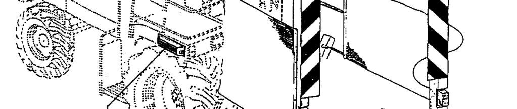
22 Chapter 4 Chapter 4 Point 4.6 General Point Transporting the equipment Fold in the outer cutting units for transport (transport width 3.00 m) Attach the folding accident prevention guard. (The transport guard is fitted with flashing lights and position lights.) When folded, the cutting units may partially cover the headlamps on some self-propelled forage harvesters. In this case, it may be necessary to re-position the headlamps to conform to the prevailing highway regulations, or to fit additional headlamps. When loading the equipment with the outer units folded, chains (or rope) must be used as shown in Fig.7. This will prevent the machine from toppling over. When loading in this way, you must exercise great care and use additional securing chains if necessary. 7 Fig.
23 Chapter 4 Chapter 4 Point 4.7 General Point Travelling on the public highway Steering To ensure proper steering is maintained, the steering axle on the transport vehicle must be equipped with counterweights, paying due attention to the permitted axle loads. Counterweight specifications are given in the appropriate government inspection survey regulations. Accident prevention When travelling on public highways the entire area around the crop separators must be covered with a folding guard. Assembly sequence: A After the rotors have come to a complete standstill, fold up the side cutting units. B Place the folding guard in a central position and insert the rubber rings. C Fold up the protective profiles on the side and insert rubber D rings. The runners, blades and other edges are covered with protective cloths. Ground clearance When travelling on public highways the harvesting attachment must be raised so that the front accident prevention device is approx. 300 mm above the road surface. Side lamps and indicators As the side lamps and indicators on the transport vehicle are usually covered by the intake drums in raised position, we have mounted duplicates of these inside the accident protection device. For the 12 V power supply a 7-pole plug is located on the right side of the harvester. Dipped headlamps Fig. 46 Fig. 48 The dipped headlamps (not to be confused with working headlamps) must be duplicated at another position on the harvester. This is because the road ahead is not adequately illuminated when the outside intake drums are in the raised position. The TÜV, Germany's technical inspection authority, suggests the following: "Additional dipped headlamps "A" of approved design fitted (e.g. Hella type 1 AB , test mark HR HC/R E R20) with two independent switches, for serial lighting when travelling without the header and with standard cutting unit and standard lighting plus additional headlamps when travelling with Kemper harvesting implement. The headlamp mountings are attached to the cab posts on the left and right using appropriate drilled holes. The lower edge of the headlamp should be approx mm above the road surface". See instructions in the appropriate government inspection survey regulations. Moreover, additional side indicators "B" should be mounted at the front of the harvester on the right and left, in accordance with statutory traffic regulations. (e.g. Hella type 2 BM or - 021)


24 Chapter 4 Chapter 4 Point 4.7 General Point 4.7
25 Chapter 4 Chapter 4 Point 4.8 General Point Harvester requirements Control valve (for 345, 360, 375 only) The outer cutting units are raised and lowered by means of doubleacting hydraulic cylinders. A double-acting control valve is required to operate these cylinders. (Minimum pressure 160 bar. For 345, 360 and 375 only) Both control valve outlets should be open and non-pressurised in the neutral position, see Fig.8. If a different type of control valve is used, it is imperative that the two outlets are completely tight. If they are not tight, excess pressure will build up in the compression line and the outer cutting units will be raised slightly during operation. Damage is inevitable as a result of this fault. It may be necessary to use a ball valve to prevent pressure from being exerted on the cylinders. Socket A socket is required on the header for the side and position lamps.
26 Chapter 4 Chapter 4 Point 4.9 General Point Assisted steering for the harvesting attachment When driving self-propelled harvesters 90 % of the attention is given over to steering. Use of the entire machine power is thus only possible with assisted steering. Standard version header The basic machine features standard equipment for mounting the sensor system, i.e.: the central crop separator 4 and the left-hand crop separator 3 are fitted with a cross member to which the sensors are mounted. The crop separators have screw-on covers 10. Technical assisted steering version on 'ex-works' equipment The two sensor systems 30 and 31 are integrated in the crop separators Important: Please note the dimension 20 ± 10. You must also check for freedom of movement between the crop separators A connecting cable 8 (9) from the two sensor systems to the harvester, and fastening material, form part of the scope of supply. Field installation of assisted steering The field installation of assisted steering is a simple operation. We supply: 2 sensor systems, connecting cable +parts for fixing + instructions for installation, information sheet 3035 Analogue assisted steering = P.O. No for CL, FX, CA, ME Digital assisted steering = P.O. No For Claas equipment, manufactured from 2001 (830, 850, 870, 890, 900) Please note that the various harvesters require different types of terminal connection (cable to sensor and + and - swapped). You should therefore pay careful attention to the wiring diagram. Assembly instructions Remove screws 8, 9, 34 and 51 and swing cover 1 to the side. Lift guide 5. Pull cable 41 marked with 1 through bracket 54 and the tube of support 55. Next pull cable 41 through guide 5 from below. Re-assemble guide 5 and cover 1. Remove cover 10 and assemble the two sensor systems 30 and 31 with screws 19. Then assemble the two guide plates 32. Push cable 42 marked 2 through the tube of the support in the middle and then assemble the cable plugs as per the diagram. Lay out the entire cable and secure using cable ties. Align the two sensor levers 34 and 35 to 20 mm. Control electronics Should the harvester react too abruptly during operation as a result of sensor pulses, the control electronics on the harvester must be adjusted to a lower level of sensitivity.
27 Chapter 4 Chapter 4 Point 4.9 General Point 4.9

28 Chapter 4 Chapter 4 Point 4.10 General Point Obtaining individual type-approval Forage harvesters and headers are independent products. If you wish to drive them on the public highway in combination, an addition to the forage harvester type-approval is necessary. To obtain individual type-approval in accordance with 21 or 19 (2) of German statutory traffic regulations ('StVZO'), a "sample report" issued by the TÜV, concerning the header, and 'exception authorisation' issued by the government president are required. These documents are available for most forage harvesters. To obtain them, please contact your local dealer. You must then take the type-approval, the sample report and the exception permit to your local TÜV for registration; you will then be issued with a permit from the local traffic department.
29 Chapter 7 Chapter 7 Point 7.0/7.1/7.2 Hydraulic system Point 7.2/7.1/ Information about hinges The raising and lowering of the side cutting units is controlled from the harvester. The coupling elements are designed in such a way that power supply is always guaranteed when the units are in the lowered position. 7.1 Valves A double-acting control valve is required on the harvester to control the folding movements of the harvesting implement. The hydraulic cylinders actuating the folding of the side units are fitted with double check valves; should a hose or line rupture, the flow of oil is immediately blocked and further lowering of the cutting units is prevented. 7.2 Throttles A 1mm tab has been integrated to reduce the speed of movement.

30 Chapter 9 Chapter 9 Point 9.0/9.1 Power transmission Point 9.0/ Power transmission Power is transmitted via jointed shafts, drive shafts and transmission units. Initial start - up The individual oil levels have to be checked before the initial startup of the device. The header also has to be subjected to a visual inspection. 9.1 How the drive elements interact The harvesting implement is driven by jointed shafts from the main chopping unit to the main drives (21 / 22) on the implement. The transmissions (20) for the transverse intake drums are flanged directly to these transmissions. Power is distributed from the spur gear angle drives (23 / 24) for the cutting units and transmissions (1-8) for the transverse intake drums. Arrangement of transmissions 330, 345, 360, 375
31 Chapter 9 Chapter 9 Point 9.1 Power transmission Point 9.1 Fig. no. Description Remarks 20 Spur gear This gear is fitted with a ratchet clutch. It is filled with 0.5 l of AVIATICON XRF liquid grease. 21 Spur gear angle drive left Transmission oil: 1.0 litres SAE Spur gear angle drive right Transmission oil: 1.0 litres SAE Spur gear angle drive right Transmission for transverse intake drum anti-clockwise. This transmission is fitted with a ratchet clutch. Mark beneath transmission: 07 transmission oil: 0.85 litre SAE Spur gear angle drive left Transmission for transverse intake drum - clockwise. This transmission is fitted with a ratchet clutch. Mark beneath transmission: 08 Transmission oil: 0.85 litre SAE 90 Before installing, we recommend you check the direction of rotation. This is determined by the position of the rear bevel gear shaft 100. On left-handed transmissions the bevel gear is on the left. The bore in the bevel gear has one short and one long projection to the hex form. The bevel gear is situated on the short projection side. Transmissions 1,5,6 and 7 = Freewheel for clockwise Transmissions 2,3,4 and 8 = Freewheel for anti-clockwise Transmission 20 = Ratchet clutch Nm Transmissions 23 and 24 = Ratchet clutch Nm


32 Chapter 9 Chapter 9 Point 9.1 Power transmission Point 9.1 Arrangement of transmissions 330, 345, 360 Fig. 2
33 Chapter 9 Chapter 9 Point 9.1 Power transmission Point 9.1 Direction of rotation Freewheel Clockwise and anticlockwise transmission versions When carrying out assembly and dismantling work on spur gear angle drives 1-8 it is particularly important that you observe the direction of rotation. There are transmissions with anti-clockwise freewheel and clockwise freewheel. (The number depends on the type of harvesting implement.) Basic principle: All transmissions have a fixing bolt V M12x1.5 DIN 908 and a bleeding bolt E M12x1.5. "The bleeding bolt is always assembled in the direction of travel, facing outwards." In the event of incorrect assembly, oil will escape from the breather in the raised position! There are essentially just 2 transmission versions: L = anti-clockwise freewheel, transmissions items 2,3, 4,8 R = clockwise freewheel, transmission items 1, 5, 6, 7 Oil The transmissions each have one oil supply system = 4.80 litres SAE 90. An inspection screw P is located on the left and right M22x1.5 and a magnetic drain bolt A M18x1.5 is located at the bottom. The threads are different to prevent confusion. Drain oil before dismantling the transmissions 12-18! Direction of rotation We recommend you check the direction of rotation before installing. This is determined by the position of the rear bevel gear 190. On left-handed transmissions the bevel gear is on the right. The bore in the bevel gear shaft has one short and one long projection to the hex form. This bevel gear is on the short projection side. An additional mark is located on the raised casing area of transmission 9: L or R at the top. When assembling from new: L, top = anti-clockwise transmission. Split transmissions, rear R, top = clockwise transmission. Transmissions 1-8 can be split to make for fast dismantling in the event of service being necessary. The rear bevel gear 9 remains in the basic frame.


34 Chapter 9 Chapter 9 Point 9.1 Power transmission Point 9.1 Arrangement of transmissions 375 Fig. 3
35 Chapter 9 Chapter 9 Point 9.1 Power transmission Point 9.1 Direction of rotation Freewheel Left and right When carrying out assembly and dismantling work on Spur gear angle drives 1-10 it is particularly important that you observe the direction of rotation. There are 5 transmissions with left-handed freewheel and 5 transmissions with right-handed freewheel. Basic principle: All transmissions have a fixing bolt V M12x1.5 D908 And a bleeding bolt E M12x1.5. Left-handed and right-handed (outer) transmissions are fitted with a check valve No "The bleeding bolt is always assembled in the direction of travel, facing outwards." In the event of incorrect assembly, oil will escape from the breather in the raised position! There are essentially just 2 transmission versions: L = freewheel anti-clockwise, transmission items 2,3, 4,5,10 R = freewheel clockwise, transmission items 1, 6, 7, 8, 9 Oil The transmissions each have one oil supply system = 4.80 litres SAE 90. An inspection screw P is located on the left and right M22x1.5 and a magnetic drain bolt A M18x1.5 is located at the bottom. The threads are different to prevent confusion. Drain oil before dismantling the transmissions Direction of rotation We recommend you check the direction of rotation before installing. This is determined by the position of the rear bevel gear 190. On left-handed transmissions the bevel gear is on the right. The bore in the bevel gear shaft has one short and one long to the hex form. This bevel gear is on the short projection side. An additional mark is located on the raised casing area of transmission 29: L or R at the top. When assembling from new: L, top = left-handed transmission R, top = right-handed transmission. Split transmissions, rear Transmissions 1-10 can be split to make for fast dismantling in the event of service being necessary. The rear bevel gear 29 remains in the basic frame.
36 Chapter 9 Chapter 9 Point 9.1 Power transmission Point 9.1 Oil change intervals First oil change after 100 operating hours, then every 500 operating hours. Oil level check Before checking the oil level, place the implement in a horizontal position and open the check bolt. Oil should reach the lower edge of the inspection aperture. Transmissions with grease lubrication Item 20 = Spur gears. These two transmissions are each filled with 0.65 litre of Aviaticon XRF liquid grease and are lubricated for their entire service life. Alternative grease options: Gresanat X00 made by Westfalen or to norm: sodium transmission grease of consistency grade NL GI 00, e.g. Shell special transmission grease "H". Transmission grease - A comparison Check interval Made by Description Westfalen Gresanat X00 Aral Aralub FDP 00 Shell Special transmission H grease Esso Liquid transmission grease BP Energrease HT 00 EP Texaco Starfak E 900 Antar Liquid transmission EPEXELF 00 grease Daily visual check for oil leaks
37 Chapter 9 Chapter 9 Point 9.2 Power transmission Point Filling, drainage bleeding bolts, grease nipples Position of openings A = Oil drainage bolt on the various E = Filler bolt transmissions L = Bleed N = Grease nipple P = Oil level check bolt Fig. 4
38 Chapter 9 Chapter 9 Point 9.2 Power transmission Point Oil grades and capacities Oil grade SAE 90 transmission oil Capacities, oil-filled Item 21 = Spur gear angle drives = 1.20 litres transmissions Item 22 = Spur gear angle drives = 1.20 litres Item 23 = Spur gear angle drives = 0.85 litres Item 24 = Spur gear angle drives = 4.80 litres Item 37 = Bevel gear top Mengele = 0.80 litres Item 46 = Bevel gear bottom Mengele = 1.00 litres Item 47 = Manual transmission Claas 820/840 = 4.50 litres Item 48 = Manual transmission Claas 860/880 = 4.50 litres Item 50 = Manual transmission New-Holland = 4.00 litres FX28-FX58 Item 51 = Manual transmission New-Holland = 4.00 litres FX30-FX60 = Manual transmission Case CHX = 4.00 litres Item 52 = Bevel gear Claas/Case = 0.90 litres Item 55 = Claas manual transmission (W2500 = 4.30 litres jointed shaft) Item 70 = Manual transmission Mengele = 2.00 litres
39 Chapter 9 Chapter 9 Point 9.2 Power transmission Point 9.2 Claas CL 8 Class CL 84 Claas CL 88 Claas CL 84 (manual transmission for W2500 jointed shaft) 55
40 Chapter 9 Chapter 9 Point 9.2 Power transmission Point 9.2 New Holland FX Case CHX Case CA Mengele ME (Manual transmission) Mengele ME (Bevel gear) L A EP N N L EP A
41 Chapter 9 Chapter 9 Point 9.3 Power transmission Point Oil grades and capacities Direction of rotation When carrying out assembly and dismantling work on Spur gear angle drives it is particularly important that you observe the direction of rotation. We recommend you check the direction of rotation before installing. This is determined by the position of the rear bevel gear 100. On left-handed transmissions the bevel gear is on the right. The bore in the bevel gear shaft has one short and one long projection to the hex form. This bevel gear is on the short projection side. Freewheel 360 Transmissions 1,5,6 and 7 = freewheel clockwise Transmissions 2,3,4 and 8 = freewheel anti-clockwise Ratchet clutch Transmission 20 = Ratchet clutch Nm Transmission 23 and 24 = Ratchet clutch Nm Fig. Description Parts no Spur gear drives 2 Remarks This gear is fitted with a ratchet clutch. It is filled with 0.5 l of AVIATICON XRF liquid grease. 21 Spur gear angle drives Left-handed 1 Transmission oil: 1.0 L SAE Spur gear angle drives Right-handed 1 Transmission oil: 1.0 L SAE Spur gear angle drives Right-handed 2 Transmission for transverse intake drum - left-handed. This transmission is fitted with a ratchet clutch. Mark beneath transmission = 07 Transmission oil: 0.85 L SAE Spur gear angle drives Left-handed 2 Transmission for transverse intake drum - right-handed. This transmission is fitted with a ratchet clutch. Mark beneath transmission = 08 Transmission oil: 0.85 L SAE 90

 4 = Bearing on hydraulic cylinder (left and right) Grease annually 5 =")

42 Chapter 9 Chapter 9 Point 9.4 Power transmission Point Basic machine lubrication schedule Basic machine Grease daily 1 = Grease nipple on lower bearing of lodged maize auger (left and right) 2 = Jointed shaft Grease weekly 3 = Pivot (left and right) 4 = Bearing on hydraulic cylinder (left and right) Grease annually 5 = Star ratchet in all eight intake drums. We recommend lubrication using a lithium saponified grease lithium-saponified grease "GLEITMO 805 and 810" made by Gleitmolybdän. This is particularly good against friction corrosion.


43 Chapter 10 Chapter 10 Point 10.0 Clutches Point Clutches General inspection of friction clutches shortly before each new season begins

44 Chapter 10 Chapter 10 Point 10.2 Clutches Point Starting clutch 800 Nm

45 Chapter 10 Chapter 10 Point 10.2 Clutches Point 10.2 Protective function Fig Torque Simple inspection General inspection "bleeding" New linings Note on assembly: The 800 Nm friction clutch in main drive The two friction clutches 50 in the main drive (beneath the attachment frame) protect the entire machine from unnecessary loads. Proper maintenance of both clutches and continuous inspection of proper functioning are absolutely essential! The torque setting is M = 800 Nm. The following two chapters describe the maintenance work necessary to ensure this torque value is retained. The friction clutch must be "bled" at regular intervals. Failure to observe these instructions will render your warranty null and void! Simple inspection before first time of using and following a lengthy period out of service: Dismantle protective tube 54. Tighten nuts 12, thus relieving the friction disk, slip clutch. Loosen nuts 12 to end of thread. Assemble protective tube. General inspection before start of new season: Dismantle protective tube 54 - Dismantle circlip 52 - Push aside bushing 51 - Remove clutch shaft 53 - Remove both friction clutches 50. Tighten nuts 12, thus relieving friction disks 4 and setting ring 2. Remove setting ring 2. Remove spring pack, friction disks, drive plates and hub, clean or replace if necessary. In order to maintain torque at M = 800 Nm, the correct installation of the setting ring 2 is important, see Fig. 56 (cam 9 on setting ring 2 inside - cam 9 engages in depression 1 on housing 8). When new friction disks have been fitted, the clutch will require time to run-in before it achieves full torque. Exercise care when driving off. Do not place the clutch under unnecessary load. Allow a running-in period before driving at full power. It is easier to assemble the friction clutch if all the nuts 12 are tightened. Meshing on the clutch housing and the flange hub can then be turned.
46 Chapter 10 Chapter 10 Point 10.3 Clutches Point Starting clutch 900Nm with coolant Fig. 58A


47 Chapter 10 Chapter 10 Point 10.3 Clutches Point 10.3 Starting and pulling away Friction clutch with coolant When starting and pulling away with the harvesting implement attached, heat is generated when the clutch slips. This heat is absorbed by the coolant in the hub 7 and then irradiated into the atmosphere via exchanger flanges on the clutch housing 8. This enables a significant extension of friction clutch service life. Starting conditions when cutting are excellent. Technical data: Reservoir capacity hub 7 = 1.7 dm³ Propylene glycol coolant with corrosion inhibitors (e.g. Glythermin P or Cool Gard) 0.65 dm³ coolant + 1 dm³ water = 1.6 dm³ Fixing screw M10x1, spanner size S = 5 mm Fixing screw with O-ring Coolant: Intervals for replacing coolant: The mixture in the cooling system provides year-round protection against corrosion. For maintenance purposes please use a propylene glycol-based coolant with corrosion inhibitors. Concentrate and water are mixed in the proportion 1:1, providing protection against freezing down to -32 C (- 25 F). The coolant should be renewed every three years or every 3000 operating hours. Never open the fixing bolt when the friction clutch is still warm - Wait 10 minutes - First loosen the fixing bolt by one turn only, to allow pressure to escape. Keep coolant out of the reach of children. Avoid contact with eyes and skin. Do not inhale vapours or gases. In the event of contact with the eyes, rinse eyes thoroughly under running water for 15 minutes. In the event of contact with the skin, wash with soap and water. Capacity is 1.6 dm³ (litres). If you notice leakage of the liquid, you must remove the friction clutch and dismantle it, see illustration. Keep the friction contact surfaces clean and free of oil at all times. For assembly please see "Technical instructions 31" in the instruction manual. We recommend regular inspection to ensure there are no leaks in the reservoir. Always wear protective gloves and goggles when filling up with liquid. Drehmomenteinstellung Torque setting Réglage du couple Einstellring Setting ring Bague de rélage min./mini Max./maxi Fig. 58C Drehmoment Torque/Couple Stufe Level Einstellring Setting ring Bague de rélage Kupplungsgeh äuse Clutch housing Boitier Pos. II 90 max. 1

48 Chapter 10 Chapter 10 Point 10.4 Clutches Point Dismantling
49 Chapter 11 Chapter 11 Point 11.0 Maintenance Point Maintenance and inspection Pre-season The 'general inspection' of the two friction clutches in the maintenance main drive is the most important task before commencing operation with the harvesting implement: remove the two clutches, dismantle them, clean and replace if necessary. Follow the instructions contained in the chapter "Friction clutch in the main drive". Before commencing operation at the start of a new season, we also recommend the inspection of the star ratchets K 43 in the gathering drums. We recommend the use of a lithiumsaponified grease "GLEITMO 805 and 810" made by Gleitmolybdän for lubrication of the star ratchet (1 x annually); this is particularly effective against friction corrosion. With the machine running, check all bearings for overheating and for excess clearance. Daily maintenance Make sure the scrapers (2 per rotor) beneath the blades are intact, as blunt or bent scrapers will cause blockages and place unnecessary load on the drive system and the friction clutches. After a few days' operation or when replacing the blades or scrapers, the bolts should be re-tightened. Check all the blades. Replace heavily worn blades, as these will cause long stubble and place the drive system under unnecessary load. The entire area around the gathering drums, the blades and scrapers must be cleared of husks and stem remnants on a daily basis. You should carry out a daily visual inspection of all transmissions and check for oil leakage. 'Grease daily in accordance with lubrication schedule' simply means you must grease the two front bearings on the side lodged maize auger, or the jointed shaft on certain models. Loose bolts on the blades and scrapers will quickly result in major subsequent damage such as worn bores. A brief inspection with the side cutting units raised takes very little time. Weekly maintenance You should check regularly that all screws and bolts are properly tightened. Torques in Nm: Foreign bodies in the cutting area can cause damage or deformations to the blades, the drives on the gathering drum or on the crop separators. It is therefore essential that you check the entire area. Clean the clutches in the hinge.
50 Chapter 11 Chapter 11 Point 11.0 Maintenance Point 11.0 Maintenance at the end of the season Clean and conserve before a lengthy period out of service. Follow the instructions given on the equipment! Using high-pressure cleaner : water pressure max. 80 bar, distance of nozzle from equipment min. 25 cm and water temperature max. 50 C. Important : Do not use jets with circular section! Touch-in minor damage to paintwork immediately. Clean all spaces 21 above the drum star ratchet K43. Carry out the first transmission oil change after 100 operating hours, and then every 500 operating hours. Grease in accordance with lubrication schedule. Inspect all parts for general wear and tear and order replacement parts in good time. The use of replacement parts, accessories and additional equipment which are not genuine KEMPER parts and have not been tested and approved by KEMPER can have negative effects on the design characteristics of the KEMPER machine or impair its proper functioning, thus impairing its active and/or passive safety when driving or when working (accident prevention). For any damage caused through the use of parts, accessories and additional equipment which are not genuine KEMPER parts, KEMPER declines all liability.


 without the need to")
51 Chapter 11 Chapter 11 Point 11.1 Maintenance Point Star ratchet Information regarding the star ratchet The star ratchet as shown in Fig.85 can be removed by removing the hex bolts S ( 8x ) without the need to dismantle the gathering drum.
52 Chapter 11 Chapter 11 Point 11.2 Maintenance Point Blade wear The blades have a limited service life. Fig. 94 shows: Teeth 1 = New condition = 1:1 Teeth 2 = Condition after heavy duty When the tips are fully worn, the crop may be pushed forward. Cutting will then require greater power, which will have a negative effect on the transmissions and clutches. Blades Replacing the blades When assembling the coated blades, you should ensure that green and yellow blades are fitted alternately. Pay attention to left and right rotation. The coating should face upwards. The assembly sequence is a safety feature: when the rotor is turning, a visual effect is created which shows that the rotor is in operation.


53 Chapter 11 Chapter 11 Point 11.3 Maintenance Point Maintenance of the intake and cutting area Intake and cutting area The following functional parts are included in the intake and cutting area: Small crop separators T - Intake bars E Driver teeth M - Row of teeth Z Blades S - Blade scrapers SR Rotor R - Rotor scrapers RR The functional interaction of these parts is of major importance for crop intake, for the safe grasping and cutting of the crop, and for the further crop transport. Problems occurring in the cutting area are usually easy to resolve, providing the following instructions are observed.
54 Chapter 11 Chapter 11 Point 11.3 Maintenance Point 11.3 Small crop separators Fig. 93 Drive teeth Intake rods Blades Blade scrapers SR Rotor scrapers RR The gap between the rear side of the small crop separators T and the drive teeth M should be as small as possible (4-6 mm). The smaller the gap, the better lodged crop will be picked up. For the reason mentioned above, please ensure that any deformation of the drive teeth M, caused by the presence of foreign bodies in the system, is rectified immediately. The intake rods E perform the important task of pressing the crop into the narrowly spaced row of teeth Z. Wear to the intake rods E ( 18 ) can occur after a lengthy period of use. This wear can be compensated for by making re-adjustment; alternatively, the parts can be replaced. The blades must be assembled in the direction of cut. The blades will continue to run after the harvesting implement has been switched off. The different colour of the blades provides a visual warning, and the clicking sound made by the freewheels provides an audible indication that the blades are still running. Caution! Do not touch any parts while they are moving! Wait until the rotors have first come to a complete standstill. Intact blade scrapers SR keep the cutting area free of fowling by weeds and husks. They are secured on the rotor by a fixing screw M 10 x 25 and a shearing screw M 8 x 25. Both screws are special-type screws because of the degree to which they are tightened ( 8.8 ). Blunt or bent scrapers will cause blockages. We therefore recommend they are inspected on a daily basis. The tungsten carbide coating on the scrapers SR must face forwards in the direction of rotation. The two scrapers RR on each rotor keep the space between rotor R and the transmission clear of husks and contamination. Intact scrapers protect the drive system from overloading. The front edge in the direction of rotation should be as sharp as possible. We therefore recommend daily inspection. By loosening the special nut 20 and dismantling the blade scrapers SR, you can remove the scraper RR and hone its leading edge using a right-angle grinder.

55 Chapter 11 Chapter 11 Point 11.4 Maintenance Point Inspecting the crop guide track H G F D C A B
56 Chapter 11 Chapter 11 Point 11.4 Maintenance Point 11.4 Scrapers and guides Scrapers 7+10 Fig.96 All the scrapers and guides inside the crop guide track require special attention and should be carefully examined in the event of a fault occurring. Faults can occur (e.g.) when foreign bodies enter this track. Faults can also occur following assembly work in this area. Should you notice any faults in the flow of the crop, you must examine the entire scraper and guide track. The basic setting is correct if all the teeth in the gathering drum 5 run through the centre of the slot. The scraper ends A should also be as close as possible against the wall of the gathering drum 5. The distance should not be greater than 5 mm. The teeth on the gathering drum 5 should all pass at the same height through the guide slot B. Guide 1+3 Fig. 96 With guide 3, the area C adjacent to the scraper 1 is very important. The distance should not be greater than 3 mm and should be flush or at most 2 mm apart. The teeth 12 on the gathering drum 6 should not touch guide plate D at the narrowest part. The guide slot B should continue through area C without any variation in height. Guide Fig. 95 Here, too, two important points should be observed. The scraper ends F should be set as close as possible to the wall of gathering drum 6. A maximum distance of 5 mm should not be exceeded. The lower drive teeth G should not pass more than 4 mm away from the guide plate. Scraper 8 Fig.95 In connection with the intake plate 20, the scraper 8 can be turned about the feed drum 9 depending on the channel width on the harvester. You should ensure that the H are also set as close as possible to the feed drum wall 9 (max. 5 mm distance).

57 Chapter 11 Chapter 11 Point 11.5 Maintenance Point Scrapers Fig.98 Scrapers Fig. 98 Intake drum Feed drum 9 Deflector drum 5 Intake drum Gathering drum 6 The scrapers on the teeth of gathering drum 6, deflector drum 5 and feed drum 9 have the important task of keeping the scrapers 2,3,4,7 and 8 free of husk accumulations. Feed drum 9 is fitted with 5 scrapers. Deflector drum 5 is fitted with 6 scrapers. The three rows of teeth on all the gathering drums are each fitted with a scraper. One set of driver teeth M is also fitted with a special flat scraper.
58 Chapter 11 Chapter 11 Point 11.6 Maintenance Point 11.6 Inspection The scrapers are made of heavy-duty special steel. They are subject to continuous wear and tear and should therefore be inspected at regular intervals. An accumulation of husks in the scrapers A is usually a sign of incorrect adjustment or faulty scrapers. Any wear of the cleaner points can be compensated by build-up welding with steel electrodes Attachment frame Attachment frame Check for proper tightening of all screws after the first 10 hours of service, and from then on at regular intervals. When assembling the attachment frame 1, you should first tighten the screws 14. Then tighten the screws on the struts 8 at top and bottom.
59 Chapter 11 Chapter 11 Point 11.7 Maintenance Point Fault - Causes Fault Possible cause Remedy Greater power required Heavy running cutting rotors Vibration of implement Husks accumulate on scrapers Stubble is bent forwards before it is cut - Long stubble Drives heat up Intake drum or feed drum stops (Cutting rotor is running) Intake drum and cutting rotor stop Entire right or left-hand side stops Backlog in hydraulic system in outer folding cutting unit Faults upstream of precompression rollers Blunt blades Faulty scrapers Blockage of leaves beneath rotors Contamination in rotor area Faulty scrapers Imbalance caused by uneven blades Scrapers torn off Imbalance caused by contamination in rotor Height at which blades pass too great Scrapers have moved Small crop separators are full of leaves One scraper is torn off Blunt blades Too much oil in the drive Bunch or ball of crop lodged in intake channel Clutch transmits speed Damage to drive Faulty claw clutch (selector sleeve) Left and right friction clutch Faulty (starting-off clutch) Foreign bodies, e.g. grain of sand in front of throttle. Incorrect gear combination Springs on precompression rollers incorrectly set Replace blades Replace scrapers Clean rotor area daily Clean rotor area Replace scrapers Replace blades in pairs Replace scrapers Clean rotor Adjust replace if necessary See chapter "maintenance and inspection of scrapers" Clean crop separators Replace both scrapers Replace blades Check oil level Reverse a short distance Repeat procedure if necessary Replace parts Replace faulty parts See "Friction clutch in main drive" Clean throttle: located in screwed joint at cylinder input Select new gear combination in acc. with table of cutting lengths. Adjust: Green maize = slacker Dry maize = tighter


60 Chapter 12 Chapter 12 Item 12.1 Operating Instructions Item Drum speed min min min 1
61 Chapter 12 Chapter 12 Item 12.1 Operating Instructions Item Working with the Champion Harvesting Header Starting Turning Changing Forage Wagon - Reversing Starting Driving into the crop fahren Direction of travel Driving speed Turning Changing the forage wagon Eliminating problem The Champion header may only be used, serviced and repaired by personnel familiar with the operation of the machine or trained and instructed about the dangers and risks associated with the machine! These instructions only serve to make some general recommendations. Your own experiences as well as compliance with the following instructions and notes are certain help avoiding major problems. You should be familiar with the machine before you start! Start the forage harvester, engage the chopping unit and the header as well as reverse with the engine running at idling speed the engine running at idling speed. Reversing causes the gathering drums to rotate in the opposite direction. The cutting rotors stop. Switching the gathering drums to forward movement should also take place at idling speed to avoid unnecessary slipping of the friction clutches. Always start and shift into first at idling speed to save the drive units! When the chopping unit and the cutting blades have come up to speed, drive at a sufficient speed into the crops to obtain from the beginning a compact stream of fodder. This applies especially in case of difficult crop conditions or when handling short-stemmed maize. Always drive smoothly and steadily into the crops! The row-independent harvesting system allows selection of any direction of travel. In difficult conditions (e.g. down crops) there is always one direction which provides better results. This must be determined by trial and error. Use the free choice of the travel direction for your advantage! The driving speed is determined by the type and density/volume/mass of the crops and the available engine power. The shorter the crop and the lower the crop density, the faster you should drive to ensure satisfactory operation of the gathering elements. The driving speed is based on the existing mass, the type of crops and the harvester capacity. To protect the header drive, maintain your speed when turning and steadily turn back into the crops when negotiating headlands. Maintain rpm when turning! Due to the short conveyor distances of the Champion header, it is not advantageous to actuate the instantaneous stop at the forage harvester when changing the crop wagon. Stopping and restarting the unit would only cause loss of time and expose the drive units to unnecessary stresses. When changing the forage wagon, allow all drive units to continue to run! To clear blockages in the channel openings caused by weed-infested crops or long and sticky husks, stop and operate in reverse for a short period (idling speed, repeat if necessary). It is important that the quick reversal process does not allow the cutting blades to come to a stop! Should you find it necessary to use your hands to remove any material, be sure to switch off the combine harvester motor and turn the PTO shaft shift lever to OFF. Even though the gathering drum may have stopped rotating, the cutting blades may still be rotating! Wait for all moving parts to come to a complete stop!


62 Chapter 12 Chapter 12 Item 12.1 Operating Instructions Item Down maize Fig. 1 Fig. 2
63 Chapter 12 Chapter 12 Item 12.1 Operating Instructions Item Down maize Down crops vary widely, because the effects of nature differ greatly. Despite the successful cultivation of new varieties and the use of new growing methods, it will never be possible to overcome the problem of down crops. This is why we have equipped the header with standard design features and technical solutions, which allow contractors to offer a machine which can deal with any situation. The most important requirement is here the row-independent operation so that crops can be approached from the optimal side. Standard equipment for the header consists of two driven maize augers for down crops as well as height adjustable crop separators. With the aggressive toothed element at the gathering drums, the stems frequently positioned crisscross on the ground are pulled apart, lifted by the traverse auger for down crops and height adjustable crop separators, and then safely rioted to the blades of the forage harvester. Here are some things to consider in spite of the standard universal equipment: Walk around the field to determine the best possible driving direction. In most cases, it is best to approach crops at a crosswise angle to the direction in which the stalks are positioned. See Fig. 2 When starting the harvest, observe exactly how well the machine is handling the crops. Quickly drive at a very low rpm of the gathering drums into the crops so that a material flow is created. In case of jams: stop, reverse briefly and repeat the process if necessary. Extensive reversing is usually always disadvantageous. Mount rigid stalk lifter (fig. 1, optional equipment); kit containing 4 lifters 330 = Sets of = Sets of = Sets of = Sets of 5 Never use your hands or feet to "help"! Always select a high forward speed to obtain an immediate flow of material when harvesting short-stemmed maize. The feed bars also have to be lower so that the maize stalks do not enter the compression rollers vertically. Drive quickly and apply more pre-pressure to the maize stalks. Renewable resources Ornamental grasses (Maiden Gras, Zebra Gras, Elephant Grass) The Champion header is currently the only production machine which allows elephant grass to be harvested and chopped in a single operation. The chopped crop has to feature an even structure due to the subsequent further processing. This is only possible with the unique lengthwise transport and bundling provided by the header.
 The push bars (A) push the stalks forward and thus facilitate the intake of the crop.")

64 Chapter 12 Chapter 12 Item 12.1 Operating Instructions Item Adjustment of the push bars (330, 345, 360) The push bars (A) push the stalks forward and thus facilitate the intake of the crop. They can be adjusted in height to suit the harvesting conditions. Note: Harvesting headers of the 330 series are only equipped with a centre push bar. Ensure that the push bars cannot collide when in transport position! If necessary, lower them. Adjustment of the push bars (model 375 only) The push bars (A) can be secured through the holes (C) in 2 different positions. The centre push bar (B) can be continuously adjusted in height with the screw (E) in the elongated hole.


65 Chapter 12 Chapter 12 Item 12.1 Operating Instructions Item Technical retrofitting to WPS harvest Dismantle the two crop separators between the two gathering drums together with the pillow block and replace them with short WPS tips. Align the two outer separator tips in their upper position and screw them to a smaller angle piece (A).

 86920 (optional WPS equipment) 360 Kit (LCA) 86919 (optional WPS equipment) 345 Kit (LCA) 86918 (optional WPS equipment) 330 Kit (LCA) 86918 (optional WPS")
66 Chapter 12 Chapter 12 Item 12.1 Operating Instructions Item For the harvesting header models 360 and 375, the outer tips are equipped with sickles to the side of the articulated joints. When folding up the outer harvesting headers, ensure that the sickles do not collide with other parts of the equipment. If necessary, rework the tips of the sickles. The required parts are bundled in model-specific kits. Harvesting header type: 375 Kit (LCA) (optional WPS equipment) 360 Kit (LCA) (optional WPS equipment) 345 Kit (LCA) (optional WPS equipment) 330 Kit (LCA) (optional WPS equipment) Operating notes re. WPS harvest Technical requirements: Position the scrapers closely to the drums. The cleaners of all drums must have sharp edges and the gap between the scrapers and the drums may not exceed 1 mm when rotating.


67 Chapter 12 Chapter 12 Item 12.1 Operating Instructions Item Fig. 1 Fig. 2 Cleaners that can be adjusted with screws must be positioned so that there is only a minimal gap between the cone of the scraper and the cleaners (fig. 1). This prevents the formation of fibre bundles in the gaps (fig. 2). It is very important that the scrapers are not defective and that all edges are sharp. The flat scraper on the lower teeth row is screw-mounted so that it can be easily replaced. For the harvesting of crops with thin stalks, the spring tension (F) of the pre-compression rollers must be reduced.
68 Chapter 12 Chapter 12 Item 12.1 Operating Instructions Item General instructions for WPS harvesting When harvesting crops with thin stalks, a number of preconditions must be met and optional equipment must be mounted. The instructions below only serve as general recommendations. Together with your own experiences, follow these instructions to help avoid serious problems. Ensure that the crop is dry. Use only sharp blades and undamaged cleaners. Mount a WPS kit. If not installed, mount a manual transmission. For best cutting results, the speed of the cutting blades must be higher for WPS than for maize. Switch to the faster gear. Select a high forward speed to obtain an immediate flow of material. Drive at a consistent speed into the crop. Take advantage of the flexibility in the direction of travel. Maintain rpm when turning. Travel speed depends on the kind and density of the crops and the capacity of the forage harvester. Starting up and changing gear in idle speed protects the start-up couplings. When changing the forage wagon, do not disengage the drives. When carrying out work under the machine, ensure that it is properly propped up and secured!


69 Chapter 15 Chapter 15 Point 15 Attachment to forage harvester Point Attachment to forage harvester Interface Rigid frame for firm attachment of header to harvester Lateral tilt Frame for attaching header to harvester, providing compensation for ground unevenness. The tilt frame is equipped with a road travel securing device (chain), which ensures that the tilting function is locked when the header is folded up (i.e. in transport position). Notes When attaching a header, always adhere to the following instructions: Slowly drive the forage harvester to the header. Attach the header to the pre-compression roller housing. Lift the header. Lock the support feet at the highest position. Ensure that the header is fully engaged in the receptacle so that it cannot become dislodged. Close the locking mechanisms. Mount the safety devices. For detailed mounting instructions, please refer to the respective chapter in the section covering your forage harvester model in this manual!

70 Chapter 15 Chapter 15 Point 15 Attachment to forage harvester Point Removing header from forage harvester Lower the header onto the level ground. 2. Pull out the two support feet and engage them. 3. Remove the jointed shaft. 4. Open the locking mechanism. 5. Disconnect the hydraulic hoses. 6. Slowly lower the mounting device of the forage harvester until the frame is released and the harvester can be moved away from the header. 7. Slowly drive the harvester away from the header. Some header models require a third support foot below the centre separator tip. For details, please refer to the section covering your harvester model in this manual.
71 Chapter 17 Chapter 17 Point 17.1 Attachment to CLAAS forage harvesters Point Attachment to CLAAS forage harvesters 17.1 Models 330CL with interface to CLAAS: 685, 685 L, 690, 690 L, 695, 695 SL, 695 MEGA The main drive is provided by a jointed shaft from the manual and reversing transmission located on the left side of the forage harvester.

72 Chapter 17 Chapter 17 Point 17.1 Attachment to CLAAS forage harvesters Point 17.1 Channel width CLAAS-CL 6 attachments have a channel width set at 570 mm. By loosening the screws 2 and 3, the cap 4, the guide plate 5 and the scraper 6 can be rotated completely about the feed drum 7. When making a trial lift, you should check the setting of the guide plates 5. Faults Speeds Faults occurring upstream of the pre-compression rollers are often a result of operating at the incorrect engine speed. You should therefore observe the specifications given in the tables of cutting lengths. In many cases it is necessary to tension the springs on the Claas pre-compression roller housing. Maximum speed at the drive shaft without load is: (at a speed of 2170 min -1 ) In first gear 410 min -1 In second gear 500 min -1 (useful, e.g., for whole crop silage) Removing the harvesting attachment Before removing the harvesting attachment the supports 36 and 64 must be assembled. This will ensure the attachment is positioned safely on the ground and will make it easier to pick it up again. Important: The attachment should only be placed on level, stable ground.
73 Chapter 17 Chapter 17 Point 17.1/17.2 Attachment to CLAAS forage harvesters Point 17.1/17.2 Cutting lengths: Theoretical Setting in acc. with Claas operating manual Setting on Kemper attachment cutting length: No. of Position of gearshift Position of gearshift Gear on attachment drive blades 'S' 'V' 4.1 mm 10 Level 1 Pos. L mm 10 Level 2 Pos. L mm 10 Level 3 Pos. L mm 10 Level 1 Pos. F mm 10 Level 2 Pos. F mm 10 Level 3 Pos. F 2 Reducing the number of blades to blades doubles the theoretical cutting length in all shift positions Models 330 / 345 / 360 CL 88 with interface to CLAAS: 860 (415hp), 880 (481 hp) 330 / 345 CL 84 with interface to CLAAS: 820 (313 hp), 830 (321 hp), 840 (364 hp), 850 (389 hp), 870 (438hp), 890 (503 hp), 900 (605hp) 360 CL with interface to CLAAS: 840 (364 hp), 850 (389 hp), 870 (438 hp), 890 (503 hp), 900 (605 hp)
74 Chapter 17 Chapter 17 Point 17.2 Attachment to CLAAS forage harvesters Point 17.2 Drive solution Channel width The main drive is provided by a jointed shaft from the manual and reversing transmission located on the left side of the forage harvester. CLAAS-CL 8 attachments have a channel width set at 735 mm. By loosening the screws 2 and 3, the cap 4, the guide plate 5 and the scraper 6 can be rotated completely about the feed drum 7 to a channel dimension of 735 mm. When making a trial lift, you should check the setting of the guide plates 5. Faults Faults occurring upstream of the pre-compression rollers are often a result of operating at the incorrect engine speed. You should therefore observe the specifications given in the tables of cutting lengths. In many cases it is necessary to tension the springs on the Claas pre-compression roller housing. Equipment inclination As far as possible the header should be attached so that it is horizontal in the working position.

75 Chapter 17 Chapter 17 Point 17.2 Attachment to CLAAS forage harvesters Point 17.2 Fitting the harvesting attachment The top interfaces 62 on the harvesting implement can be set to three different positions. Under normal ground conditions, the interfaces 62 should be locked in Position A. When the soil is extremely soft, the harvester wheels sink deep into the ground so that the distance X between the ground surface and the cutter cross-member is too small. To ensure distance X remains constant under such conditions, the interfaces should be locked in position B or C. To adjust the interface 62, separate the attachment from the harvester. Completely remove the pin 63 and push the die interface into the required position. Re-insert pin 63 and lock by folding upwards. First open the lower interlock using lever 72. Approach with the harvester and lift the attachment by means of the harvester's catch bolts. Then close the bottom catches 71 and secure lever 72. Retract supports upwards and secure in place. You should clean the coupling plugs on the hydraulic lines and the oil sockets every time before connecting. Note Before folding in the side sections, ensure that the cab door is closed (risk of collision)! Removing the harvesting attachment Before removing the harvesting attachment the supports 36 and 64 must be assembled. This will ensure the attachment is positioned safely on the ground and will make it easier to pick it up again. Important: The attachment should only be placed on level, stable ground.


76 Chapter 17 Chapter 17 Point 17.2 Attachment to CLAAS forage harvesters Point 17.2 Cutting lengths CLAAS 820 / 840 Year of manufacture Normal transmission CLAAS KEMPER Gear Min -1 Gear Min -1 Cutting length with 20 blades Manual transmission CLAAS KEMPER Gear Min -1 Gear Min -1 Cutting length with 20 blades CLAAS 820 / 840 Year of manufacture Normal transmission blades Gear Min -1 Gear Min -1 Cutting length with 20 blades ,5 9 CLAAS 830 / 850 Year of manufacture 2001 Normal transmission blades Gear Min -1 Gear Min -1 Cutting length with 20 blades ,5 9
77 Chapter 17 Chapter 17 Point 17.2 Attachment to CLAAS forage harvesters Point 17.2 CLAAS 820 / 840 Year of manufacture Special model cutting length transmission Manual transmission 20 blades Gear Min -1 Gear Min -1 Cutting length with 20 blades Manual transmission 24 blades Gear Min -1 Gear Min -1 Cutting length with 24 blades , Normal transmission blades Gear Min -1 Gear Min -1 Cutting length with 20 blades ,5 10 Normal transmission blades Gear Min -1 Gear Min -1 Cutting length with 24 blades ,5 10 Manual transmission 20 blades Gear Min -1 Gear Min -1 Cutting length with 20 blades , Manual transmission 24 blades Gear Min -1 Gear Min -1 Cutting length with 24 blades , ,
78 Chapter 17 Chapter 17 Point 17.2 Attachment to CLAAS forage harvesters Point 17.2 CLAAS Normal transmission 20 blades 860 / 880 Gear Min -1 Gear Min -1 Cutting length with Year of 20 blades manufacture CLAAS 860 / 880 Year of manufacture CLAAS 870 / 890 / 900 Year of manufacture during and after 2001 Manual transmission 24 blades Gear Min -1 Gear Min -1 Cutting length with 24 blades Normal transmission 20 blades Gear Min -1 Gear Min -1 Cutting length with 20 blades ,5 9 Manual transmission 24 blades Gear Min -1 Gear Min -1 Cutting length with 24 blades ,5 CLAAS 860 / 880 Special model cutting length transmission Year of manufacture Normal transmission 20 blades Gear Min -1 Gear Min -1 Cutting length with 20 blades , ,5 10 Manual transmission 24 blades Gear Min -1 Gear Min -1 Cutting length with 24 blades

 Gear Min -1 Gear Min -1 Cutting length with 24 blades 1 403-403 4 4,5 2 488-488 7 9 Manual transmission -- 24 blades Manual transmission no.")
79 Chapter 17 Chapter 17 Point 17.2 Attachment to CLAAS forage harvesters Point 17.2 CLAAS 830/ 850 / 870 / 890 / 900 Manufactured during and after 2001 On this forage harvester, intake drum speeds and cutting lengths can be selected independently. Normal transmission blades (Bevel gear no. : 67355) Gear Min -1 Gear Min -1 Cutting length with 24 blades , Manual transmission blades Manual transmission no.: 77252, Manual transmission no.: Indicator K : 3 cams (tilt frame only) Gear Min -1 Gear Min -1 Cutting length with 24 blades ,


80 Chapter 17 Chapter 17 Point 17.2 Attachment to CLAAS forage harvesters Point 17.2 Claas 492/493 Claas manual transmission no for W2500 reinforced jointed shaft (for tilt frame only). The hole pattern of the transmission unit allows for attachment in two different positions to Claas 492 and 493 models (493 = turned upwards by 30 degrees; see figure below). Adjust the protective guards and the jointed shaft accordingly. Claas 493 accessories Claas 492 accessories


81 Chapter 17 Chapter 17 Point 17.2 Attachment to CLAAS forage harvesters Point 17.2 Attachment to Claas 493 To mount the device to a Class 493 model, complete the following steps: 1. Remove Claas claw clutch and mount jointed shaft.

![17.2 [A] 2.](/docs-images/78/78594053/images/82-1.jpg "Attach guard holder of jointed shaft [A].")
82 Chapter 17 Chapter 17 Point 17.2 Attachment to CLAAS forage harvesters Point 17.2 [A] 2. Attach guard holder of jointed shaft [A]. Mount jointed shaft. 3. Mount jointed shaft guard.
, 870 (438 hp), 890 (503hp), 900 (605hp) 360 CL 84 / CL 88 with lateral tilt on CLAAS 850 (389 hp), 870 (438 hp), 890 (503hp), 900 (605hp) 375")
83 Chapter 17 Chapter 17 Point 17.3 Attachment to CLAAS forage harvesters Point Models 345 CL 8 with lateral tilt on CLAAS 850 (389 hp), 870 (438 hp), 890 (503hp), 900 (605hp) 360 CL 84 / CL 88 with lateral tilt on CLAAS 850 (389 hp), 870 (438 hp), 890 (503hp), 900 (605hp) 375 CL 84 with lateral tilt on CLAAS 890 (503 hp), 890 Speedstar (503 hp), 900 (605 hp), 900 Speedstar (605 hp) Tilt frame Fig. 1


84 Chapter 17 Chapter 17 Point 17.3 Attachment to CLAAS forage harvesters Point 17.3 Attachment Mounting Loosen the screws on both sides. Attach the header to the forage harvester. Engage the hooks so that they are tightly locked. Tighten the screws. Locking Adjustment of the locking lever Loosen the screws. Move the lever so that it can be properly secured. Tighten the screws. Channel width If there is a blockage by crops caught between the housing and the guide plates, adjust the channel width so that the guide plates cover the outer edges of the pre-compression rollers.

85 Chapter 17 Chapter 17 Point 17.3 Attachment to CLAAS forage harvesters Point 17.3 Settings Minor unevenness of the ground surface is compensated by the two spring struts. Normally, the header is allowed to 'float' a short distance above the ground surface. If you notice that the header reacts either too slowly or too promptly when encountering unevenness, adjust the tilt mechanism by means of the adjusting screws [A]. [A] Tip: Before adjusting the spring tension, ensure that the forage harvester is standing on a level surface and that the attachment is aligned parallel to the machine. Maintenance Regularly check the spring tension of the tilt function Check the road travel securing device prior to using the function Upper track roller Fig.1 item 10 = annual lubrication Lower track roller Fig. 1 item 11 = continuous lubrication Regularly oil all joint points Cutting length settings with tilt frame The cutting length settings for headers with tilting frame correspond to those for attachments with a rigid frame.
 and secure it with the chains [B] against inadvertent swivelling.")
86 Chapter 17 Chapter 17 Point 17.3 Attachment to CLAAS forage harvesters Point 17.3 Driving on public highway Before driving on public roads, tilt up the attachment (transport position) and secure it with the chains [B] against inadvertent swivelling. [B] Retighten the chains [B] regularly when in transport position by approx. 1mm in order to prevent twisting and to ensure proper functioning. Claas tray When using a KEMPER harvesting header on a Class forage harvester, the Claas tray below the intake rollers might impair the material flow. Such problems can be solved by attaching the straight Kemper tray (item 1). Grass harvesting Remove the tray when harvesting grass.
87 Chapter 17 Chapter 17 Point 17.3 Attachment to Claas forage harvesters Point 17.3 Operation: 375 CL 84 on the Jaguar 890, 890 Speedstar, 900, 900 Speedstar When operating the 375 CL 84 in connection with a CLAAS 890, 890 Speedstar, 900, 900 Speedstar you should observe the following points: When using tyre 650/75R A8 or 172 A8 with disk wheels DH 21x32, a front axle load of kg is permitted. When using tyre 800/65 R A8 or 172 A8 with disk wheels x 32 or tyre 900/55 R A8 with disk wheels DW 27A x 32, a front axle load of kg is permitted. The trailer hitch must be removed; otherwise, the necessary lateral clearance will not be not retained. A noseweight would also place the steering axle under an additional load. The water ballast must also be removed from the steering wheels kg ballast weights should be attached to the rear of the frame. 1 x adapter plate of 500 kg beneath the frame. 4 x steel plates of 110 kg each beneath the adapter plate in the front area. 10 x steel plates of 110 kg each beneath the adapter plate in the rear area. Tyre pressures should be set as follows: Harvester description: Tyres for main wheel CLAAS Jaguar 650/75 R32 800/65 R32 900/55 R A8 172 A8 167 A8 172 A8 173 A8 890 Speedstar (40 km/h) Nein 3,2 Nein 2,2 2,2 890 (20km/h) 2,2 bar 2,2 1,4 1,4 1,2 900 Speedstar (40 km/h) Nein 3,2 Nein 2,2 2,2 900 (20 km/h) 2,2 bar 2,2 1,4 1,4 1,2 Harvester description: Tyre size for steering wheels CLAAS Jaguar 560/60-R A8 700/ PR 890 Speedstar (40 km/h) 2,4 bar 1,2 bar 890 (20km/h) 1,8 bar 1,0 bar 900 Speedstar (40 km/h) 2,4 bar 1,2 bar 900 (20 km/h) 1,8 bar 1,0 bar Manoeuvring with header removed and 2040 kg ballast fitted to frame at rear is only possible up to a speed of 8 km/h. For highway travel without header fitted, the 14 steel plates (110 kg each) located beneath the adapter plate must be removed.
, FX 375 (375 hp), FX 450 (450 hp) FX28 (345 hp), FX38 (414 hp), FX48 (459 hp), FX58 (526")
88 Chapter 18 Attachment to New Holland and Case Chapter 18 Point 18.1 forage harvesters Point Attachment to New Holland and Case forage harvesters 18.1 Models 330 / 345 / 360 FX with interface to New Holland FX 300 (300 hp), FX 375 (375 hp), FX 450 (450 hp) FX28 (345 hp), FX38 (414 hp), FX48 (459 hp), FX58 (526 hp) Fig. 32
89 Chapter 18 Attachment to New Holland and Case forage Chapter 18 Point 18.1 harvesters Point 18.1 Attaching the equipment The harvesting implement is attached to the pre-compression roller housing. The supporting rail T, Fig. 33, must be fixed via the central hole configuration 2,3,4. This attachment configuration is intended for use with tyre size Smaller tyres may not meet the permitted loads stipulated in the TÜV survey (depending on model). The Champion stands on three supports when attaching and removing the harvesting attachment. Two supports 36 are located in the lower part of the attachment frame. The third front support is secured on the top transverse member on the left on delivery. Before attaching for the first time, the header is placed on a secure, level surface. Using a crane or some other appropriate lifting aid, the header must then be lifted and supported securely. Caution: Do not underestimate weight. If necessary, work with three chains on account of the risk of toppling. The front support 63 can then be assembled beneath the central crop separator. The header is placed on the supports 36 in the top position in front of the harvester. In this position, you should check the channel width and the setting of the intake plates 6+7. Secure the header at the pre-compression roller housing using the lever elements shown in Fig. 32. Lift the header slowly. Ensure the correct position of intake plates 6+7. Support the header. Lift rear supports and lock in place. Replace support 63 with plug 64. Always ensure machine is securely supported whenever you carry out any work underneath the machine.


, FX 375 (375 hp), FX450 (450 hp) FX28 (345 hp), FX38 (414 hp), FX48 (459 hp), FX58 (526 hp) FX30")
90 Chapter 18 Attachment to New Holland and Case forage Chapter 18 Point 18.1/18.2 harvesters Point 18.1/18.2 Forage harvester FX Based on the description given in this operating manual, we are assuming that the cutting length transmission on the forage harvester model FX is equipped with a gear for use of cutting length series , and with a header drive speed of approx. 400 min -1. Cutting lengths Attac hment U/mi n Cutting length KEMPE R Drum Gear L1 H1 L2 H2 Gear min = Coarse-stemmed crops, e.g. maize = Whole crop silage = Lodged maize 18.2 Models 345FX / 345 CX with tilt frame on New Holland FX 300 (300 hp), FX 375 (375 hp), FX450 (450 hp) FX28 (345 hp), FX38 (414 hp), FX48 (459 hp), FX58 (526 hp) FX30 (386 hp), FX40 (460 hp), FX50 (515 hp), FX60 (571 hp) 360 FX / 360 CX with tilt frame on New Holland FX 450 (450 hp), FX 48 (459 hp), FX 58 (526 hp) FX50 (515 hp), FX60 (571 hp) 375 FX with tilt frame on New Holland FX 60 (571 hp) Fig. 33
91 Chapter 18 Attachment to New Holland and Case forage Chapter 18 Point 18.2 harvesters Point 18.2 Channel width Adjust the channel width of the harvesting header to the channel width of the pre-compression roller housing on the forage harvester (see also section 17.1). Settings Minor unevenness of the ground surface is compensated by the two spring struts. Normally, the header is allowed to 'float' a short distance above the ground surface. If you notice that the header reacts either too slowly or too promptly when encountering unevenness, adjust the tilt mechanism by means of the adjusting screws [A]. [A] Tip: Before adjusting the spring tension, ensure that the forage harvester is standing on a level surface and that the attachment is aligned parallel to the machine. Maintenance Regularly check the spring tension of the tilt function Check the road travel securing device prior to using the function Upper track roller Fig.33 item 10 = annual lubrication Lower track roller Fig. 33 item 11 = continuous lubrication Regularly oil all joint points
 and secure it with the chains [B] against inadvertent swivelling.")
92 Chapter 18 Attachment to New Holland and Case forage Chapter 18 Point 18.2/ 18.3 harvesters Point 18.2/18.3 Driving on public highway Before driving on public roads, tilt up the attachment (transport position) and secure it with the chains [B] against inadvertent swivelling. [B] Retighten the chains [B] regularly when in transport position by approx. 1mm in order to prevent twisting and to ensure proper functioning Models 330 / 345 / 360 CX with interface to New Holland model FX and Case model CHX Forage harvester FX / CHX Manual transmission on header Based on the description given in this operating manual, we are assuming that forage harvester is equipped with infinite cutting length adjustment technology and hydrostatic drive. This header is fitted with a 2-speed manual transmission M2. Connection is via jointed shaft 50, at drive shaft A or B at option. To prevent damage to the transmission, do not shift gear under load.

93 Chapter 18 Attachment to New Holland and Case forage Chapter 18 Point 18.3 harvesters Point 18.3 Attaching the equipment The header is attached at the pre-compression roller housing. The supporting rail TO top, Fig. 33, must be fixed via the central hole configuration. Lower end securing is via catch HU. This attachment configuration is intended for use with tyre size Smaller tyres may not meet the permitted loads stipulated in the TÜV survey (depending on model). The Champion stands on three supports when attaching and removing the harvesting attachment. Two supports 36 are located in the lower part of the attachment frame. The third front support is secured on the top transverse member on the left on delivery. Before attaching for the first time, the header is placed on a secure, level surface. Using a crane or some other appropriate lifting aid, the header must then be lifted and supported securely. Caution: Do not underestimate weight. If necessary, work with three chains on account of the risk of toppling. The front support 63 can then be assembled beneath the central crop separator. The header is placed on the supports 36 in the top position in front of the harvester. In this position, you should check the channel width and the setting of the intake plates 6+7. Lift the header slowly. Ensure the correct position of intake plates 6+7. Support the header. Lift rear supports and lock in place. Replace support 63 with plug 64.

94 Chapter 18 Attachment to New Holland and Case forage Chapter 18 Point 18.3 harvesters Point 18.3 Always ensure machine is securely supported whenever you carry out any work underneath the machine. To conform with the CE Declaration of conformity, the two drive stubs A and B for the connection of the jointed shaft should be covered by a guard 'D'. Depending on the use of shaft A or B, the cover plate (102) must be assembled above or below to the bar (101). Depending on the use of shafts A or B, the shaft guard (104) must be fitted either above or below. The hydraulic engine with its electrical connection must be covered by a protective shield (105). The bar currently in place must be removed.
95 Chapter 18 Attachment to New Holland and Case forage Chapter 18 Point 18.3 harvesters Point 18.1 Cutting length Depending on the cutting length selected, the jointed shaft (50) must be fitted at the drive stub 'A' or 'B' on the forage harvester and speed '1' or '2' must also be selected on the Kemper manual transmission. FX - CHX Forage harvester A or B Standing maize Drum normal Cutting lengths B A A A A B B A A A A Kemper manual trans gear 1 or 2 Drum approx. -1 min FX - CHX Forage harvester A or B Lodged maize Drum slow Cutting lengths A A A A A B A A A A A A Kemper manual trans gear 1 or 2 Drum approx. -1 min FX - CHX Forage harvester A or B Whole crop silage Drum fast Cutting lengths , B B B A A B Kemper manual trans gear 1 or 2 Drum approx. -1 min


96 Chapter 18 Attachment to New Holland and Case forage Chapter 18 Point 18.3 harvesters Point 18.1 Types FX 30, 40, 50, 60 HydroLoc system Speed adjustment In forage harvesters that are equipped with a HydroLoc mechanism for continuous cutting length adjustment, ensure that the drum speed of the KEMPER attachment does not exceed 50 rpm. The switching lever for the cutting length X is located on the right side of the machine beside the pre-compression roller housing. Set the lever to high (H) or low (L) to adjust the attachment speed (see table). A B The power output connection for the attachment is located to the left at the drive shafts A and B. Speeds rpm Speed L A B Speed H A B
97 Chapter 19 Chapter 19 Attachment to Mengele / Massey Ferguson / Case Point 19.1 Point 19.1 forage harvesters 19 Attachment to Mengele / Massey Ferguson / Case forage harvesters 19.1 Models 330 / 345 ME with interface to Mengele SF 5200 (255 hp), SF 6000 (330 hp), Mammut 5800 (250 hp) SF 5500 (280 hp), SF 6500 (360 hp), Mammut 6300 (250 hp) SF 5600 (250 hp), SF 6700 (354 hp), Mammut 6800 (354 hp) SF 7000 (435 hp), Mammut 7300 (410 hp) Mammut 7800 (480 hp) 330 / 345 ME with interface to Massey Ferguson MF 5130 (320 hp), MF 5150 (422 hp), MF 5170 (480hp) 330 / 345 ME with interface to Case 6900 (374 hp), 7400 (422 hp), 7800 (480 hp) Requirements of Mengele forage harvesters A longer selector shaft must be fitted to the manual transmission 91, Fig. 41. This shaft is necessary for the connection of the bevel gear 37. A conversion kit can be ordered from Mengele, containing a longer shaft, some spur gears, a cluster gear, compression springs, etc,, and a replacement transmission. As of 1995, this equipment is standard. Before installing the transmission 37 you should ensure that a special circlip JV 90x3 has been inserted in front of the bearing X in the Mengele manual transmission 91. This circlip should have an inner diameter of 80.3 mm, see Fig. 43. With a circlip J 90x3 (with lugs) fitted, the front end of the transmission 37 will press against the safety lugs, and the transmission is locked with a bolt M12 x 85.


98 Chapter 19 Chapter 19 Attachment to Mengele / Massey Ferguson / Point 19.1 Point 19.1 Case forage harvesters Recommendation for Mengele forage harvesters Requirements of hydraulic cylinder MENGELE is fitting a reinforced platform to all Mammuts listed above as of A conversion kit is obtainable from MENGELE for older machines. As of 1997, additional tension springs are fitted to the MENGELE pre-compression roller housing, to improve pre-compression. Conversion kit As of 1997, MENGELE is applying a V pre-compression roller as standard, for greater safety in material flow.. Conversion kit Two hydraulic cylinders 83 are used for the bottom links instead of the two bars used so far 83, see Fig. 44. This is an advantage when changing attachments for grass and maize: Note: The hydraulic cylinders must be shortened and, for application with grass, they must be lengthened again by means of an adapter. MENGELE conversion kit No or The rear lifting cylinder 21, Fig. 44, for adjusting the height of the pre-compression roller housing, must be attached to the rear holes of the lifting bracket. Tyre size Mengele Mammut forage harvesters are fitted with the following size tyres: /
99 Chapter 19 Chapter 19 Attachment to Mengele / Massey Ferguson / Point 19.1 Point 19.1 Case forage harvesters Attachment The header is placed in front of the forage harvester on supporting feet 36 in the upward position. In this position you should check the channel width and the setting of the intake plates 6+7. The two hydraulic cylinders 83, Fig. 44, are fully extended to 595 mm. The setting 365 mm is set using screws 6 and retained by means of the locking valve. The two cylinders 83 are then retracted hydraulically. The pin 80 on the pre-compression roller housing is set on the header to the height of catch bracket 81. It is then retracted and secured with a wedge. The header is then raised slightly until the supporting feet are no longer bearing any weight. Raise feet for transport and lock in place. The two hydraulic cylinders 83 can then be extended again and locked in place with the locking valve. Catch brackets Each catch bracket 81, Fig. 44, is fastened with 6 screws M 16x40 with washers and spring-lock washers. These screws should be tightened to 210 Nm. They should be inserted with Loctite 243 and checked for tightness at regular intervals, especially in the early stages of operation.

. Header speed is dependent on the gear selected on the forage harvester.")
100 Chapter 19 Chapter 19 Attachment to Mengele / Massey Ferguson / Point 19.1 Point 19.1 Case forage harvesters Ground contact Drive solution Bevel gear Depending on the tyre sizes used it can happen that you are unable to lower the attachment sufficiently beyond the precompression roller housing. Locking pins are situated to the rear of the pre-compression roller housing. These limit inclination. Better contact with the ground can be obtained by removing these pins. Mengele, Case or Massey Ferguson forage harvesters are equipped with various drive solutions ( , min -1 ). Header speed is dependent on the gear selected on the forage harvester. K = short (slow) L = long (fast) The standard header is equipped with a bevel gear 46. Hence the speed supplied from the main drive to the header is reduced by approx. 10%. By selecting gear K you can obtain optimal intake drum speeds (approx. 40 min -1 ) for cutting lengths 5, 8 and Table of speeds 45 W with bevel gear Mengele SF Mammut Blade drum = 900 min -1 Gear Min-1. Gear Min-1 Cutting lengths Drum speed K , , L Blade drum = 1000 min -1 Gear Min-1 Gear Min-1. Cutting lengths Drum speed K ,5 42 L ,


101 Chapter 19 Chapter 19 Attachment to Mengele / Massey Ferguson / Point 19.1 Point 19.1 Case forage harvesters Manual transmission To enable optimal use of all cutting lengths, we recommend a manual transmission 80 be used. This can also be installed in older attachments, see Technical Information Table of speeds45 A Z with manual transmission Mengele SF Mammut Blade drum = 900 min -1 Gear Min -1 Gear Min -1 Cutting lengths Drum speed K ,5 40 K ,5 32 L , L , Mengele SF Mammut As of 1997 Mammut Gear Min -1 Gear Min -1 Cutting lengths Drum speed K K L L , , , , = Coarse-stemmed crops, e.g. maize, etc. = Whole crop silage = Lodged maize
102 Chapter 19 Chapter 19 Attachment to Mengele / Massey Ferguson / Point 19.1 Point 19.1 Case forage harvesters Advantages of using manual transmission Whole Crop Silage Both cutting length series and can be operated in maize in the optimal intake drum speed range of approx. 40 min -1. You select gear combination K-1 or L-2. For whole crop silage operation and when harvesting shortstemmed maize, we recommend a higher intake drum speed of approx min -1. Here, you use the gear combination L-1. When harvesting lodged maize, you can use all gear combinations in the drum speed range min -1. Here, you should always operate in fast gear L, as the cutting speed must be higher in order to achieve optimal cutting. The values specified regarding selection of gear and hence crop intake speed, are suggestions only. Depending on engine output, crop density and ground speed, it may well be advisable to use a different crop intake speed.

103 Chapter 19 Chapter 19 Attachment to Mengele / Massey Ferguson / Point 19.2 Point 19.2 Case forage harvesters 19 Attachment to Mengele / Massey Ferguson / Case forage harvester 19.2 Types 360 with support bracket on Case Mammut 8690
104 Chapter 19 Chapter 19 Attachment to Mengele / Massey Ferguson / Point 19.2 Point 19.2 Case forage harvesters 360 CA The attachment points and drive connection of this harvesting header are designed for attachment to CASE forage harvester MAMMUT = 8790 = 544 PS. Main drive Attachment A B C D E F The header is driven through a jointed shaft connected to the manual reversing transmission on the left side of the forage harvester. Transmission speeds: 1 = 430 rpm and 2 = 560 rpm 1st gear maize: The 1st gear is used for normal conditions and the cutting of crops with thick stalks such as maize, sunflowers, beans, etc. 2nd gear WPS This speed is used for the harvesting of WPS crops as they require a higher speed for proper cutting of the thinner stalks. The harvesting header is attached and secured to the frame lifting device. The attachment is adjusted to suit tire size 800/65 - R 32. Smaller tires do not meet the TUEV load capacity requirements. When mounting or removing the header, the Champion is positioned on three feet. Two feet 36 are located at the base of the attachment frame. Upon delivery, the third front foot 63 is attached to the upper transverse beam of the attachment frame to the left. For the first attachment, the header must be placed on a level firm surface. Lift the header with a crane or other suitable lifting gear and prop it up. Caution: Observe load weight; if required, attach the header with three chains. Mount the third front support foot 63 under the centre separator tip 95. Place the header onto its feet at the front of the forage harvester. In this position, it should be possible to check the channel width and the position of the guide plates 6+7. The header is secured to the upper lifting beams by means of locking bolts. Two protruding parts at the lower attachment points prevent that the header becomes dislodged. Slowly lift the header, while observing the position of the guide plates 6+7. Support the header, pull up the rear support feet and lock them. Replace the foot 63 with a filling plug 64. Ensure that the machine is properly propped up and secured when the above tasks are carried out.


105 Chapter 30 Chapter 30 Serial Number Serial number The serial number identifying the harvesting header is engraved into the type plate of the machine, which is attached at the position shown below. Type plate Please enter here the serial number of your harvesting header. M a s c h i n e n f a b r i k Kemper GmbH & Co. KG Stadtlohn, Germany Year of manufacture Type Machine no. Weight [kg] Made in Germany
Tips & Tricks Overview of the most important settings of KEMPER rotary crop headers
 Tips & Tricks Overview of the most important settings of KEMPER rotary crop headers Preparation for the season Fit for the next season with Kemper With just a few steps you get a head start in the next
100 years success through continuity. CHAMPION forage harvester with row-independent harvesting head
 CHAMPION forage harvester with row-independent harvesting head CHAMPION C 1200 precision forage harvester attachment - row-independent - Front-mounted Side-mounted Rear-mounted A specially designed joint
Maize harvesting implement with rotation intake
 Maize harvesting implement with rotation intake Chainless intake Row tolerant High harvesting performance Low maintenance 1000 hectares per season without tools Smashing chopping quality Short design,
LOG CHOP. Hydraulic Wood Guillotine. Owners Illustrated Instruction Book & Parts List
 LOG CHOP Hydraulic Wood Guillotine Owners Illustrated Instruction Book & Parts List Grovebury Road, Leighton Buzzard, Bedfordshire. LU7 4UX. UK. Tel:01525 375157. Fax:01525 385222. Email: enquires@brownsagricultural.co.uk
LOG SPLITTER. Heavy Duty PTO Driven. Owners Illustrated Instruction Book & Parts List
 LOG SPLITTER Heavy Duty PTO Driven Owners Illustrated Instruction Book & Parts List Grovebury Road, Leighton Buzzard, Bedfordshire. LU7 4UX. UK. Tel:01525 375157. Fax:01525 385222. Email: enquires@brownsagricultural.co.uk
Translation of the Original operating instructions Lifting device Z 70 /...
 Translation of the Original operating instructions Lifting device Z 70 /... Content 1. Lifting device / Correct use according to regulations 2. Basic principles 3. General information 4. Special remarks
Operating Instructions Declaration of Conformity Spare Parts List. Sub-Tiller 2.5 m / 3.0 m / 3.5 m / 4.0 m (rigid)
") UK Operating Instructions Declaration of Conformity Spare Parts List Sub-Tiller 2.5 m / 3.0 m / 3.5 m / 4.0 m (rigid) Important: Before using the machine, please study the Operating Instructions thoroughly
UK Operating Instructions Declaration of Conformity Spare Parts List Sub-Tiller 2.5 m / 3.0 m / 3.5 m / 4.0 m (rigid) Important: Before using the machine, please study the Operating Instructions thoroughly
OPERATING MANUAL C-1350 CABLE PUSHER. Copyright 2003 by CBS Products (KT), Ltd
, Ltd") CBS Products (KT), Ltd, Pillings Road, Oakham, Rutland, LE15 6QF. UK Telephone: +44(0)1572723665 Fax: +44(0)1572 756006 E-Mail: sales@cbsproducts.com Website:www.cbsproducts.com OPERATING MANUAL C-1350
CBS Products (KT), Ltd, Pillings Road, Oakham, Rutland, LE15 6QF. UK Telephone: +44(0)1572723665 Fax: +44(0)1572 756006 E-Mail: sales@cbsproducts.com Website:www.cbsproducts.com OPERATING MANUAL C-1350
Original operating manual
 matev GmbH Nürnberger Str. 50 90579 Langenzenn T +49 9101 9087-0 F +49 9101 9087-20 info@matev.eu www.matev.eu Original operating manual Engine PTO Shaft FPS-PTO JD-3R for John Deere, type 3033R, 3038R,
Tractor mounted forage harvesters C 1200, C 2200 & C 3000
 Tractor mounted forage harvesters C 1200, C 2200 & C 3000 Row independent forage harvesters Champion Champion Champion C 1200 C 2200 C 3000 Working width 1,25m Working width 2,28m Working width 3m 2 Tractor
HYDRAULIC PALLET TRUCK. MODEL No: PTE550 PART Nos OPERATION & MAINTENANCE INSTRUCTIONS
 HYDRAULIC PALLET TRUCK MODEL No: PTE550 PART Nos 7630171 OPERATION & MAINTENANCE INSTRUCTIONS 0604 Please read these instructions carefully before operating the truck Thank you for purchasing this CLARKE
Assembly and Maintenance Manual Type ASNU
 Assembly and Maintenance Manual Type ASNU Hatschekstr.36 69126 Heidelberg Germany Tel +49(0)6221 30470 Fax +49(0)6221 304731 info@stieber.de www.stieber.de Date of issue: 30.05.2018 GB Revision: 0 U:\EngUsers\!ProduktDoku\1AAA_Einbauerklaerung_Wartungsanleitung_Konformitaetserklaerung\1AAA_Wartungsanleitungen\Orginal_Worddatei\_ASNU.docx
Operating instructions Spare parts list. Silage cutter
 Operating instructions Spare parts list Silage cutter 3 35 03 60 P 1287 EN Edition: 2010 Index Operation in accordance with specifications... 3 Safety technical advices... 4 Technical Data... 5 Description...
Original Operating Manual
 matev GmbH Nürnberger Str. 50 90579 Langenzenn T +49 (0) 9101 9087-0 F +49 (0) 9101 9087-20 info@matev.eu www.matev.eu Original Operating Manual Snow blade SRM-FB 120 CD Angle adjustment mechanical Version
FLENDER ZAPEX couplings. Type ZWT. Operating instructions BA 3505 EN 10/2011. FLENDER couplings
 FLENDER ZAPEX couplings Type ZWT Operating instructions FLENDER couplings FLENDER ZAPEX couplings Type ZWT Operating instructions Translation of the original operating instructions Technical data Notes
Standard Valves Series Globe Valves Series Angle Valves Series Way-Valves
 Installation, Operation, Maintenance Instructions Standard Valves Series 035 000 Globe Valves Series 031 000 Angle Valves Series 033 000 3-Way-Valves 1 GENERAL INFORMATION These instructions are designed
HYDRAULIC PALLET TRUCKS
 HYDRAULIC PALLET TRUCKS HYDRAULIC PALLET TRUCKS MODEL Nos: PT550 GAL & PT685 GAL PART Nos: 7630234 & 7630236 OPERATION & MAINTENANCE INSTRUCTIONS 0204 Please read these instructions carefully before operating
Original Operating Manual
 matev GmbH Nürnberger Str. 50 90579 Langenzenn T +49 (0) 9101 9087-0 F +49 (0) 9101 9087-20 info@matev.eu www.matev.eu Original Operating Manual Front Power System und Front PTO shaft FPS- JD X 950 R for
BD 1202 BD 1402 BD 2002 BD 2402 BD 3102
 FEEDING BUCKETS BD 1202 BD 1402 BD 2002 BD 2402 BD 3102 User Manual Read carefully before operating the feeding bucket UK 363992 AB - 1209 TABLE OF CONTENTS Page 1. INSTRUCTIONS FOR THE OPERATOR 2 2.
Assembly and Maintenance Manual Type AS
 Assembly and Maintenance Manual Type AS Hatschekstr.36 69126 Heidelberg Germany Tel +49(0)6221 30470 Fax +49(0)6221 304731 info@stieber.de www.stieber.de Date of issue: 30.05.2018 GB Revision: 0 U:\EngUsers\!ProduktDoku\1AAA_Einbauerklaerung_Wartungsanleitung_Konformitaetserklaerung\1AAA_Wartungsanleitungen\Orginal_Worddatei\_AS.docx
MANN+HUMMEL ENTARON XD. Installation and Maintenance Manual. Version 0709
 MANN+HUMMEL ENTARON XD Installation and Maintenance Manual Version 0709 Contact information This installation and maintenance manual is a component part of the scope of delivery. It must be kept in a safe
HYDRAULIC PALLET TRUCK MODEL NO: PT540M/BM/CM & PT685BM/CM PART NO: , , , ,
 HYDRAULIC PALLET TRUCK MODEL NO: PT540M/BM/CM & PT685BM/CM PART NO: 7631700, 7631705, 7631710, 7631715, 7631720 OPERATION & MAINTENANCE INSTRUCTIONS LS0316 INTRODUCTION Thank you for purchasing this CLARKE
INSTALLATION, OPERATION AND MAINTENANCE INSTRUCTIONS
 INSTALLATION, OPERATION AND MAINTENANCE INSTRUCTIONS Contents Section 1. General Observations... 2 2. Operation... 4 3. Control During Operation... 5 4. Trouble Shooting... 6 5. Maintenance... 7 Please
Finishing Mower Estate 72
 Finishing Mower Estate 72 Owners/Operators Manual & Spare Parts List Issue Date: October 2011 1 Introduction Your FIELDMASTER Estate 72 Finishing Mower has been designed to do a range of work to your satisfaction.
W & A 12 ROW TOP LEVELING STACKER LEVEL BANDER
 W & A 12 ROW TOP LEVELING STACKER LEVEL BANDER NO. 3640 OPERATOR S MANUAL TO THE OWNER: Congratulations on your purchase of a new W & A Top Leveling Stacker Level Bander. Your selection is an indication
Installation and Operational Instructions for ROBATIC -clutch Types _.0 and _.0 Sizes 3 7
 Please read these Installation and Operational Instructions carefully and follow them accordingly! Ignoring these Instructions may lead to malfunction or to clutch failure, resulting in damage to other
ACROBAT SWING STAND MODEL
 Mounting instructions Directions for use ACROBAT SWING STAND MODEL Dr. Mach GmbH u. Co.KG, Flossmannstrasse 28, D-85560 Ebersberg Tel.: +49 (0)8092 2093 0, Fax +49 (0)8092 2093 50 Internet: www.dr-mach.com,
50 TONNE HYDRAULIC PRESS MODEL NO: CSA50FP
 50 TONNE HYDRAULIC PRESS MODEL NO: CSA50FP PART NO: 7615202 OPERATION & MAINTENANCE INSTRUCTIONS WARNING: Read these instructions before using the press GC0516 INTRODUCTION Thank you for purchasing this
EU DECLARATION CONFORMANCE
 LOGIFLEX ELF / ELFS EU DECLARATION CONFORMANCE Manufacturer: Logitrans A/S Hillerupvej 35 DK-6760 Ribe Denmark It is hereby declared that: Machine: Productgroup: Logiflex Type: ELF/ELFS Year of manufacture/
RINK Model 1622 Series number:
 OPERATION MANUAL AND LIST OF PARTS RINK Model 1622 Series number: WARNING: IN ORDER TO ENSURE SAFE USE OF THE MACHINE AND OPTIMAL RESULTS, IT IS ESSENTIAL TO READ THIS OPERATION MANUAL CAREFULLY BEFORE
Assembly and Maintenance Manual Type RSBW
 Assembly and Maintenance Manual Type RSBW Hatschekstr. 36 69126 Heidelberg Germany Tel +49(0)6221 30470 Tel +49(0)6221 304731 info@stieber.de www.stieber.de Stieber Clutch Date of issue: 16/03/2017 GB
Operating Instructions for Elevator Buffers type LP
 Operating Instructions for Elevator Buffers type LP 1 Scope of application The Elevator Buffer type LP is an energy dissipation type buffer according to EN 81-1/2, EN 81-20, EN 81-50 5.5 and therefore
DM-135 DRUM MOWER USER S MANUAL
 DM-135 DRUM MOWER USER S MANUAL 1 DM135 DRUM MOWER INSTRUCTIONS CHAPTER 1 SAFE OPERATION Do not attempt to operate the mower until you have read the operator s manual and all the safety signs on the mower.
Installation and Operational Instructions for ROBATIC -clutch Type and Type Sizes 3 9
 Please read the Operational Instructions carefully and follow them accordingly! Ignoring these Instructions may lead to malfunctions or to clutch failure, resulting in damage to other parts. Contents:
Operating instructions. Grip fork FC
 Operating instructions Grip fork FC 1 Danger Read the entire operating manual before using the front loader. 3 54 26 80 P 1524 EN Table of contents Operation in accordance with specifications... 3 Safety
Repair Manual 11/99 PS-34. Page 1
 Repair Manual /99 PS-4 Page Table of contents Index Technical Data page Special tools 4 Repair instructions, general 0 Chain brake 6 0 Centrifugal clutch 8 0 Oil pump 9-04 Ignition system - 0 Starting
INSTRUCTIONS AND SPARE PARTS READ CAREFULLY BEFORE OPERATING MACHINE
 SP Series OPERATING INSTRUCTIONS AND SPARE PARTS READ CAREFULLY BEFORE OPERATING MACHINE July 2006 Technical Data SERIES "SP Model SP 150 SP 250 SP 300 SP 400 SP 500 Capacity 149 li 198 li 250 li 302 li
Berta Flail Mower Attachment. BCS Power Units
 Manufactured by Berta s.r.l. to fit BCS Power Units Operating Instructions Before commissioning the machine, read operating instructions and observe warning and safety instructions. PLEASE ALSO READ ORIGINAL
Split Body Valves with Bellows Seal Series Globe Valves Series Angle Valves Series Way-Valves
 Installation, Operation, Maintenance Instructions Split Body Valves with Bellows Seal Series 025 300 Globe Valves Series 027 300 Angle Valves Series 028 300 3-Way-Valves 1 GENERAL INFORMATION These instructions
Lifting device for standard removable versions
 Operating manual Lifting device for standard removable versions Type 1889 haacon hilft heben haacon hebetechnik gmbh Josef-Haamann-Str. 6 D-97896 Freudenberg/Main Tel: +49 (0) 93 75/84-0 Fax: +49 (0) 93
OMEGA. Separator Units. Standen Engineering Limited. Hereward Works, Station Road, Ely, Cambridgeshire. CB7 4BP England.
 OMEGA Separator Units Standen Engineering Limited. Hereward Works, Station Road, Ely, Cambridgeshire. CB7 4BP England. Tel: 01353 661111 www.standen.co.uk Fax: 01353 662370 IMPORTANT This operator s handbook
Exchange of rollers from the XTS-Mover
 Service documentation for AT901-0050-0550 and AT9011-00x0-0550 Version: Date: 1.0 0.10.017 Table of contents Table of contents 1 Foreword... 5 1.1 Notes on the documentation... 5 1. Documentation issue
ZE ZE ZE. Simplex expanding wedge brake Assembly and Maintenance Instructions
 Simplex expanding wedge brake Assembly and Maintenance Instructions Simplex expanding wedge brake Assembly and Maintenance Instructions Edition 1 This publication is not subject to any update service.
PAN 17 MECHANICAL SLIDING CALLIPER DISC BRAKE ASSEMBLY AND MAINTENANCE INSTRUCTIONS
 PAN 17 MECHANICAL SLIDING CALLIPER DISC BRAKE ASSEMBLY AND MAINTENANCE INSTRUCTIONS PAN 17 MECHANICAL SLIDING CALLIPER DISC BRAKE Assembly and Maintenance Instructions 2nd edition This publication is
Operating Instructions Ball Valves
 Armaturen GmbH Armaturen, Rohre, Sonderteile aus Edelstahl Fittings, pipes, special parts of stainless steel Operating Instructions KV-SS KV-ZF M & S Armaturen GmbH Carl Benz Str.2 D-75057 Kürnbach Germany
DELHOIST DOUBLE ACTING TELESCOPIC CYLINDERS Stoney Rise Road (P.O. Box 20), Devonport, Tasmania 7310
, Devonport, Tasmania 7310") DELHOIST DOUBLE ACTING TELESCOPIC CYLINDERS 171-199 Stoney Rise Road (P.O. Box 20), Devonport, Tasmania 7310 Ph. (03) 6424 5711 Fax. (03) 6424 6983 E-mail sales@dh.au.com Internet: www.dh.au.com - CONTENTS
DELHOIST DOUBLE ACTING TELESCOPIC CYLINDERS 171-199 Stoney Rise Road (P.O. Box 20), Devonport, Tasmania 7310 Ph. (03) 6424 5711 Fax. (03) 6424 6983 E-mail sales@dh.au.com Internet: www.dh.au.com - CONTENTS
Concrete Mixer DBM 750
 Concrete Mixer DBM 750 OPERATING INSTRUCTIONS AND SPARE PARTS READ CAREFULLY BEFORE OPERATING M ACHINE August 2006 Concrete Mixer Type DBM750 Technical data: Mixing capacity 0.75 m3 Container diameter:
Operating Instructions
 16 1 Independent & Unauthorized Changes and Spare Parts Alterations and changes to actuators are only possible, i.e. permitted under express permission from the company airpower Europe GmbH. These conditions
WAP disc brake technology. Assembly, operating and maintenance instructions
 WAP disc brake technology Assembly, operating and maintenance instructions Number MA-025 Date 22.07.2010 1 Please read this operating and service manual before starting the vehicle. It forms part of the
W & A 12 ROW TOP LEVELING STACKER LEVEL BANDER
 W & A 12 ROW TOP LEVELING STACKER LEVEL BANDER NO. 3640 OPERATOR S MANUAL TO THE OWNER: Congratulations on your purchase of a new W & A Top Leveling Stacker Level Bander. Your selection is an indication
Accessory Fitting Instructions
 Accessory Fitting Instructions Kit Number Models Affected A9689 Thruxton 00 A96808 Thruxton 00 R Low Handlebar Kit Front Fairing Kit Kit Number Models Affected A97080 Thruxton 00 A97084 Thruxton 00 R Note:
A408 GB. Pneumatic oil and diesel pumps 1:1
 03 594 A408 GB Pneumatic oil and diesel pumps 1:1 G Operating instructions for Pneumatic oil and diesel pump 1:1 Contents 1. General details 2 1.1 Intended use 2 1.2 Design and functional description 2
Blec Bar grader Serial number: User manual and parts handbook
 User manual and parts handbook Blec Bar grader 180-240 Serial number: ATTENTION: TO ENSURE SAFE USE OF THIS MACHINE AND TO BE ABLE TO ACHIEVE THE BEST RESULTS, IT IS OF THE UTMOST IMPORTANCE TO READ THIS
Northern Sales & Distribution Centre
 User Manual Industrial Door Northern Sales & Distribution Centre The Door Centre, Discovery Park, Crossley Road, Stockport, SK4 5BW /indupart /indupart /indupart /company/indupart-ltd Foreword This user
PrioVino Premier. Translation of Original Operating Instructions. Status: August First edition January 2018 / PrioVino GmbH
 PrioVino Premier Translation of Original Operating Instructions Status: August 2018 First edition January 2018 / PrioVino GmbH Reprint even in extracts only upon written permission by PrioVino GmbH (ISO
STIGA TORNADO 51 S 51 SE PRO 51 S
 STIGA TORNADO 51 S 51 SE PRO 51 S 8211-0225-09 SVENSKA S 1 2 3 1. 2. ADD FULL FULL ADD ADD FULL 0,15 l. 3. LS 45 4. XTE 60 3x 5. LS 45 6. XTE 60 STOP I H 7. 8. 2 S SVENSKA 9. 10. 11. 12. LS 45 0,75 mm
Installation and Operation Instructions RINGFEDER Type 2050 AM RINGFEDER Type 2050 AP
 Installation and Operation Instructions RINGFEDER Type 2050 AM RINGFEDER Type 2050 AP 22.10.2003 10069125 Type 2050 AM General RINGFEDER Type 2050 AM, part no.: 14994532 RINGFEDER Type 2050 AP, part no.:
Installation and Operating Instructions for EAS -NC clutch Type 45_. _. _ Sizes 02 and 03
 Table of contents: Please read and observe this Operating Instruction carefully! A possible malfunction or failure of the clutch and any damage may be caused by not observing it. Page 1: - Table of contents
HYDRAULIC PALLET TRUCK
 HYDRAULIC PALLET TRUCK Models; PT550C & PT685C Part Nos 7630172 & 7630177 OPERATING & MAINTENANCE INSTRUCTIONS GC05/12 INTRODUCTION Thank you for purchasing this CLARKE Pallet Truck. Before attempting
AU DU PONT DE LUTTRE BRUSSELS BELGIUM PHONE: FAX: OPERATING MANUAL. Electric Fully Automatic Floor Saw FS 1218 EX
 AU DU PONT DE LUTTRE 74-1190 BRUSSELS BELGIUM PHONE: 322 34 83 162 FAX: 322 34 83 136 OPERATING MANUAL Electric Fully Automatic Floor Saw FS 1218 EX 2 Important information before you start! When the machine
Storage, operating and maintenance instructions for AZ plug valves and Standard valves
 ARMATUREN Plug - Valves metallic with PTFE Sleeve 2-7 way Storage, operating and maintenance instructions for AZ plug valves and Standard valves Plug - Valves FEP/PFA - lined, 2-3 way Butterfly - Valves
Hydraulic Impact Wrench Type
 M a s c h i n e n f a b r i k G m b H Hydraulic Impact Wrench Type 6 1520 0010 Illustration can differ from the original Operation and Maintenance Manual 615200010_en_Version_03 Page 1 of 19 TECHNICAL
Original Operating Manual
 2010-10-29 Original Operating Manual Control Panel Comfort for Pedelecs Series 4313 Save for future use! Marquardt GmbH Schlossstraße 16 78604 Rietheim-Weilheim E-mail: marquardt@marquardt.de Website:
Trench Filler for Compact Utility Loaders
 Form No. 3353-608 Rev A Trench Filler for Compact Utility Loaders Model No. 22472 260000001 and Up Operator s Manual Register your product at www.toro.com Original Instructions (EN) Contents Page Introduction................................
ICEBREAKER. The T12 model. USER MANUAL. Sah-Ko Oy Lumijoentie 6, P.O. Box 13 FI Oulu, FINLAND
 ICEBREAKER The T12 model USER MANUAL Note! P13 T14 in the picture. Sah-Ko Oy Lumijoentie 6, P.O. Box 13 FI-90401 Oulu, FINLAND +358 207 448 500 www.raikomachines.com CONTENTS 1 SAFETY INSTRUCTIONS... 4
Instructions for INSTALLATION -- OPERATION -- MAINTENANCE of the SELAS AIR/GAS BLENDER VALVE. (for PROPANE/AIR, BUTANE/AIR AND OTHER BLENDS)
") DESCRIPTION The SELAS Blender Valve is a three-port, adjustable area valve which accurately mixes any two of a wide variety of gases. Air and Gas ports in a movable piston are matched to complimentary
DESCRIPTION The SELAS Blender Valve is a three-port, adjustable area valve which accurately mixes any two of a wide variety of gases. Air and Gas ports in a movable piston are matched to complimentary
The Bike with Bite. Directions for use Notice D Utilisation Manual De Usario Gebruikershandleiding
 The Bike with Bite Directions for use Notice D Utilisation Manual De Usario Gebruikershandleiding Introduction (1.2) Dear Customer, We are delighted that you have chosen this top quality QUICKIE product.
Boring Unit Sitework Systems Attachment
 FORM NO. 6 Boring Unit Sitework Systems Attachment Model No. 0 89000 & Up Operator s Manual English (CE) Contents Page Introduction................................. Safety......................................
1100W PORTABLE GENERATOR
 1100W PORTABLE GENERATOR MODEL NO: G1200 PART NO: 8010110 OPERATION & MAINTENANCE INSTRUCTIONS LS0312 INTRODUCTION Thank you for purchasing this CLARKE 1100W Portable Generator. Before attempting to use
MK AUGERS POWER SWING KIT ASSEMBLY & OPERATION MANUAL
 MK AUGERS POWER SWING KIT ASSEMBLY & OPERATION MANUAL Read this manual before using product. Failure to follow instructions and safety precautions can result in serious injury, death, or property damage.
Maintenance Information
 80234313 Edition 2 May 2014 Air Grinder, Die Grinder, Sander and Belt Sander Series G1 (Angle) Maintenance Information Save These Instructions Product Safety Information WARNING Failure to observe the
WARNING. Electric Recovery Winch. General Safety Precautions
 1 Electric Recovery Winch Thanks for purchasing a WINCH. This manual covers operation and maintenance of the winch. All information in this publication is based on the latest production information available
Howard Tarmac Sweeper HTS
 2 Howard Tarmac Sweeper HTS Serial Number The Serial and Model numbers are stamped on the frame of your TARMAC SWEEPER. For future reference record the numbers. ALWAYS quote them when ordering spareparts.
Operating Instructions
 Operating Instructions Table of contents Table of contents... 1 1. Declaration... 1 2. Warranty and liability... 2 3. Gear description... 2 4. Gear types... 2 5. Safety... 3 5.1 General safety information...
ROTARY BRUSH CUTTERS THE LEADER OF THE PACK OWNER/OPERATOR SAFETY & INSTRUCTION MANUAL
 72 M-AX ROTARY BRUSH CUTTERS THE LEADER OF THE PACK OWNER/OPERATOR SAFETY & INSTRUCTION MANUAL CONTENTS Page 1. Introduction..................................2 2. Safety Instructions...........................3-4
Sisu S-Cam Drum Brakes
 Sisu S-Cam Drum Brakes (For hub reduction rear axles since 1992) Maintenance Manual Sisu Axles, Inc. Autotehtaantie 1 P.O. Box 189 FIN-13101 Hämeenlinna Finland Phone int + 358 204 55 2999 Fax int + 358
TABLE OF CONTENTS. Warranty Disclaimers Delivery Checklist After Sale Checklist Safety Set Up... 8
 TABLE OF CONTENTS Pickett Equipment Warranty... 2 Warranty Disclaimers... 3 Delivery Checklist... 4 After Sale Checklist... 4 Safety... 5-7 Set Up... 8 Machine Adjustments and Operation... 9 Maintenance
Sub Section Title Page No.
 Sub Section Title Page No. 1 Introduction 3 2 Routine Maintenance 3 3 Disassembly 4 3.1 Disassembly of Double Crank Design 4 3.2 Disassembly of Scotch Yoke Design 5 3.3 Disassembly of Actuator Cylinder
Operating and Maintenance Manual. for. HADEF overhead crane. as jointed crane TA
 5.52.714.00.1.0 Edition 03.2004 GB Operating and Maintenance Manual for HADEF overhead crane as jointed crane TA Subject to changes. 1 HADEF Table of Contents 1 General Page 3 2 Product description Page
Operating Instructions: Hand-operated, PTFE-lined butterfly valves, Series 22/23
 0 Introduction These instructions are intended to assist users of BRAY PTFE-lined butterfly valves, Series 22/23 in fitting, operating and servicing valves. Risks may arise and the manufacturer's warranty
DRILL 2300 SAFETY SECTION
 DRILL 2300 SAFETY SECTION RECOGNIZE SAFETY ALERT SYMBOL WARNING: KEEP RIDERS OFF UNIT Riding on any agricultural equipment is very dangerous. People can be killed or seriously injured when accidentally
Turbocharger / TPS-H Original assembly instructions English
 Assembly Instructions Turbocharger / TPS-H Original assembly instructions English This document is valid for the TPS-H series: TPS44-H, TPS48-H, TPS52-H Purpose TPS-H turbocharger The assembly instructions
4. MAINTENANCE MANUAL
 4. MAINTENANCE MANUAL 4.1 INTRODUCTION The maintenance program has been developed by ORIENTAL in accordance to our supplier s own maintenance program for each component. Conforming to this maintenance
OPERATORS MANUAL FOR KAFURTER ROTARY TOPPERS MODELS: TP110, TP140, TP160, TP170
 OPERATORS MANUAL FOR KAFURTER ROTARY TOPPERS MODELS: TP110, TP140, TP160, TP170 SAFETY WARNING: Do not use or operate this this manual and assembly instructions (where applicable) has been read and understood.
Turbocharger / VTR..0, VTR..1 Original assembly instructions English
 Assembly Instructions Turbocharger / VTR..0, VTR..1 Original assembly instructions English This document is valid for the VTR..0/..1 series: VTR160, VTR200, VTR250, VTR320, VTR400 VTR161, VTR201, VTR251,
Turbocharger / A100-L Original assembly instructions English
 Assembly Instructions Turbocharger / A100-L Original assembly instructions English This document is valid for the A100-L series: A165-L, A170-L, A175-L, A180-L, A185-L, A190-L Purpose The assembly instructions
Drive Unit e-drive1. Installation instructions 04/2014. English translation of the original German installation instructions
 Drive Unit e-drive1 Installation instructions 04/2014 English translation of the original German installation instructions Contents Foreword... 3 Availability... 3 Structural features in the text... 3
SERVICE MANUAL. Koala
 SERVICE MANUAL Koala US How to contact Permobil Permobil Inc. USA 6961 Eastgate Blvd. Lebanon, TN 37090 USA Phone: 800-736-0925 Fax: 800-231-3256 Email: info@permobilusa.com Head Office of the Permobil
Click Here for Printable PDF File. CHAPTER 3 - BASIC INFORMATION for PERFORMING HYDRAULIC SYSTEM MAINTENANCE
 HWH Online Technical School Lesson 1: Introduction to Hydraulics Chapter 3 - "BASIC INFORMATION for PERFORMING HYDRAULIC SYSTEM MAINTENANCE" (Filename: ML57000-012-CH3.DOC Revised: 22APR16) Click Here
SAFETY FIRST! HEALTH AND SAFETY AT WORK WARRANTY
 1. READ THE INSTRUCTION BOOK THOROUGHLY before attempting to operate or carry out any maintenance on the machine. If you do not understand any part of this manual, ask your dealer for assistance. 2. ALWAYS
A company of ThyssenKrupp Elevator. ThyssenKrupp Aufzugswerke. Operating Manual. Oil buffer
 A company of ThyssenKrupp Elevator ThyssenKrupp Aufzugswerke Operating Manual Oil buffer OPERATING MANUAL Printer s imprint All rights reserved. Copyright by: THYSSENKRUPP AUFZUGSWERKE GMBH P.O. box 23
ABSOLUTE EQUIPMENT PTY LTD
 Manual Hydraulic Toe Jack Model DTJ Series ABSOLUTE EQUIPMENT PTY LTD 2/186 Granite Street, GEEBUNG QLD 4034 Australia sales@absoluteequipment.com.au Phone: +61 7 3865 4006 Fax: +61 7 3102 6288 This is
GRADING SCRAPERS INDUSTRIAL SERIES OPERATION, SERVICE & PARTS MANUAL FOR MODELS: GSI7-SS, GSI7, GSI8, GSI10, & GSI12.
 GRADING SCRAPERS INDUSTRIAL SERIES OPERATION, SERVICE & PARTS MANUAL FOR MODELS: GSI7-SS, GSI7, GSI8, GSI10, & GSI12 September 2006 FORM: IndGradingScrpr.QXD TABLE OF CONTENTS Safety Information......................1-2
N G 3 S p r i n g B r a k e s
 C o m m e r c i a l V e h i c l e S y s t e m s P r o d u c t M a n u a l N G 3 S p r i n g B r a k e s R ationalised Units for S-Cam Applications P r o d u c t M a n u a l Disclaimer The information contained
Instructions for Fitting, Operating and Maintenance Canopy Door RE / (St.: )
") EN Instructions for Fitting, Operating and Maintenance Canopy Door 1 818 012 RE / (St.: 12.2010) 12.2010 ENGLISH Contents 1 Safety Instructions... 3 1.1 Qualified persons... 3 1.2 Symbols and signal words
EN Instructions for Fitting, Operating and Maintenance Canopy Door 1 818 012 RE / (St.: 12.2010) 12.2010 ENGLISH Contents 1 Safety Instructions... 3 1.1 Qualified persons... 3 1.2 Symbols and signal words
4 Run-in regulations Individual parts have run-in regulations which must be adhered to after:
 Run-in regulations 4 Run-in regulations Individual parts have run-in regulations which must be adhered to after: Commissioning or replacement of a part or general inspection. This is why you must carry
disc brake axle with WABCO calipers
 1 2 disc brake axle with WABCO calipers 3 4 disc brake axle with WABCO calipers 5 6 disc brake axle with WABCO calipers IMT axles are supplied as non-cambered and are within the limits of a 2 minute negative
Mountfield. Princess Lawnmower Owner s Manual
 DEUTSCH D Princess Lawnmower Owner s Manual 8211-0408-01 GB ENGLISH SAFETY INSTRUCTIONS SYMBOLS The following symbols can be found on the machine to remind you of the care and attention that are required
Installation and Operating Instructions. Gravity Band Filter Typ PF
 Installation and Operating Instructions Gravity Band Filter Typ PF GB Table of contents Page 1 Description of product and function... 5 2 Safety instructions... 6 2.1 General instructions... 6 2.2 Instructions
Installation and operating instructions. Solar charge controller MPPT 10 A / 20 A Z Z
 Installation and operating instructions Solar charge controller MPPT 10 A / 20 A EN 1 Contents 1. About these instructions... 3 1.1 Applicability... 3 1.2 Users... 3 1.3 Description of symbols... 3 2.