PRODUCT CATALOG 2004 SOLENOIDS ACTUATORS ENGINE CONTROLS ELECTROMAGNETIC CONTROLS AND SYSTEMS
|
|
|
- Karen Powell
- 6 years ago
- Views:
Transcription


1 PRODUCT CATALOG 2004 SOLENOIDS ACTUATORS ENGINE CONTROLS ELECTROMAGNETIC CONTROLS AND SYSTEMS

2 Over the past 70 years you ve known us as Synchro-Start Products, but in May 2003 we became Woodward. With the resulting expansion in product lines, increased ability to provide customized system solutions, and strong quality and service initiatives, we are prepared to meet emerging trends in the global marketplace head on. Those trends include: Strict adherence to tightening emission standards (especially for small engines) Consolidation among engine manufacturers Increased reliance upon suppliers to offset the high cost of meeting the next generation emission levels. Woodward s extensive line of on-engine control and fuel systems can help you maximize fuel economy, efficiency, and emissions control and minimize your system costs. Moreover, using a consultative approach, Woodward teams understand each customer s unique challenges and deliver tightly integrated control systems for unmatched performance in engines of all sizes. So, whether you re looking for reliable engine control components such as solenoids, sensors, and electronic controls, or fully integrated control systems intelligent Networked Engines look to us. The world s leading independent supplier of energy control solutions for engines, turbines, and power equipment.


3 SOLENOIDS PAGE Internally and externally switched solenoids for continuous duty operation in the most severe engine environments SOLENOID ACCESSORIES PAGE Timer modules to prevent overheating of pull coil during long crank time SOLENOID SHUTDOWN KITS PAGE Fit a wide range of engines and fuel injection pump governors for running and stopping engines under all conditions ELECTRONIC SPEED SWITCHES PAGE Electronic speed switches for monitoring and controlling critical speed functions SPEED SENSORS PAGE Signal generators to measure engine speed and magnetic pickups for voltage conversion APECS BASICS & CONTROLLERS PAGE Advanced Proportional Engine Control System governs engine speed and is computer calibrated using all-digital electronic technology APECS PROPORTIONAL ACTUATORS... PAGE Infinitely variable, step-less motion control APECS ACTUATOR KITS PAGE Actuators and linkages precision-fitted to maintain isochronous engine speed on specific engines APECS ACTUATOR ACCESSORIES... PAGE Linkage components to ensure stable and responsive engine performance TABLE OF CONTENTS


4 Solenoids Solenoid Basics From operating engine run/stop levers, throttles, chokes, valves and clutches to protecting expensive diesel engines from overspeed, low lube pressure and high temperature, you can rely on Woodward solenoids to meet the ever-changing technical demands of modern industry. The Basic Single Coil Solenoid A solenoid is a device that converts electrical energy into mechanical work. Solenoids are made up of a free moving steel plunger that sits within a wound coil of copper wire. When electric current is introduced, a magnetic field forms, which draws the plunger in. The exposed end of the plunger can be attached to equipment, and when the solenoid is activated, the plunger will move to open, close, turn on or turn off that equipment. The Woodward Dual Coil Solenoid To allow a solenoid to be held energized for long periods of time without overheating, Woodward uses two separate coil windings instead of one. The first wound coil operates at a high current level to provide maximum pull or push. The second wound coil simply holds the plunger in place after it has completed its stroke and bottomed out. Since the current required to hold the plunger in place is low, dual coil solenoids can be energized continuously without overheating. This unique design concept results in a highly efficient compact solenoid approximately one half the size of a comparable single coil unit. HEAVY PLASTIC PROTECTIVE HOUSING HARD CHROME PLATED PLUNGER RUGGED CONSTRUCTION HOUSING CRIMPED OVER TOP AND BOTTOM TWO TERMINALS PLUS AN AUXILIARY TERMINAL BRASS SLEEVE PLUNGER GUIDE DOUBLE BREAK, HEAVY DUTY SWITCH FLEXIBLE DUST BOOT RETURN SPRING (OPTIONAL) PERMANENTLY SEALED AGAINST DIRT AND MOISTURE PULL COIL HOLD COIL STRONG STEEL MOUNTING BRACKET STEEL HOUSING PRACTICALLY INDESTRUCTIBLE 2 phone:
5 PULL COIL TIMER MODULE PART # SERIAL # VOLTAGE CURRENT PRODUCTS, NILES, IL-60714,U.S.A. TEL.(708) INC. R SWITCHED BATTERY BLUE POSITIVE } SOLENOID YELLOW PULL COIL } BATTERY ORANGE NEGATIVE } Three methods for turning off the pull coil Basics After energizing and pulling in the plunger, the pull coil in a dual coil solenoid must be turned off as soon as possible to prevent overheating. The three basic methods for switching off the pull coil are discussed below. Solenoids External Switching + - BATTERY OFF START KEY SWITCH ACC RUN/ ON STARTER RELAY RELAY FUEL SOLENOID PULL- WHITE COMMON- BLACK HOLD- RED S STARTER SOLENOID STARTER MOTOR FUEL SHUT-OFF SOLENOID STOP/OFF RUN/ON The externally switched (3-wire) solenoid is used in applications where an operator/driver manually turns a key switch that temporarily energizes the pull coil to pull in the plunger. The most popular application is for start-stop control of engines in trucks and mobile equipment where moisture, dirt, dust, and high vibration are present. The sealed 3-wire solenoid is well suited for these harsh conditions. External Switching with Timer Module + - BATTERY OFF START ACC RUN/ ON KEY SWITCH STARTER RELAY FUEL RELAY SOLENOID OPTIONAL CONNECTORS S STARTER SOLENOID STARTER MOTOR BLACK WHITE (COMMON) (PULL) RED (HOLD) FUEL SHUT-OFF SOLENOID ORANGE YELLOW BLUE RUN/ON STOP/OFF With the addition of a Woodward pull coil timer module, the externally switched (3-wire) solenoid can be used not only in operator/driver controlled vehicles, but also in unattended equipment, throttle, and choke controls. The timer ensures that the pull coil is turned off within approximately seconds after energizing, which prevents overheating of the coil in situations such as abusive overcranking of an engine. Internal Switching + - BATTERY CIRCUIT BREAKER OR FUSE STARTER RELAY FUEL SOLENOID RELAY S STARTER SOLENOID STARTER MOTOR The internally switched solenoid utilizes a mechanical double contact switch, mounted on the rear of the solenoid, to turn off the pull coil. Best suited for applications such as standby generator sets or other applications where vibration, dirt, moisture, and excessive cycling are not present. OFF ACC START RUN/ ON STOP/OFF KEY SWITCH FUEL SHUT-OFF SOLENOID RUN/ON info_niles@woodward.com 3
6 Basics Solenoid Selection Factors Solenoids Fp PLUNGER DE-ENERGIZED (Fp) PLUNGER ENERGIZED (Fh) S Fh The pull or push force (Fp) required to move the plunger and load from a de-energized or non-voltage position to an energized or voltage induced position. The force required to hold (Fh) the plunger and load in its energized or voltage induced position. The total distance or stroke (S) the plunger travels when the solenoid is energized. All solenoids are affected by temperature. The hotter the solenoid, the less work it can do because of changes in the resistance of the copper coil wire. Low voltage also reduces the solenoid s work output. Evaluating Solenoid Suitability To evaluate a solenoid s work output, use the accompanying pull vs. stroke, voltage and temperature graphs and follow this example: Let s assume your application requires a maximum pull force of 7 pounds at a 1 inch stroke. After looking at the pull vs. stroke graph, the solenoid you re considering (Model 1502) has a 9 pound pull force at 1 inch stroke. We ll represent this pull force with the letters (Fo). You know the solenoid is operating at 100% of rated voltage. A quick look at the voltage correction graph, which corrects for any extreme voltages, provides a 1.0 factor. We ll represent the voltage correction factor with the letters (fv). Your solenoid is located near the engine; therefore, the ambient temperature of 122 F (50 C) exceeds the normal 77 F (25 C) ambient. The temperature correction graph indicates a correction factor of.83 be used. We ll indicate the temperature correction factor with the letters (ft). Using the formula: F = Fo x fv x ft or F = 9 x 1.0 x.83 = 7.47 lbs Since the available solenoid force of 7.47 pounds is greater than your required pull force of 7 pounds, the solenoid is suitable for this particular application. Measurements for above factors must be taken in operating conditions. For example: you must start the engine and measure the force to move the lever to the stop position. The engine governor often exerts force on the stop lever, which is not apparent on a stationary engine. 4 phone:
7 Basics Solenoid Deration Graphs Pull vs Stroke 25 MODEL 1502 (110) Voltage Correction (fv) 1.5 Solenoids 20 (88) 1.0 FORCE - lbs. (N) 15 (66) 10 (44) 1502 (fv).5 5 (22) S (6.25) (12.5) (18.75) (25) (31.25) (37.5) % OF RATED VOLTAGE STROKE - in. (mm) Temperature Correction (ft) (ft) (-25) (0) 77 (25) 122 (50) 167 (75) 212 (100) 257 (125) AMBIENT TEMPERATURE F ( C) Return Spring Deration In some cases, an optional spring is attached to ensure that the solenoid s de-energized plunger returns to its original position. For these applications, when using the F = Fo x fv x ft formula to determine the appropriate solenoid, remember: As the pull vs. stroke graph illustrates, the addition of a return spring changes the force (Fo) characteristics. When determining (Fo) for a solenoid with a return spring, refer to the appropriate line on the graph illustrating the return spring value (S1). This value must be subtracted from the solenoid performance curve to assure adequate force is available under derated conditions. Using our original example, the solenoid pull force (Fo) for Model 1502 at full voltage, 122 F (50 C) and 1 inch stroke was calculated to be 7.47 lbs. This force must now be reduced by the 2 pounds required to begin compressing the optional return spring (S1) at one inch (see Pull vs. Stroke above). The available force has dropped to 5.47 lbs, far below the required 7 pounds for this application. Therefore, a solenoid model with a higher force rating such as the 1504 or 1753 would be required. info_niles@woodward.com 5
8 Basics Solenoid Mounting Solenoids Location Although the solenoid is designed to operate in harsh environments, locations with excessive heat build-up and constant exposure to liquid and particulate contaminants should be avoided. Brackets Alignment Solenoid position Must be sufficiently strong to handle solenoid pull forces, vibration and shock inherent in the application. The solenoid should be mounted to permit the plunger to be linked in a direct line to the load. Misalignment causes side loading and resulting friction reduces the solenoid s available force. Increasing the distance between the solenoid and the lever-actuating mechanism will reduce the force lost due to side loading friction. The solenoid should be oriented with the plunger pointed vertically down or at some downward angle. If the plunger is pointed up, contaminants may collect in the plunger bore, affecting long term operation. Solenoid Linkage The connecting link between the solenoid and its intended application is known as the solenoid linkage. For the internal switch to automatically disconnect the high current pull coil, solenoid linkage systems must allow the plunger to move completely into the solenoid body and bottom out without binding. Failure to bottom out will cause an internally switched solenoid to burn out and an externally switched solenoid to drop out. Solenoid linkage can take several forms: A rod threaded at both ends, a bead chain, a cable, etc. Rod Bead chain or cable Plunger travel When a connecting rod is employed, the stroke is adjusted by turning the rod on its threads and locking the rod in place with a lock washer and nut. The solenoid should be energized during adjustment. A swivel joint should be incorporated with this type of linkage system to compensate for possible misalignment between the connecting rod and solenoid plunger. When linkage is in either of these forms, the solenoid should be energized and the bead chain or cable length adjusted to give the desired lever position. Plunger travel must be checked, especially when a bead chain or cable is used in a connecting device. The plunger travel must be limited to the solenoid s rated stroke when it is de-energized. An L bracket can be used to limit the plunger travel. (See diagram below.) LEVER POSITION SOLENOID ENERGIZED STROKE ADJUST (NUT & LK WASHER) SOLENOID DE-ENERGIZED "L" BRACKET + - SOLENOID STROKE + RIGHT ANGLE SWIVEL - SOLENOID SWIVEL CONNECTING ROD PIVOT WASHER BEAD 6 phone:
9 Basics Solenoid Voltage To minimize voltage loss and resulting solenoid force deration, this chart should be used to select the proper wire thickness based upon the total wire length from the battery to the solenoid and back to the battery. Solenoid Series Solenoid Series Solenoid Series 1502/1753/ /1751/1756/ /2370 Wire Length Wire Length Wire Length Voltage 12 VDC 24 VDC 12 VDC 24 VDC 12 VDC 24 VDC Solenoids Wire Thickness 16 gauge or 1.5 mm 2 21' (6.4 m) 14 gauge or 2.5 mm 2 12' (3.7 m) 40' (12.2 m) 9' (2.7 m) 34' (10.4 m) 5' (1.5 m) 9' (2.7 m) 12 gauge or 4.0 mm 2 19' (5.8 m) 64' (19.5 m) 14' (4.3 m) 54' (16.5 m) 9' (2.7 m) 14' (4.3 m) 10 gauge or 6.0 mm 2 20' (6.1 m) 102' (31.1 m) 23' (7 m) 86' (26.2 m) 14' (4.3 m) 23' (7 m) Solenoid Current To protect solenoids from permanent overload damage, a well-designed system will include an overload protection device. This chart indicates proper fuse and circuit breaker ratings to incorporate into the wiring system. Solenoid Series Solenoid Series Solenoid Series 1502/1753/ /1751/1756/ /2370 Voltage 12 VDC 24 VDC 12 VDC 24 VDC 24 VDC 24 VDC Slow Blow Fuse Type 3AG 8A 6A 12A 7A 20A 10A Breaker Amps Max 8A 6A 12A 7A 20A 10A Solenoid Boots Woodward solenoid boots are constructed of either epichlorohydrin (black boot) or silicone rubber (gray boot). Epichlorohydrin offers excellent resistance to oxygen, weather, fuels and oils. It is ideal for many automotive and off-road engine compartment applications. Silicone rubber is also resistant to most engine compartment chemicals with the advantage of retaining excellent flexibility at low temperatures and the ability to work well at high temperatures. The boot type is either constant volume or bellows. Constant volume (CV) boots are designed so that the space inside the boot remains the same regardless of plunger position. With no change in volume there is no pressure buildup, which can reduce effective plunger force. A major benefit of the CV boot is that the boot can be totally sealed. The bellows boot is necessary in longer stroke applications where the volume change is too great to be handled by a CV boot. The bellows boot typically has a small bleed hole in it so that air is not trapped on one side of the boot or the other, allowing the pressure to equalize. Therefore, the bellows boot is not a totally sealed design. info_niles@woodward.com 7

10 Solenoids Solenoid Selection Guide A guide to help you in the selection of Woodward s wide range of single and dual coil solenoids Woodward s innovative designs and advanced engineering technology provide distinct performance advantages: Dual coil design provides both a high and low resistance coil for continuous operation in the widest ambient temperature range Dual coil solenoids pack more power in a smaller space than single coil solenoids Coils are potted on select models, sealing the entire unit for long, reliable service under extreme dirt and moisture conditions The true tests of solenoid excellence: Plated steel housings and mounting brackets are corrosion resistant High temperature magnet wire insulation Hard chrome plated plunger for smooth, reliable, wear-resistant operation Brass plunger bore sleeve 100% inspected and factory tested Vibration test: Thermal cycling test: Heat soak test: Shock test: 15 to G s, 3 planes -40 F to +250 F (-40 C to +121 C), 2 hours at each temperature with one hour transition, 25 cycles F (121 C) at 120% rated voltage 200 G s 21 Hz for 300 hours 8 phone:
11 Solenoid Overview Chart: Solenoid Selection Guide Dual Coil Direction Model No.* Pull Push Pull or Push Force Hold Force Stroke Page No lbs (44 N) 24 lbs (107 N) 1" (25.4 mm) ES 10 lbs (44 N) 28 lbs (125 N) 1" (25.4 mm) lbs (53 N) 19 lbs (85 N) 1" (25.4 mm) lbs (107 N) 38 lbs (169 N) 1" (25.4 mm) ES 25 lbs (111 N) 41 lbs (182 N) 1" (25.4 mm) lbs (85 N) 42 lbs (187 N) 1" (25.4 mm) ES 20 lbs (89 N) 43 lbs (191 N) 1" (25.4 mm) ES 26 lbs (116 N) 35 lbs (156 N) 1" (25.4 mm) ESDB 30 lbs (133 N) 53 lbs (236 N) 1" (25.4 mm) ES 20 lbs (89 N) 37 lbs (165 N) 1" (25.4 mm) ESDB 16 lbs (71 N) 57 lbs (254 N) 1" (25.4 mm) lbs (93 N) 49 lbs (218 N) 1" (25.4 mm) ES 22 lbs (98 N) 43 lbs (191 N) 1" (25.4 mm) lbs (116 N) 51 lbs (227 N) 1" (25.4 mm) ES 29 lbs (129 N) 41 lbs (182 N) 1" (25.4 mm) lbs (165 N) 88 lbs (391 N) 1.5" (38.1 mm) ES 39 lbs (173 N) 92 lbs (409 N) 1.5" (38.1 mm) 20 Cable Solenoid 29 lbs (129 N) 41 lbs (182 N) 0.96" (24.5 mm) 22 Solenoids Single Coil Direction Model No.* Pull Push Pull or Push Force Hold Force Stroke Page No. 1000S 12 VDC Against return Against return 0.17" (4.3 mm) 24 spring with no spring with no side load on side load on plunger pin plunger pin 1503S Must pull in Must hold 12 VDC against return return spring spring at at 9 VDC and 0.5" (12.7 mm) 26 9 VDC and 100 F (38 C) or 100 F (38 C) or 8 lbs (35.6 N) 2.25 lbs min. at rated (10 N) or 8 lbs voltage (35.6 N) at rated voltage 2370SP 12 VDC 12 lbs (53.4 N) 0.85" (21.6 mm) VDC 16 lbs (71.2 N) 0.85" (21.6 mm) S 24 VDC 16 lbs (71.2 N) 0.85" (21.6 mm) 28 *All 12 VDC/24 VDC except where noted info_niles@woodward.com 9
12 Solenoids Notes


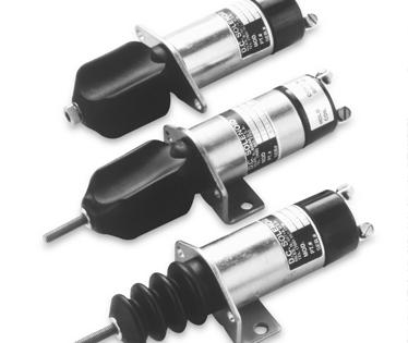
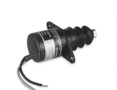
13 Dual Coil Solenoids Solenoids Features: Dual coil design for higher pull force in a smaller package than similar size single coil solenoid Customer-specified option to switch from high current pull operation to low current hold operation with internal mechanical switch or external electronic switch Hold coil provides continuous duty operation Hard chrome plated plunger and brass liner for smooth, reliable, wear-resistant operation, tested on one million cycles Corrosion resistant plated steel housing and mounting base/flange Choice of flange, threaded, or base mountings Electrical connections available with choice of screw or spade terminals, or wire/connectors Two different boot types available; bellows boot is tapered to eliminate expansion in tight spots; constant volume boot has no breather hole and so provides contaminant protection of the plunger and bore info_niles@woodward.com 11
14 Solenoids 1500 Series Models 1502, 1502ES & 1504 dual coil solenoids Pull Force Range: lbs (44-53 N) Hold Force Range: lbs ( N) 25 (110) Rated Pull Hold Model Voltage Rating* Rating* /24 VDC 10 lbs (44 N) 24 lbs (107 N) 1502ES12/24 VDC 10 lbs (44 N) 28 lbs (125 N) /24 VDC 12 lbs (53 N) 19 lbs (85 N) *At rated voltage, 68ºF (20ºC), and 1" (25.4 mm) stroke Force lbs (N) 20 (88) 15 (66) 10 (44) ES 1502 Return Spring Model 1" S1 Light lbs S2 Medium lbs 5 (22) (2.54) 0.2 (5.08) 0.3 (7.62) 0.4 (10.16) 0.5 (12.70) 0.6 (15.24) Stroke in (mm) 0.7 (17.78) (20.32) (22.86) 1 (25.4) Spring 2 Spring 1 Order Information: Complete the following model descriptions to build your Order No. ( ) Model No ES Note: 1502ES offers Base Mounting, Ungrounded Terminals and Screw Type Termination only 1504 ( ) Volts VDC VDC ( ) Mounting Style A Flange B Thread C Base D Flange ( ) Plunger Type 2 Ext. Thread Ext. Thread M-6 6 Int. Thread Int. Thread M-6 ( ) Grounding (No. of Terminals) G Grounded (1 Terminal) U Ungrounded 1502 and 1504: (2 Terminals) 1502ES: (3 Terminals or Wire Leads) ( ) Termination Type 1 Screw 2 Spade L 3 Wire Leads ( ) Boot Type B1 Constant Volume Epichlorohydrin B2 Bellows Silicone Rubber B4 Bellows Silicone Rubber B5 Constant Volume Silicone Rubber ( ) Return Spring 1") S1 Light ( lbs) S2 Medium ( lbs) When you order: Add A to your order number for the Aux Terminal option available on internally switched models. Certain combinations may not be standard models. Please contact factory to determine whether a custom-built model is required for your application. 12 phone:
15 1500 Series Mounting Styles: MOUNTING STYLE A Flange Mount.5" [13 mm] 4.7" [120 mm] ø1.5" [38 mm] 1.3" [33 mm] C.V. BOOT ø.28" [7.14 mm] THRU HOLE (2-PLACES) 2.5" [64 mm] MOUNTING STYLE B Threaded Mount.4" [10 mm] 5.5" [140 mm] 2.2" [56 mm] LOCKWASHER AND NUT ø1.5" [38 mm] Solenoids.96" [24.4 mm] TERMINAL TYPE 1 SCREW #8-32 (2-PLACES) FLANGE MOUNT PLUNGER STYLE 6 WITH 1/4-28 INTERNAL THREAD RETURN SPRING -OPTIONAL- TERMINAL TYPE 2 SPADE 1/4" (2-PLACES) 1"-20 EXTERNAL THREAD MOUNT PLUNGER STYLE 2 WITH 1/4-28 EXTERNAL THREAD MOUNTING STYLE C Base Mount MOUNTING STYLE D Flange Mount COIL LEAD COLOR: GREEN COIL LEAD COLOR: WHITE.25" FEMALE QUICK CONNECT 5.25" [133.9 mm] 4.14" [105.0 mm] 1.81" [45.9 mm] C.V. BOOT ø 1.50" [38.1 mm] 1.43" [36.2 mm] 2.58" [65.6 mm].13" [3.4 mm] PLUNGER STYLE 2 WITH 1/4-28 EXTERNAL THD. ø.27" [6.9 mm] (2-PLACES) WRENCH.375" FLATS [9.53 mm] 1.81" [45.9 mm] 1.00" [25.4 mm] 2.0" [50.8 mm] 2.5" [63.5 mm].5" [13 mm] 4.7" [120 mm] ø1.5" [38 mm] 1.3" [33 mm] AUX. TERMINAL SCREW #6-32 -OPTIONAL- TERMINAL TYPE 1 SCREW #8-32 (2-PLACES) FLANGE MOUNT ø.25" [6.4 mm] THRU HOLE (2-PLACES) BELLOWS BOOT 1.9" [48 mm] PLUNGER STYLE 6 WITH 1/4-28 INTERNAL THREAD RETURN SPRING -OPTIONAL- Specifications: Temperature Range Weight -40 F to +250 F (-40 C to +121 C) 1.0 lbs (0.5 kg) Rated Rated Pull Hold Pull Hold Coil Model Voltage Stroke Current Current Rating* Rating* Winding VDC 1" (25.4 mm) 30 A 0.7 A 10 lbs (44 N) 24 lbs (107 N) Parallel VDC 1" (25.4 mm) 16 A 0.24 A 10 lbs (44 N) 24 lbs (107 N) Parallel 1502ES 12 VDC 1" (25.4 mm) 30 A 0.7 A 10 lbs (44 N) 28 lbs (125 N) Parallel 1502ES 24 VDC 1" (25.4 mm) 16 A 0.24 A 10 lbs (44 N) 28 lbs (125 N) Parallel VDC 1" (25.4 mm) 41 A 0.76 A 12 lbs (53 N) 19 lbs (85 N) Parallel VDC 1" (25.4 mm) 22 A 0.37 A 12 lbs (53 N) 19 lbs (85 N) Parallel *At rated voltage, 68ºF (20ºC), and 1" (25.4 mm) stroke Specifications are for reference only. info_niles@woodward.com 13
 38 lbs (169 N) 1751ES12/24 VDC 25 lbs (111 N) 41 lbs (182 N) 1753 12/24 VDC 19 lbs (85 N) 42 lbs (187 N) 1753ES12/24 VDC 20 lbs (89 N) 43 lbs")
16 Solenoids 1750 Series Models 1751, 1751ES, 1753 & 1753ES dual coil solenoids Pull Force Range: lbs ( N) Hold Force Range: lbs ( N) 40 (178) 35 (156) Rated Pull Hold Model Voltage Rating* Rating* /24 VDC 24 lbs (107 N) 38 lbs (169 N) 1751ES12/24 VDC 25 lbs (111 N) 41 lbs (182 N) /24 VDC 19 lbs (85 N) 42 lbs (187 N) 1753ES12/24 VDC 20 lbs (89 N) 43 lbs (191 N) *At rated voltage, 68ºF (20ºC), and 1" (25.4 mm) stroke Return Spring Model 1" S1 Light S5 Medium 4-8 lbs 7-11 lbs Force lbs (N) 30 (133) 25 (110) 20 (88) 15 (66) 10 (44) 5 (22) (2.54) 0.2 (5.08) 0.3 (7.62) 0.4 (10.16) 0.5 (12.70) 0.6 (15.24) Stroke in (mm) 0.7 (17.78) (20.32) (22.86) 1 (25.4) 1751ES ES 1753 Spring 5 Spring 1 Order Information: Complete the following model descriptions to build your Order No. ( ) Model No ES ES ( ) Volts VDC VDC ( ) Mounting Style A Flange E Base ( ) Plunger Type 2 Ext. Thread Ext. Thread M-6 6 Int. Thread Int. Thread M-6 ( ) Grounding (No. of Terminals) U Ungrounded 1751 and 1751ES: (3 Terminals or Wire Leads) 1751, 1753 and 1753ES: (2 Terminals) ( ) Termination Type 1 Screw (1751 and 1753 only) 2 Spade (1751 and 1753 only) L 3 Wire Leads C Connector attached to 3 Wire Leads Note: Contact factory for type and availability ( ) Boot Type B1 Constant Volume Silicone Rubber B2 Bellows Silicone Rubber B4 Bellows Silicone Rubber ( ) Return Spring 1") S1 Light (4-8 lbs) S5 Medium (7-11 lbs) Available on 1751 and 1751ES only When you order: Add A to your order number for the Aux Terminal option available on internally switched models. Certain combinations may not be standard models. Please contact factory to determine whether a custom-built model is required for your application. 14 phone:
17 1750 Series Mounting Styles: MOUNTING STYLE A Flange Mount.5" [13 mm] 4.7" [119 mm] ø1.75" [44.5 mm] 1.52" [38.6 mm] C.V. BOOT ø.281" [7.1 mm] THRU HOLE (2-PLACES) MOUNTING STYLE A Flange Mount / External Switch 7.0" [178 mm] 3.8" [97 mm] ø1.75" [44.5 mm] 1.52" [38.6 mm] C.V. BOOT ø.281" [7.14 mm] THRU HOLE (2-PLACES) Solenoids ø2.50" [63.5 mm] 2.50" [63.5 mm] TERMINAL TYPE 1 SCREW #8-32 (2-PLACES) FLANGE MOUNT RETURN SPRING -OPTIONAL- PLUNGER STYLE 6 WITH 1/4-28 INTERNAL THREAD FLANGE MOUNT RETURN SPRING -OPTIONAL- PLUNGER STYLE 6 WITH 1/4-28 INTERNAL THREAD MOUNTING STYLE E Base Mount.5" [13 mm] ø1.75" [44.5 mm] 5.7" [145 mm] 3.23" [82.0 mm] C.V. BOOT 2.26" [57.4 mm] 2.00" [50.8 mm] 1.00" [25.4 mm] MOUNTING STYLE E Base Mount / External Switch 7.0" [178 mm] 4.8" [122 mm] 3.23" [82.0 mm] C.V. BOOT 2.25" [57.2 mm] 2.00" [50.8 mm] 1.00" [25.4 mm] TERMINAL TYPE 1 SCREW #8-32 (2-PLACES).281" [7.14 mm] SLOT (2-PLACES) BASE MOUNT PLUNGER STYLE 2 WITH 1/4-28 EXTERNAL THREAD RETURN SPRING -OPTIONAL- ø1.75" [44.5 mm].281" [7.14 mm] SLOT (2-PLACES) BASE MOUNT PLUNGER STYLE 2 WITH 1/4-28 EXTERNAL THREAD RETURN SPRING -OPTIONAL- Specifications: Temperature Range -40 F to +250 F (-40 C to +121 C) Weight 1.5 lbs (0.7 kg) Rated Rated Pull Hold Pull Hold Coil Model Voltage Stroke Current Current Rating* Rating* Winding VDC 1" (25.4 mm) 46 A 1.1 A 24 lbs (107 N) 38 lbs (169 N) Parallel VDC 1" (25.4 mm) 25 A 0.5 A 24 lbs (107 N) 38 lbs (169 N) Parallel 1751ES 12 VDC 1" (25.4 mm) 46 A 1.1 A 25 lbs (111 N) 41 lbs (182 N) Parallel 1751ES 24 VDC 1" (25.4 mm) 25 A 0.5 A 25 lbs (111 N) 41 lbs (182 N) Parallel VDC 1" (25.4 mm) 33 A 0.8 A 19 lbs (85 N) 42 lbs (187 N) Parallel VDC 1" (25.4 mm) 18 A 0.4 A 19 lbs (85 N) 42 lbs (187 N) Parallel 1753ES 12 VDC 1" (25.4 mm) 33 A 0.8 A 20 lbs (89 N) 43 lbs (191 N) Parallel 1753ES 24 VDC 1" (25.4 mm) 18 A 0.4 A 20 lbs (89 N) 43 lbs (191 N) Parallel *At rated voltage, 68ºF (20ºC), and 1" (25.4 mm) stroke Specifications are for reference only. info_niles@woodward.com 15
 Hold Force Range: 35-56 lbs (156-249 N) Rated Push Hold Model Voltage Rating* Rating* 1756ES12/24 VDC")
18 Solenoids 1750 Push Series Models 1756ES, 1756ESDB, 1757ES & 1757ESDB dual coil solenoids. Externally switched push models available with double boot Push Force Range: lbs ( N) Hold Force Range: lbs ( N) Rated Push Hold Model Voltage Rating* Rating* 1756ES12/24 VDC 26 lbs (116 N) 35 lbs (156 N) 1756ESDB 12/24 VDC 20 lbs (89 N) 53 lbs (236 N) 1757ES12/24 VDC 20 lbs (89 N) 37 lbs (165 N) 1757 ESDB 12/24 VDC 16 lbs (71 N) 56 lbs (249 N) *At rated voltage, 68ºF (20ºC), and 1" (25.4 mm) stroke Force lbs (N) 40 (178) 35 (156) 30 (133) 25 (110) 20 (88) 15 (66) 1756ES 1757ES 1756ESDB 1757ESDB Return Spring Model 1" S1 Light 4-8 lbs S5 Medium 7-11 lbs 10 (44) 5 (22) (2.54) 0.2 (5.08) 0.3 (7.62) 0.4 (10.16) 0.5 (12.70) 0.6 (15.24) Stroke in (mm) 0.7 (17.78) (20.32) (22.86) 1 (25.4) Spring 5 Spring 1 Order Information: Complete the following model descriptions to build your Order No. ( ) Model No. 1756ES 1756 ESDB 1757ES 1757 ESDB ( ) Volts VDC VDC ( ) Mounting Style A Flange E Base ( ) Plunger Type 2 Ext. Thread Ext. Thread M-6 ( ) Grounding (No. of Terminals) U Ungrounded (3 Terminals or Wire Leads) ( ) Termination Type L 3 Wire Leads C Connector attached to 3 Wire Leads Note: Contact factory for type and availability ( ) Boot Type B1 Constant Volume Silicone Rubber Not available on ESDB models B2 Bellows Silicone Rubber B4 Bellows Silicone Rubber When you order: Certain combinations may not be standard models. Please contact factory to determine whether a custom-built model is required for your application. ( ) Return Spring 1") S1 Light (4-8 lbs) S5 Medium (7-11 lbs) Available on 1756ES and 1756ESDB only 16 phone:
19 1750 Push Series Mounting Styles: MOUNTING STYLE A Flange Mount / External Switch 5.8" [147 mm] 4.23" [107.4 mm] PLUNGER STYLE 2 WITH 1/4-28 EXTERNAL THREAD ø.281" [7.14 mm] THRU HOLE (2-PLACES) MOUNTING STYLE A Flange Mount / External Switch, Double Boot PLUNGER STYLE 2 WITH 1/4-28 EXTERNAL THREAD FLANGE MOUNT LEAD WIRES 7.0" [178 mm] LONG RETURN SPRING -OPTIONAL- Solenoids 2.50" [63.5 mm] 2.50" [63.5 mm] ø1.75" [44.5 mm] LEAD WIRES 7.0 [178] LONG FLANGE MOUNT C.V. BOOT RETURN SPRING -OPTIONAL- 3.28" [83.3 mm] 1.75" [44.5 mm] 7.1" [180 mm] BELLOWS BOOT (2-PLACES) ø.281" [7.14 mm] THRU HOLE (2-PLACES) MOUNTING STYLE E Base Mount / External Switch MOUNTING STYLE E Base Mount / External Switch, Double Boot 5.8" [147 mm] PLUNGER STYLE 2 WITH 1/4-28 EXTERNAL THREAD 3.53" [89.7 mm] ø1.75" [44.5mm].281" [7.14mm] SLOT (2-PLACES) LEAD WIRES 7.0 [178] LONG BASE MOUNT C.V. BOOT 1.00" [25.4 mm] 2.25" [57.2 mm] RETURN SPRING -OPTIONAL- 2.00" [50.9 mm] PLUNGER STYLE 2 WITH 1/4-28 EXTERNAL THREAD 4.91" [124.7 mm] LEAD WIRES 7.0" [178 mm] LONG 7.1" [180 mm] BASE MOUNT.281" [7.14 mm] SLOT (2-PLACES) BELLOWS BOOT (2-PLACES) ø1.75" [44.5 mm] 2.25" [57.2 mm] 2.00" [50.8 mm] RETURN SPRING -OPTIONAL- 1.00" [25.4 mm] Specifications: Temperature Range Weight -40 F to +250 F (-40 C to +121 C) 1.5 lbs (0.7 kg) Rated Rated Push Hold Push Hold Coil Model Voltage Stroke Current Current Rating* Rating* Winding 1756ES 12 VDC 1" (25.4 mm) 46 A 1.1 A 26 lbs (116 N) 35 lbs (156 N) Parallel 1756ES 24 VDC 1" (25.4 mm) 25 A 0.5 A 26 lbs (116 N) 35 lbs (156 N) Parallel 1756ESDB 12 VDC 1" (25.4 mm) 46 A 1.1 A 20 lbs (89 N) 53 lbs (236 N) Parallel 1756ESDB 24 VDC 1" (25.4 mm) 25 A 0.5 A 20 lbs (89 N) 53 lbs (236 N) Parallel 1757ES 12 VDC 1" (25.4 mm) 33 A 0.8 A 20 lbs (89 N) 37 lbs (165 N) Parallel 1757ES 24 VDC 1" (25.4 mm) 18 A 0.4 A 20 lbs (89 N) 37 lbs (165 N) Parallel 1757ESDB 12 VDC 1" (25.4 mm) 33 A 0.8 A 16 lbs (71 N) 56 lbs (249 N) Parallel 1757ESDB 24 VDC 1" (25.4 mm) 18 A 0.4 A 16 lbs (71 N) 56 lbs (249 N) Parallel *At rated voltage, 68ºF (20ºC), and 1" (25.4 mm) stroke Specifications are for reference only. info_niles@woodward.com 17
 49 lbs (218 N) 2001ES12/24 VDC 22 lbs (98 N) 43 lbs (191 N) 2003 12/24 VDC 26 lbs (116 N) 51 lbs (227 N) 2003ES12/24 VDC 29 lbs (129 N) 41 lbs (182 N) *At rated")
20 Solenoids 2000 Series Models 2001, 2001ES, 2003, 2003ES dual coil solenoids Pull Force Range: lbs ( N) Hold Force Range: lbs ( N) Rated Pull Hold Model Voltage Rating* Rating* /24 VDC 21 lbs (93N) 49 lbs (218 N) 2001ES12/24 VDC 22 lbs (98 N) 43 lbs (191 N) /24 VDC 26 lbs (116 N) 51 lbs (227 N) 2003ES12/24 VDC 29 lbs (129 N) 41 lbs (182 N) *At rated voltage, 68ºF (20ºC), and 1" (25.4 mm) stroke Return Spring Model 1" S1 Light S2 Medium S4 Heavy 4-8 lbs 8-14 lbs lbs Force lbs (N) 40 (178) 35 (156) 30 (133) 25 (110) 20 (88) 15 (66) 10 (44) 5 (22) (2.54) 0.2 (5.08) 0.3 (7.62) 0.4 (10.16) 0.5 (12.70) 0.6 (15.24) Stroke in (mm) 0.7 (17.78) (20.32) (22.86) 1 (25.4) 2003ES ES 2001 Spring 4 Spring 2 Spring 1 Order Information: Complete the following model descriptions to build your Order No. ( ) Model No ES 2003ES ( ) Volts VDC VDC *Flange mounting not available for ES models. ( ) Mounting Style E Base S * Flange ( ) Plunger Type 2 Ext. Thread Ext. Thread M-6 6 Int. Thread Int. Thread M-6 ( ) Grounding (No. of Terminals) G Grounded (1 Terminal) U Ungrounded 2001 and 2003: (2 Terminals) 2001ES and 2003ES: (3 Terminals or Wire Leads) ( ) Termination Type 1 Screw L 3 Wire Leads Note: 2001ES and 2003ES only C Connector attached to 3 Wire Leads Note: Contact factory for type and availability. 2001ES and 2003ES only ( ) Boot Type B1 Constant Volume Silicone Rubber B2 Bellows Silicone Rubber B3 Constant Volume Silicone Rubber Red B4 Bellows Silicone Rubber B5 Constant Volume Silicone Rubber ( ) Return Spring 1") S1 Light (4-8 lbs) S2 Medium (8-14 lbs) S4 Heavy (12-17 lbs) Available on 2003 and 2003ES only When you order: Add A to your order number for the Aux Terminal option or C for the Conduit Cover available on internally switched models. Certain combinations may not be standard models. Please contact factory to determine whether a custom-built model is required for your application. 18 phone:
21 2000 Series Mounting Styles: MOUNTING STYLE E Base Mount.5" [13 mm] 6.3" [160 mm] 3.20" [81.3 mm] BELLOWS BOOT PLUNGER STYLE 2 WITH 1/4-28 EXTERNAL THREAD MOUNTING STYLE E Base Mount / External Switch 5.5" [140 mm] 3.20" [81.3 mm] 7.0" [178 mm] C.V. BOOT PLUNGER STYLE 2 WITH 1/4-28 EXTERNAL THREAD Solenoids 2.50" [63.5 mm] 2.50" [63.5 mm] 1.50" [38.1 mm] BASE MOUNT RETURN SPRING -OPTIONAL- ø2.00" [50.8 mm] 1.0" [24 mm] 150" [38.1 mm] RETURN SPRING -OPTIONAL- BASE MOUNT ø 2.00" [50.8 mm] 1.1" [28 mm] AUX. TERMINAL SCREW #6-32 -OPTIONAL- TERMINAL TYPE 1 SCREW #8-32 (2-PLACES) ø.281" THRU HOLE [7.14 mm] (4-PLACES) ø.281" [7.14 mm] THRU HOLE (4-PLACES) MOUNTING STYLE S Flange Mount.5" [13 mm].6.3" [160 mm] ø2.00" [50.8 mm] 2.36" [59.9 mm] C.V. BOOT PLUNGER STYLE 2 WITH 1/4-28 EXTERNAL THREAD 3.25" [82.6 mm] 3.00" [76.2 mm] AUX. TERMINAL SCREW #6-32 -OPTIONAL- TERMINAL TYPE 1 SCREW #8-32 (2-PLACES) FLANGE MOUNT RETURN SPRING -OPTIONAL-.328" [8.33 mm] SLOT (2-PLACES) 2.25" [57.2 mm] Specifications: Temperature Range Weight -40 F to +250 F (-40 C to +121 C) 2.5 lbs (1.2 kg) Rated Rated Pull Hold Pull Hold Coil Model Voltage Stroke Current Current Rating* Rating* Winding VDC 1" (25.4 mm) 44 A 0.6 A 21 lbs (93 N) 49 lbs (218 N) Series VDC 1" (25.4 mm) 23 A 0.3 A 21 lbs (93 N) 49 lbs (218 N) Series 2001ES 12 VDC 1" (25.4 mm) 44 A 0.6 A 22 lbs (98 N) 43 lbs (191 N) Parallel 2001ES 24 VDC 1" (25.4 mm) 23 A 0.3 A 22 lbs (98 N) 43 lbs (191 N) Parallel VDC 1" (25.4 mm) 60 A 0.8 A 26 lbs (116 N) 51 lbs (227 N) Series VDC 1" (25.4 mm) 37 A 0.4 A 26 lbs (116 N) 51 lbs (227 N) Series 2003ES 12 VDC 1" (25.4 mm) 62 A 0.9 A 29 lbs (129 N) 41 lbs (182 N) Parallel 2003ES 24 VDC 1" (25.4 mm) 39 A 0.5 A 29 lbs (129 N) 41 lbs (182 N) Parallel *At rated voltage, 68ºF (20ºC), and 1" (25.4 mm) stroke Specifications are for reference only. info_niles@woodward.com 19
 38 lbs (391 N) 2370ES12/24 VDC 39 lbs (173 N) 88 lbs (391 N) *At rated voltage, 68ºF (20ºC) and 1.5\" (38.")
22 Solenoids 2370 Series Models 2370 and 2370ES dual coil solenoids Pull Force Range: lbs ( N) Hold Force Range: lbs ( N) 90 (400) 80 (356) 70 (311) Rated Pull Hold Model Voltage Rating* Rating* /24 VDC 37 lbs (165N) 38 lbs (391 N) 2370ES12/24 VDC 39 lbs (173 N) 88 lbs (391 N) *At rated voltage, 68ºF (20ºC) and 1.5" (38.1 mm) stroke Force lbs (N) 60 (267) 50 (222) 40 (178) 30 (133) 2370ES 2370 Return Spring Model 1" S1 Light lbs 20 (88) 10 (44) (2.54) (7.62) (12.70) (17.78) (22.86) (27.94) (33.02) (38.1) (5.08) (10.16) (15.24) (20.32) (25.4) (30.48) (35.56) Stroke in (mm) Spring 1 Order Information: Complete the following model descriptions to build your Order No. ( ) Model No ES ( ) Volts VDC VDC ( ) Mounting Style E Base ( ) Plunger Type 2 Ext. Thread Ext. Thread M-8 x Int. Thread Int. Thread M-8 x 1.25 ( ) Grounding (No. of Terminals) G Grounded (1 Terminal) U Ungrounded 2370: (2 Terminals) 2370ES: (3 Terminals or Wire Leads) ( ) Termination Type 1 #8 Screw 3 #8 Stud 6 #10 Stud L 3 Wire Leads C Connector attached to 3 Wire Leads Note: Contact factory for type and availability ( ) Boot Type B2 Bellows Epichlorohydrin B5 Constant Volume Silicone Rubber When you order: Add A to your order number for the Aux Terminal option available on internally switched models. Certain combinations may not be standard models. Please contact factory to determine whether a custom-built model is required for your application. ( ) Return Spring 1") S1 Light ( lbs) 20 phone:
23 2370 Series Mounting Styles: MOUNTING STYLE E Base Mount.5" [13 mm] 8.3" [211 mm] 1.875" [47.63 mm] 4.37" [ mm] BELLOWS BOOT ø2.40" [61.0 mm] 3.50" [88.9 mm] 3.13" [79.4 mm] MOUNTING STYLE E Base Mount / External Switch 7.0" [178 mm] 1.875" [47.63 mm] 7.5" [191 mm] 4.37" [ mm] C.V. BOOT 3.50" [88.9 mm] 3.13" [79.4 mm] ø2.40" [61.0 mm] Solenoids.328" [833 mm] SLOT (4-PLACES) RETURN SPRING -OPTIONAL- AUX. TERMINAL SCREW #6-32 -OPTIONAL- TERMINAL TYPE 1 SCREW #8-32 (2-PLACES) BASE MOUNT PLUNGER STYLE 2 WITH 5/16-24 EXTERNAL THREAD 1.35" [34.3 mm].328" [8.33 mm] SLOT (4-PLACES) BASE MOUNT PLUNGER STYLE 2 WITH 5/16-24 EXTERNAL THREAD RETURN SPRING -OPTIONAL- 1.35" [34.3 mm] Specifications: Temperature Range -40 F to +250 F (-40 C to +121 C) Weight 5 lbs (2.3 kg) Rated Rated Pull Hold Pull Hold Coil Model Voltage Stroke Current Current Rating* Rating* Winding VDC 1.5" (38.1 mm) 58 A 1.7 A 37 lbs (165 N) 88 lbs (391 N) Series VDC 1.5" (38.1 mm) 31 A 0.6 A 37 lbs (165 N) 88 lbs (391 N) Series 2370ES 12 VDC 1.5" (38.1 mm) 58 A 1.7 A 39 lbs (173 N) 92 lbs (409 N) Parallel 2370ES 24 VDC 1.5" (38.1 mm) 31 A 0.6 A 39 lbs (173 N) 92 lbs (409 N) Parallel *At rated voltage, 68ºF (20ºC) and 1.5" (38.1 mm) stroke Specifications are for reference only. info_niles@woodward.com 21

24 Solenoids Cable Solenoid Patented, remote cable link solenoid can be used for throttle advance or shutdown requirements. Ideal for applications with space restrictions, extremely hot environments or excessive vibration. Features: Remote mount for installation away from constrained or hostile environments Assembled with Model 2003ES high-force solenoid 8-14 pound return spring standard for start/stop applications. Heavy-duty cable withstands temperature ranges of -63 F to +250 F (-53 C to +121 C) Spherical rod end with 0.237" (6 mm) diameter hole Corrosion resistant plated steel housing and mounting Coils are potted to seal entire solenoid for reliable service under extreme vibration, temperature, dirt, and moisture conditions Options include connectors, flexible conduit over leads, and Coil Commander solenoid protection modules Patented Solenoid Model 2003ES Features: 12 or 24 VDC Base mount Ungrounded 3-wire leads Return spring 8 lbs (3.6 kg) at rated voltage, 68 F (20 C) and 1" (25.4 mm) stroke Order Information: ORDER NO. SA SA Voltage 12 VDC 24 VDC E.E.C. Directive Compliance: All parts supplied by Woodward are classified as components, and therefore are not CE marked. Please contact factory direct for details on specific product compliance with 89/336/EEC and 89/392/EEC directives. 22 phone:
25 DIMENSIONS.964" PLUNGER STROKE [24.5 mm].75" [19.0 mm] ø.237" [6.02 mm] ø.47" REF [11.9 mm] 5.10" REF [129.5 mm] 3.13" REF [79.5 mm] 50.40" [ mm] LC NOMINAL SUPPORT BRACKET LOCATION FOR CABLE BULKHEAD. BRACKET LOCATION TO BE ADJUSTED BY CUSTOMER. (BRACKET NOT SUPPLIED) Cable Solenoid ø.41" REF [10.4 mm] Single Coil Solenoids.91" REF [22.9 mm] 12.0" [305 mm] 4.21" REF [106.9 mm] 41.08" REF [ mm] 9/16-18 NUT 2.756" 3.39" [70.00 mm] [86.1 mm] PAT.#378, " HEX REF [34.93 mm] "E-BASE" 1.500" [38.10 mm] 2.25" [57.2 mm] ø.345" HOLE THRU [8.76 mm] (4-PLACES) ø2.03" MAX [51.6 mm] 1.179" [29.95 mm].135" [3.42 mm] NOTE: Minimum bend radius for optimum cable life is 5" (127 mm) Specifications: At rated voltage, 68 F (20 C) and.964" (24.5 mm) stroke Voltage 12 VDC 24 VDC Pull Current 61.8 A 39.0 A Hold Current 0.85 A 0.46 A Pull Force 29 lbs (129 N) Hold Force 41 lbs (182 N) Cable Length Total Length 41.08" ( mm) 50.4" ( mm) Force vs. Stroke Force lbs (N) 90 (400) 80 (356) 70 (311) 60 (267) 50 (222) 40 (178) 30 (133) 20 (88) 10 (44) (5.08) (10.16) (15.24) (2.54) (7.62) (12.70) (17.78) Stroke in (mm) 0.8 (20.32) 0.9 (22.86) 1 (25.4) Specifications are for reference only. info_niles@woodward.com 23
26 Single Coil Solenoids 1000S Series Locking Solenoid Heavy-duty locks designed for side-load resistance in hydraulic or mechanical applications. Plunger can withstand 1500 pounds of side load in the de-energized position. Features: Single coil construction for simple electrical interface Hardened, stainless steel pin resists high shear load and increases fatigue resistance Nickel plated plunger ensures smooth, reliable operation, as well as corrosion and wear resistance Protective brass liner plunger bore provides longer operating life Rugged construction allows for operation under the most severe temperature and vibration conditions Easy installation no brackets or linkages necessary Order Information: ORDER NO. SA-4971 SA-4972 Model Continuous PWM E.E.C. Directive Compliance: All parts supplied by Woodward Products are classified as components, and therefore are not CE marked. Please contact factory direct for details on specific product compliance with 89/336/EEC and 89/392/EEC directives. 24 phone:
27 DIMENSIONS.657" [16.69 mm] (DE-ENERGIZED).487" [12.37 mm] (ENERGIZED).17" [4.3 mm] TRAVEL REF. 1000S Series Locking Solenoid O-RING/O-RING GROOVE CONFORM TO SAE J1926/3 AND SAE J515 FOR THREAD LISTED. 3/4-16 UNF-2A EXTERNAL THREAD Single Coil Solenoids ø.1917" [4.869 mm] ø1.00" [25.4 mm] MAX.16" REF [4.1 mm] 7.0" [.178 mm] 1.93" [45.0 mm].50" [12.7 mm] CORNERS ROUNDED TO ø1.094" [6 mm] Specifications: SA-4971 SA-4972 Rated Voltage 12 VDC 12 VDC Rated Temperature 68 F (20 C) 68 F (20 C) Temperature Range -40 F to F -40 F to F (-40 C to +85 C) (-40 C to +113 C) Rated Stroke 0.17" (4.32 mm) 0.17" (4.32 mm) Pull Current 100% 0.7 A 2 A max for 0.2 sec Hold Current 100% 0.7 A PWM 1.0 A average Duty Cycle 15.5 VDC max 16 VDC and 185 F (85 C) Pull Force Solenoid must pull in Solenoid must pull in plunger against return plunger against return spring at 9.5 VDC and spring at 9.5 VDC and 320 F (160 C) coil tem- 235 F (113 C) within perature, with no side 200 msec, with no side load on plunger pin load on plunger pin Hold Force Solenoid must hold in Solenoid must hold in plunger against return plunger against return spring at 9.5 VDC and spring at 16 VDC, 15% 320 F (160 C) coil duty cycle, 1000 Hz temperature PWM signal, and 235 F (113 C) Pull Coil Resistance 17.8 ohms ± 10% 5.55 ohms ± 5% Specifications are for reference only. info_niles@woodward.com 25

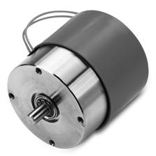
28 Single Coil Solenoids 1503S Series Typically designed for continuous duty, with single coil performing both the pull and hold function for the solenoid. Features: Continuous duty operation Hard chrome plated plunger for smooth, reliable, wear-resistant operation Brass liner plunger bore for long life Corrosion resistant plated steel housing and mounting base/flange Potted coil construction Variety of options for mounting bases/flanges, plungers, terminations, boots, and springs 100% inspected and factory tested Order Information: ORDER NO. Model Termination SA Leads E.E.C. Directive Compliance: All parts supplied by Woodward Products are classified as components, and therefore are not CE marked. Please contact factory direct for details on specific product compliance with 89/336/EEC and 89/392/EEC directives. 26 phone:
29 SA-4741 COMMON: BLACK 16-GA. WIRE 4.00±.50" (101.6 ± 12.7 mm) (2-PLACES) ø1.50" (38.1 mm) HOLD: RED 16-GA. WIRE 3.04" MAX (77.2 mm) 1.782" REF (45.3 mm) (DE-ENERGIZED) 1.28 ±.025" (32.5 ± 6.4 mm) (ENERGIZED) BRASS LINER 1503S Series.375"(9.5 mm) WRENCH FLATS ø 1.50" (38.1 mm).20" REF (5.1 mm) (2-PLACES) 2.50" (63.5 mm) 3.00" (76.2 mm) Single Coil Solenoids ø.28" (711.2 mm) (2-PLACES) POTTED COIL CONSTRUCTION WIRE STRAIN RELIEF 1.76" (44.7 mm).13" (3.3 mm) BELLOWS BOOT W/ VENT HOLE RETURN SPRING 1/4-28 UNF-2B THREAD X.62" DEEP MIN. (15.7 mm) Specifications: Rated Voltage Rated Current Rated Temperature Temperature Range Nominal Rated Stroke Pull Force Hold Force Nominal Spring Return De-energized: Energized: 12 VDC 4.7 A 68 F (20 C) -20 F to +250 F (-29 C to +121 C) 0.5" (12.7 mm) Must pull in against return spring at 9 VDC and 100 F (38 C) or 2.25 lbs min. (10 N) at rated voltage Must hold return spring at 9 VDC and 100 F (38 C) or 8 lbs (35.6 N) at rated voltage 1.16 ± 0.16 lbs (5.16 ± 0.71 N) 1.56 ± 0.25 lbs (6.94 ± 1.11 N) Pull Coil Resistance 2.53 ohms ± 10% Duty Cycle Intermittent, 25% duty cycle, 5 minutes maximum ON time Vibration Shock 15 G Hz 200 G s, 21 Hz Specifications are for reference only. info_niles@woodward.com 27

30 Single Coil Solenoids 2370S Series Typically designed for continuous duty, with single coil performing both the pull and hold function for the solenoid. Features: Continuous duty operation Hard chrome plated plunger for smooth, reliable, wear-resistant operation Brass liner plunger bore for long life Corrosion resistant plated steel housing and mounting base/flange Potted coil construction Variety of options for mounting bases/flanges, plungers, terminations, boots, and springs 100% inspected and factory tested Order Information: ORDER NO. Model Voltage Termination SA P 24 VDC Packard Metri-Pack 280 Series SA VDC Leads SA P 12 VDC Packard Metri-Pack 280 Series E.E.C. Directive Compliance: All parts supplied by Woodward Products are classified as components, and therefore are not CE marked. Please contact factory direct for details on specific product compliance with 89/336/EEC and 89/392/EEC directives. 28 phone:
31 DIMENSIONS 2.38" REF [60.5 mm] BELLOWS BOOT HARDENED CLEVIS LEAD WIRE #16 GA. ø /-.002" HOLE [ /-0.05 mm].36" [9.1 mm] 1.62±.03" [41.1±.8 mm].12" [3.0 mm] 3.00±.03 [76.2±.8 mm} 2370S Series Single Coil Solenoids 3.00±.03" [76.2±.8 mm] 2.47±.07" REF [62.7±1.78 mm] (DE-ENERGIZED) 8.50" MAX [215.9 mm] 3.45"REF [87.51 mm] (ENERGIZED) 5.25±.37" [138.4±9.4] 1/4-20 UNC WELD NUT.31" REF [7.9 mm] (4-PLACES) Specifications: SA-4973 SA-4974 SA-4975 Rated Voltage 24 VDC 24 VDC 12 VDC Rated Current 3.3 A 3.3 A 4.3 A Rated Temperature 68 F (20 C) 68 F (20 C) 68 F (20 C) Nominal Rated Stroke 0.85" (21.6 mm) 0.85" (21.6 mm) 0.85" (21.6 mm) Temperature Range -40 F to 250 F -40 F to 250 F -40 F to 250 F (-40 C to 121 C) (-40 C to 121 C) (-40 C to 121 C) Vibration 2 G Hz 2 G Hz 2 G Hz Shock 20 G s for 20 msec 20 G s for 20 msec 20 G s for 20 msec Duty Cycle Continuous up to Continuous up to Continuous up to 28 VDC & 220 F (104 C) 28 VDC & 220 F (104 C) 14 VDC & 220 F (104 C) Pull Force* N/A 16 lbs (71.2 N) N/A Push Force* 16 lbs (71.2 N) N/A 12 lbs (53.4 N) Pull Coil Resistance 7.25 ohms ± 10% 7.25 ohms ± 10% 7.25 ohms ± 10% * At rated voltage, rated stroke and 68ºF (20ºC) Specifications are for reference only. info_niles@woodward.com 29

32 Solenoid Accessories Timer Module Basics 5-Wire Coil Commander 6-Wire Coil Commander 7-Wire SSR Coil Commander Pull Coil Timer Modules Timer Modules Dual coil solenoids are constructed of two wound coils. The pull coil operates at high currents in order to provide maximum pull or push force. The hold coil retains the plunger in place after it has completed its stroke. After energizing, the pull coil must be turned off as soon as possible to prevent burnout. Timer modules protect Woodward solenoids from burnout caused by engine over cranking or the misadjustment of linkages. The protective modules energize and de-energize the solenoid pull coil within approximately seconds. Woodward makes two types of solenoid protection systems: Coil Commander modules and pull coil timer modules (PCTM). 30 phone:
33 Timer Module Basics Coil Commander Modules Coil Commanders time out a solenoid s high amperage pull coil within approximately seconds. The in-line cylindrical tube design comes in 5-, 6-, and 7-wire SSR configurations: 5-Wire Module 6-Wire Module When used with a 3-wire externally switched solenoid, the combined unit functions similarly to an internally switched solenoid without modification to existing wiring harness. Provides a quick, easy fix to prevent burnout for externally switched installations that are connected to the S terminal on the starter. 7-Wire SSR Module When used with a 4-wire externally switched solenoid, the combined unit functions similarly to an internally switched solenoid and eliminates the need for a separate solenoid relay. Stand-alone units are lightweight and need no mounting brackets. Modules are also available with solenoid attached. Maximum ON/OFF Duty Cycles for Coil Commander Modules At de-rated conditions: 125% of rated voltage and 250 F (121 C) Solenoid Accessories Continuous Intermittent 12 VDC 2 cycles/minute 4 cycles/minute for 5 minutes 24 VDC 1 cycle/minute 3 cycles/minute for 5 minutes PCTM Modules These timers protect externally switched solenoids by limiting the pull coil ON time to 1 2 second. Use of the PCTM provides enhanced solenoid performance, as an externally switched unit performs like an internally switched solenoid but with greater durability and reliability. Note: Coil Commanders and PCTM s will reduce the available pull coil voltage by approximately 1 2 to 1 volt. info_niles@woodward.com 31

34 Solenoid Accessories 5-Wire Coil Commander Provides the functionality of an internally switched solenoid when used with a 3-wire externally switched solenoid. Features: Prevents solenoid burnout due to engine over cranking or misadjustment of linkage by limiting the pull coil ON time Potted and sealed solid-state electronics Separate mounting bracket not required Stand alone plug-in or factory assembled to solenoid Patented Order Information: Stand Alone Modules Max. Current Terminations Terminations ORDER NO. Rated Voltage at 68 F (20 C) To System Harness To Solenoid SA VDC 70 A Leads Packard Weather Pack Housing No SA VDC 40 A Leads Packard Weather Pack Housing No SA VDC 70 A Packard Weather Pack Packard Weather Pack Housing No Housing No SA VDC 40 A Packard Weather Pack Packard Weather Pack Housing No Housing No SA VDC 70 A Packard Weather Pack Yazaki Housing Housing No No SA VDC 90 A Packard Weather Pack Packard Weather Pack Housing No Housing No SA VDC 60 A Packard Weather Pack Packard Weather Pack Housing No Housing No SA VDC 70 A Leads Leads SA VDC 40 A Leads Leads SA VDC 90 A Leads Leads SA VDC 60 A Leads Leads SA VDC 90 A Metri-Pack 280 Series Packard Weather Pack Housing No Housing No Built-in Modules Contact Woodward for factory assembled units Minimum quantities required for non-standard configurations. Contact factory for details. 32 phone:
35 A 5-Wire Coil Commander TERMINATION CONNECTIONS CONNECT TO SYSTEM HARNESS CONNECT TO SOLENOID C B SOLENOID ELECTRIC SHUTOFF Electric shutoff with dedicated relay for fuel solenoid + BATTERY - OFF ACC RUN/ START ON KEY SWITCH STARTER RELAY WHITE (+) BLACK (-) FUEL SOLENOID RELAY STARTER SOLENOID STARTER MOTOR COIL COMMANDER (5-WIRE) PATENT# 5,592,356 S FUEL SHUT-OFF SOLENOID RUN/ON STOP/OFF THROTTLE/CHOKE SOLENOID Throttle/choke solenoid with dedicated relay for fuel solenoid OFF + ON BATTERY - WHITE (+) BLACK SWITCH (-) THROTTLE/CHOKE THROTTLE/CHOKE SOLENOID RELAY COIL COMMANDER (5-WIRE) PATENT# 5,592,356 THROTTLE/ CHOKE SOLENOID FULL THROTTLE OR FULL CHOKE LOW IDLE OR NO CHOKE Solenoid Accessories DIMENSIONS CONNECT TO SYSTEM HARNESS 3.4 ±.5" [86 ± 13 mm] 1.82" [46.2 mm] REF..755" [19.18 mm] REF. 3.5" [89 mm] REF. 2-WAY SEALED CONNECTOR WEATHER PACK SERIES PACKARD PART NO'S.: HOUSING: # (1) TERMINAL [MALE]: # (2) SEAL: # (2) 7.6 ±.5" [193 ± 13 mm] 1.60" [40.6 mm] REF. 3-WAY SEALED CONNECTOR WEATHER PACK SERIES PACKARD PART NO'S.: HOUSING: # (1) TERMINAL [FEMALE]: # (3) SEAL: # (3) Note: Coil Commanders will reduce the available pull coil voltage by approximately 1 2 to 1 volt. CONNECT TO SOLENOID Specifications: Temperature -40 F to +250 F (-40 C to +121 C) Vibration 15 G Hz Rated Voltage 12 Volt 24 Volt Minimum Input Voltage 9 VDC F (20 C) Rated Jump Start Voltage 24 VDC 48 VDC (<5 min) Reverse Polarity Protection None Weight Approx. 4 oz. (113 g) Specifications are for reference only. E.E.C. Directive Compliance: All parts supplied by Woodward are classified as components, and therefore are not CE marked. Please contact factory direct for details on specific product compliance with 89/336/EEC and 89/392/EEC directives. info_niles@woodward.com 33

36 Solenoid Accessories A A 6-Wire Coil Commander Plugs into existing externally switched solenoid installations without wiring modification when used with optional connectors. Works with installations connected to S terminal on starter. Features: Prevents solenoid burnout due to engine over crank or misadjustment of linkage by limiting the pull coil ON time Potted and sealed solid-state electronics Separate mounting bracket not required Stand alone plug-in or factory assembled to solenoid Patented Order Information: Stand Alone Modules Max. Current Terminations Terminations ORDER NO. Rated Voltage at 68 F (20 C) To System Harness To Solenoid SA VDC 86 A Packard Weather Pack Packard Weather Pack Housing No Housing No SA VDC 86 A Leads Leads SA-4945* 9-36 VDC 86 A Yazaki Housing Male Yazaki Housing Female No No SA VDC 86 A Packard Metri-Pack 280 Packard Metri-Pack 280 Housing No Housing No SA VDC 86 A Yazaki Housing Male Yazaki Housing Female No No *For use with Kubota 1503ES solenoids Built-in Modules Contact Woodward for factory assembled units Minimum quantities required for non-standard configurations. Contact factory for details. TERMINATION CONNECTIONS CONNECT TO SYSTEM HARNESS CONNECT TO SOLENOID C B C B A C B SOLENOID E.E.C. Directive Compliance: All parts supplied by Woodward are classified as components, and therefore are not CE marked. Please contact factory direct for details on specific product compliance with 89/336/EEC and 89/392/EEC directives. 34 phone:
37 OFF START ACC RUN/ ON S TM DIMENSIONS 6-Wire Coil Commander CONNECT TO SYSTEM HARNESS CONNECT TO SOLENOID 3.4 ±.5" [86 ± 13 mm] 1.85" [74.0 mm] REF. 4.5" [114 mm] REF. ø.755" [19.18 mm] REF. 6.6 ±.5" [168 ± 13 mm] 1.60" [40.6 mm] REF. 3-WAY SEALED CONNECTOR WEATHER PACK SERIES PACKARD PART No.'s: HOUSING: TERMINAL (MALE): SEAL: WAY SEALED CONNECTOR WEATHER PACK SERIES PACKARD PART No.'s: HOUSING: TERMINAL (FEMALE): SEAL: ELECTRIC SHUTOFF Electric shutoff with dedicated relay for fuel solenoid THROTTLE/CHOKE SOLENOID Throttle/choke solenoid shown with Coil Commander wired to starter. This method requires approval from the starter motor manufacturer. + - BATTERY KEY SWITCH STARTER RELAY DEDICATED RELAY PULL WHITE BLACK COMMON HOLD RED STARTER SOLENOID STARTER MOTOR COIL COMMANDER (6-WIRE) PATENT# 5,592,356 RUN/ON STOP/OFF FUEL SHUT-OFF SOLENOID + - BATTERY OFF ACC RUN/ ON START KEY SWITCH STARTER RELAY HOLD RED PULL WHITE BLACK COMMON S STARTER SOLENOID STARTER MOTOR NOTE: DIRECT WIRING TO STARTER. CUSTOMERS MUST OBTAINAPROVAL FROM THE STARTER MOTOR MANUFACTURER BEFORE USING THIS METHOD. RUN/ON FUEL COIL COMMANDER SHUT-OFF (6-WIRE) SOLENOID PATENT# 5,592,356 STOP/OFF Solenoid Accessories RECOMMENDED CONNECTION Connection of solenoid to S terminal is acceptable with 6-wire Coil Commander. S + - STARTER SOLENOID WARNING: STARTER RELAY MUST BE RATED FOR THE COMBINED CURRENT OF THE STARTER SOLENOID AND THE FUEL SHUT-OFF SOLENOID PULL COIL. NON-RECOMMENDED CONNECTION Connection of solenoid to S terminal is not recommended. + - BATTERY OFF ACC RUN/ ON START KEY SWITCH STARTER RELAY HOLD- RED PULL- WHITE COMMON- BLACK S STARTER SOLENOID STARTER MOTOR FUEL SHUT-OFF SOLENOID BATTERY OFF ACC RUN/ START ON KEY SWITCH RUN/ON STOP/OFF NOT RECOMMENDED Specifications are for reference only. STARTER RELAY BLACK COMMON HOLD RED COIL COMMANDER (6-WIRE) PATENT# 5,592,356 WARNING: CONNECTING THE FUEL SHUT-OFF SOLENOID PULL COIL TO THE STARTER SOLENOID "S" TERMINAL IS PERMITTED ONLY FOR SOLENOIDS WITH THE 6-WIRE COIL COMMANDER. FOR SOLENOIDS WITHOUT COIL COMMANDER REFER TO WIRING INSTRUCTIONS SE info_niles@woodward.com 35 PULL WHITE STARTER MOTOR Specifications: Temperature RUN/ON STOP/OFF FUEL SHUT-OFF SOLENOID Note: Coil Commanders will reduce the available pull coil voltage by approximately 1 2 to 1 volt. -40 F to +250 F (-40 C to +121 C) Vibration 15 G Hz Rated Voltage 12 Volt 24 Volt Minimum Input Voltage 9 VDC F (20 C) Rated Jump Start Voltage 24 VDC 36 VDC (1 cycle/min for 10 min) Reverse Polarity Protection None Weight Approx. 4 oz. (113 g)

38 Solenoid Accessories 7-Wire SSR Coil Commander Provides the functionality of an internally switched solenoid when used with a 4-wire externally switched solenoid. Eliminates the need for a separate solenoid relay. Features: Prevents solenoid burnout due to engine over cranking or misadjustment of linkage by limiting the pull coil ON time Potted and sealed solid-state electronics Separate mounting bracket not required Stand alone plug-in or factory assembled to solenoid Patented Order Information: Stand Alone Modules Max. Current Terminations Terminations ORDER NO. Rated 68 F (20 C) To System Harness To Solenoid SA VDC 70 A Leads Leads SA VDC 40 A Leads Leads SA VDC 60 A Leads Leads SA VDC 86 A Packard Weather Pack Packard Weather Pack Housing No Housing No SA VDC 56 A Packard Weather Pack Packard Weather Pack Housing No Housing No Built-in Modules Contact Woodward for factory assembled units. Minimum quantities required for non-standard configurations. Contact factory for details. E.E.C. Directive Compliance: All parts supplied by Woodward are classified as components, and therefore are not CE marked. Please contact factory direct for details on specific product compliance with 89/336/EEC and 89/392/EEC directives. 36 phone:
39 A 7-Wire SSR Coil Commander TERMINATION CONNECTIONS CONNECT TO SYSTEM HARNESS CONNECT TO SOLENOID A C B D C B A C B SOLENOID SSR ELECTRIC SHUTOFF SSR electric shutoff for use with externally switched solenoids and to replace or eliminate a second solenoid relay + BATTERY - OFF START KEY SWITCH ACC RUN/ ON STARTER RELAY HOLD RED PULL WHITE BLACK COMMON S STARTER SOLENOID STARTER MOTOR FUEL SHUT-OFF SOLENOID COIL COMMANDER SSR (7-WIRE) PATENT# 5,592,356 NOTE: DIRECT WIRING TO BATTERY. RUN/ON STOP/OFF SSR THROTTLE/CHOKE SOLENOID SSR throttle/choke solenoid eliminates need for mechanical relay OFF + ON BATTERY OPTIONAL GROUND WIRE USED IN ELECTRICALLY NOISY SYSTEMS - RED (CONTROL) WHITE (+) BLACK (-) SWITCH THROTTLE/CHOKE COIL COMMANDER SSR (7-WIRE) PATENT# 5,952,356 THROTTLE/ CHOKE SOLENOID FULL THROTTLE OR FULL CHOKE LOW IDLE OR NO CHOKE Solenoid Accessories DIMENSIONS A C B 3.4 ±.5" [86 ± 13 mm] PACKARD# PIN MALE C3 3.5" [89 mm] REF.755" [19.18 mm] REF. 7.6 ±.5" [193 ± 13 mm] PACKARD# PIN FEMALE C15 Note: Coil Commanders will reduce the available pull coil voltage by approximately 1 2 to 1 volt. D C B A Specifications: Temperature -40 F to +250 F (-40 C to +121 C) Vibration 15 G Hz Rated Voltage 12 Volt 24 Volt Minimum Input Voltage 9 VDC F (20 C) Rated Jump Start Voltage 24 VDC 48 VDC (<5 min) Reverse Polarity Protection None Weight Approx. 4 oz. (113 g) Specifications are for reference only. info_niles@woodward.com 37

40 Solenoid Accessories PCTM Modules Pull coil timer modules protect externally switched solenoids by limiting the pull coil ON time. Use of a PCTM enhances solenoid performance by providing functionality of an internally switched solenoid but with greater durability and reliability. Features: 3- and 6-wire configurations for externally switched solenoids Can be mounted in any orientation or location Potted and sealed solid-state electronics Corrosion resistant Order Information: Terminations Terminations ORDER NO. Wire Configuration Rated Voltage To System Harness To Solenoid SA Wire 12 VDC Leads Leads SA Wire 24 VDC Leads Leads SA Wire 12 VDC Packard Weather Pack Packard Weather Pack Housing No Housing No SA Wire 24 VDC Packard Weather Pack Packard Weather Pack Housing No Housing No SA Wire 12 VDC Leads Leads SA Wire 24 VDC Leads Leads SA Wire 12 VDC Packard Weather Pack Packard Weather Pack Housing No Housing No SA Wire 24 VDC Packard Weather Pack Packard Weather Pack Housing No Housing No SA Wire 12 VDC Leads Packard Weather Pack Housing No SA Wire 24 VDC Leads Packard Weather Pack Housing No Minimum quantities required for non-standard configurations. Contact factory for details. E.E.C. Directive Compliance: All parts supplied by Woodward are classified as components, and therefore are not CE marked. Please contact factory direct for details on specific product compliance with 89/336/EEC and 89/392/EEC directives. 38 phone:
41 PART # SERIAL # VOLTAGE NILES, IL-60714,U.S.A. TEL.(708) PART # SERIAL # VOLTAGE NILES, IL-60714,U.S.A. TEL.(708) CURRENT BATTERY NEGATIVE ORANGE BLACK BATTERY POSITIVE BLUE SWITCH YELLOW CURRENT SOLENOID COMMON SOLENOID PULL-WHITE SOLENOID HOLD-RED SWITCHED BATTERY POSITIVE SOLENOID PULL COIL BATTERY NEGATIVE BLUE YELLOW ORANGE WHITE RED BLACK YELLOW BLUE ORANGE BLUE } } } PCTM Modules 3-Wire Pull Coil Timer Module DIMENSIONS WIRING DIAGRAM 3.00" [76.2 mm] SWITCH BATTERY POSITIVE (BLUE) 2.15" [54.6 mm] 2.50" [63.5 mm] PULL COIL TIMER MODULE } } } ø.187" [4.75 mm] THRU HOLE (2-PLACES).53" [13.5 mm] 8.0" [203 mm] EXTERNAL SWITCHED SOLENOID BLACK (COMM) SOLENOID PULL COIL (YELLOW) RELAY + BATTERY - DIMENSIONS SWITCH BATTERY POSITIVE (BLUE) SOLENOID PULL COIL (YELLOW) BATTERY NEGATIVE (ORANGE) 6-Wire SSR Pull Coil Timer Module 2.15" [54.6 mm] 3.00" [76.2 mm] 2.50" [63.5 mm] PULL COIL TIMER MODULE ø.187" [4.75 mm] THRU HOLE (2-PLACES) ORANGE (BATTERY -) LEAD WIRE #14 GA. INSULATED CROSSLINKED POLYETHYLENE LEAD WIRE #14 GA. INSULATED CROSSLINKED POLYETHYLENE 8.0" [203 mm].53" [13.5 mm] WHITE (PULL) RED (HOLD) WIRING DIAGRAM EXTERNAL SWITCHED SOLENOID BLACK (COMM) OPTIONAL CONNECTOR OPTIONAL CONNECTOR BATTERY NEGATIVE (ORANGE) - BATTERY + SWITCH POSITIVE (YELLOW) NILES, IL-60714,U.S.A. TEL.(708) BATTERY NEGATIVE ORANGE SOLENOID PULL COIL YELLOW SWITCHED BATTERY POSITIVE PART # SERIAL # VOLTAGE CURRENT PULL COIL TIMER MODULE PCTM MODULE NILES, IL-60714,U.S.A. TEL.(708) CURRENT BATTERY NEGATIVE ORANGE BATTERY POSITIVE BLUE SWITCH YELLOW SOLENOID HOLD-RED SOLENOID PULL-WHITE SOLENOID COMMON BLACK PART # SERIAL # VOLTAGE PULL COIL TIMER MODULE PCTM MODULE Solenoid Accessories BLUE (BATTERY +) RED SOL.-HOLD WHITE SOL.-PULL YELLOW (SWITCH +) BLACK SOL.-COMMON WHITE (PULL) RED (HOLD) SWITCH BATTERY POSITIVE BLUE (+) BATTERY NEGATIVE ORANGE (-) Note: PCTM s will reduce the available pull coil voltage by approximately 1 2 to 1 volt. Specifications: Temperature Input Voltage Pull Current Vibration Maximum Cycles Energized Time -40 F to +185 F (-40 C to +85 C) 12 VDC (30 VDC jump start) 24 VDC (57 VDC jump start) VDC VDC 15 G Hz 3 cycles/minute continuous 0.5 seconds Specifications are for reference only. info_niles@woodward.com 39

42 Solenoid Accessories Hardware Solenoid spring swivel In-line swivel Solenoid end cap Clevis yoke Clevis yoke bead chain assemblies PVC terminal protector Spherical rod end Connectors Solenoid Spring Swivel Provides a 12 rotational movement to compensate for minor misalignment between solenoid and linkage, and allows up to.25" overtravel Male and female connectors rotate 360 for easy installation L dimension 3.0" when using or M6 male; 3.25" when using male Solenoid Optional Return ORDER NO. Model No. Spring SA ( ) ( ) No SA ( ) ( ) Yes SA ( ) ( ) No SA ( ) ( ) Yes ø.75" [19.1 mm] SEE THREAD SELECTION L MAX. 2.35" [59.7 mm].25" [6.4 mm] OVERTRAVEL 12 SPHERICAL MOVEMENT In-line Swivel Compensates for possible misalignment between rigid linkage and solenoid plunger Mounting ORDER NO. Thread SA Male End of Swivel Thread Selection SA-4050 M6 x 1 A C E M6 Female End of Swivel Thread Selection.56" [14.2 mm] MAX..58" [14.7 mm] MAX. 30 SPHERICAL MOVEMENT 1.23" [31.2mm] 1/4-28 OR M6 X 1 INTERNAL THREAD B When you order: You will need to provide the male and female swivel thread selection 2.12" [53.8 mm] MAX D F M6 1/4-28 OR M6 X 1 EXTERNAL THREAD Solenoid End Cap Hypalon rubber end cap thoroughly seals solenoid from contaminants such as water, oil, chemicals and salts Sized for 1500, 1750, and 2000 series solenoids Hypalon is a registered trademark of DuPont Dow Elastomers. ORDER NO. SE-5601 SE-5614 SE-5559 Solenoid Model No Series 1750 Series 2000 Series 40 phone:
43 Hardware Clevis Yoke For use in customer designed linkage assemblies 2.00" [50.8 mm] ORDER NO. Mounting Thread.63" [16.0 mm].28" [7.1 mm] SA-0008-A /4-28 INTERNAL THREAD ø.26" [6.6 mm] HOLE (2-PLACES) Clevis Yoke Bead Chain Assemblies Used whenever a flexible connection is required, such as pulling a throttle lever on a gasoline engine ORDER NO. Mounting Thread SA-0293-B PVC Terminal Protector For internally switched solenoids with terminals Fits over solenoid cap to protect terminals from accidental shorting Available in end or side termination ORDER NO. SA-2968 SA-2968-UK Termination End Side 1/4-28 INTERNAL THREAD 2.00" [50.8 mm] 1.75" [44.5 mm] MAX. ø1.5" [38 mm] MAX. ø1.6" [41 mm] MAX. END TERMINATION 12.0" [300 mm] 1.00" [25.4 mm] 1.44" [36.6 mm] 2.00" [50.8 mm] SIDE TERMINATION ø1.37" [34.8 mm] Solenoid Accessories Spherical Rod End Heavy duty, low friction, nylon race ball joints for connecting solenoid linkage to fuel pump levers Available in male and female options.75" [19.1 mm] 1.69" [42.9 mm] ø.251" HOLE [6.35 mm] ORDER NO. Body Stud ø.47" [11.9 mm].75" [19.1 mm] 55 SPHERICAL MOVEMENT SA-4280 Internal None 1/4-28 INTERNAL THREAD SA-4188 Internal External SA-4232 External External Connectors For externally switched solenoids with leads Special materials and seals are used to allow the connector to withstand extreme temperature and moisture conditions For ordering information contact Woodward C B A FRONT VIEW SIDE VIEW info_niles@woodward.com 41


44 Solenoid Shutdown Systems Shutdown Kits Safe, dependable shutdown systems fit a range of engines and fuel injection pump governors. Designed for ease of installation and maintenance, kits contain solenoid and all mounting hardware for attachment to the governor housing. Features: Hold coil designed for continuous duty operation under the most severe temperature and vibration conditions Brass liner plunger bore for long life Plunger hard chrome plated for smooth, reliable, wear-resistant operation Plated steel solenoid, bracket, linkage, lever and hardware for corrosion resistance Available in 12 and 24 volt models Optional Packard Weather Pack, or Metri-Pack sealed connectors (RQV-K Bosch Kit includes Packard Weather Pack connector) Mounting hardware included for fast, easy installation Kits contain the properly selected solenoid and return spring for running and stopping engines under all conditions Solenoids are sized according to deration for hot temperature and low voltage Kits Available: RQV-K Type Bosch Kit RSV Type Bosch Kit Kubota Kit 1A (62.2 mm series engines) Kubota Kit 3A (70 and 82 mm series engines) Mitsubishi L Series Kit RSV Type Zexel Nippondenso Kit E.E.C. Directive Compliance: All parts supplied by Woodward are classified as components, and therefore are not CE marked. Please contact factory direct for details on specific product compliance with 89/336/EEC and 89/392/EEC directives. 42 phone:
45 Shutdown Kits Specifications: Solenoid Rated Voltage Ambient Temperature Weight 3-wire externally switched (ES) solenoid Internally switched solenoid also available on Kubota and RSV-Bosch kits 12 or 24 VDC -40 F to +250 F (-40 C to +121 C) Approx. 3.0 lbs (1.4 kg) Engine Series Voltage Pull Current Hold Current RQV-K Bosch A 1.1 A A 0.6 A RSV Bosch A 1.1 A A 0.5 A Kubota 1A A 0.8 A (62.2 mm series) A 0.4 A Kubota 3A A 1.1 A (70 & 82 mm series) A 0.5 A Mitsubishi L A 1.1 A RSV Zexel A 1.1 A Nippondenso A 0.6 A Solenoid Shutdown Systems Specifications are for reference only. info_niles@woodward.com 43
 9.3\" [236 mm] 2.3\" [58 mm] ORDER NO. Solenoid Model Voltage SA-4026-12 1752ES 12 VDC 2.02\" [51.4 mm] A.36\" [9.2 mm] 4.03\" [102.4 mm] 3.05\" [77.5 mm] SA-4026-24 1752ES 24 VDC ø.25\" [6.")
46 Solenoid Shutdown Systems C B Shutdown Kits RQV-K Bosch Kit Installs on a variety of engines using Bosch pumps with RQV-K governor 1752ES solenoid has built-in Packard Weather Pack connector (Housing No ) 9.3" [236 mm] 2.3" [58 mm] ORDER NO. Solenoid Model Voltage SA ES 12 VDC 2.02" [51.4 mm] A.36" [9.2 mm] 4.03" [102.4 mm] 3.05" [77.5 mm] SA ES 24 VDC ø.25" [6.4 mm] HOLE (2-PLACES) 2.83" [71.9 mm] 1.69" [42.9 mm] (2-PLACES) 1.41" [35.7 mm] 3.13" [79.5 mm] 2.05" [52.1 mm] ø.32" [8.0 mm] HOLE NOTE: Left-Hand Kit with 1752ES solenoid 44 phone:
 1.10\" [27.9 mm].96\" [24.5 mm] (2-PLACES) 2.28\" [57.")
47 Shutdown Kits RSV Bosch Kit Installs on a variety of engines and Bosch Models A, MW, and P pumps with RSV governor Right- or left-hand mounting styles ORDER NO. Right-Hand Solenoid Model Voltage SA ES 12 VDC SA ES 24 VDC SA VDC ø.240" [6.10 mm] THRU HOLE (2-PLACES) 1.10" [27.9 mm].96" [24.5 mm] (2-PLACES) 2.28" [57.9 mm] ø.250" [6.35 mm] THRU HOLE 1.52" [38.6 mm] 2.08" [52.8 mm] 4.34" [110.2 mm] Solenoid Shutdown Systems SA VDC ORDER NO. Left-Hand Solenoid Model Voltage 2.10" [53.3 mm] SA ES 12 VDC SA ES 24 VDC 7.0" [178 mm] 2.78" [70.6 mm] 4.39" [111.5 mm] (ENERGIZED) SA VDC SA VDC NOTE: Left-Hand Kit with 1751ES solenoid info_niles@woodward.com 45
 1.94\" [49.3 mm].312\" [7.")
48 Solenoid Shutdown Systems Shutdown Kits Kubota 1A Kit (62.2 mm series engines) Installs on Kubota 62.2 mm series engines Also available as hardware kit without 1753 solenoid ORDER NO. Solenoid Model Voltage SA VDC SA ES 12 VDC 7.0" [178 mm] 3.8" [97 mm] 7.187" [ mm] 3.31" [84.1 mm] 2.00" [50.8 mm] SA-4270 (Hardware only) 1.94" [49.3 mm].312" [7.92 mm] 3.43" [87.1 mm] 2.00" [50.8 mm] ø.350" [8.89 mm] HOLE THRU (2-PLACES) ø.280" [7.11 mm] HOLE THRU.28" [7.1 mm] 46 phone:
 7.10\" [180.3 mm] 7.10\" [180.3 mm] 2.27\" [57.7 mm] 2.105\" [53.47 mm].25\" SLOT [6.")
49 Shutdown Kits Kubota 3A Kit (70 & 82 mm series engines) Installs on Kubota 70 and 82 mm series engines Also available as hardware kit without 1751 solenoid ORDER NO. Solenoid Model Voltage SA VDC SA ES 12 VDC SA ES 24 VDC SA-4264 (Hardware only) 7.10" [180.3 mm] 7.10" [180.3 mm] 2.27" [57.7 mm] 2.105" [53.47 mm].25" SLOT [6.4 mm] ø.25" HOLE THRU [6.35 mm] (2-PLACES) 1.614" [41.00 mm] 3.31" [84.1 mm] Solenoid Shutdown Systems 2.062" [52.37 mm] 3.70" [94.0 mm] 47

50 Solenoid Shutdown Systems Shutdown Kits Mitsubishi L Kit Installs on Mitsubishi L Series engines directly into pump with no external linkage ORDER NO. Solenoid Model Voltage SA ES 12 VDC 7.0" [178 mm] 3.38" [85.9 mm] HEX NUT.12" [3.0 mm] ø1.75" [44.5 mm] ø.18" [4.6 mm] M30 X 1.5 EXTERNAL THREAD PLUNGER-CHROME PLATED MOUNTING STYLE "B-FLANGE" NOTE: 1751ES threaded solenoid with 30mm lock nut screws into back of pump 48 phone:
 1.")
51 Shutdown Kits RSV Zexel Nippondenso Installs on a variety of engines using Zexel or Nippondenso pumps with RSV governor Right- or left-hand mounting styles ORDER NO. Right-Hand Solenoid Model Voltage SA ES 12 VDC SA ES 24 VDC ORDER NO. Left-Hand Solenoid Model Voltage 1.13" [28.7 mm] 7.0" [178 mm] ø.250" [6.35 mm] THRU HOLE (2-PLACES) 1.43" [36.3 mm] ø.266" [6.76 mm] THRU HOLE 5.25" [133.4 mm] Solenoid Shutdown Systems SA ES 12 VDC 2.3" [58 mm] SA ES 24 VDC 3.73" [94.7 mm] 3.91" [99.3 mm] NOTE: Left-Hand Kit with 1752ES solenoid info_niles@woodward.com 49

52 Solenoid Shutdown Systems Shutdown Solenoid Kit Fuel shutdown solenoid mounts closely above the front gear housing behind the fan on Kubota D722 & Z482 engines. Features: Energized to run, fail-safe operation Hold coil designed for continuous duty operation under the most severe temperature and vibration conditions Brass liner plunger bore for long life Plunger hard chrome plated for smooth, reliable, wear-resistant operation Plated steel solenoid, bracket, linkage, lever and hardware for corrosion resistance Available in 12 and 24 volt models Mounting hardware included for fast, easy installation Order Information: ORDER NO. Solenoid Voltage SA ES 12 VDC SA ES 24 VDC Kubota Shutdown Lever: Engine must be equipped with proper shutdown lever in order to install the shutdown solenoid. Order appropriate part number from Kubota. PART NO. Engine Production Date* Before April, After April, 2001 *Contact Kubota with engine serial number E.E.C. Directive Compliance: All parts supplied by Woodward are classified as components, and therefore are not CE marked. Please contact factory direct for details on specific product compliance with 89/336/EEC and 89/392/EEC directives. 50 phone:
53 Shutdown Solenoid KUBOTA D722 & Z [23.50 mm] 5.19 [131.9 mm] [29.49 mm].276slot [7.01 mm] [16 mm].31 [7.9 mm MAX] 1.28 [32.5 mm] BELLOWS BOOT.236 [5.99 mm] n1.8 [45 mm].35 [9.0 mm] RETURN SPRING Specifications: Rated Voltage Ambient Temperature Weight 12 or 24 VDC -40 F to +250 F (-40 C to +121 C) Approx. 1.8 lbs (0.8 kg) Engine Type Voltage Pull Current Hold Current Kubota D722 & Z A 1.1 A A 0.5 A Solenoid Shutdown Systems Specifications are for reference only. info_niles@woodward.com 51

54 Electronic Speed Switches ESS Basics In 1932, Woodward introduced the first system to monitor speed. Over the years, our line of speed switches has broadened to include a wide range of electronic systems for many different markets. Typical electronic speed switch applications include: Generator Sets Starter Motors Engines Conveyors Bus Doors PTO Protection Magnetic Brake Retarders Transmissions Speed switches commonly used for crank disconnect and engine overspeed protection, which also protects the generator. A speed switch can detect starting speed and disengage the cranking motor to prevent damage. The speed switch detects the critical speed above which engines should not be operated. Engines and motors suffer damage if operated at excessive speeds. By preventing the engine from developing excessive RPM s, the speed switch protects gears, transmissions, pumps, power takeoffs, etc. Underspeed can also be a source of danger. It is often desirable to shut down a motor, an engine or a piece of equipment if the speed falls below a predetermined RPM. For example, conveyors may jam, compressors freeze, belts and drives break, lugging motors stall at critical times, motor windings overheat. Should an operator of buses require positive control to prevent the rear door from opening before the bus comes to stop, a Woodward speed system combined with a Mini-Gen signal generator would provide the control automatically. Vehicles equipped with hydraulic power take-offs protect their systems by using a Woodward speed switch to control the activation speed. A Woodward speed switch and Mini-Gen signal generator are used to monitor road speed and control the retarder activation and deactivation to save the battery. A Woodward speed switch can be used as a shift inhibitor to assure the proper transmission shifting. 52 phone:
55 Understanding the Electronic Speed Switch Basics What is a Speed Switch? How Does it Work? Electronic device that senses rotational motion and speed Can be set to switch a load or control device Obtains signal from sensor device (magnetic pickup, Mini-Gen signal generator, alternator or ignition coil) in the form of a frequency Frequency is monitored electronically within the switch When the speed or frequency reaches the desired setting or set point, the output relay tied into the control circuit is energized or switched Selecting a Speed Switch In selecting the best speed switch for controlling a particular application, the following factors should be considered: Number of Switch Points Frequency Range of Application, Setpoints, and Signal Source Most applications require only 1 or 2 switch points, some models offer 3-4 points. The frequency range of the application and setpoints are dependent upon the selection of the signal source, which in turn depends upon the operating speed and physical mounting limitations. Signal Source Options The variety of signal sources which may be used with most SSPI switches include: Magnetic Pickup Commonly used for higher speed applications. The output is a function of the gap between the pickup and the gear tooth and the peripheral velocity of the gear. Mini-Gen Signal Generator Designed to provide outstanding signal output at speeds as low as 20 RPM. Alternator Output Used in applications unable to accommodate a magnetic pickup or Mini-Gen signal generator. Ignition Output Commonly used as a source for gasoline and natural gas type engines. Setpoint Frequency = No. of Gear Teeth x Engine RPM Setpoint In Hertz 60 Setpoint Frequency = Mini-Gen RPM at Engine RPM Setpoint In Hertz 2 Setpoint Frequency = Pulley Ratio x No. of Alt. Poles x Engine RPM Setpoint In Hertz 120 Setpoint Frequency = No. of Cylinders x Engine RPM Setpoint In Hertz 120 Electronic Speed Switches info_niles@woodward.com 53
56 Electronic Speed Switches Basics Setpoint Frequency Each signal source produces a different Hertz setpoint frequency for identical engine RPM setpoints. Example: Required crank disconnect 300 RPM and overspeed of 2500 RPM. This 8-cylinder gas engine has an 80-tooth flywheel and an 8-pole alternator with a 2:1 pulley ratio. Crank Disconnect Overspeed Signal Source 300 RPM 2500 RPM Magnetic Pickup 80 x 300 = 400 Hz 80 x 2500 = 3333 Hz Mini-Gen 300 = 150 Hz 2500 = 1250 Hz 2 2 Alternator 2 x 8 x 300 = 40 Hz 2 x 8 x 2500 = 333 Hz Ignition 8 x 300 = 20 Hz 8 x 2500 = 166 Hz Reset Requirements There are four reset options available for resetting the speed switch: Automatic Reset Electrical Latch Manual Reset Adjustable Reset With the automatic reset option, the switch will automatically reset if the frequency of the input signal is lowered by 80% to 90% of the setpoint. With the electrical latch option, the relay will energize (after the setpoint has been reached) and remain energized even if the input signal frequency has been lowered to 0 Hertz. The only way to reset the unit is to remove power. With the manual reset option, the switch is supplied with a reset button. By depressing this button, the unit will be reset. With the adjustable (automatic) reset option, the switch will automatically reset at the frequency determined by the setting of the supplied reset pot. By adjusting the potentiometer, the reset can be selected anywhere between 25% and 95% of the setpoint on the majority of models. Relay Operation Standard Relay Logic Reverse Relay Logic With power applied and a signal below the setpoint, the relay will remain de-energized until the setpoint is reached. At setpoint, the relay will be energized and remain energized until reset. With power applied and a signal below the setpoint, the relay will be energized and remain energized until the setpoint is reached. At setpoint or interruption of power, the relay will de-energize and remain de-energized until reset or power is reapplied. Reverse relay logic is commonly used as part of a fail-safe system to assure power is applied to the relay during operation. 54 phone:
57 Typical Relay Operation Basics Condition Standard Relay Logic Reverse Relay Logic Power Off NO NC NO NC C C Power On NO NC NO NC C C At Setpoint NO NC NO NC C C At Reset NO NC NO NC C C Loss of Power NO NC NO NC to Switch C C Power Requirements Identify the power source variations. Determine the maximum and minimum voltage as well as transients of the power source. Load Requirements Determine the voltage and current switching requirements of the external control circuit. Consider the inductive or resistive nature of the load. If load currents in excess of 10 amps are expected, interface relays should be used. Environmental Conditions Identify the environmental conditions. Determine the maximum and minimum ambient temperatures. Also consider vibration and shock. Standard Features and Options Verify or Test Circuit Signal Loss Power Loss Terminal Protection Standard on many models, which enables the testing of the complete system while the engine is operating at a safe speed. When used, the switch will trip at approximately 67% of the setpoint. If protection from possible loss of signal is desired, the ESSB offers optional broken signal lead protection by continuously monitoring for an open or high resistance in the signal source circuit. If protection from loss of power to the electronic unit is desired, specify the reverse relay logic option. Conduit covers and terminal protectors are available to eliminate exposed connections and danger from high voltage on select models. Electronic Speed Switches info_niles@woodward.com 55

58 Electronic Speed Switches ESSB Model ESSB electronic speed switch has many years of proven service. It is engineered to provide a wide variety of features and options including up to four switch points, adjustable reset, a selection of voltage inputs and tachometer output. Features: Adjustable switch points Sealed NEMA 4 enclosure Transient and reverse polarity protection Precise repetitive speed switch points Automatic, manual or remote manual reset Power loss protection DC output for Model 30 Tach (1 ma) 8 40 VDC; 64 VDC; VDC; or VAC power Broken signal lead protection Standard or reverse relay logic Lockwire seal Conduit cover Vibration isolation kit accessory Order Information: Complete the following model descriptions to build your Order No. ESS B ( ) ( ) ( ) ( ) Electronic Speed Switch Switch model 1, 2, 3 or 4 Number of switch points Note: for each switch point, specify set and reset frequency: a) Hertz and increasing or decreasing speed direction b) Standard or reverse relay logic c) Optional special reset differential adjustment d) Optional broken signal lead protection A Automatic reset M Manual reset on one switch point R Remote manual switch T Tachometer Model 30 option Note: specify scale and rated speed C Conduit cover option When you order: You will need to provide the power supply voltage E.E.C. Directive Compliance: All parts supplied by Woodward are classified as components, and therefore are not CE marked. Please contact factory direct for details on specific product compliance with 89/336/EEC and 89/392/EEC directives. 56 phone:
![1 2 J FRONT VIEW Electrical Specifications: ESSB -OPTIONAL- MANUAL RESET BUTTON -OPTIONAL- TACK ADJUST ACCESS SCREW.33" [8.4 mm] MAX. LUG ACCESS SYNCHRO-START 7.56" [192.0 mm] MAX. 11 6.75" [171.](/docs-images/77/76100079/images/59-0.jpg "5 mm] 12 13 3 4 5 6 14 7 15 8 16 9 ø.31\" [7.9mm] HOLE (4-PLACES) REMOVE ONLY FOR 17 PRODUCTS, INC. SUBSIDIARY OF KNOWLES ELECTRONICS, INC.")
![18 AUTHORIZED ADJUSTMENTS 19 20 10 #8-32 TERMINAL SCRE (10-PLACES) 3.00" [76.2 mm] 4.00" [101.6 mm] MAX.](/docs-images/77/76100079/images/59-1.jpg "COVER PLATE FOR SWITC SET POINTS AND RESET POTENTIOMETERS Power Input 8 40 VDC 64 VDC 100 140 VDC 100 130 VAC Reverse Polarity Protection 1000 VDC Maximum Current (2 ch.")
59 1 2 J FRONT VIEW Electrical Specifications: ESSB -OPTIONAL- MANUAL RESET BUTTON -OPTIONAL- TACK ADJUST ACCESS SCREW.33" [8.4 mm] MAX. LUG ACCESS SYNCHRO-START 7.56" [192.0 mm] MAX " [171.5 mm] ø.31" [7.9mm] HOLE (4-PLACES) REMOVE ONLY FOR 17 PRODUCTS, INC. SUBSIDIARY OF KNOWLES ELECTRONICS, INC. 18 AUTHORIZED ADJUSTMENTS #8-32 TERMINAL SCRE (10-PLACES) 3.00" [76.2 mm] 4.00" [101.6 mm] MAX. COVER PLATE FOR SWITC SET POINTS AND RESET POTENTIOMETERS Power Input 8 40 VDC 64 VDC VDC VAC Reverse Polarity Protection 1000 VDC Maximum Current (2 ch VDC) 12 Volt 24 Volt Operating 200 ma 220 ma Standby 50 ma 60 ma Signal Input Minimum: 1.2 VRMS Impedance: 2K ohms SIDE VIEW Relay Contact Ratings Resistive Load: Inductive Load: Overspeed Response Time 0.1 to 10 A 28 VDC 0.1 to 8 A 28 VDC 100 milliseconds typical GLASS FILLED MOLDED COVER DUST AND MOISTURE COVER ALUMINUM CASE.31" [7.9 mm] MAX. 6.00" [152.4 mm] MAX. 4.75" 4.37" [120.7 mm [111.0 mm] MAX. MAX. Setpoint Reset Automatic: Automatic Adjustable: Setpoint Stability 80% to 90% of setpoint 50% to 98% of setpoint 0.8% over voltage range and 0.01% per F typical Mechanical Specifications: Accessories Vibration Isolator ORDER NO. Mounting Studs SA x 5 8" Operating Temperature Vibration The vibration isolator kit is recommended for mounting ESSB speed switches on or near engines wherever vibration exceeds 5 G s 20 to 500 Hertz. Proper installation will reduce vibration by as much as 80%. Mounting studs are x 5 8" permitting mounting on 1 4" thick plate. Specifications are for reference only. -40 F to F (-40 C to + 85 C) 4 G s from 9 to 200 Hz Shock4 foot drop test Case NEMA 4 high impact molded enclosure Weight 4.5 lbs (2 kg) Electronic Speed Switches info_niles@woodward.com 57
60 Electronic Speed Switches ESSD The ESSD speed switch is designed to provide overspeed or underspeed protection, crank disconnect, shift inhibiting on diesel engines, and brake retarding on trucks and buses. DISCONTINUED Effective Features: Economical single channel speed switch Compact, rugged construction Potted, solid state components Normally open or normally closed switch Adjustable reset Wide speed range from 20 RPM up to 10 khz Order Information: Indicate switch action to complete your Order No. Set Point Signal Source Signal Source Signal Source Frequency Range Mini-Gen Mini-Gen Magnetic ORDER NO. Hertz 44 Gauge 37 Gauge Pickup SA-2657-( ) >10 X SA-2658-( ) 12.5 to 68 X SA-2659-( ) 69 to 357 X SA-2660-( ) 358 to 1330 X X SA-3316-( ) 1331 to 3200 X SA-3317-( ) 3201 to 8000 X Switch Action NO Normally open NC Normally closed OA Normally open w/ adjustable reset CA Normally closed w/ adjustable reset E.E.C. Directive Compliance: All parts supplied by Woodward are classified as components, and therefore are not CE marked. Please contact factory direct for details on specific product compliance with 89/336/EEC and 89/392/EEC directives. 58 phone:
61 PRODUCTS, INC. R FRONT VIEW Electrical Specifications: ESSD 2.12" [53.8 mm] NILES, IL-60714,U.S.A. P/N RESET PT.( HZ ) 3.88" [98.6 mm] 3.38" [85.9 mm] MODEL ESSD ELECTRONIC SPEED SWITCH TEL.(708) S/N R.P. S.P. INC INC SET PT.( HZ ) PATENTED ø.187" [4.75 mm] HOLE (4-PLACES) 1.63" 1.12" [41.4 mm] [28.4 mm] Power Input VDC Maximum Current (2 ch.8 40 VDC) 12 Volt 24 Volt Standby 3 ma 6 ma Signal Input Minimum: 1.2 VRMS Impedance: 22K ohms (Nominal) TERMINAL BLOCK WITH #6-32 PAN HD. SCREW (4-PLACES) Switching Capability External Load Resistance Maximum: 1 A DC continuous 12 VDC: 14 to 330 ohms 24 VDC: 28 to 1200 ohms SIDE VIEW Setpoint Reset Automatic: Automatic Adjustable: 70% to 90% of setpoint 50% to 98% of setpoint 2.88" [73.2 mm] Mechanical Specifications:.61" [15.5].03" 1.38" [35.1 mm] [.8 mm] Operating Temperature Vibration -40 F to F (-40 C to + 85 C) 5 G s from 20 to 500 Hz Shock4 foot drop test Case Metal drawn Potted electronics for environmental protection Nickel-plated terminals humidity and salt spray resistant Weight.27 lbs (.12 kg) Specifications are for reference only. Electronic Speed Switches info_niles@woodward.com 59

62 Electronic Speed Switches ESSE Series Single or dual switches to monitor and control critical speed functions. Applications include crank disconnect or overspeed protection on diesel engines, transmission shift inhibiting, and PTO protection. Features: Standard or reverse relay operation Field adjustable set and reset switch points High noise immunity Latch, automatic, manual or adjustable resets (automatic or latch are field selectable) Reverse polarity protection Mini-Gen signal generator, magnetic pickup, alternator or ignition coil for signal input Test circuit (trips at 67% ± 10% of setpoint) Potted for in-field reliability, exposed applications, and hostile environments Field selectable setpoint range Order Information: Complete the following model descriptions to build your Order No. ESS E ( ) ( ) ( ) Electronic Speed Switch Switch model 1 Single setpoint 2 Dual setpoints Note: for each setpoint, specify setpoint frequency (see Basics ) and signal source (Mini-Gen signal generator, magnetic pickup, alternator, or ignition coil on gas engines). Setpoint #1 reset option (Options for single set point) L Latch-up A Automatic reset P Automatic adjustable reset M Manual reset Setpoint #2 reset option (leave blank for single set point) L Latch-up A Automatic reset P Automatic adjustable reset M Manual reset When you order: Also specify speed range 1 or 2 from the chart below. 1 2 Standard Inputs Hz ,000 Hz Ignition Input Hz Hz E.E.C. Directive Compliance: All parts supplied by Woodward are classified as components, and therefore are not CE marked. Please contact factory direct for details on specific product compliance with 89/336/EEC and 89/392/EEC directives. 60 phone:
63 PRODUCTS, INC. C 8-40 VDC NO NC SIGNAL TEST INC. SET POINT INC. RESET POINT C 8-40 VDC NO SW1 TEST NC C NO SW2 INPUT SIGNAL NC SW1 SW2 SET POINTS PRODUCTS, SW1 SW2 RESET POINTS INC. R ESSE Series ESSE-1 ESSE " [165.1 mm] MAX. 5.70" [144.8 mm] FRONT VIEW 7.7" [196 mm] MAX. 7.0" [177.8 mm] FRONT VIEW ø.27" [6.9 mm] HOLE (4-PLACES) R INPUT " 4.0" [102 mm] MAX. [50.8 mm] ø.27" [6.9 mm] HOLE (4-PLACES) " [117 mm] MAX. 3.50" [88.9 mm] MAX TERMINAL BLOCK WITH #6-32 PAN HD. SCREW (8-PLACES) 5.12" [130.0 mm] MAX. SIDE VIEW TERMINAL BLOCK WITH #6-32 PAN HD. SCREW (12-PLACES) 6.4" [163 mm] MAX. -OPTIONAL- MANUAL RESET BUTTON SIDE VIEW 1.25" [32.0 mm] MAX..25" [6.4 mm] 1.55" [39.4 mm] MAX. 1.25" [32.0 mm] MAX..25" [6.4 mm] 1.55" [39.4 mm] MAX. Electrical Specifications: Mechanical Specifications: Power Input 8 40 VDC (40 80 VDC optional on ESSE-2) Power Supply 900 volts for 100 Transient Protection microseconds (exponential decay) Reverse Polarity Protection 1000 VDC Maximum Current for ESSE-1 12 Volt 24 Volt Operating: 125 ma 140 ma Standby: 30 ma 45 ma for ESSE-2 12 Volt 24 Volt Operating: 200 ma 220 ma Standby: 30 ma 45 ma Signal Input Minimum: 1.2 VRMS Maximum: 130 VRMS Impedance: 33K ohms (nominal) Relay Contact Ratings Resistive Load: 0.1 to 10 A 28 VDC Inductive Load: 0.1 to 8 A 28 VDC Overspeed Response Time Setpoint Reset Setpoint Stability 100 milliseconds (typical) Automatic (80% to 90% of setpoint) Automatic Adjustable (25% to 95% of setpoint) Electrical Latch Manual Reset For an input voltage range of 9V to 40V and for a temperature range of +14 F to +185 F (-10 C to +85 C), the ESSE Series shall typically be less than 1% or 8 Hz, whichever is greater. The unit performs to -40 F (-40 C). Operating Temperature Vibration -40 F to +185 F (-40 C to +85 C) 4 G s from 20 to 500 Hz Shock4 foot drop test Case Cast aluminum 1 4" wall thickness Potted electronics for environmental protection Nickel-plated terminals humidity and salt spray resistant Weight of ESSE lbs (.5 kg) of ESSE lbs (0.9 kg) Specifications are for reference only. Electronic Speed Switches info_niles@woodward.com 61
64 Electronic Speed Switches EPS 1000 The EPS 1000 is a programmable, three-channel equipment protection module designed to perform a variety of functions simultaneously. It is especially suited for engine protection, sequenced operations, and critical timing applications. It can also be used for unattended engine starting using autocrank and glow plug functions. Features: PC programmable, microprocessor based for accurate and stable set points Two-piece enclosure allows either recessed panel mounting or base mounting (Patent applied for) Front panel LED s provide instant visual data on operational status Three output channels for independent configuration of various actions Each channel can be configured in one of three modes: 1. Speed Switch 2. Autocrank Controller 3. Glow Plug Controller Speed signal input is user selectable for magnetic pickup, ignition, or Hall Effect sensor Autocrank mode allows programming for crank time, rest time, and maximum crank attempts Glow plug mode controls glow plug ON time Test verify function permits testing of relay at 70% of set point (programmable 0 to 99% of set point) Normal or reverse relay logic is configurable by user Six switch inputs plus engine speed input provide versatile programming Protection switch inputs (EP) can be enabled at preset (programmable) RPM after preset time delay Two auxiliary outputs indicate status and fault codes Engine status indicator displays engine failure codes to aid in troubleshooting engine problems Order Information: ORDER No. SA-4478 SA-4479 Description EPS 1000 Module EPS Calibration Tool Kit Includes interface module, program diskette, RS-232 cable, and Operator s Manual E.E.C. Directive Compliance: All parts supplied by Woodward are classified as components, and therefore are not CE marked. Please contact factory direct for details on specific product compliance with 89/336/EEC and 89/392/EEC directives. 62 phone:
65 EPS 1000 Electrical Specifications: Power Input 9 30 VDC, reverse polarity protected Electromagnetic Compatibility ISO 14982:1998/E EMI Immunity 30 V/M 20 MHz to 1000 MHz (ISO 14982:1998/E) Nominal Operating Current 12 Volt 24 Volt Operating: 140 ma 120 ma Standby: 25 ma 40 ma Relay Contact Ratings Resistive Load: 0.1 to VDC Inductive Load: 0.1 to 8 28 VDC Auxiliary Outputs Aux 1 and Aux 2: 200 ma maximum Mechanical Specifications: Operating Temperature Vibration -40 F to +185 F (-40 C to +85 C) 4 G s from 40 to 2000 Hz Shock10 G 45 Hz Case UV, chemical resistant, and UL 94 V-0 flame retardant. Encapsulated for reliability against harsh environments Calibration Requires interface adapter and software for calibration setup. Terminations Weight Euro style terminal block.85 lbs (.386 kg) Unique, Patented Enclosure: Two-part enclosure accommodates either panel or base mounting for convenient, clutter-free installation. Case Reversible Frame Lead wires to 21 terminals exit unobtrusively from bottom of case Terminal descriptions easily identified on side of case LED s and engine failure codes prominently displayed on front panel Snap ledges secure case to frame When attached to top of case, assembly can be installed below the surface in a cutout in the panel (panel mount) When attached to bottom of case, assembly can be mounted on top of panel surface (base mount). Built-in aperture allows a convenient exit for wires and/or connections. PANEL MOUNT BASE MOUNT FRAME SCREWS TO SECURE ASSEMBLED ENCLOSURE TO PANEL 5.21" (132.3 mm) CASE 3.88" (98.5 mm) SCREWS TO SECURE ASSEMBLED ENCLOSURE TO PANEL PANEL CASE LEAD WIRES Specifications are for reference only. CASE SNAP TAB TO SECURE FRAME TO CASE WIRE EXIT PANEL FRAME 1.44" (36.6 mm) SNAP LEDGE TO SECURE CASE TO FRAME Dimensions: 5.21" L x 3.88" W x 1.44" D (132.3 mm L x 98.5 mm W x 36.6 mm D ) Electronic Speed Switches info_niles@woodward.com 63
66 Speed Sensors Magnetic Pickups Convert engine speed to an AC voltage. Compatible with Woodward electronic governing systems and speed switches Features: No moving parts Self powered 5 8 and 3 4 thread sizes Withstands extreme temperature range Endures shock and vibration Choice of wire leads or cable connectors Order Information: Without Cable Assembly* Mounting Overall Coil Resistance Inductance Output Voltage Output Voltage ORDER NO. Thread Length (mm) 78 F 1 Khz Peak-to-Peak VRMS SA " (66.6) 144 to SA-2171A " (92.2) 144 to With Cable Assembly Mounting Overall Coil Resistance Inductance Output Voltage Output Voltage ORDER NO. Thread Length (mm) 78 F 1 KHZ Peak-to-Peak VRMS SA " (76.2) 360 to SA " (76.2) 40 to Operating Temperature: -65 F to 225 F (-54 C to 107 C) Storage Temperature: -100 F to 225 F (-73 C to 107 C) Test Conditions: Airgap: 0.015, Surface speed: 300 in/sec, Test wheel gear: 8 pitch, Load: 2.2k ohms. *See facing page for ordering information Specifications are for reference only. E.E.C. Directive Compliance: All parts supplied by Woodward are classified as components, and therefore are not CE marked. Please contact factory direct for details on specific product compliance with 89/336/EEC and 89/392/EEC directives. 64 phone:
67 Magnetic Pickups SA " [4.6 mm] 1.66" [42.2 mm] 2.53" [64.3 mm].76" [19.3 mm] SA /4"-16" UNF-2A THREAD HEX NUT Speed Sensors.87" [22.1 mm] LOCKNUT (2-PLACES) 5/8"-18" UNF-2A THREAD 1.125" [28.6 mm].187" [4.8 mm] 3.0" [76.2 mm] NOTE: Chisel Tip SA-2170 is suggested for flywheel teeth with very fine pitch Two wires, open lead SA-2171A SA " [22.1 mm] 3.63" [92.2 mm] 5/8"-18' UNF-2A THREAD HEX NUT 2.50" [63.5 mm] LOCKNUT.76" [19.3 mm].106" [2.7 mm].18" [4.6 mm] 5/8"-18" UNF-2A THREAD.75" [19.1 mm] 3.0" [76.2 mm] Two wires, open lead Use Woodward magnetic pickups with electronic speed switches for the input signal normally obtained from a gear tooth. Models SA-4423 and SA-4424 come with cable assembly for connection to the speed switch. For connection of Models SA-2170 and SA-2171A, cable lengths from 3 to 50 feet are available. Accessories Connector and Cable Assembly Used with SA-2170 and SA-2171A only. Order separately. CONNECTOR AND CABLE ASSEMBLY ORDER NO. SA SA SA SA SA SA SA SA SA Cable Length 3' (0.9m) 8' (2.4m) 10' (3.1m) 14' (4.3m) 15' (4.6m) 20' (6.1m) 30' (9.2m) 35' (10.7m) 50' (15.3m) info_niles@woodward.com 65


68 Speed Sensors Mini-Gen Signal Generator The Mini-Gen signal generator mounts on the transmissions of buses and trucks to measure road speed or on diesel engines to measure engine speed. Features: Mounts on standard SAE , General Motors, and E1 & E2 DIN tachometer outputs Non-feed thru models come standard with 1 4" male tab Compact, only 1 3 4" in diameter Long, reliable life under continuous speeds as high as 4000 RPM Usable signal at speeds below 20 RPM (10 Hz) Output signal frequency 1 2 of shaft RPM Rugged zinc die cast construction Heavy duty, two-conductor cable on feed-thru models Plated for protection against moisture, salt and dirt Environmentally sealed Optional connectors available Patented design Signal Generator Output: 50 Mini-Gen Timing: PERIOD VRMS MINIMUM SHAFT SPEED RPM THOUSANDS 22K LOAD 37 GA. PEAK OUTPUT ZERO ZERO CROSSING Sinusoidal 1000 RPM (Mini-Gen shaft speed) = 500 Hz 1. Voltage output = 25 V peak (RMS = 17.7 volts) 2. Timing between zeroes = 1 millisecond 3. Timing between periods = 2 milliseconds Timing variation between zero crossing = 7% 66 phone:
 (No Load) 1750 RPM Minimum 25 VRMS Maximum")
69 Mini-Gen Signal Generator RUGGED CONSTRUCTION STRAIN RELIEF HI-TEMP SHIELDING CABLE NICKEL PLATED FEMALE DRIVE TANG ZINC DIE-CAST HOUSING O SHAFT SEAL Speed Sensors HOUSING GASKET SEAL O RING SEAL ONE PIECE MOLDED MAGNET AND SHAFT ASSEMBLY SHAFT CUP SEAL NICKEL PLATED MALE DRIVE TANG Electrical Specifications: Mechanical Specifications: Output (37 GA) (No Load) 1750 RPM Minimum 25 VRMS Maximum 55 VRMS Resistance (37 GA) 210 ohms +15% Hi Pot 600 VDC 60 Pole Magnet 4000 RPM maximum Consult factory for high RPM applications and alternate coil construction for higher output. Operating Temperature Thread Torque Lead Pull Test (feed-thru) Vibration Mechanical Shock Environmental -40 F to F (-40 C to +107 C) 15 ft. lbs (20.3 Nm) maximum 10 lbs (44.5 N) maximum 20 G s at Hz Withstands 3 drops to concrete from 3 feet Exposure to moisture, salt, fuel oil, lubricants, or transmission fluid will not degrade performance or shorten life Specifications are for reference only. info_niles@woodward.com 67
70 Mini-Gen Signal Generator Speed Sensors Three Mounting Drives The Mini-Gen s non-feed thru or feed thru mounting styles permit its use with practically any engine, transmission, tachometer or speedometer manufactured throughout the world. 1. SAE Mounting MGO Non-feed Thru Mounting End SA-2650A 1.13" [28.4 mm] HEX 7/8-18 INTERNAL THREAD MGO-1 Feed Thru Mounting End SA-2652A "A" "A" 7/8-18 EXTERNAL THREAD.41"[10.4 mm].56" [14.2 mm] 2. General Motors Engine Mounting MGY Non-feed Thru Mounting End SA-2731A MGW Non-feed Thru Mounting End SA-2772A ø.34" [8.6 mm] HOLE (2-PLACES) 2.22" [56.4 mm] ø.40" HOLE [10.2 mm] (6-PLACES) "B".19" [4.8 mm] 2.94" [74.7 mm] ø1.50" [38.1 mm] r.43" [10.9 mm] ø"a".226" [5.74 mm] SQ. DRIVE.12" [3.0 mm] ø5.75" [146.1 mm].226" [5.74 mm] SQ. DRIVE DIM. A B INCHES 4.56 DIA MM 11.5 DIA Metric Mounting MGJ Non-feed Thru Mounting End SA-2685A M22 x 1.5 SA-2888A M18 x 1.5 M18 X 1.5 AND M22 X 1.5 INTERNAL THREAD MGJ-1 Feed Thru Mounting End SA-2763A M22 x 1.5 E2 DIN E1 DIN M22 X 1.5 EXTERNAL THREAD 68 phone:
71 SQUARE DRIVE TANG Mini-Gen Signal Generator Drive Tangs Nickel plated, round or square drive tangs for use with SAE mounting Mini-Gens. To select appropriate drive tang, match Dimension A from mounting drive diagram with Part No. from charts below. ROUND DRIVE TANG Speed Sensors FEMALE MALE FEMALE MALE Order Information: Mounting Drive Mounting Drive Designation Style SA-2650A SAE MGO Non-feed thru SA-2652A SAE MGO-1 Feed thru SA-2731A General Motors MGY Non-feed thru SA-2772A General Motors MGW Non-feed thru (large ring) SA-2685A Metric (M22x1.5) MGJ Non-feed thru SA-2888A Metric (M18x1.5) MGJ Non-feed thru SA-2763A Metric (M22x1.5) MGJ-1 Feed thru Drive Tang Option: For use on SAE mounting drives only (MGO, MGO-1) Square Drive Tangs ORDER NO. ORDER NO. Dimensions Male Female A (mm) SA-2676 SA " (2.64) SA-2633 SA " (3.81) SA-2634 SA " (4.90) Round Drive Tangs ORDER NO. ORDER NO. Dimensions Male Female A (mm) SA-2677 SA " (3.86) SA-2678 SA " (4.75) SA-2679 SA " (5.16) SA " (4.75) Extended Metric Drive Tangs ORDER NO. Termination Specifications SA-2962 Male E2 DIN SA-2961 Female E2 DIN Note: Non-feed thru models come standard with 1 4" male tab. Lead wire with connector is available as an option. info_niles@woodward.com 69


72 APECS Basics APECS Basics A guide to help in the selection of your electronic engine governing system Understanding APECS The Advanced Proportional Engine Control System (APECS) provides isochronous engine governing through a wide speed range. The system consists of a powerful microprocessor-based controller driving a precision proportional actuator that is connected to the engine s throttle. The APECS controller product line is comprised of the 2000, 3000, 4000, 4500, and 5000 Series models. Applications APECS engine governing systems expand speed control functions in diverse applications: Power Generation Marine Construction Industrial Automotive Agriculture/Forestry Gensets/Compressors Isochronous governing Single or two-speed control Construction Equipment Single or multi-speed control Design flexibility Aerial Work Platforms Multi-speed control from operator s position 70 phone:
73 Advanced Proportional Engine Control System MODEL 3100 Programmable Engine Controller For Magnetic Pickup TM - - APECS Components and Functions Understanding APECS State-of-the-art APECS digital electronic governor system provides the flexibility to solve the most complex engine control applications. Here s how it works: APECS WITHIN CLOSED LOOP SYSTEM ENGINE SPEED SIGNAL SPEED SENSOR PROPORTIONAL ACTUATOR SPEED SWITCH APECS CONTROLLER Red Black White Wht/Blk Blue Green Violet Gray Yellow Orange + + Battery Actuator + Magnetic - Pickup Speed Select 1 Speed Select 2 Tx Service Rx Tool PWM OUTPUT C B A CALIBRATION TOOL APECS Basics POWER IN Note: See component definitions below APECS Components Speed Sensor APECS Controller The controller processes the speed signal received from the speed sensor, usually a magnetic pickup, and compares it to the desired speed setting. The powerful microprocessor-based controller is the brain of APECS. Speed Select Switch More than one speed can be selected by attaching an external switch (optional) (external pot on Series 2000). APECS Calibration Tool The calibration tool is used to configure and adjust your system. It allows (Series 3000, 4000, 4500, & 5000) interactive, real-time display of engine speed on your computer. Proportional Actuator* The output of the controller is a pulse width modulated signal to the actuator. The actuator converts the signal to an output shaft position, proportional to the amount of current in the coil. *Actuator must be ordered separately. See Linear Proportional Actuators, pages 84-89, for ordering information. info_niles@woodward.com 71
74 APECS Basics APECS Series Feature Comparison APECS Features APECS 2000 APECS 3000 APECS 4000 Type of speed control Isochronous Isochronous User selectable isochronous or droop governing Speed signal input options Magnetic pickup Magnetic pickup, Magnetic pickup, Hall effect, Hall effect, coil-type ignition, coil-type ignition, magneto ignition magneto ignition Electrical connections Screw type Open lead Connector External speed command Analog with Digital: 2 switch Analog and Digital: external pot inputs for 4 Can select discrete set analog (external pot), speeds or increase/ digital (2 switch inputs) decrease set speed or combination of both Overspeed shutdown, 25% overspeed All programmable All programmable underspeed shutdown Shutdown only Gain setting method Potentiometer Computer Computer with external remote master gain pot Gain adjustments Proportional, PID PID and Master Integral, Derivative, (PID) PC interface On-screen calibration, On-screen calibration, interactive real time interactive real time Programmable engine Ramp rates, Ramp rates, speed responses warm-up time warm-up time Drive-by-wire Pedal position sensor input with optional idle verification switch input PTO enable switch Yes Programmable auxiliary Autocrank, outputs crank disable, engine shutdown, remote status lamp, PTO enabled lamp 72 phone:

 for ordering information. Magnetic Pickups Magnetic pickup speed sensor converts mechanical motion to an AC voltage without external power.")

75 APECS Accessories APECS Calibration Tool The calibration tool provides the means of configuring and adjusting your system through software. An interface module connects the controller to your computer. Calibration wizard makes set-up easy Graphs engine speed on screen, in real time, during calibration Last settings are retained in controller, even after shutdown Please see Controllers, pages 74-83, (APECS 3000, 4000, 4500, & 5000) for ordering information. Magnetic Pickups Magnetic pickup speed sensor converts mechanical motion to an AC voltage without external power. It transmits a signal each time a gear tooth passes near the center pole piece. APECS Basics 5/8 and 3/4 UNF sizes Endures shock and vibration and extreme temperature range Choice of wire leads or sealed connector Please see Speed Sensors, pages 64-69, for ordering information. Linkage and Mounting Hardware Linkage connects the actuator shaft to the engine control lever. A good linkage contributes to accurate, stable, and responsive performance with minimal play and friction. Allows for minor misalignments Minimal friction, binding and backlash Hardware for longer and shorter linkages Please see Actuator Accessories, pages , for ordering information. WARNING: An overspeed shutdown device, independent of the APECS system, should be provided to prevent loss of engine control that may cause personal injury or equipment damage. info_niles@woodward.com 73
76 APECS Controllers APECS 2000 The powerful microprocessor-based controller of the APECS (Advanced Proportional Engine Control System) monitors the actual speed of the engine through a speed sensor, compares the actual speed with the desired speed, then sends a pulse width modulated signal to the precision proportional actuator to maintain the desired speed. Features: Proportional, Integral and Derivative control (PID) Isochronous governing ± 0.25% (20 turn setpoint) Remote speed setpoint ( ± 10% speed change or 0 100% of internal setpoint) Surface mount technology Signal source: magnetic pickup Electrostatic discharge protection Reverse polarity protection Protection against miswiring Diagnostics for broken wire, overspeed, and internal component check Engine compartment mountable and can be used with all sizes of APECS actuators Rugged case potted for environmental protection Order Information: ORDER NO. Model SA E.E.C. Directive Compliance: All parts supplied by Woodward are classified as components, and therefore are not CE marked. Please contact factory direct for details on specific product compliance with 89/336/EEC and 89/392/EEC directives. 74 phone:
77 Advanced Proportional Engine Control System WOODWARD CONTROLS DIVISION NILES,IL USA TM Advanced Proportional Engine Control System APECS 2000 Dimensions: Electrical Specifications: FRONT VIEW Operating Voltage 9 30 VDC (wide range) DATE CODE 4.00" MAX [101.6 mm] XXXX BATTERY 9-30VDC 6.50" MAX [165 mm] TERMINAL BLOCK WITH #6-32 PAN HD. SCREWS (9) 3 4 ACTUATOR FLASHES REMOTE SPEED FAULT INTERNAL UNDERSPEED COM SPEED SIGNAL (P) SPEED PROPORTIONAL ø.265" REF [6.73 mm] THRU HOLE (4-PLACES 2.00" REF [50.8 mm] Overspeed Protection Speed Input Signal Signal Input Minimum Output Automatic shutdown at 125% of setpoint speed 250 Hz to 10,000 Hz (5 ranges) 2 VRMS at cranking PWM up to 8 A SA-2170 SIDE VIEW Integral connection ACTR. OR OUTPUT OVERSPEED SPEED SIGNAL FAULT INDICATOR 5.70" REF [144.8 mm] (I) INTEGRAL (D) DERIVATIVE Mechanical Specifications: Operating Temperature Vibration Shock Protection -40 F to 185 F (-40 C to 85 C) 6 G s from 20 to 500 Hz 4 foot drop test Potted electronics for environmental protection APECS Controllers Terminals Nickel plated, humidity and salt spray resistant 5.12" [130 mm] Weight 1.4 lbs (0.6 kg) 1.25" MAX [31.8 mm] MODEL P/N S/N CONTROLLER 1.55" MAX. [39.4 mm].25" REF [6.4 mm] Specifications are for reference only. WARNING: An overspeed shutdown device, independent of the APECS system, should be provided to prevent loss of engine control that may cause personal injury or equipment damage. info_niles@woodward.com 75

78 APECS Controllers APECS 3000 APECS (Advanced Proportional Engine Control System) governs engine speed and is computer calibrated using all-digital electronic technology. Features: Isochronous engine control All-digital electronic technology Calibrations set with a personal computer Easy to calibrate with APECS start-up wizard Calibration tool graphs engine speed on screen, in real time, during calibration process All settings remain in memory during shutdown Remote speed control available with external switches: -Preprogram up to four discrete speeds and set ramp rates between speeds, or -Manually increase/decrease engine speed at preset rates Compatible with all Woodward proportional actuators Operates on both 12 volt and 24 volt systems Order Information: APECS 3000 ORDER NO. Model Speed Signal Input External Switch Connection SA Magnetic Pickup Switch Activated to Battery Positive SA Magnetic Pickup Switch Activated to Ground SA Spark Ignition Switch Activated to Ground SA Magneto Ignition Switch Activated to Ground SA Hall Effect Sensor Switch Activated to Ground APECS Calibration Tool ORDER NO. Model Description SA-4455 ACT For all Series 3000 controllers, includes interface module, program diskette, RS-232 cable, and User s Manual. (Computer not included) E.E.C. Directive Compliance: All parts supplied by Woodward are classified as components, and therefore are not CE marked. Please contact factory direct for details on specific product compliance with 89/336/EEC and 89/392/EEC directives. 76 phone:
79 Advanced Proportional Engine Control System TM APECS 3000 Dimensions: Electrical Specifications: FRONT VIEW Supply Voltage 9 30 VDC, negative ground. Reverse polarity protected 4.50" [114.3 mm].97" [24.7 mm] ø.31" [7.9 mm] 3.88" [98.4 mm] MODEL 3100 Programmable Engine Controller For Magnetic Pickup 4.75" [120.7 mm] 3.25" [82.6 mm] Red Black White Wht/Blk Blue Green Violet Gray Yellow Orange Magnetic - Pickup Speed Select 1 Speed Select 2 Tx Rx Battery Actuator Service Tool 8.00" [203.2 mm] C B A Magnetic Pickup Switch Inputs Output to Actuator Calibration Tool Interface Mechanical Specifications: 2 VRMS minimum (during cranking) required signal Two switch inputs, pre-programmable to select up to four speeds Switch activated to ground or to battery positive must be specified Pulse width modulated, 8 A maximum Requires interface adapter and DOS based software for initial calibration setup APECS Controllers Connections Sealed connector to interface module All other electrical connections are open lead Operating Temperature -40 F to +185 F (40 C to +85 C) Vibration 6 G s from 40 to 2000 Hz Electronic Interface (EMI) 10 V/m MHz Shock 20 G s 35 Hz Mounting 4 holes Weight 1.18 lb (0.54 kg) Drop Test 1 m on concrete surface Specifications are for reference only. WARNING: An overspeed shutdown device, independent of the APECS system, should be provided to prevent loss of engine control that may cause personal injury or equipment damage. info_niles@woodward.com 77

80 APECS Controllers APECS 4000 APECS 4000 expands Woodward s line of programmable engine governors to address the needs of the stationary and mobile equipment industry. Enhanced input and output capability, combined with a flexible configuration, permits APECS 4000 to easily adapt to a wide variety of engine governing applications. Features: User selectable isochronous or droop governing Analog input suitable for many uses: -Pedal position sensor with idle verification switch -Remote speed adjustments -Trim potentiometer Two switched inputs allow user to: -Program up to four discrete speeds and set ramp rates between speeds, or -Manually increase or decrease speed at preset rates with variable speed control PTO enable switch to select between pedal input and speed switches in mobile applications User selectable engine protection switch input (high coolant temperature, low oil pressure) Compatible with Woodward proportional actuators Order Information: APECS 4000 ORDER NO. Model Speed Signal Input External Switch Connection SA Magnetic Pickup Switch Activated to Battery Positive SA Spark Ignition Switch Activated to Battery Positive SA Magneto Ignition Switch Activated to Battery Positive SA Hall Effect Sensor Switch Activated to Battery Positive APECS Calibration Tool ORDER NO. Model Description SA-4475 ACT Kit For all Series 4000 controllers, includes interface module, program diskette, RS-232 cable, and User s Manual. (Computer not included) SA-4473 Connector Kit* For all controllers Auxiliary output configurable in several ways: -Engine shutdown -Crank disable -Remote status lamp -Autocrank -PTO enabled lamp User-friendly calibration tool: -Programmable PID gains -Programmable speed setpoints, ramp rates -Easy to calibrate using APECS start-up wizard -Graphical or numerical real time display Current protection limits current to the actuator to protect from overheating Status lamp (LED) signals normal engine running condition and diagnostics including overspeed and underspeed Sealed, tamper-resistant enclosure, chemical resistant to most automotive oils and liquids *Connector kit contains Molex mating connector shell and terminals. E.E.C. Directive Compliance: All parts supplied by Woodward are classified as components, and therefore are not CE marked. Please contact factory direct for details on specific product compliance with 89/336/EEC and 89/392/EEC directives. 78 phone:
81 Advanced Proportional Engine Control System R APECS 4000 Dimensions: Electrical Specifications: FRONT VIEW ø.313" Supply Voltage Switch Inputs 9 30 VDC, negative ground. Reverse polarity protected Two switch inputs, pre-programmable to select up to four speeds TXD RCV 3 1 GND 4 2 VBAT PTO switch 4.500" SA-2170 SIDE VIEW Integral connection 3.875" Advanced Proportional Engine Control System 4000 SERIES PROGRAMMABLE ENGINE CONTROLLER GND 9 1 TAC- TAC SRTN VBAT 11 3 RPS AUX 12 4 APP SW VREF PTO 14 6 IVS EPSW 15 7 SW2 RPM RPM-.125".337" 3.250" Speed Sensing Shock Vibration Electromagnetic Interface (EMI) Mechanical Specifications: Engine protection switch Magnetic pickup input, Ignition input, Magneto input, Hall effect sensor 20 G s 45 Hz 6 G s from Hz 30V/m M Hz APECS Controllers.971" MODEL Typical Applications Power Generation Automotive Marine P/N NILES, IL USA S/N TEL CONTROLLER NOTE: Chisel Tip SA-2170 is suggested 4.750" for flywheel teeth with very fine pitch. Construction Industrial Agriculture/Forestry Connector Molex part no Mates with Molex part no (not supplied with controller) Terminals required 16 AWG part no AWG part no External Analog Input Trim, set speed with pot and drive-by-wire with IVS option Output to Actuator Pulse width modulated 8 A maximum Temperature -40 F to 185 F (-40 C to 85 C) Weight 1.18 lb (0.54 kg) Calibration Requires interface adapter and software for calibration setup Specifications are for reference only. WARNING: An overspeed shutdown device, independent of the APECS system, should be provided to prevent loss of engine control that may cause personal injury or equipment damage. info_niles@woodward.com 79

82 APECS Controllers APECS 4500 The APECS 4500 electronic controller provides maximum control and optimal engine performance. By adjusting the fuel control lever with a Woodward proportional actuator the 4500 system controls and limits engine speed. By adjusting to load, temperature and fuel quality it optimizes your engine s operating efficiency. Features: Control capabilities include engine/ ground speed control, rate of acceleration control, drive-by-wire operation, variable speed operation, and power takeoff operation. Two user-selectable auxiliary outputs can be configured for glow plug control, autocrank control, engine shutdown, remote diagnosis, and mode lamp. Calibration is simple using ACT, Woodward s proprietary software. The controller can be calibrated on any IBM-compatible PC, allowing for easy customization and re-programmability. Universal speed input permits use with magnetic pickups, coil-type spark ignition systems, magneto spark ignition systems, and Hall Effect sensors. Internal diagnostics monitor engine operation and the status LED indicates malfunctions through coded flashing. Built-in engine protection capability can monitor engine coolant and oil pressure. Sealed, waterproof connectors assure reliability in harsh environments. Order Information: SA-4489 SA-4490 SA-4488 APECS 4500 Controller Deutsch Connector Kit ACT Kit (All-purpose Calibration Tool) 80 phone:
83 TM APECS 4500 Dimensions: APECS 4500 has two 12-pin Deutsch connectors labeled J1 (grey) and J2 (black). Deutsch part numbers are DTM06-12SA (J1 grey) and DTM06-12SB (J2 black). DIMENSIONS Integral connection TWO 12-PIN RECEPTACLES Integral connection.21" [5.2 mm] 3.70" [94.0 mm] 4.00" [101.6 mm] 3.29" [83.6 mm] 4.61" [117.0 mm] 2.95" [75.0 mm] Advanced Proportional Engine Control System MODEL 5000 Programmable Engine Controller P/N: S/N: 6250 W. Howard St. Niles Illinois, APECS 5000 PINOUT J1 (GREY) 6:N/C 7:N/C 5:ACT+ 8:ACT- 4:GND 9:VBAT 3:RPM- 10:RPM+ 2:GND2 11:VBB2 1:TXD 12:RXD J2(BLACK) 12:APP 1:RPS 11:VREF 2:SRTN 10:N/C 3:N/C 9:EPSW 4:AUX 8:SW2 5:IVS 7:SW1 6:PTO Mating Connectors ø.291" [7.4 mm] [2-PLACES] Programmable Features: Analog speed setpoint input is suitable for use with a potentiometer or an accelerator pedal position sensor (idle verification available). Actuator current protection protects actuator from burning out. Autocrank permits remote operation of engines. Two auxiliary outputs drive a lamp or relay. Glow plug control Droop governing allows non-isochronous speed governing. Engine protection input protects against adverse conditions such as loss of engine oil pressure or excessive coolant temperature. Engine start calibration expedites special startup operations such as warm-up speed, reduced governor gains, missing speed signal Overspeed/underspeed protection PID gain adjustment allows governor response to be adjusted by user. PTO switch input permits selection between analog speed setpoint input and switched speed setpoint inputs in mobile applications. Switched speed setpoint inputs allow multiple speed settings using switches. This feature can be configured together with the analog input (speed pot) for a variety of speed select options. Specifications: Power Input EMI Immunity Output to Actuator Auxiliary Outputs Operating Temperature Vibration Calibration Enclosure Weight 1.43" [36.2 mm] 4.00" [101.6 mm] 9-32 VDC, reverse polarity protected (ISO 14982:1998/E) 30 V/M 20 MHz to 1000 MHz Pulse width modulated, 6 amps max. 200 ma maximum (sinking) -40 F to +185 F (-40 C to+85 C) 6 G s from 40 Hz to 2000 Hz Requires interface adapter and software for calibration Deutsch PCB enclosure EEC-325X4 with two 12-pin receptacles Approx. 0.6 lb (0.27 kg) APECS Controllers info_niles@woodward.com 81


84 APECS Controllers APECS 5000 This newest addition to the APECS series of programmable engine controllers applies Woodward's advanced digital governing technology to stepper motors. Designed as an economical means of throttle actuation in small spark ignition engines, the APECS 5000 is also an excellent engine protection system. Features: User-selectable isochronous or droop governing Actuator output tailored to Woodward bi-polar stepper motor. Position control to one-quarter degree accuracy Easily programmed with software calibration tool: Adjustable PID gains Programmed speed setpoints, ramp rates Simplified calibration with software wizard Graphic or numeric real-time display Universal speed input for either magnetic pickup, coil-type spark ignition system, magneto spark ignition system, or Hall Effect sensor. External analog speed setpoint input may be configured for trim mode or full authority mode. Two switched inputs allow for either multi-speed or variable speed operation. PTO switch input enables selection between analog and speed setpoint switch inputs. Also used to initiate an autocrank sequence when auxiliary output is configured for this purpose. Idle verification switch input can detect pedal position sensor faults. Engine protection switch input connects to one or more user-selected engine protection switches (e.g. engine coolant, engine oil pressure). Status lamp (LED) signals normal engine running condition and diagnostics including overspeed and underspeed. Auxiliary output configurable in several ways: Engine shutdown Crank disable Autocrank sequence Remote fault lamp or remote status lamp Ideal for mobile or stationary applications. Order Information: SA-4486 SA-4490 SA-4488 APECS 5000 Controller Deutsch Connector Kit ACT Kit (All-purpose Calibration Tool) E.E.C. Directive Compliance: All parts supplied by Woodward are classified as components, and therefore are not CE marked. Please contact factory direct for details on specific product compliance with 89/336/EEC and 89/392/EEC directives. 82 phone:
85 TM APECS 5000 Electrical Specifications: Mechanical Specifications: Power Input 9 32 VDC, reverse polarity protected Operating Temperature -40 F to +185 F (-40 C to +85 C) EMI Immunity 30 V/M 20 MHz to 1000 MHz (ISO 14982:1988/E) Operating Current 12 Volt 24 Volt Operating: 1.25 A 1.25 A Standby: 25 ma 25 ma Auxiliary Outputs 200 ma maximum Vibration Calibration Enclosure 6 G s from 40 to 2000 Hz Requires interface adapter and software for calibration setup Deutsch PCB enclosure EEC-325X4 with two 12-pin receptacles DIMENSIONS.21" [5.2 mm] 4.61" [117.0 mm] 2.95" [75.0 mm] 3.70" [94.0 mm] 4.00" [101.6 mm] 3.29" [83.6 mm] Advanced Proportional Engine Control System MODEL 5000 Programmable Engine Controller P/N: S/N: 6250 W. Howard St. Niles Illinois, APECS 5000 PINOUT J1 (GREY) 6:N/C 7:N/C 5:ACT+ 8:ACT- 4:GND 9:VBAT 3:RPM- 10:RPM+ 2:GND2 11:VBB2 1:TXD 12:RXD J2(BLACK) 12:APP 1:RPS 11:VREF 2:SRTN 10:N/C 3:N/C 9:EPSW 4:AUX 8:SW2 5:IVS 7:SW1 6:PTO ø.291" [7.4 mm] [2-PLACES] Weight TWO 12-PIN RECEPTACLES 1.43" [36.2 mm] Approx. 0.6 lbs (0.27 kg) 4.00" [101.6 mm] APECS Controllers Mating Connectors Specifications and dimensions are for reference only. info_niles@woodward.com 83

86 APECS Linear Proportional Actuators APECS 0175 Series Actuators Provides proportional fuel control for construction, industrial and agricultural equipment. 1.75" diameter spring-return actuator, pull or push models, three spring types available. Features: Pull or push actuation (Model 0175 pull, Model 0175P push) Flange or base mount Failsafe operation using spring to return actuator to minimum fuel position Corrosion resistant, plated steel housing and mounting base/flange Precise engine speed control when used with APECS electronic controllers. (See Controllers section, pages 74-83, for ordering information.) Variety of mounting styles, plungers, terminations, and springs available Order Information: Complete the following model descriptions to build your Order No. ( ) ( ) ( ) ( ) ( ) ( ) Model No. Voltage Mounting Style Plunger Type Termination Type Return Spring* 0175 Pull 0175P Push VDC VDC A Flange E Base 2 Ext thread 3 Ext. M-6 thread L Lead wire C Connector S1 S2 S3 *Spring Chart De-energized Energized Spring Type PART NO. Spring Force Spring Force Spring Rate S1 SA lbs (2.2 N) 5.25 lbs (23.4 N) 5.94 lbs/in (0.16 kg/mm) S2 SA lbs (1.1 N) 6.00 lbs (26.7 N) 7.20 lbs/in (0.13 kg/mm) S3 SA lbs (1.8 N) 1.60 lbs (7.1 N) 1.53 lbs/in (0.03 kg/mm) 84 phone:
87 0175 / Pull Actuation APECS 0175 Series FLANGE MOUNT BASE MOUNT LEAD WIRE #16 GA. COLOR: WHITE-12 VDC RED-24 VDC (2-PLACES) 1/4-28 THREAD OR M6 X 1 THREAD LEAD WIRE #16 GA. COLOR: WHITE-12 VDC RED-24 VDC (2-PLACES).26" REF [6.6 mm] (4-PLACES) 1/4-28 THREAD OR M6 X 1 THREAD ø1.75 REF [44.5 mm] 2.50" REF [63.5 mm] ø1.75" REF [44.5 mm] 2.50" REF [63.5 mm] 2.75" REF [69.9 mm].77" REF [19.6 mm] ENERGIZED 3.30" MAX [83.8 mm] 1.57" REF [39.9 mm] DE-ENERGIZED ø.26" HOLE THRU REF [6.6 mm] (2-PLACES) 2.71" REF. [68.8 mm].88" REF ENERGIZED [22.4 mm] 3.51" REF 3.30" MAX [83.8 mm] [89.2 mm] DE-ENERGIZED 1.12" REF [28.5 mm] 0175P / Push Actuation FLANGE MOUNT LEAD WIRE #16 GA. COLOR: WHITE-12 VDC RED-24 VDC (2-PLACES) BASE MOUNT LEAD WIRE #16 GA. COLOR: WHITE-12 VDC RED-24 VDC (2-PLACES).26" REF [6.6 mm] (4-PLACES) ø1.75" REF [44.5 mm].77" REF [19.6 mm] DE-ENERGIZED 4.37" MAX [111.0 mm] Electrical Specifications: 1/4-28 THREAD OR M6 X 1 THREAD 1.57" REF [39.9 mm] ENERGIZED 2.50" REF [63.5 mm].26" HOLE-THRU REF [6.6 mm] (2-PLACES) Stroke 0.8" Maximum (20.3 mm) Net Force 4.0 lbs (17.8 N) Work Rating 0.3 ft. lbs (0.41 Nm) Nominal Rated Current 4.3 A (12 VDC) 2.3 A (24 VDC) Response Time 30 milliseconds for 10% 90% of stroke Resistance* (nominal) 2.80 Ohms (12 Volt) Ohms (24 Volt).88" REF [22.4 mm] 4.21" MAX [106.9 mm] Mechanical Specifications: Operating Temperature Vibration Shock Weight 1/4-28 THREAD OR M6 X 1 THREAD ø1.75" REF [44.5 mm] 1.53" REF [38.9 mm] DE-ENERGIZED 2.33" REF [59.2 mm] ENERGIZED 2.50" REF 2.75" REF [63.5 mm] [69.9 mm] -40 F to F (-40 C to C) 15 G s 1.12" REF [28.5 mm] 200 G s Approx. 1.5 lbs (0.7 kg) APECS Linear Proportional Actuators Specifications are for reference only. *At ambient temperature WARNING: An overspeed shutdown device, independent of the APECS system, should be provided to prevent loss of engine control that may cause personal injury or equipment damage. info_niles@woodward.com 85
88 APECS Linear Proportional Actuators APECS 0250 Series Actuators Provides proportional fuel control for construction, industrial and agricultural equipment. 2.50" diameter spring-return actuator, pull or push models, four spring types available. Features: Pull or push actuation (Model 0250 pull, Model 0250P push) Flange or base mount Failsafe operation using spring to return actuator to minimum fuel position Corrosion resistant, plated steel housing and mounting base/flange Precise engine speed control when used with APECS electronic controllers. (See Controllers section, pages 74-83, for ordering information.) Variety of mounting styles, plungers, terminations, and springs available Order Information: Complete the following model descriptions to build your Order No. ( ) ( ) ( ) ( ) ( ) ( ) Model No. Voltage Mounting Style Plunger Type Termination Type Return Spring* 0250 Pull 0250P Push VDC VDC A Flange E Base 2 Ext thread 3 Ext. M-6 thread L Lead wire C Connector S1 S2 S3 *Spring Chart De-energized Energized Spring Type PART NO. Spring Force Spring Force Spring Rate S1 SA lbs (7.1 N) lbs (50.7 N) 9.80 lbs/in (0.17 kg/mm) S2 SA lbs (3.3 N) lbs (62.3 N) lbs/in (0.24 kg/mm) S3 SA lbs (3.3 N) 8.80 lbs (39.1 N) 8.05 lbs/in (0.14 kg/mm) S4 SA lbs (3.3 N) lbs (64.7 N) lbs/in (0.25 kg/mm) 86 phone: S4
89 APECS 0250 Series 0250 / Pull Actuation FLANGE MOUNT BASE MOUNT LEAD WIRE #20 GA. COLOR: WHITE-12 VDC RED-24 VDC (2-PLACES) 1/4-28 THREAD OR M6 X 1 THREAD LEAD WIRE #20 GA. COLOR: WHITE-12 VDC RED-24 VDC (2-PLACES) 1.00" REF [25.4 mm] 1/4-28 THREAD OR M6 X 1 THREAD ø2.50" REF [63.5 mm] 3.62" REF [91.9 mm] ø2.50" REF [63.5 mm] 3.25" REF [82.6 mm] 3.62" REF [91.9 mm].76" REF [19.3 mm] ENERGIZED 3.94" MAX [100.1 mm] 1.76" REF [44.7 mm] DE-ENERGIZED.325" HOLE THRU REF [8.26 mm] (2-PLACES).325" REF [8.26 mm] (4-PLACES) 3.17" REF [80.5 mm] ENERGIZED 3.94" MAX [100.1 mm] 1.50" REF 4.17" REF. [38.1 mm] [105.9 mm] DE-ENERGIZED 0250P / Push Actuation FLANGE MOUNT BASE MOUNT LEAD WIRE #20 GA. COLOR: WHITE-12 VDC RED-24 VDC (2-PLACES) 1/4-28 THREAD OR M6 X 1 THREAD LEAD WIRE #20 GA. COLOR: WHITE-12 VDC RED-24 VDC (2-PLACES).325" REF [8.26 mm] (4-PLACES) 1.00" REF [25.4 mm] 1/4-28 THREAD OR M6 X 1 THREAD 1.50" REF [38.1 mm] ø2.50" REF [63.5 mm].76" REF [19.3 mm] DE-ENERGIZED 5.14" MAX [130.6 mm] Electrical Specifications: 3.62" REF [91.9 mm] ø.325" HOLE THRU REF 1.76" REF [8.26 mm] (2-PLACES) [44.7 mm] ENERGIZED Stroke 1.0" Maximum (25.4 mm) Net Force 6.0 lbs (26.7 N) Work Rating 0.7 ft. lbs (0.95 Nm) Nominal Rated Current 6.8 A (12 VDC) 3.5 A (24 VDC) Response Time 65 milliseconds for 10% 90% of stroke Resistance* (nominal) 1.76 Ohms (12 Volt) 6.84 Ohms (24 Volt) 1.25" REF [31.8 mm] DE-ENERGIZED 4.90" MAX [124.5 mm] Mechanical Specifications: Operating Temperature Vibration Shock Weight ø2.50" REF [63.5 mm] 2.25" REF [57.2 mm] ENERGIZED 3.62" REF. [91.9 mm] 3.25" REF [82.6 mm] -40 F to F (-40 C to C) 15 G s 200 G s Approx. 3.0 lbs (1.4 kg) APECS Linear Proportional Actuators Specifications are for reference only. *At ambient temperature WARNING: An overspeed shutdown device, independent of the APECS system, should be provided to prevent loss of engine control that may cause personal injury or equipment damage. info_niles@woodward.com 87
90 APECS Linear Proportional Actuators APECS 0300 Series Actuators Provides proportional fuel control for construction, industrial and agricultural equipment. 3.00" diameter spring-return actuator, pull or push models, three spring types available. Features: Pull or push actuation (Model 0300 pull, Model 0300P push) Flange or base mount Failsafe operation using spring to return actuator to minimum fuel position Corrosion resistant, plated steel housing and mounting base/flange Precise engine speed control when used with APECS electronic controllers. (See Controllers section, pages 74-83, for ordering information.) Variety of mounting styles, plungers, terminations, and springs available Order Information: Complete the following model descriptions to build your Order No. ( ) ( ) ( ) ( ) ( ) ( ) Model No. Voltage Mounting Style Plunger Type Termination Type Return Spring* 0300 Pull 0300P Push VDC VDC A Flange E Base 2 Ext thread 3 Ext. M-6 thread L Lead wire C Connector S1 S2 S3 *Spring Chart De-energized Energized Spring Type PART NO. Spring Force Spring Force Spring Rate S1 SA lbs (18.9 N) lbs (86.7 N) lbs/in (0.27 kg/mm) S2 SA lbs (4.4 N) lbs (97.9 N) lbs/in (0.37 kg/mm) S3 SA lbs (9.5 N) 9.75 lbs (43.4 N) 7.62 lbs/in (0.14 kg/mm) 88 phone:
91 APECS 0300 Series 0300 / Pull Actuation FLANGE MOUNT BASE MOUNT LEAD WIRE #20 GA. COLOR: WHITE-12 VDC RED-24 VDC (2-PLACES) 1/4-28 THREAD OR M6 X 1 THREAD LEAD WIRE #20 GA. COLOR: WHITE-12 VDC RED-24 VDC (2-PLACES) 1.875" REF [47.63 mm] 1/4-28 THREAD OR M6 X 1 THREAD ø3.00" REF [76.2 mm] 4.12" REF [104.6 mm] ø3.00" REF [76.2 mm] 4.13" REF [104.9 mm] 3.75" REF [95.3 mm].76" REF [19.3 mm] ENERGIZED 5.00" MAX [127.0 mm] 1.76" REF [44.7 mm] DE-ENERGIZED ø.325" HOLE THRU REF [8.26 mm] (2-PLACES).325" REF [8.26 mm] (4-PLACES) 3.19" REF [81.0 mm] ENERGIZED 5.00" MAX [127.0 mm] ø2.63" REF [66.8 mm] 4.19" REF [106.4 mm] DE-ENERGIZED 1.75" REF [44.5 mm] 0300P / Push Actuation FLANGE MOUNT BASE MOUNT LEAD WIRE #20 GA. COLOR: WHITE-12 VDC RED-24 VDC (2-PLACES) 1/4-28 THREAD OR M6 X 1 THREAD LEAD WIRE #20 GA. COLOR: WHITE-12 VDC RED-24 VDC (2-PLACES) 1.875" REF [47.63 mm].325" REF [8.26 mm] (4-PLACES) 1/4-28 THREAD OR M6 X 1 THREAD ø3.00" REF [76.2 mm].76" REF [19.3 mm] DE-ENERGIZED 6.13" MAX [155.7 mm] Electrical Specifications: 1.76" REF [44.7 mm] ENERGIZED 4.12" REF [104.6 mm] ø.325" HOLE THRU REF [8.26 mm] (2-PLACES) Stroke 1.0" Maximum (25.5 mm) Net Force 15.0 lbs (66.7 N) Work Rating 1.3 ft. lbs (1.76 Nm) Nominal Rated Current 6.9 A (12 VDC) 3.6 A (24 VDC) Response Time 80 milliseconds for 10% 90% of stroke Resistance* (nominal) 1.72 Ohms (12 Volt) 6.57 Ohms (24 Volt) 1.33" REF [33.8 mm] DE-ENERGIZED 5.87" MAX [149.1 mm] Mechanical Specifications: Operating Temperature Vibration Shock Weight ø3.00" REF [76.2 mm] 2.33" REF [59.2 mm] ENERGIZED 4.13" REF [104.9 mm] 3.75" REF [95.3 mm] 1.75" REF [44.5 mm] -40 F to F (-40 C to C) 15 G s 200 G s Approx. 6.5 lbs (3.0 kg) APECS Linear Proportional Actuators Specifications are for reference only. *At ambient temperature WARNING: An overspeed shutdown device, independent of the APECS system, should be provided to prevent loss of engine control that may cause personal injury or equipment damage. info_niles@woodward.com 89

 Simple installation, no brackets")
92 APECS Linear Proportional Actuators Linkage Free Integral-Type Actuators provide proportional fuel control for construction, industrial, and agricultural equipment. For direct mounting to specific engines. Features: Direct replacement for integral mount fuel shutoff solenoid Fuel pump shutoff force built into actuator Responds in milliseconds to changes in current from a pulse width modulated signal generated by the controller Precise engine speed control when used with APECS electronic controllers (See Controllers section, pages 74-83, for ordering information) Simple installation, no brackets or linkages necessary Available for: Kubota Super 5 Series Kubota 3300 Series Mitsubishi SL Series Perkins 700 Series Yanmar TNE Series Yanmar 2V78 Series Order Information: ORDER NO. Engine Series Model Voltage SA Kubota Super A5LS Kubota 12 VDC SA Kubota Super A5LS Kubota 24 VDC SA Kubota A6LS Kubota 12 VDC SA Kubota A6LS Kubota 24 VDC SA * Mitsubishi SL B7LS Mitsubishi 12 VDC SA * Mitsubishi SL B7LS Mitsubishi 24 VDC SA Perkins A6LS Perkins 12 VDC SA Perkins A6LS Perkins 24 VDC SA Yanmar TNE S5LS Yanmar 12 VDC SA Yanmar TNE S5LS Yanmar 24 VDC SA Yanmar 2V S6LS Yanmar 12 VDC SA Yanmar 2V S6LS Yanmar 24 VDC *Threaded-mount unit, locknut supplied E.E.C. Directive Compliance: All parts supplied by Woodward are classified as components, and therefore are not CE marked. Please contact factory direct for details on specific product compliance with 89/336/EEC and 89/392/EEC directives. 90 phone:
93 Linkage Free Integral-Type Electrical Specifications: Mechanical Specifications: Rated Voltage Rated Current Input Signal Connections 12 or 24 VDC 4.3 A (12 VDC) 2.3 A (24 VDC) Pulse width modulated Two wires, open lead Temperature Range Vibration Shock Housing -40 F to F (-40 C to C) 15 G s from 50 to 500 Hz sinusoidal, 3-planes 200 G s, 0 21 Hz Anodized aluminum, sealed up to 3 psi for environmental protection Engine Series Stroke Weight Kubota Super " (12 mm) 1.16 lbs (0.53 kg) Kubota " (12 mm) 1.16 lbs (0.53 kg) Mitsubishi SL 0.53" (13.5 mm) 1.28 lbs (0.58 kg) Perkins " (16.0 mm) 1.19 lbs (0.54 kg) Yanmar TNE 0.29" (7.4 mm) 1.19 lbs (0.54 kg) Yanmar 2V " (7.4 mm) 1.19 lbs (0.54 kg) SIDE MOUNTING Actuator mounts directly to fuel pump in place of the fuel shutoff solenoid Kubota Super 5 Perkins 700 Yanmar TNE Yanmar 2V78 ACTUATOR FUEL PUMP APECS Linear Proportional Actuators TOP MOUNTING Kubota 3330 THREAD MOUNTING Mitsubishi SL ACTUATOR FUEL PUMP FUEL PUMP ACTUATOR info_niles@woodward.com 91
![APECS Linear Proportional Actuators Linkage Free Integral-Type KUBOTA SUPER 5 SERIES ø1.75" [44.5 mm] 2.81" [71.4 mm] TWO LEADWIRES #16 GA 8.00" [203.2 mm] LONG ø.16" [4.0 mm] ø.97" [24.6 mm] ø.](/docs-images/77/76100079/images/94-0.jpg "29\" [7.2 mm] HOLE THRU 1.50\" [38.1 mm] 2.05\" [52.0 mm] KUBOTA 3300 SERIES 8.00\" [203.2 mm] (2-PLACES) LEAD WIRES #16 GA. COLOR: WHITE - 12 VDC RED - 24 VDC.54\" [13.7 mm] (2-PLACES) ø.156\" [3.96 mm] ø.")
94 APECS Linear Proportional Actuators Linkage Free Integral-Type KUBOTA SUPER 5 SERIES ø1.75" [44.5 mm] 2.81" [71.4 mm] TWO LEADWIRES #16 GA 8.00" [203.2 mm] LONG ø.16" [4.0 mm] ø.97" [24.6 mm] ø.29" [7.2 mm] HOLE THRU 1.50" [38.1 mm] 2.05" [52.0 mm] KUBOTA 3300 SERIES 8.00" [203.2 mm] (2-PLACES) LEAD WIRES #16 GA. COLOR: WHITE - 12 VDC RED - 24 VDC.54" [13.7 mm] (2-PLACES) ø.156" [3.96 mm] ø.285" [7.25 mm] THRU HOLE (2-PLACES) ø1.75" [44.5 mm] REF. ø.970" [24.64 mm] 2.047" [52.00 mm] MITSUBISHI SL SERIES 8.00" [203 mm] (2-PLACES) ø1.75" [44.5 mm] REF..10" [2.5 mm] 2.85" [72.4 mm] MAX. 2.80" [71.1 mm] MAX..47" [11.9 mm] TRAVEL REF..54" [13.7 mm] (ENERGIZED) 1.010" [25.65 mm] (DE-ENERGIZED) LEADWIRE #16 GA. COLOR: WHITE - 12VDC BLACK - 24VDC (2-PLACES) [30.0] 1.18" [30.0 mm] 1.50" [38.1 mm] REF. APECS Linear Proportional Actuators HEX JAM NUT JIS M30 X 105-6G THREAD ø.25"[6.4 mm] ø.18" [4.5 mm] ø1.090" [27.69 mm] PILOT ø1.75".65"[16.5 mm] [44.5 mm] (DE-ENERGIZED).53" [13.5 mm] TRAVEL REF..12" [3.0 mm] (ENERGIZED) PERKINS 700 SERIES 8.00" [203.2 mm] (2-PLACES) LEAD WIRES #16 GA. (2-PLACES) ø.29" [7.3 mm] (2-PLACES) ø.16" [4 mm] ø1.75" [44.5 mm] ø.98" [24.9 mm] 2.05" [52 mm] 2.98" [75.7 mm] 1.06" [27 mm] (DE-ENERGIZED).43" [11.0 mm] (ENERGIZED) 1.50" [38.1 mm] 92 phone:
![Linkage Free Integral-Type YANMAR TNE SERIES TWO LEADWIRES #16 GA 8.00" [203.2mm] LONG 1.063" [27.00 mm] DE-ENERGIZED.771" [19.58 mm] ENERGIZED.29" [7.4 mm] (2-PLACES).83" [21.0 mm].83" [21.0 mm] ø1.](/docs-images/77/76100079/images/95-0.jpg "75\" [44.5 mm] 2.79\" [70.9 mm] ø.25\" [6.4 mm].55\" [14.0 mm] ø.98\" [24.9 mm] ø.26\" [6.5 mm] HOLE THRU 1.06\" [27.0 mm] YANMAR 2V78 SERIES 8.00\" [203.2 mm] (2-PLACES) LEADWIRE #16 GA.")
![COLOR: WHITE - 12VDC BLACK - 24VDC (2-PLACES).55" [14.0 mm].21" [5.4 mm] 10 REF. ø1.75" [44.5 mm] REF..77" [19.6 mm] (ENERGIZED) 2.83" [71.9 mm] MAX. ø.250" [6.35 mm] ø.960" [24.38 mm].29" [7.](/docs-images/77/76100079/images/95-1.jpg "4 mm] TRAVEL REF. 1.063\" [27 mm] (DE-ENERGIZED) 1.50\" [38.1 mm] REF. 1.19\" [30.2 mm] 1.08\" [27.4 mm] ø.26\" [6.")
95 Linkage Free Integral-Type YANMAR TNE SERIES TWO LEADWIRES #16 GA 8.00" [203.2mm] LONG 1.063" [27.00 mm] DE-ENERGIZED.771" [19.58 mm] ENERGIZED.29" [7.4 mm] (2-PLACES).83" [21.0 mm].83" [21.0 mm] ø1.75" [44.5 mm] 2.79" [70.9 mm] ø.25" [6.4 mm].55" [14.0 mm] ø.98" [24.9 mm] ø.26" [6.5 mm] HOLE THRU 1.06" [27.0 mm] YANMAR 2V78 SERIES 8.00" [203.2 mm] (2-PLACES) LEADWIRE #16 GA. COLOR: WHITE - 12VDC BLACK - 24VDC (2-PLACES).55" [14.0 mm].21" [5.4 mm] 10 REF. ø1.75" [44.5 mm] REF..77" [19.6 mm] (ENERGIZED) 2.83" [71.9 mm] MAX. ø.250" [6.35 mm] ø.960" [24.38 mm].29" [7.4 mm] TRAVEL REF " [27 mm] (DE-ENERGIZED) 1.50" [38.1 mm] REF. 1.19" [30.2 mm] 1.08" [27.4 mm] ø.26" [6.6 mm] (2-PLACES) APECS Linear Proportional Actuators Specifications are for reference only. WARNING: An overspeed shutdown device, independent of the APECS system, should be provided to prevent loss of engine control that may cause personal injury or equipment damage. info_niles@woodward.com 93
96 APECS Rotary Proportional Actuators APECS 0200R Rotary Actuator Versatile rotary actuator is suitable for a variety of stationary and off-road engine applications. Direct connection eliminates the need for any external linkage. Features: Angular position proportional to input coil current Direct interface between actuator and shut-off lever Multiple terminal connections available Spring return to minimum position Precise engine speed control when used with APECS electronic controllers (See Controllers section, pages 74-83, for ordering information) Withstands harsh temperature and vibration conditions Corrosion resistant housing with sealed plastic cover Order Information: Torque vs. Rotation* ORDER NO. Voltage 28 SA SA VDC 24 VDC AVAILABLE ELECTROMECHANICAL TORQUE TORQUE (0Z.-IN.) NET AVAILABLE TORQUE RETURN SPRING TORQUE *At 68 F (20 C) and rated voltage ROTATION (DEGREES) WARNING: An overspeed shutdown device, independent of the APECS system, should be provided to prevent loss of engine control that may cause personal injury or equipment damage. E.E.C. Directive Compliance: All parts supplied by Woodward are classified as components, and therefore are not CE marked. Please contact factory direct for details on specific product compliance with 89/336/EEC and 89/392/EEC directives. 94 phone:
97 APECS 0200R Rotary Actuator DIMENSIONS Electrical Specifications: ø2.225" MAX [56.52 mm] 2.45" MAX [62.2 mm] /-.022" [ /-0.56 mm] RETAINING RING 2.000" [50.80 mm] ø /-.0004" [ /-.01 mm] LEAD WIRE #20 GA. COLOR: WHITE-12 VDC RED-24VDC (2-PLACES) 81 REF. DE-ENERGIZED POSITION ACTUATOR ROTATION CCW 1.260".630" 4 X #6-32 UNC-2B THREAD X.250 DEEP MIN ø " MIN [88.9 mm].630" 1.260" Rated Voltage 12 or 24 VDC Rated Current 68 F(20 C) 12 Volt 24 Volt Nominal Steady State 3.0 A 1.6 A Nominal Intermittent at Stall 6.0 A 3.1 A Response Time 0.05 sec nominal ON time for 63% stroke 0.05 sec nominal OFF time for 63% stroke Mechanical Specifications: Temperature Range Rotation Vibration Shock Sealing Weight -40 F to F (-40 C to C) 72 (±2 ) 15 G s 200 G s Oil, water and dust resistant 1.2 lbs (0.54 kg) APECS Linear Proportional Actuators Specifications are for reference only. info_niles@woodward.com 95


 Kits Available Cummins C Series Kubota V2203-E Vanguard 3/LC DM-700D, DM-850D & DM-950D WARNING: An overspeed shutdown device,")
98 APECS Actuator Kits Engine Mounting Kits Proportional fuel control for construction, industrial, and agricultural equipment. Maintains isochronous engine speed for demanding applications such as gensets, eliminating droop inherent in mechanical governors. Includes mounting hardware and control linkage for electronic engine governing systems. Features: Fast, easy installation Corrosion resistant, plated steel bracket, linkage and hardware For use with APECS proportional actuators. (Vanguard kit includes 0175 actuator) Precise engine speed control when used with APECS electronic controllers (See APECS Controllers section, pages 74-83, for ordering information) Kits Available Cummins C Series Kubota V2203-E Vanguard 3/LC DM-700D, DM-850D & DM-950D WARNING: An overspeed shutdown device, independent of the APECS system, should be provided to prevent loss of engine control that may cause personal injury or equipment damage. 96 phone:
99 Engine Mounting Kits Specifications: Actuator Rated Voltage Temperature Range Input Signal Housing Connections 12 or 24 VDC -40 F to +250 F (-40 C to +121 C) Pulse width modulated Anodized aluminum Two wires, open lead Weight (excluding Rated Current Stroke actuator) Kit Contents Cummins 6.8 A 12 VDC 1.00" 1.4 lbs Adapter plate, linkage, reinforcing bar 3.5 A 24 VDC (25.4 mm) (0.64 kg) for A & MW pump mounting hardware Kubota 6.8 A 12 VDC 1.00" 2.7 lbs Mounting bracket, linkage, 3.5 A 24 VDC (25.4 mm) (1.2 kg) lever extension, mounting hardware Vanguard 4.3 A 12 VDC 0.80" 1.7 lbs Actuator with welded bracket, 2.3 A 24 VDC (20 mm) (0.78 kg) linkage and mounting hardware APECS Actuator Kits Specifications are for reference only. info_niles@woodward.com 97


100 APECS Actuator Kits Engine Mounting Kits Cummins C Series Kit Kits are custom fit for Cummins C series engines that are equipped with an RSV governor on Bosch A, MW and P fuel pumps. Kit mounts horizontally on the side of the engine block behind the pump. APECS linear actuator (ordered separately) responds in milliseconds to changes in current from a pulse width modulated signal generated by the controller. When the actuator is de-energized, an internal spring moves the shutoff lever to shutdown. Kit for A and MW pumps shown with reinforcing bar Kit for P Pump Order Information: Mounting Kit APECS Proportional Actuators ORDER NO. SA-4598 Application Cummins C Series (A, MW & P pumps) ORDER NO. Model Spring Voltage SA SA-4684 (S1) 12 VDC SA SA-4684 (S1) 24 VDC When you order: Order bracket from Cummins if it is not already on the engine: PUMP MODEL Bracket A No MW No P No E.E.C. Directive Compliance: All parts supplied by Woodward are classified as components, and therefore are not CE marked. Please contact factory direct for details on specific product compliance with 89/336/EEC and 89/392/EEC directives. 98 phone:
 responds in milliseconds to changes in current from a pulse width modulated signal generated by the controller.")

101 Kubota V2203-E Kit The Kubota V2203-E kit mounts closely behind the fuel pump. Engine Mounting Kits APECS linear proportional actuator (ordered separately) responds in milliseconds to changes in current from a pulse width modulated signal generated by the controller. When the actuator is de-energized, an internal spring moves the shutoff lever to shutdown. Order Information: Mounting Kit APECS Proportional Actuators ORDER NO. SA-4457 Application Kubota V2203-E ORDER NO. Model Spring Voltage SA SA-4684 (S1) 12 VDC SA SA-4684 (S1) 24 VDC Vanguard 3/LC DM-700D, DM-850D & DM-950D Kit The Vanguard 3/LC kit mounts closely above the front gear housing, behind the fan, to minimize interference with other components or housing. APECS linear proportional actuator responds in milliseconds to changes in current from a pulse width modulated signal generated by the controller. When the actuator is de-energized, an internal spring moves the shutoff lever to shutdown. Order Information: Mounting Kit ORDER NO. SA SA Application Vanguard 3/LC (all models) Vanguard 3/LC (all models) APECS Proportional Actuators ORDER NO. Model Spring Voltage Included in Kit 0175 Included 12 VDC Included in Kit 0175 Included 24 VDC APECS Actuator Kits Note: The throttle lever with an extra hole must be ordered from Briggs and Stratton Daihatsu in the U.S. info_niles@woodward.com 99

102 APECS Actuator Accessories Linkage Hardware Linkage components connect the actuator shaft to the engine control lever. A good linkage contributes to accurate, stable and responsive performance with minimal play or friction. Features: Allows for minor misalignments Minimal friction, binding and backlash Threaded rod for longer linkages Spherical male and female rod-end bearings for shorter linkages Built to withstand extreme conditions Corrosion resistant Order Information: Kit Contents: Long Linkage Kit includes: Short Linkage Kit includes: (1) Threaded rod (3) Hex nuts (4) Hex nuts (3) Split lockwashers (4) Split lockwashers (1) Hex screw (1) Hex screw (1) Rod end, female (2) Rod ends, female (1) Rod end, male (1) Clevis (1) Clevis APECS Linkage Kits Center to center of spherical rod ends ORDER NO. Description Thread Size Minimum Length Maximum Length SA-4661 Long Linkage Kit " 7.9" SA-4845 Long Linkage Kit M mm mm SA-4742 Short Linkage Kit " 2.6" SA-4844 Short Linkage Kit M mm 66.0 mm Individual APECS Kit Components ORDER NO. for Thread Size: M6 Description SA-4599 SA-4804 Clevis (fits actuators to the rod ends sold below) SA-4619 SA-4843 Spherical rod end, female SA-4600 SA-4842 Spherical rod end, male SA-4602 SA-4846 Long threaded rod E.E.C. Directive Compliance: All parts supplied by Woodward are classified as components, and therefore are not CE marked. Please contact factory direct for details on specific product compliance with 89/336/EEC and 89/392/EEC directives. 100 phone:
The world s leading independent supplier of energy control solutions for engines, turbines, and power equipment.
 Over the past 70 years you ve known us as Synchro-Start Products, but in May 2003 we became Woodward. With the resulting expansion in product lines, increased ability to provide customized system solutions,
Manual Solenoid Shutdown Kits
 Manual 36590 Solenoid Shutdown Kits Solenoid Shutdown Systems Shutdown Kits Safe, dependable shutdown systems fit a range of engines and fuel injection pump governors. Designed for ease of installation
APECS Linear Actuators APPLICATIONS DESCRIPTION
 Product Specification 36578B APECS 0275 Linear Actuators APPLICATIONS APECS 0275 linear actuators provide proportional fuel control for construction, industrial, and agricultural equipment. Speed governing
Timer Relays - Fixed & Adjustable
 Solid State Solid State relays are suitable across all applications where reliability is paramount. Unlike conventional relays, Solid State relays use electronics in place of traditional contacts, allowing
APECS 0225 Linear Actuators
 Product Specification 36581 APECS 0225 Linear Actuators APPLICATIONS APECS 0225 linear actuators provide proportional fuel control for construction, industrial, and agricultural equipment. Speed governing
CONTROL TECHNOLOGIES FOR THE WORLD S BEST ENGINES. CONTROL SOLUTIONS FOR SMALL ENGINES Always Innovating for a Better Future
 CONTROL TECHNOLOGIES FOR THE WORLD S BEST ENGINES CONTROL SOLUTIONS FOR SMALL ENGINES Always Innovating for a Better Future ENGINE SOLUTIONS FOR SMALL- TO MEDIUM-SIZED ENGINES SOLUTION BENEFITS Better
1, 2, 4, 6, 8, 10 and 12 in. (50, 100, 150, 200, 254, 300 mm) for all models Clevis Ends
 for all models Clevis Ends") M-Track DC Motor Acme Screw Up to 65 lb. (74 N) Rated Load Up to.75 in. (45 mm)/sec. Travel Speed M-Track compact units are completely self-contained and sealed to allow use in small spaces without sacrificing
M-Track DC Motor Acme Screw Up to 65 lb. (74 N) Rated Load Up to.75 in. (45 mm)/sec. Travel Speed M-Track compact units are completely self-contained and sealed to allow use in small spaces without sacrificing
ICT TRANSFORMERS. Industrial Control Transformers provide a low and safe control voltage for the operation of many electromagnetic devices
 ICT TRANSFORMERS Industrial Control Transformers provide a low and safe control voltage for the operation of many electromagnetic devices TA SERIES INDUSTRIAL CONTROL TRANSFORMER Industrial control transformers
Industrial Control Transformers
 6 Industrial Control Transformers Section 6 Industrial Control Transformers provide a low and safe control voltage for the operation of electromagnetic devices, such as motor starters, contactors, solenoids
Catalog HY /US SERIES DESCRIPTION PAGE NO. SUPER COILS CC... 1/2 Solenoid Tubes... CE3-CE4 CA... 5/8 Solenoid Tubes...
 Contents Coils and SERIES DESCRIPTION PAGE NO. SUPER COILS CC... 1/2 Tubes... 3-4 CA... 5/8 Tubes... 5-6 STANDARD COILS Unicoil... 1/2 Tubes... 7-8 Unicoil... 5/8 Tubes... 9-10 DS... 1/2 Tubes... 11-12
ESD5500E Series Speed Control Unit
 ESD5500E Series Speed Control Unit 1 SPECIFICATIONS INTRODUCTION PERFORMANCE Isochronous Operation ± 0.25% or better Speed Range / Governor 1-7.5 KHz Continuous Speed Drift with Temperature ±1% Maximum
Vickers. Proportional Valves. EPV10 Series. Proportional Flow Controls. Released 6/95
 Vickers Proportional Valves EPV1 Series Proportional Flow Controls Released 6/95 715 Table of Contents Features and Benefits..............................................................................
Electrical Systems. Introduction
 Electrical Systems Figure 1. Major Components of the Car s Electrical System Introduction Electricity is used in nearly all systems of the automobile (Figure 1). It is much easier to understand what electricity
Model Model Model
 Filter Separators Model 9003 Model 9004 Model 9001 & 9032 Model 9002 EXAIR's Filter Separators remove water, dirt and rust from your compressed air system. They prevent these contaminants from plugging
Rosemount 8750WA Magnetic Flowmeter System For Water and Wastewater Industries
 Product Data Sheet January 214 813-1-475, Rev FA Rosemount 875WA Magnetic Flowmeter System For Water and Wastewater Industries THE 875WA MAGNETIC FLOWMETER Rosemount reliability in a customized offering
YARWAY HANCOCK Y-PATTERN FORGED STEEL GLOBE STOP VALVES SERIES 4000
 Direct contact and metal-to-metal seating make this Y-pattern globe stop valve ideal for most shut-off applications. FEATURES All valves feature integral Stellite hardfacing on both body and disc seating
Electropneumatic Timing Relays Series 7000 Industrial
 DESIGN FEATURES Available in On-Delay, True Off-Delay, and On/Off-Delay. Timing from 0.1 seconds to 60 minutes, fully calibrated in linear increments. Oversize time-calibrated adjustment knobs, serrated
SMA Aluminum Cylinders
 SMA Aluminum Cylinders PNEUMATIC TO 200 PSI HYDRAULIC 250 TO 400 PSI Non shock /8,, 2, 3 BORE SPACE SAVING AND CONVENTIONAL DESIGNS REPAIRABLE Very high quality Pancake type cylinders with all of the engineering
Ledex Rotary Solenoids
 Ledex Rotary Solenoids Maximum Duty Cycle 00% 50% 5% 0% 5% Maximum ON Time (sec) 00 36 8.8 when pulsed continuously Maximum ON Time (sec) 6 44 9 3. for single pulse Watts (@ 0 C) 0 0 40 00 00 Ampere Turns
Load cells for a Portable Structure
 Load cells for a Portable Structure Load Restoring force Side force We know that a weighing system must be rigid to get good results. We should also know that a three point system is inherently more stable
SECTION ELECTRIC MOTOR ACTUATORS FOR VALVES
 SECTION 40 92 10 - ELECTRIC MOTOR ACTUATORS FOR VALVES PART 1 - GENERAL A. Description This section includes materials and installation of electric motor actuators for valves. B. Submittals 1. Submit shop
QUICK INDEX. Series SMA Aluminum. Pancake and conventional lengths 1 1/8 thru 3 bore. Series SMS Solid Stainless
 QUICK INDEX A U R O R A A I R P R O D U C T S Series SMA Aluminum Pancake and conventional lengths /8 thru 3 bore Series SMS Solid Stainless Pancake and conventional lengths for hostile environments Series
Industrial Control Power Transformers Class MT
 Class MT Features Epoxy-encapsulated (50 5000); Completely seals the transformer coils against moisture, dust, dirt and industrial contaminants for maximum protection in hostile and industrial environments
MAGNETIC MOTOR STARTERS
 Chapter 6 MAGNETIC MOTOR STARTERS 1 The basic use for the magnetic contactor is for switching power in resistance heating elements, lighting, magnetic brakes, or heavy industrial solenoids. Contactors
Power Connect TM Series RX60
 Specification sheet Power Connect TM Series RX60 Features and benefits Robust product design and testing - The generator is designed to operate under extreme environmental conditions including cold weather
SOLAR LIGHTING CONTROLLER SUNLIGHT MODELS INCLUDED IN THIS MANUAL SL-10 SL-10-24V SL-20 SL-20-24V
 SOLAR LIGHTING CONTROLLER OPERATOR S MANUAL SUNLIGHT MODELS INCLUDED IN THIS MANUAL SL-10 SL-10-24V SL-20 SL-20-24V 10A / 12V 10A / 24V 20A / 12V 20A / 24V 1098 Washington Crossing Road Washington Crossing,
650 Series Cargo Van Lift Mounting Instructions Ford Transit (Standard Roof) 2015-Present
 2015-Present") TOMMY GATE OWNER'S / OPERATOR'S MANUAL 650 Series 650 LB Capacity 650 Series Cargo Van Lift Mounting Instructions Ford Transit (Standard Roof) 2015-Present Installing the Base Plate 1. Examine the interior
TOMMY GATE OWNER'S / OPERATOR'S MANUAL 650 Series 650 LB Capacity 650 Series Cargo Van Lift Mounting Instructions Ford Transit (Standard Roof) 2015-Present Installing the Base Plate 1. Examine the interior
SMA Aluminum Cylinders
 SMA Aluminum Cylinders PNEUMATIC TO 200 PSI HYDRAULIC 250 TO 400 PSI Non shock /8,, 2, 3 BORE SPACE SAVING AND CONVENTIONAL DESIGNS REPAIRABLE Very high quality Pancake type cylinders with all of the engineering
SMA Aluminum Cylinders
 SMA Aluminum Cylinders PNEUMATIC TO 200 PSI HYDRAULIC 250 TO 400 PSI Non shock 1 1/8, 1, 2, 3 BORE SPACE SAVING AND CONVENTIONAL DESIGNS REPAIRABLE Very high quality Pancake type cylinders with all of
Chapter 13: Application of Proportional Flow Control
 Chapter 13: Application of Proportional Flow Control Objectives The objectives for this chapter are as follows: Review the benefits of compensation. Learn about the cost to add compensation to a hydraulic
Ledex Rotary Solenoids
 Ledex Rotary Solenoids Maximum Duty Cycle 0% 50% 5% % 5% Maximum ON Time (sec) 0 36 8.8 when pulsed continuously Maximum ON Time (sec) 6 44 9 3. for single pulse Watts (@ 0 C) 0 40 0 00 Ampere Turns (@
ESC2301. Universal Electronic Governor Controller Operation Manual
 ESC2301 Universal Electronic Governor Controller Operation Manual *Replaces most Woodward, Barber Colman & Cummins Speed Controls Features Smoke Limit Control, Idle Speed Control, 12V or 24V input Suitable
W91/W94 Series TEMPERATURE REGULATORS. Self-Operated Temperature Regulators. Design & Operation W91 Non-Indicating W94 Dial Thermometer
 Design & Operation W91 Non-Indicating W94 Dial Thermometer Watson McDaniel reserves the right to change the designs and/or materials of its products without notice. 2010 Watson McDaniel Company CAPILLARY
ESD5100 Series Speed Control Unit PART NUMBER ESD5120 ESD (127)
") ESD5100 Series Speed Control Unit 1 INTRODUCTI The ESD5100 Series speed control unit is an all electronic device designed to control engine speed with fast and precise response to transient load changes.
ESD5100 Series Speed Control Unit 1 INTRODUCTI The ESD5100 Series speed control unit is an all electronic device designed to control engine speed with fast and precise response to transient load changes.
ACCESSORIES FOR AIR VALVES & AIR SYSTEMS
 ACCESSORIES FOR AIR VALVES & AIR SYSTEMS BULLETIN ACC-2000R AIR VALVES FOR INDUSTRY SINCE 1949 ISO 9001 CERTIFIED FOOT GUARDS Page 8 QUICK EXHAUST & ELECTRIC QUICK EXHAUST VALVES Pages 6 & 7 SHUTTLE VALVES
radial GATES Waterman Industries of Egypt
 radial GATES USES Maintenance of water elevations in canals Increased storage capacity for reservoirs Diversion of water for irrigation Flow control preserving wide, clear waterways Other areas requiring
PH250MQMJ CNTL 250VA 240X X240
 3804 South Street 75964-7263, TX Nacogdoches Phone: 936-569-7941 Fax: 936-560-4685 PH250MQMJ CNTL 250VA 240X480-120X240 Hammond Power Solutions Catalog Number Manufacturer Description Weight per unit Product
IPB-CM An ISO 9001 company ELECTRIC ACTUATORS FOR INDUSTRIAL PROCESS CONTROL CEMENT & LIME PLANTS. BECK VIDEO Scan w/ Smartphone 1
 IPB-CM 80-6000-02 An ISO 9001 company R ELECTRIC ACTUATORS FOR INDUSTRIAL PROCESS CONTROL CEMENT & LIME PLANTS BECK VIDEO Scan w/ Smartphone 1 Beck actuators are built to last even in highly abusive conditions
Installation Instructions. Bosch RSV Governor Shutdown Kit with 1751 & 1751ES Solenoids. Manual (Replaces SE-3042 Rev C)
") Installation Instructions Bosch RSV Governor Shutdown Kit with 1751 & 1751ES Solenoids Manual 36706 (Replaces SE-3042 Rev C) WARNING DANGER OF DEATH OR PERSONAL INJURY WARNING FOLLOW INSTRUCTIONS Read
Installation Instructions Bosch RSV Governor Shutdown Kit with 1751 & 1751ES Solenoids Manual 36706 (Replaces SE-3042 Rev C) WARNING DANGER OF DEATH OR PERSONAL INJURY WARNING FOLLOW INSTRUCTIONS Read
PRODUCT SERIES: DPG-2100
 Service Information PRODUCT SERIES: DPG-2100 DYNA Programmable Governor for Isochronous Generators Calibration and Troubleshooting for DPG-2101, DPG-2102, DPG-2103, DPG-2104 DPG-2100 The DPG-2100 governors
Service Instruction. Introduction of fuel injection pumps with tight governor control. Fig 1
 Service Instruction Note DIESEL SEP 2002 Based on UK DT319 (EN) SIN 508 DPG PUMPS (DPA) EQUIPMENT: SUBJECT: Pumps 3230F560T, 3349F250T, 3340F260T, 3260F530T and 3340F280T fitted to gen set and constant
EG3000. Generator Electronic Governor Controller Operation Manual
 EG3000 Generator Electronic Governor Controller Operation Manual Smoke Limit Control, Idle Speed Control, suitable for Builtin, Non-Built-in and PT Pump Type Actuator. SP POWERWORLD LTD Willows, Waterside,
Cam-Lok Single Pole Connectors
 Cam-Lok Single Pole Connectors Cooper Interconnect Cam-Lok Single Pole Connectors are specially designed to provide the ultimate in reliable service, even under the most severe operating conditions. These
KT230 Series Caterpillar 3406 Governor System Installation Kit
 KT230 Series Caterpillar 3406 Governor System Installation Kit 30 Years Strong! Introduction The KT230 Series Governor System Installation Kit provides the necessary brackets and hardware to install a
PED 5000 ELECTRIC ACTUATOR
 ENGINE GOVERNING SYSTEMS PRODUCT INFORMATION BULLETIN JAN 2002 PED 5000 ELECTRIC ACTUATOR INTRODUCTION The PED 5000 electric actuator is a rotatory output, linear torque, proportional servo. This electromechanical
16kA Solid Dielectric, Triple Option Reclosers Catalog VLT12
 16kA Solid Dielectric, Triple Option Reclosers Providing electronic overcurrent protection for single or three phase operation on systems rated through 27kV, 630A continuous current, 16kA symmetrical interrupting
VA-908x Series Electric Rotary Actuators for Two-Position and Modulating Service
 VA-908x Series Electric Rotary Actuators for Two-Position and Modulating Service Installation Instructions VA-908x Code No. LIT-12011566 Issued August 24, 2009 Applications The VA-908x Series Electric
Welcome back. In the next two
 The Shock of Your Life, PART 2 OF 3 by Steve Garrett Welcome back. In the next two parts of this series, we ll look at how the Parallel Hybrid Truck (PHT) operates, and some of the procedures and precautions
ELECTROMECHANICAL LINEAR ACTUATOR DESIGN GUIDE
 ELECTROMECHANICAL LINEAR ACTUATOR DESIGN GUIDE LINEAR ACTUATOR TABLE OF CONTENTS INTRODUCTION Since 1883 Duff-Norton has been at the forefront of motion technology and through continuous improvement and
Milestone Equipment & Supplies Recommended Tornado-Karcher Parts Inventory
 Milestone Equipment & Supplies 630-247-0801 www.mestornado.com Recommended Tornado-Karcher Parts Inventory FLOOR MACHINES ES SERIES 01608 Ring-hog 2 03470 Ring, retaining 2 07536 Screw 2 06685 Switch,
TT /17 INSTALLATION INSTRUCTIONS. Introduction. Required Tools and Equipment
 TT-1701 2/17 INSTALLATION INSTRUCTIONS Original Issue Date: 2/17 Model: 15-60REOZK with Decision-Makerr 3000 Controllers Only Market: Industrial Subject: Electronic Governor Kit GM90661-KP1 Introduction
ATB Series - Integral Throttle Body Actuators
 ATB Series - Integral Throttle Body Actuators INTRODUCTION Low-Cost, Maintenance Free, Compact Design Various Bore Sizes Available (25-85mm) Precise, Real-Time Engine Speed Control Flexible Design for
650 Series Cargo Van Lift Mounting Instructions Fullsize Ford 1992-Present
 TOMMY GATE OWNER'S / OPERATOR'S MANUAL 650 Series 650 LB Capacity 650 Series Cargo Van Lift Mounting Instructions Fullsize Ford 1992-Present Installing the Base Plate 1. Examine the interior and exterior
3.0 CHARACTERISTICS E Type CO-4 Step-Time Overcurrent Relay
 41-106E Type CO-4 Step-Time Overcurrent Relay A core screw accessible from the top of the switch provides the adjustable pickup range. The IIT contacts are connected in the trip circuit to trip instantaneously.
COIL OPTIONS Besides coils ranging from volts AC & DC, the construction varieties are: non-molded, molded, high temperature, potted coil & ho
 HOUSING OPTIONS Constructed of stainless steel, plated and painted steel. Styles include strain relief connector, single automotive,double automotive, AN connector, splice box, yoke, conduit, grommet,
Single Pole Circuit Protectors 55. Multi-Pole Circuit Protectors 56. Configurations 58. Operating Characteristics 59.
 Single Pole Circuit Protectors 55 Multi-Pole Circuit Protectors 56 Configurations 58 Operating Characteristics 59 Delay Curves 60 Specifications 61 Decision Tables 62 SINGLE POLE CIRCUIT PROTECTORS The
CX-Series. Circuit Breaker
 CX-Series Circuit Breaker The CX-Series circuit breaker features a unique and innovative arc-quenching configuration that allows the breaker to safely handle high amperage and high DC voltage applications
DRV2-080 Adjustable, Direct-Acting Relief Valve
 SOLENOID DRV2-080 Adjustable, Direct-Acting Relief Valve SERIES 8 CHECK MOTION FLOW USASI / ISO ➁ ➀ DESCRIPTION An adjustable, direct-acting poppet cartridge valve designed to limit pressure in hydraulic
J1 Plug Pin Identification
 D D8 D D D D ART_8 J 8 D D0 R R R R TB 80 D D D D D D J Plug Pin Identification PIN # WIRE # SIGNAL FUNCTION 0 INPUT Drive Reverse INPUT Drive Forward OUTPUT Brake, Decel Valve signal 8 INPUT Steer Left
Four armature sizes. Simple. Powerful. Controllable.
 One of the keys to the Warner Electric tensioning system is the Electro Disc tension brake. Electro Disc brake systems are capable of continuous slip from full roll to core diameter while providing outstandingly
and Original Series Pickup Lift Mounting Instructions Fleetside Chevy & GMC Trucks Fleetside 4-door Chevy & GMC Trucks T-100
 r ve and Original Series Pickup Lift Mounting Instructions Fleetside Chevy & GMC Trucks - 1960-1987 Fleetside 4-door Chevy & GMC Trucks - 1988-1991 Preparing the Gate 1. Remove the mounting hardware which
Double Acting & Spring Return. SERIES 92/93 Rack & Pinion PNEUMATIC ACTUATOR. The High Performance Company
 PNEUMATIC ACTUATOR SERIES 92/93 Rack & Pinion Double Acting & Spring Return The High Performance Company SERIES 92/93 Styling, strength, compactness, and simplicity of design have been combined to produce
P Original Series Cargo Van Lift Mounting Instructions Fullsize Ford Van present. Preparing the Gate
 Fullsize Ford Van- 1992-present Preparing the Gate 1. Remove the mounting hardware which is banded to the liftgate. 2. Verify mounting kit (Figure 1 and Table 1). S-400-40 STRAP VAN MOUNTING EAR BENT BRACKET
MODEL JH JACKSHAFT INDUSTRIAL DOOR OPERATOR INSTALLATION MANUAL. OPERATOR SPECIALTY COMPANY, INC. P.O. Box 128 Casnovia, MI 49318
 MODEL JH JACKSHAFT INDUSTRIAL DOOR OPERATOR INSTALLATION MANUAL OPERATOR SPECIALTY COMPANY, INC. P.O. Box 128 Casnovia, MI 49318 OSCO requires the use of a reversing edge or photoelectric control for pedestrian
Distributed By: M&M Control Service, Inc
 Control Valves DESIGN & OPERATION Description A control valve is a device capable of modulating flow at varying degrees between minimal flow and full capacity in response to a signal from an external control
J1 Plug Pin Identification
 D5 D8 D7 D4 D5 D ART_8 J 4 8 D D0 7 R R R R4 TB 80 D D D D4 D D J Plug Pin Identification PIN # WIRE # SIGNAL FUNCTION 0 INPUT Drive Reverse INPUT Drive Forward OUTPUT Brake, Decel Valve signal 4 8 INPUT
Industrial Control Power Transformers
 09/10/15 Class MT Features b Enclosed coils (50-5000); Completely encloses the transformer coils against moisture, dust, dirt and industrial contaminants for maximum protection in hostile and industrial
ELECTRICAL. Contents - Wiring Diagrams
 Contents - Wiring Diagrams T-Bar (Floating Deck - Hydro)............................................ 8-16 T-Bar (Fixed Deck - Gear)............................................... 8-17 T-Bar (Fixed Deck
VE4000 & VE5000 SERIES
 VE4000 & VE5000 SERIES CLASS "A" GAS VALVES PRODUCT HANDBOOK APPLICATION These series class A gas valves are used for control and regulation of gaseous fluids in gas power burners, atmospheric gas boilers,
circuit protection & wiring accessories
 circuit protection & wiring accessories CIRCUIT BREAKERS P1 P BLOCKS & BUSBARS TERMINAL BLOCKS P2 P3 CONNECTORS, TERMINALS & FUSES P4 CLAMPS, CLEATS, CLIPS & TIES P5 P1 circuit protection & wiring accessories
ENGINE GOVERNING SYSTEMS
 ENGINE GOVERNING SYSTEMS ESD5400 Series Speed Control Unit INSTALLATION The speed control unit is rugged enough to be placed in a control cabinet or engine mounted enclosure with other dedicated control
Riverhawk Company 215 Clinton Road New Hartford NY (315) Free-Flex Flexural Pivot Engineering Data
 Free-Flex Flexural Pivot Engineering Data") Riverhawk Company 215 Clinton Road New Hartford NY (315)768-4937 Free-Flex Flexural Pivot Engineering Data PREFACE Patented Flexural Pivot A unique bearing concept for applications with limited angular
Riverhawk Company 215 Clinton Road New Hartford NY (315)768-4937 Free-Flex Flexural Pivot Engineering Data PREFACE Patented Flexural Pivot A unique bearing concept for applications with limited angular
PERFORMANCE ENGINEERING
 PERFORMANCE ENGINEERING Every part, every component, every system on our engines is guided by Kohler s exclusive Performance Engineering. It s your assurance that every engine we produce will live up to
UG-5.7, UG-8, UG10 Governor
 54042D UG-5.7, UG-8, UG10 Governor Installation Manual Manual 54042D ! WARNING Read this entire manual and all other publications pertaining to the work to be performed before installing, operating, or
An ISO 9001 company IPB-AL ELECTRIC ACTUATORS FOR INDUSTRIAL PROCESS CONTROL ALUMINUM INDUSTRY. BECK VIDEO Scan w/ Smartphone
 IPB-AL An ISO 9001 company R ELECTRIC ACTUATORS FOR INDUSTRIAL PROCESS CONTROL ALUMINUM INDUSTRY BECK VIDEO Scan w/ Smartphone Rugged & Dependable with Consistently Precise Control in Demanding Applications
Power Connect RX50. Series. Specification sheet. Features and benefits. Weight, size and sound level
 Specification sheet TM Power Connect RX50 Series Features and benefits Robust product design and testing - The generator is designed to operate under extreme environmental conditions including cold weather
TA Ta VA CTRL-XFRMR
 3804 South Street 7964-7263, TX Nacogdoches Phone: 936-69-7941 Fax: 936-60-468 TA2437 Ta-2-437 10VA CTRL-XFRMR Acme Electric Catalog Number TA2437 Manufacturer Acme Electric Description Control Transformer,
225 SERIES ELECTRIC ACTUATOR
 Generator Control Specialists 48A Ainsdale Street Telephone: 0500 800 225 P.O. Box 30 West Chermside, Qld 4032 Facsimile: 3350 1654 Grange, Qld 4051 Australia Mobile: 0427 22 00 18 Australia email: info@powersystems.com.au
Diesel generator set. 50 kw - 60 kw EPA emissions stationary Standby. Specification sheet. Description. Features
 Specification sheet Diesel generator set 50 kw - 60 kw EPA emissions stationary Standby Description Cummins generator sets are fully integrated power generation systems providing optimum performance, reliability
RELAYS. Figure Relay construction.
 RELAYS The RELAY is a device that acts upon the same fundamental principle as the solenoid. The difference between a relay and a solenoid is that a relay does not have a movable core (plunger) while the
STARTING SYSTEMS 8B - 1 STARTING SYSTEMS CONTENTS
 TJ STARTING SYSTEMS 8B - 1 STARTING SYSTEMS CONTENTS page DESCRIPTION AND OPERATION STARTER MOTOR... 2 STARTER RELAY... 3 STARTING SYSTEM... 1 DIAGNOSIS AND TESTING STARTER MOTOR... 8 STARTER MOTOR NOISE
Circuit Breakers/Protection, Fuses/Fuse Products
 Circuit Breakers/Protection, Fuses/Fuse Products CRCUT BREAKERS/PROTECTON, PAGES 169-172 FUSES/FUSE PRODUCTS, PAGES 174-182 i Understanding Type 1, Type 2 & Type 3 Circuit Breakers Type 1 Automatic Reset
MD10. Engine Controller. Installation and User Manual for the MD10 Engine Controller. Full Version
 MD10 Engine Controller Installation and User Manual for the MD10 Engine Controller. Full Version File: MartinMD10rev1.4.doc May 16, 2002 2 READ MANUAL BEFORE INSTALLING UNIT Receipt of shipment and warranty
STARTER SYSTEM TESTING 5.6
 STARTER SYSTEM TESTING 5.6 ON-MOTORCYCLE TESTS Starter Relay Test NOTE Starter relay test also applies to ignition and key switch relays.. See Figure 5-5. Locate starter relay. The relay is attached to
Battery Equalizer. Table of Contents Introduction. 2. Specifications.. 3. Theory of Operation Typical Applications... 5
 Owners Manual 9$ '11* XD :,U7G/ Battery Equalizer 6$H0U7L H0V8 Table of Contents Introduction. 2 Specifications.. 3 Theory of Operation... 4 Typical Applications...... 5 Installation Instructions.....
VSO - MI thermally compensated proportional valve
 The VSO - MI is a miniature proportional valve specifically designed for medical device manufacturers and incorporates thermal compensation to provide precise flow control and stability over a wide operating
and Original Series Pickup Lift Mounting Instructions Fullsize Nissan Titan Trucks present T-420 BOLT-ON GUSSET PART#5257
 and Original Series Pickup Lift Mounting Instructions Fullsize Nissan Titan Trucks- 2004-present Preparing the Gate 1. Remove the mounting hardware which is banded to the liftgate. 2. Verify mounting bracket
ENGEN -100/ENGEN -200 ENGINE GENERATOR CONTROLLER
 ENGEN -100/ENGEN -200 ENGINE GENERATOR CONTROLLER The engine/generator controller is an integrated genset controller contained in a single, easy to install package. The controller contains a microprocessor-based
PHOTOVOLTAIC SYSTEM CONTROLLERS SUNSAVER MODELS INCLUDED IN THIS MANUAL SS-6 / SS-6L SS-10 / SS-10L SS-10-24V / SS-10L-24V SS-20L SS-20L-24V
 PHOTOVOLTAIC SYSTEM CONTROLLERS OPERATOR S MANUAL SUNSAVER MODELS INCLUDED IN THIS MANUAL SS-6 / SS-6L SS-10 / SS-10L SS-10-24V / SS-10L-24V SS-20L SS-20L-24V 6A / 12V 10A / 12V 10A / 24V 20A / 12V 20A
MODEL NUMBER: MEDIUM DUTY ONBOARD AIR SYSTEM
 MODEL NUMBER: 10003 MEDIUM DUTY ONBOARD AIR SYSTEM IMPORTANT: It is essential that you and any other operator of this product read and understand the contents of this manual before installing and using
Diesel generator set. 20 kw EPA emissions stationary Standby. Specification sheet. Description. Features
 Specification sheet Diesel generator set 20 kw EPA emissions stationary Standby Description Cummins generator sets are fully integrated power generation systems providing optimum performance, reliability
AM-Tite Series Non-Metallic Plugs MSR Series Switched and Interlocked Receptacles
 AM-Tite Series Non-Metallic Plugs MSR Series Switched and Interlocked Receptacles Compatible with UL 1686 C1 Pin & Sleeve Devices Safer. Easier. Better. MENNEKES Non-Metallic MSR Switched and Interlocked
Introduction. What is Powercore? Powercore Welding Rod is an " Electro-fusion System" used for joining all types of thermoplastic parts together.
 Introduction What is Powercore? Powercore Welding Rod is an " Electro-fusion System" used for joining all types of thermoplastic parts together. Powercore Welding Rod, is a flexible thermoplastic rod approximately
Table of Contents General Specifications, Available Mountings... 1 Introduction... 2 Application Examples... 3 Features... 4 Theory of Operation... 5
 With Continuous Position Feedback Catalog AU08-0971/NA September, 2002! Compact Design! Highly Accurate Position Feedback Capability! Electronic Controllers Available! 5 Bore Sizes Table of Contents General
DWS 41. Installation Data 44 Performance Specs DWS & DW-PRV Series
 IRRIGATION Title Description Details Page Intro 3 2000 Series 4 Model 2000 Solenoid 1 3 12 Model 2000 Solenoid 4 8 15 Model 2030 Low Power Solenoid 1 3 17 Model 2030 Low Power Solenoid 4 8 19 Model 2160
Ballasts For High Intensity Discharge Lamps
 allasts For High Intensity Discharge Lamps Universal Means Higher Expectations In High Intensity Discharge Universal Lighting Technologies ( Universal ) offers a wide array of ballasts for High Intensity
Chapter 7: DC Motors and Transmissions. 7.1: Basic Definitions and Concepts
 Chapter 7: DC Motors and Transmissions Electric motors are one of the most common types of actuators found in robotics. Using them effectively will allow your robot to take action based on the direction
Your partner in Hose Reel Safety
 Your partner in Hose Reel Safety SAFER FIRE REELS WORLD PATENTED DESIGNED & MADE IN AUSTRALIA The Fire Dog is a world-patented. Fire Dog TM reels are designed by our experienced and dedicated inhouse Engineering
VSO Thermally Compensated Proportional Valve
 4 VSO Thermally Compensated Proportional Valve Typical Applications Gas Chromatography Mass Spectrometry Ventilators O 2 Concentrators/Conservers Anaesthesia Delivery & Monitors Pressure & Control Mass
The gear boxes can be run at the same speeds as the actuator models. Do not exceed torque ratings.
 1. What is the lifting torque required? The lifting torque for a single actuator depends on the load, the worm gear ratio, type of screw (machine cut or ball screw) and the pitch of the lifting screw.