DRV2-080 Adjustable, Direct-Acting Relief Valve
|
|
|
- Meagan Wiggins
- 5 years ago
- Views:
Transcription
1 SOLENOID DRV2-080 Adjustable, Direct-Acting Relief Valve SERIES 8 CHECK MOTION FLOW USASI / ISO ➁ ➀ DESCRIPTION An adjustable, direct-acting poppet cartridge valve designed to limit pressure in hydraulic circuits. OPERATION The DRV2-080 prevents flow from ➀ to ➁ until the set crack pressure at ➀ is achieved. The poppet then unseats allowing flow from ➀ to ➁ protecting the circuit from over pressurization. RELIEF PRESSURE SEQUENCE SHUTTLE DIRECTIONAL VALVES ACCESSORIES TECHNICAL DATA PRESSURE DROP psi (bar) ➀ ➁ PRESSURE DROP VS. FLOW 3000 (206.9) 2500 (172.4) 2000 (137.9) 1500 (103.4) 1000 (69.0) 500 (34.5) ssu/32 cst 100 F./38 C. 2.0 (7.6) 4.0 (15.1) 6.0 (22.7) FLOW gpm (L/min.) 8.0 (30.3) 10.0 (37.9) FEATURES and BENEFITS Quiet operation. Rapid response to pressure surges. Hardened poppet and seat for long life. Aluminum knob and disc nut option. Adjustment may be locked in place. Adjustment prevents spring from going solid. Industry common cavity. Compact size. SPECIFICATIONS Operating Pressure: 3000 PSI (207 Bar) Flow: See PRESSURE DROP VS. FLOW graph. Internal Leakage: 20 drops/min. max. at reseat. Crack Pressure Defined: Determined at.25 gpm (0.9 L/min.) Reseat Pressure: Nominal 80% of crack pressure. Spring Ranges: 100 to 400 PSI ( 7 to 28 Bar) Preset: 300 PSI ( 21 Bar) 300 to 2000 PSI ( 21 to 138 Bar) Preset: 1500 PSI (103 Bar) 1500 to 3000 PSI (103 to 207 Bar) Preset: 2500 PSI (172 Bar) Temperature: -30 F to +250 F (-35 C to +120 C). Recommended Filtration: ISO 20/18/14 Fluids: Mineral-based fluids. For other fluid compatibility, consult factory. Cavity/Cavity Tool: 080-2, see page Body Material: Anodized 6061T6 aluminum alloy rated at 3000 PSI (207 Bar)
2 INSTALLATION DIMENSIONS SCREW ADJUSTMENT.19 (4.8) HEX. SOCKET 2.88 (73.2) MAX (27.7) ( ) Parentheses = Millimeters HOW TO ORDER RELIEF VALVE ➀ CAVITY/SEAL ➁ DRV * - * - *** / **** - ** SEALS N = Buna-N V = Viton KNOB ADJUSTMENT 1.50 (38.1) DIA. KNOB.88 (22.4) HEX. TORQUE 20 FT.-LBS. (27.1 Nm) MAX. ADJUSTMENT STYLE K = Knob S = Screw 1.50 (38.1).28 TYP. (7.1).13 (3.3) ➀ 1.25 (31.8) 1.63 (41.4) 2.00 (50.8) ➁ DRV2-080 Adjustable, Direct-Acting Relief Valve 4.88 (124.0) MAX (28.7) SERIES 8.59 (15.0).56 (14.2) 2.00 (50.8) PORTING 2N = 1/4 PTF 3N = 3/8 PTF 4T = SAE 4 6T = SAE 6 Omit for Cartridge Only. (Other porting options available consult factory.) FACTORY PRESET PSI (Omit for standard) SPRING RANGES 4 = 100 to 400 PSI ( 7 to 28 Bar) Preset: 300 PSI ( 21 Bar) 20 = 300 to 2000 PSI ( 21 to 138 Bar) Preset: 1500 PSI (103 Bar) 30 = 1500 to 3000 PSI (103 to 207 Bar) Preset: 2500 PSI (172 Bar) SOLENOID CHECK MOTION FLOW RELIEF PRESSURE SEQUENCE SHUTTLE DIRECTIONAL ACCESSORIES TECHNICAL VALVES DATA
3 SOLENOID DSV NOP Normally-Open, Two-Way, Two-Position, Poppet-Type Solenoid Valve SERIES 8 CHECK MOTION USASI ➁ ➀ ISO ➁ ➀ DESCRIPTION A cartridge valve designed with positive shut off to be used in load holding applications. OPERATION FLOW When de-energized, the DSV NOP poppet is open to allow flow from ➁ to ➀. RELIEF When energized, the poppet closes to block flow from ➁ to ➀. In this condition, the cartridge allows reverse flow from ➀ to ➁ after overcoming the solenoid force of 75 PSI (5 Bar). PRESSURE SEQUENCE ➀ ➁ FEATURES and BENEFITS Continuous-duty solenoid. Hardened poppet and plunger for long life and low leakage. Efficient wet-armature construction. Cartridges are voltage interchangeable. Optional coil voltages and terminations. Filter screen standard. Industry common cavity. Compact size. SHUTTLE SPECIFICATIONS DIRECTIONAL VALVES ACCESSORIES TECHNICAL DATA PRESSURE DROP psi (bar) PRESSURE DROP VS. FLOW 125 (8.6) 100 (6.9) 75 (5.2) 50 (3.4) 25 (1.7) 0 0 ➁ 1.0 (3.8) ➀ TO (DE-ENERGIZED) 150 ssu/32 cst 100 F./38 C. 2.0 (7.6) 3.0 (11.4) FLOW gpm (L/min.) 4.0 (15.1) 5.0 (18.9) Operating Pressure: 3000 PSI (207 Bar) Flow: See PRESSURE DROP VS. FLOW graph. Internal Leakage: 5 drops/min. max. at 3000 PSI (207 Bar) Temperature: -30 F to +250 F (-35 C to +120 C) Coil Rating: Continuous from 85% to 110% of rated voltage. Current Draw: 12 VDC is 1.3 amps. Minimum Pull-In Voltage: 85% of rated voltage at 3000 PSI (207 Bar) Response Time: 80% of final change of state with 100% voltage supplied at 100% of nominal flow rating. Pull-In: 12 VDC 25 m. sec. Drop-Out: 12 VDC 30 m. sec. Recommended Filtration: Critical Application-ISO 17/15/13 Non-Critical Application-ISO 20/18/14 Fluids: Mineral-based fluids. For other fluid compatibility consult factory. Cavity/Cavity Tool: 080-2, see page Body Material: Anodized 6061T6 aluminum alloy rated at 3000 PSI (207 Bar) /08
4 INSTALLATION DIMENSIONS 2.16 (54.9) 1.08 (27.4) ➀ ➁.88 (22.4) HEX. TORQUE 20 FT.-LBS. (27.1 Nm) MAX. FILTER 250 NOM. MICRON (EFFECTIVE FROM ➁TO ➀ONLY) ( ) Parentheses = Millimeters HOW TO ORDER SOLENOID VALVE CAVITY/SEAL FLOW PATH NORMALLY OPEN.75 (19.1) HEX TORQUE 40 IN.-LBS. (4.5 Nm ) MAX (38.1).28 TYP. (7.1) Omit coil for cartridge only with nut. Other porting and coil options available consult factory..13 (3.3) ➀ 1.25 (31.8) 1.63 (41.4) 2.00 (50.8) DSV NO P - * - **** - ** POPPET SEALS N=BunaN V = Viton D=DC A=AC DSV NOP Normally-Open, Two-Way, Two-Position, Poppet-Type Solenoid Valve ➁ SERIES (105.7).59 (15.0) 1.13 (28.7).56 (14.2) 2.00 (50.8) PORTING 2N = 1/4 PTF 3N = 3/8 PTF 4T = SAE 4 6T = SAE 6 Omit for Cartridge Only COIL CONNECTION DS = Double Lead SS = Single Lead H = Hirschmann CS = Conduit BS = Double Spade ES = Single Stud US = Deutsch VOLTAGE 1 = 12 Volt 2 = 24 Volt 5 = 120 Volt 6 = 240 Volt 9 = 20 Volt 10 = 10 Volt SOLENOID CHECK MOTION FLOW RELIEF PRESSURE SEQUENCE SHUTTLE DIRECTIONAL ACCESSORIES TECHNICAL VALVES DATA
5
6
7
8
9
10
11
12
13
14
15
16 SPECIFICATIONS Wattage: 10 volts: nominally 19 watts at 68 F./20 C. 12, 20, 24, 120 and 240 volts: nominally 22 watts at 68 F./20 C. Duty Rating: Continuous at 100% voltage. Ambient Operating Temperature: 212 F/100 C continous at nominal voltage. Encapsulating Material: Theroplastic Polyester (PET). A.C. Coils: Internally rectified with a full wave bridge (no inrush current). Termination Options: See below and on the next page. DOUBLE LEADS CODE - **D VOLTS PART NO. LEAD COLOR 10 DC GREEN 12 DC RED 20 DC RED 24 DC BLUE 120 AC BLACK 240 AC YELLOW LEAD WIRES: 18/20 GAUGE MEETS SAE J1128 XLPE, TYPE SXL. SINGLE LEAD CODE - **S VOLTS PART NO. LEAD COLOR 10 DC GREEN 12 DC RED 24 DC BLUE LEAD WIRES: 18/20 GAUGE MEETS SAE J1128 XLPE, TYPE SXL. HIRSCHMANN CODE - **H VOLTS PART NO. 10 DC DC DC AC AC VOLTS TERMINATION: HIRSCHMANN GSR 200 (2 POLE + GROUND APPLIANCE PLUG) MATING CONNECTOR Solenoid Coil Data OHMS SERIES WATT 22 WATT INITIAL CURRENT DRAW (AMPS) OHMS INITIAL CURRENT DRAW (AMPS) 10 DC DC DC DC AC AC RESISTANCE CANNOT BE MEASURED ON AC COIL ASSEMBLIES 1.50 (38.1) 2.00 (50.8) 1.50 (38.1) 2.00 (50.8) 1.50 (38.1) 2.00 (50.8) 2.19 (55.6).88 (22.4) 18 GA..41 (10.4) 2.19 (55.6).88 (22.4).88 (22.4).41 (10.4) 18 GA (60.5) (355.6) 1.00 (25.4) (355.6) 1.00 (25.4).50 (12.7) SOLENOID CHECK MOTION FLOW RELIEF PRESSURE SEQUENCE SHUTTLE DIRECTIONAL ACCESSORIES TECHNICAL VALVES DATA 02/
17 SOLENOID Solenoid Coil Data (continued) SERIES 10 CHECK CONDUIT (FEMALE 1/2-14 NPT) CODE - **C.88 (22.4) 2.38 (60.5).63 (16.0) MOTION FLOW VOLTS PART NO. LEAD COLOR 10 DC GREEN 12 DC RED 24 DC BLUE 120 AC BLACK 240 AC YELLOW 1.50 (38.1) 2.00 (50.8).75 (19.1) (609.6) 18 GA. LEAD WIRES: 18/20 GAUGE MEETS SAE J1128 XLPE, TYPE SXL. RELIEF DOUBLE SPADE CODE - **B.88 (22.4) 2.19 (55.6) PRESSURE SEQUENCE VOLTS PART NO. 10 DC DC DC DC AC AC TERMINATION: 1/4 MALE QUICK-CONNECT PER SAE J858A (TYPE 1B) 1.50 (38.1) 2.00 (50.8).50 (12.7).38 (9.7) 1.00 (25.4) SHUTTLE SINGLE STUD CODE - **E DIRECTIONAL VALVES TECHNICAL DATA ACCESSORIES.88 (22.4) 2.25 (57.2) VOLTS PART NO. 10 DC DC DC TERMINATION: MALE STUD WITH 2 BRASS NUTS AND 1 STEEL EXTERNAL TOOTH LOCKWASHER 1.50 (38.1) 2.00 (50.8).44 (11.2) 1.00 (25.4) /08
18 2008 Deltrol Catalog:Deltrol2004Run8 2/26/08 2:10 PM Page 221 SOLENOID Solenoid Coil Data SERIES 8 SPECIFICATIONS Wattage: Nominally 16 watt at 68 F./20 C. Ambient Operating Temperature: 212 F/100 C continous at nominal voltage. Encapsulating Material: Theroplastic Polyester (PET). A.C. Coils: Internally rectified with a full wave bridge (no inrush current). PART NO. LEAD COLOR 10 DC 12 DC 24 DC 120 AC 240 AC GREEN RED BLUE BLACK YELLOW PART NO. LEAD COLOR 10 DC 12 DC 24 DC GREEN RED BLUE DIRECTIONAL VALVES VOLTS TERMINATION: 1/4 MALE QUICK-CONNECT PER SAE J858A (TYPE 1B) ACCESSORIES DOUBLE SPADE CODE - **BS TECHNICAL DATA RESISTANCE CANNOT BE MEASURED ON AC COIL ASSEMBLIES SHUTTLE SINGLE LEAD CODE - **SS 10 DC 12 DC 20 DC 24 DC 120 AC 240 AC SEQUENCE FOR INTERNAL DIODE CONSULT FACTORY PART NO PRESSURE VOLTS VOLTS 10 DC 12 DC 20 DC 24 DC 120 AC 240 AC RELIEF DOUBLE LEADS CODE - **DS INITIAL CURRENT DRAW (AMPS) FLOW Termination Options: See below and on the next page. OHMS MOTION Duty Rating: Continuous at 100% voltage. VOLTS CHECK 16 WATT FOR INTERNAL DIODE CONSULT FACTORY 02/
19 SOLENOID Solenoid Coil Data (continued) RELIEF PRESSURE SHUTTLE DIRECTIONAL VALVES TECHNICAL DATA CHECK ACCESSORIES SEQUENCE MOTION SERIES 8 SINGLE SPADE CODE - **AS VOLTS PART NO. 10 DC DC DC TERMINATION: 1/4 MALE QUICK-CONNECT PER SAE J858A (TYPE 1B) FLOW SINGLE STUD CODE - **ES VOLTS PART NO. 10 DC DC DC TERMINATION: 8-32 MALE STUD WITH BRASS NUTS DEUTSCH CODE - **US VOLTS PART NO. 10 DC DC DC DC TERMINATION: INTEGRAL DEUTSCH CONNECTOR DT04-2P MATING CONNECTOR DT06-2S FOR INTERNAL DIODE CONSULT FACTORY /08
20 SOLENOID Solenoid Coil Features/Specifications CHECK MOTION RELIEF PRESSURE SEQUENCE TECHNICAL DATA ACCESSORIES DIRECTIONAL VALVES SHUTTLE FLOW STANDARD VOLTAGE: 10, 12, 20 AND 24 VOLTS D.C. 120 AND 240 VOLTS A.C. WATTAGE: SERIES 8: ALL COILS ARE NOMINALLY 16 WATTS AT 68 F./20 C. SERIES 10: 10 VOLT COILS ARE NOMINALLY 19 WATTS AT 68 F./23 C. 12, 20, 24, 120 AND 240 VOLT COILS ARE NOMINALLY 22 WATTS AT 68 F./20 C. DUTY RATING: CONTINUOUS AT 100% VOLTAGE. AMBIENT OPERATING TEMPERATURE: 212 F./100 C. CONTINUOUS AT NOMINAL VOLTAGE. MAGNET WIRE: ALL 100 SERIES ARE THERMAL CLASS 200 C., NEMA PUB, NO. MW1000 ENCAPSULATING MATERIAL: THEROPLASTIC POLYESTER (PET). LEAD WIRES: 18/20 GAUGE. MEETS SAE J1128 XLPE, TYPE SXL. A.C. VOLTAGE COILS: INTERNALLY FULL WAVE RECTIFIED TO SUPPLY THE COIL WINDING WITH D.C. CURRENT. THEREFORE THE COIL WINDING HAS NO INRUSH CURRENT MAKING IT SUITABLE FOR 50 OR 60 HERTZ (Hz) CYCLE APPLICATIONS. THE RECTIFIERS USED IN A.C. COILS MAY REQUIRE PROTECTION FROM TRANSIENT OVER VOLTAGES EXCEEDING 1000 VOLTS. PROTECT RECTFIED A.C. COILS BY INSTALLING A COMMERCIALLY AVAILABLE NONPOLARIZED SELENIUM DIODE SUPPRESSOR OR METAL-OXIDE VARISTOR ACROSS THE A.C. COIL AS SHOWN /08
Solenoid Valves. Poppet and Spool type solenoid actuated valves for applications up to 350 bar (5000 psi) and 227 L/min (60 USgpm) A-1.
 and 227 L/min (60 USgpm) A-1.") Solenoid Valves Poppet and Spool type solenoid actuated valves for applications up to 5 bar (5 psi) and 7 L/min (6 USgpm) n Eaton Brand ETON Screw-In Cartridge Valves E-VLSC-MC-E November 9 -. Solenoid
Solenoid Valves Poppet and Spool type solenoid actuated valves for applications up to 5 bar (5 psi) and 7 L/min (6 USgpm) n Eaton Brand ETON Screw-In Cartridge Valves E-VLSC-MC-E November 9 -. Solenoid
Solenoid valves. Poppet and Spool type solenoid actuated valves for applications up to 350 bar (5000 psi) and 227 L/min (60 USgpm)
 and 227 L/min (60 USgpm)") Hydraulic Screw-in Cartridge Valves (SiCV) Solenoid valves Poppet and Spool type solenoid actuated valves for applications up to 5 bar (5 psi) and 7 L/min (6 USgpm) Solenoid valves SOLENOID VLVES...- SV5-8-C/CM
Hydraulic Screw-in Cartridge Valves (SiCV) Solenoid valves Poppet and Spool type solenoid actuated valves for applications up to 5 bar (5 psi) and 7 L/min (6 USgpm) Solenoid valves SOLENOID VLVES...- SV5-8-C/CM
GPM PSI LPM BAR MODEL CAVITY PAGE IF-S3A special IF-S3D special IG-S4A special 198
 Transmission & Brake Spool Valves Screw-in style GPM PSI LPM BAR MODEL CAVITY PAGE 2 1000 8 70 TC-S3A 5/8-18 186 6 1000 23 70 TF-S3A 7/8-14 188 6 1000 23 70 TF-S3D 7/8-14 190 5 1000 20 70 TG-S4A 7/8-14
DOUBLE, P.O. CHECK VALVES (PRE-ENGINEERED BLOCKS)
") DOUBLE, P.O. CHECK VALVES (PRE-ENGINEERED BLOCKS) SERIES DOUBLE PILOT OPERATED CHECK VALVE... HS3 Page HD1 Page HD2 SERIES DOUBLE PILOT OPERATED CHECK VALVE GPM PSI LPM BAR CAVITY MODEL PAGE 5 3500 19
DOUBLE, P.O. CHECK VALVES (PRE-ENGINEERED BLOCKS) SERIES DOUBLE PILOT OPERATED CHECK VALVE... HS3 Page HD1 Page HD2 SERIES DOUBLE PILOT OPERATED CHECK VALVE GPM PSI LPM BAR CAVITY MODEL PAGE 5 3500 19
Proportional Valves. Proportional solenoid valves for pressure and flow control B-1.A. An Eaton Brand
 Proportional Valves Proportional solenoid valves for pressure and flow control An Eaton rand -.A Proportional Valves Valve Locator/Section Contents Note: Proportional valve solenoid coils and electronic
Directional Control Valves
 Overview HYDAC offers several functions of the Directional Control Cartridges. HYDAC Manually operated position, - way normally closed, spring return, directional valve features poppet design. It offers
Proportional Valves. Proportional solenoid valves for pressure and flow control
 Proportional Valves Proportional solenoid valves for pressure and flow control EATON Vickers Screw-In Cartridge Valves V-VLOV-MC-E4 September, 7 - Electro- Proportional Valves Section Contents Typical
Check valves Direct and pilot operated check valve functions for applications up to 350 bar (5000 psi) and 227 L/min (60 USgpm)
 and 227 L/min (60 USgpm)") Hydraulic Screw-in Cartridge Valves (SiCV) Check valves Direct and pilot operated check valve functions for applications up to 5 bar (5 psi) and 7 L/min (6 USgpm) Check valves CHECK VALVES... -4 FPR -
Hydraulic Screw-in Cartridge Valves (SiCV) Check valves Direct and pilot operated check valve functions for applications up to 5 bar (5 psi) and 7 L/min (6 USgpm) Check valves CHECK VALVES... -4 FPR -
Catalog HY /US SERIES CAVITY DESCRIPTION FLOW PRESSURE PAGE NO. LPM/GPM BAR/PSI
 Catalog HY15-352/US Contents SERIES CAVITY DESCRIPTION FLOW PRESSURE PAGE NO. LPM/GPM BAR/PSI PRESSURE RELIEVING AP1B2YP... 2G... Increase /Increase Current...5.3/1.4... 35/5... 7-8 AP2B2YP... C8-2...
Hydraulic Screw-in Cartridge Valves (SiCV) Proportional valves Proportional solenoid valves for pressure and flow control
 Proportional valves Proportional solenoid valves for pressure and flow control") Hydraulic Screw-in Cartridge Valves (SiCV) Proportional valves Proportional solenoid valves for pressure and flow control Proportional valves PROPORTIONAL VALVES... - PFRH... -8 EPV...- EPV6...- EPV6A...-7
Hydraulic Screw-in Cartridge Valves (SiCV) Proportional valves Proportional solenoid valves for pressure and flow control Proportional valves PROPORTIONAL VALVES... - PFRH... -8 EPV...- EPV6...- EPV6A...-7
Pressure Control Valves
 Control Valves DR8- Reducing/Relieving, Direct Acting, Spool Type 4 gpm (5 l/min) 6 psi (4 bar) Description A screw-in cartridge, direct acting, spool type, pressure reducing/relieving valve with internal
P.C. Priority Flow Control Valve Series J02D3. General Description
 CV Catalog HY15-352/US General Description Needle Type, Compensated Regulator Valve. For additional information see Tips on pages 1-4. P.C. Priority Control Valve Series J2D3 Features Good adjustment from
Catalog HY /US SERIES DESCRIPTION PAGE NO. SUPER COILS CC... 1/2 Solenoid Tubes... CE3-CE4 CA... 5/8 Solenoid Tubes...
 Contents Coils and SERIES DESCRIPTION PAGE NO. SUPER COILS CC... 1/2 Tubes... 3-4 CA... 5/8 Tubes... 5-6 STANDARD COILS Unicoil... 1/2 Tubes... 7-8 Unicoil... 5/8 Tubes... 9-10 DS... 1/2 Tubes... 11-12
Catalog HY /US SERIES CAVITY DESCRIPTION FLOW PRESSURE PAGE NO. LPM/GPM BAR/PSI
 Catalog HY15-351/US Contents SERIES CAVITY DESCRIPTION FLOW PRESSURE PAGE NO. LPM/GPM BAR/PSI PRESSURE RELIEVING AP1B2YP... 2G... Increase /Increase Current...5.3/1.4... 35/5... 7-8 AP2A2... C8-2... Increase
Directional Control Valves. General Description. Features. Specifications
 Technical Information General Description directional control valves are high-performance, 4-chamber, direct operated, wet armature, solenoid controlled, 3 or 4-way valves. They are available in 2 or 3-position
Pressure Control Valves
 Catalog HY15-351/US Contents RELIEF VALVES SEQUEN VALVES Control SERIES CAVITY DESCRIPTION FLOW PRESSURE PAGE NO. /GPM BAR/ DIRECT ACTING RDH42... C4-2... Direct Acting Relief, Poppet Type... 3.8/1...
CVH103P. Check Valve Series CVH103P. Technical Information. General Description
 Catalog HY-351/US Information Cartridge Style Valve. For additional information see Tips on pages 1-4. Valve Series H13P Spherical poppet for low leakage D -Ring eliminates back-up rings Dual sense paths
Cartridge Valves. Proportional Valves Screw-in Cartridge Valves. Vickers. Maximum Pressure 280 bar (4000 psi) - Maximum Flow 160 l/min (42 USgpm)
 - Maximum Flow 160 l/min (42 USgpm)") Vickers Cartridge Valves Proportional Valves Screw-in Cartridge Valves Maximum Pressure 8 bar (4 psi) - Maximum Flow 6 l/min (4 USgpm) Revised 7/ 76 Contents MODEL DESCRIPTION TYPICL PPLICTION PRESSURE
Vickers Cartridge Valves Proportional Valves Screw-in Cartridge Valves Maximum Pressure 8 bar (4 psi) - Maximum Flow 6 l/min (4 USgpm) Revised 7/ 76 Contents MODEL DESCRIPTION TYPICL PPLICTION PRESSURE
Large Electronically Adjustable Proportional Pressure Compensated Flow Control Engineering & Manufacturing Solutions
 Engineering & Manufacturing Solutions LEFC Specifications: See flow chart for capacity. Max. 3000 psi cartridge input pressure. Nominally Rated for 3000 psi (207 bar). Tank Port - #4 SAE (10 psi (0.69
unrestricted; preferably with coil at bottom (auto. air bleed) 12 or 24 Volt DC from an electronic controller Deutsch plug - IP67
 12 or 24 Volt DC from an electronic controller Deutsch plug - IP67") 3 Technical data General characteristics Design Flow direction Seals De-energized position Mounting attitude Description, value, unit line mounting P A controlled P R surplus flow discharge (models shown
3 Technical data General characteristics Design Flow direction Seals De-energized position Mounting attitude Description, value, unit line mounting P A controlled P R surplus flow discharge (models shown
Proportional Flow-Control Cartridges, Size 5
 Proportional Flow-Control Cartridges, Size Q max = l/min, p max = bar, Q N = l/min at p bar Leak free, load compensated, two stage Description Series MVRPLSA two-stage proportional flow-control cartridges
Standard Coils and Proportional Valve Coils
 COILS AND ELECTRONIC CONTROLS Standard Coils and Proportional Valve Coils WHY HYDRAFORCE STANDARD COILS OUTPERFORM COMPETITIVE UNITS High Quality Materials HydraForce coils are made with high quality,
Série D3 Válvula Direcional CETOP 5 e NG 10. Catálogo HY /US
 Série D3 Válvula Direcional CETOP 5 e NG 10 Catálogo HY14-2502/US Catalog HY14-2502/US Introduction pplication Series D3 hydraulic directional control valves are high performance, direct operated 4-way
EVP SERIES PROPORTIONAL CONTROL VALVES
 EVP SERIES PROPORTIONAL CONTROL VALVES 207 Clippard is pleased to add the EVP series proportional control valve to our electronic product line. This product combines the features of the existing EV series
DMH085** Series will be available January 1, Catalog HY /US SERIES CAVITY DESCRIPTION FLOW PRESSURE PAGE NO.
 Catalog HY-/US Contents SERIES CAVITY DESCRIPTION FLOW PRESSURE PAGE NO. /GPM BAR/PSI DL8... C8-... Position, Way, N.C. Poppet,... Pull to Open.../8... /... DL... C-... Position, Way, N.C. Poppet,... Pull
COILS DELTA POWER COMPANY
 COILS COMPANY Section / Description page COIL DATA... CD3 IMMERSION PROOF... CD16 GENERAL CARTRIDGE VALVE INSTALLATION NOTES... CD19 CAD INSERTION CODES - 2D... CD20 CAD INSERTION CODES - 3D... CD22 Page
High Pressure Solenoid Valves
 High Pressure Solenoid Valves Available for Quick Delivery Controls the flow of Gases & Liquids up to 15,000 PSIG Natural Gas, Hydrogen & other High Pressure Gases High Pressure Cryogenics Flammable Liquids
Proportional Valves MODEL DESCRIPTION FLOW CAVITY 4/3 PROPORTIONAL DIRECTIONAL VALVE 8 GPM C1040 PDFC-4M PDFC-4L
 Proportional Valves MODEL DESCRIPTION FLOW CAVITY 4 b a PDFC-4M 4/3 PROPORTIONAL DIRECTIONAL VALVE 8 GPM C040 4 3 b a PDFC-4L 3 3 EPRR-0 PROPORTIONAL PRESS. REDUCING/RELIEVING GPM C030 EPRT-08 PROPORTIONAL
D05 Directional Control Valves
 Engineering D05 Directional Control Valves WFDG4S*4-01, 60 Design Wet Armature Solenoid Operated Max Pressure up to 248 Bar (3600 psi) Same Day Shipments www.fluidynefp.com Table of Contents Basic Characteristicts...2
ANTI-SHOCK DIRECTIONAL CONTROL VALVES
 ACTUATED, DIRECT OPERATED TYPICAL PERFORMANCE SPECIFICATIONS Performance is measured on a four-way circuit (full circuit). Performance may e reduced from that shown if a three-way circuit (half circuit)
Directional Control Valves Series D111VW. General Description. Features. Performance Curves
 Technical Information General valves are piloted by a D1VW valve. The valves can be ordered with position control. The minimum pilot pressure must be ensured for all operating conditions of the directional
Solenoid Coils for Switching and Proportional Valves
 Solenoid Coils for Switching and Proportional Valves Overview Solenoids and coils are used to convert electrical energy to the mechanical force used to shift valve components to control flow or pressure.
DL /118 ED SOLENOID OPERATED DIRECTIONAL CONTROL VALVE COMPACT VERSION SUBPLATE MOUNTING ISO p max 280 bar Q max 50 l/min
 41 211/118 ED DL3 SOLENOID OPERATED DIRECTIONAL CONTROL VALVE COMPACT VERSION SUBPLATE MOUNTING ISO 4401-03 p max 280 bar Q max 50 l/min MOUNTING SURFACE OPERATING PRINCIPLE ISO 4401-03-02-0-05 (CETOP
Pressure Compensator Valves Series R5P (SAE Flange Mounted) General Description. Features
 General Description. Features") Technical Information General Description Series R5P direct operated, 3-way pressure compensators can be combined with any type of fixed or adjustable flow resistor (throttle) to provide a load compensated
Technical Information General Description Series R5P direct operated, 3-way pressure compensators can be combined with any type of fixed or adjustable flow resistor (throttle) to provide a load compensated
Cartridge Valves Technical Information Directional Valves DCV 03
 OVERVIEW DCV 03 directional control valves consist of: housing (1), control spool (5), with two centering springs (4), and cylindrical operating solenoids (2, 3). The three-position directional valves
2/2 Solenoid Cartridge Valve, Size 10
 2/2 Solenoid Cartridge Valve, Size 1 Q max = 8 l/min, p max = 3 bar Seat-valve shut-off, two-stage, monitored operating position 1 Description With integral electronic monitoring of operating position
VSD10M DIRECTIONAL CONTROL VALVES SOLENOID ACTUATED, PILOT OPERATED
 NFPA SIZE D10 TYPICAL PERFORMANCE SPECIFICATIONS Performance is measured on a four-way circuit (full circuit). Performance may be reduced from that shown if a three-way circuit (half circuit) is used,
Logic elements. Differential pressure sensing elements for applications up to 350 bar (5000 psi) and 400 L/min (100 USgpm)
 and 400 L/min (100 USgpm)") Hydraulic Screw-in Cartridge Valves (SiCV) Logic elements Differential pressure sensing elements for applications up to 50 bar (5000 psi) and 400 L/min (00 USgpm) Logic elements LOGC ELEMENTS... -4 APPLCATON
Hydraulic Screw-in Cartridge Valves (SiCV) Logic elements Differential pressure sensing elements for applications up to 50 bar (5000 psi) and 400 L/min (00 USgpm) Logic elements LOGC ELEMENTS... -4 APPLCATON
Vickers. Proportional Valves. EPV10 Series. Proportional Flow Controls. Released 6/95
 Vickers Proportional Valves EPV1 Series Proportional Flow Controls Released 6/95 715 Table of Contents Features and Benefits..............................................................................
SV9A-10-E - Solenoid Valve 4-way, 3-position spool type solenoid valve Up to 36 L/min (9.5 USgpm) 210 bar (3000 psi)
 210 bar (3000 psi)") SV9--E - Solenoid Valve -way, -position spool type solenoid valve Up to 6 L/min (9.5 USgpm) bar ( psi) () () (P) (T) In the de-energized position all ports are closed. When solenoid '' is energized flow
SV9--E - Solenoid Valve -way, -position spool type solenoid valve Up to 6 L/min (9.5 USgpm) bar ( psi) () () (P) (T) In the de-energized position all ports are closed. When solenoid '' is energized flow
3-Way heavy duty flow control, with pressure compensated and solenoid controlled priority flow
 3-Way heavy duty flow control, with pressure compensated and solenoid controlled priority flow A-VRFC3C-VEI-VS 0M.43.20.80 - Y - Z RE 18309-3 Edition: 03.2018 Replaces: 03.2016 Technical data Description
3-Way heavy duty flow control, with pressure compensated, solenoid and load sensing controlled priority flow
 3-Way heavy duty flow control, with pressure compensated, solenoid and load sensing controlled priority flow A-VRFC3C-VEI-VS-LS 0M.43.21.80 - Y - Z RE 18309-63 Edition: 03.2018 Replaces: 03.2016 Technical
SV SOLENOID OPERATED
 Directional Control Valves SV Work Sections Type -T Solenoid Operated Type -S Solenoid and Manual Operation STANDARD FEATURES Open center or closed center applications Port relief options available Internal
Electrically Operated Pressure Relief Cartridge, Size 1 Seated Design, Direct Acting Series WUVA 1LO...
 Electrically Operated Pressure Relief Cartridge, Size Seated Design, Direct Acting Series WUVA LO....5 l/min, 40 bar Wet armature solenoid with high pressure core tube and slip on coil Coils can be changed
EFC. Electronically Adjustable Proportional Pressure Compensated Flow Control
 Engineering & Manufacturing Solutions Specifications: See flow chart for capacity. 3000 psi (207 bar) rating. Weighs 8-1/2 lbs. (3.9 kg). Standard Port size #12SAE (1-1/16 12). 10-Micron Filtration Recommended.
3/2 ways/positions flow diverters L (VS91-VS92-VS95)
") 3/2 ways/positions flow diverters L706... (VS91-VS92-VS95) RE 18302-03 Edition: 04.2016 Replaces: 02.2016 Size 12 Series 00 Maximum operating pressure 310 bar (4500 psi) Maximum flow 140 l/min (36.98 gpm)
3/2 ways/positions flow diverters L706... (VS91-VS92-VS95) RE 18302-03 Edition: 04.2016 Replaces: 02.2016 Size 12 Series 00 Maximum operating pressure 310 bar (4500 psi) Maximum flow 140 l/min (36.98 gpm)
Directional Control Valve Series D3W Soft Shift
 Characteristics The D3W is a 3-chamber, electrically controlled 4/3 or 4/ way directional control valve. It is activated directly by solenoids with screwed in wet pin armature. The soft shifting of this
Direct solenoid and solenoid pilot operated valves
 Direct solenoid and solenoid pilot operated valves Individual mounting Series inline inline hazardous location Manifold mounting 35 sub-base non plug-in sub-base with pressure regulators sub-base hazardous
PILOT OPERATED PRESSURE CONTROLS - FLANGED TYPE VR5 Series
 PILOT OPERTED PRESSURE CONTROLS FLNGED TPE VR5 Series Veljan Flanged type, Valves Series VR5V ( Relief ), VR5U (Unloader) and VR5S (Sequence ) are pilot controls. These range of valves are suitable for
5-Way heavy duty flow control, with pressure compensated and solenoid controlled priority flow, for two pumps systems
 5-Way heavy duty flow control, with pressure compensated and solenoid controlled priority flow, for two pumps systems RE 18309-54/04.10 1/6 Replaces: RE 00171/02.07 A-VRFC3C-VEI-VS 0M.43.12.80 - Y - Z
PILOT OPERATED PRESSURE RELIEF VALVE SERIES - IN-LINE MOUNTING
 CONTINENTL HYDRULICS PR*W - PR*WU PILOT OPERTED PRESSURE RELIEF VLVE SERIES - IN-LINE MOUNTING 5505 WEST 123RD STREET SVGE, MN 55378-1299 / PH: 952.895.6400 / WWW.CONTINENTLHYDRULICS.COM PRECISE PR*W -
6/2 ways/positions flow diverters L (VS120-VS125-VS129)
") 6/2 ways/positions flow diverters L710... VS120-VS125-VS129) RE 18302-04 Edition: 05.2014 Replaces: 07.12 Size 4 Series 00 Maximum operating pressure 310 bar 4500 psi) Maximum flow 25 l/min 6.6 gpm) Ports
6/2 ways/positions flow diverters L710... VS120-VS125-VS129) RE 18302-04 Edition: 05.2014 Replaces: 07.12 Size 4 Series 00 Maximum operating pressure 310 bar 4500 psi) Maximum flow 25 l/min 6.6 gpm) Ports
3-Way heavy duty flow control, with pressure compensated and solenoid controlled priority flow
 3-Way heavy duty flow control, with pressure compensated and solenoid controlled priority flow A-VRFC3C-VEI-VS 0M.43.20.80 - Y - Z RE 18309-3 Edition: 03.2016 Replaces: 06.2010 Technical data Description
Flow Control Valve. 1 Description. 2 Symbols. Series SRCA General. 1.2 Application examples way flow control way flow control
 Flow Control Valve Series SRC.. plug-in coil for easy coil change flow rates are unaffected by changes in temperature or load. compact reduced p ZnNi coating (>70h DIN EN ISO 97 NSS) Description. General
SECTIONAL BODY. Model SV. Directional Control Valves VALVES STANDARD FEATURES SPECIFICATIONS. Parallel or Series Circuit Construction ...
 Directional Control Valves SECTIONAL BODY Model SV STANDARD FEATURES SPECIFICATIONS Parallel or Series Circuit Construction Foot Mounting Pressure Rating Maximum Operating Temp....... Weight Per Section......
D4D SOLENOID OPERATED DIRECTIONAL CONTROL VALVES DIRECT CURRENT - SERIES 50 ALTERNATING CURRENT - SERIES 60
 41 300/198 ED D4D SOLENOID OPERATED DIRECTIONAL CONTROL VALVES DIRECT CURRENT - SERIES 0 ALTERNATING CURRENT - SERIES 60 CETOP 0 p max 30 bar Q max 100 l/min MOUNTING INTERFACE DIRECT-ACTING SOLENOID OPERATED
Directional Control Valves Series D81V. General Description. Operation. Features. Specifications
 echnical Information General Description W directional control valves are 5-chamber, pilot operated, solenoid controlled valves. hey are available in 2 or 3-position styles. hese valves are manifold or
Directional Control Valves. General Description. Operation. Features
 echnical Information General Description W directional control valves are 5-chamber, pilot operated, solenoid controlled valves, hey are available in 2 or 3-position styles. hese valves are manifold or
Stand alone 4/3, 4/2 direct acting directional valve LF2_1 (LC2F-DZ)
") Stand alone 4/3, 4/2 direct acting directional valve LF2_1 (LC2F-DZ) RE 18305-03 Edition: 02.2016 Replaces: 07.12 07.2012 Size 10 Series 00 Maximum operating pressure 250 bar (3600 psi) Maximum flow 90
Stand alone 4/3, 4/2 direct acting directional valve LF2_1 (LC2F-DZ) RE 18305-03 Edition: 02.2016 Replaces: 07.12 07.2012 Size 10 Series 00 Maximum operating pressure 250 bar (3600 psi) Maximum flow 90
SKINNER Intrinsically Safe Series Four-Way
 SKINNER Four-Way Two-Position Valves SPECIFICATIONS Mechanical Characteristics Standard Materials of Body Aluminum Seals FKM, NBR. Other diaphragm materials available upon request. Compatible Fluids Air
SD3E-B2. Functional Description. 2/2 Way Solenoid Operated Directional Control Valves Poppet Type HA /2012. Replaces HA /2010
 / Way Solenoid Operated Directional Control Valves Poppet Type SD3E-B 7/8-4 UNF p max 40 bar (609 PSI) Q max 75 L/min (9.8 GPM) H 4063 7/0 Replaces H 4063 0/00 / way cartridge valves solenoid operated
Nominal sizes 08 to 10, special cavities
 Nominal sizes 08 to 10, special cavities RE 18301-91 Edition: 05.2016 Replaces: 07.2012 Contents Relief, direct acting guided poppet type Common cavity, Size 10 2 Relief, direct acting guided poppet type
PVX-11 VANE PUMPS. See pages 12 thru 14 for PVX-11 dimensions. VARIABLE DISPLACEMENT, PRESSURE COMPENSATED PERFORMANCE SPECIFICATIONS
 PVX-11 VANE PUMPS VARIABLE DISPLACEMENT, COMPENSATED NOTE: See pages thru 14 for PVX-11 dimensions. PERFORMANCE SPECIFICATIONS Displacement (Nominal) 1.5 in 3 /rev. (25 cm 3 /rev.) Displacement (Actual)
6 to14/2 ways/positions bankable flow diverters flangeable
 6 to14/2 ways/positions bankable flow diverters flangeable RE 18302-10/07.12 Replaces: 12.09 1/8 L745... (VS281F-VS285F-VS286F-VS287F-VS289F) Size 10 Series 00 Maximum operating pressure 310 bar [4500
Vickers Pressure Relief Solenoid Operated, Two-Stage Directional Control Valve DG5S4-02 Flows to 115 l/min (30 USgpm) Pressure to 210 bar (3000 psi)
 Pressure to 210 bar (3000 psi)") Vickers Pressure Relief Solenoid Operated, Two-Stage Directional Control Valve DG5S4-02 Flows to 115 l/min (30 USgpm) Pressure to 210 bar (3000 psi) Revised 2/93 GB C 2037 Table of Contents Model Code...................................................................................................
Vickers Pressure Relief Solenoid Operated, Two-Stage Directional Control Valve DG5S4-02 Flows to 115 l/min (30 USgpm) Pressure to 210 bar (3000 psi) Revised 2/93 GB C 2037 Table of Contents Model Code...................................................................................................
Series PD directly operated solenoid valves
 > Series PD solenoid valves CATALOGUE > Release 8.8 Series PD directly operated solenoid valves /-way - Normally Closed (NC) Please note that all Series PD solenoid valves are supplied with direct current
Full Range Pressure Compensating Variable Flow Control
 Engineering & Manufacturing Solutions Specifications: See flow chart for capacity. Rated for 3000 psi (207 bar). Weighs 7- ¾ lbs. (3.52 kg). 30-Micron Filtration Recommended. Torque to turn side lever
PRESSURE CONTROLS TECNORD
 Pressure Reducing / Relieving Valves GPM PSI LPM BAR MODEL PAGE 1 4 38 276 DF-PRP 174 2 3 76 27 SK-PRP 176 1 4 38 276 DF-PWP 178 Typical Schematic Typical application for the PRP and PWP is multi-system
DIRECTIONAL CONTROL VALVE SOLENOID OPERATED TYPE HD3-ES-*-/10 CETOP MPa HD3 - ES - (1) (C) - * - (024C) (-) / 10
 (C) - * - (024C) (-) / 10") table HD-0/ (07/0) DIRECTIONAL CONTROL VALVE SOLENOID OPERATED TYPE HD-ES-*-/0 CETOP 0-5 MPa /5 HOW TO READ THE MODEL CODE FOR HD-ES - Pressure 5 MPa (50 bar) HD - ES - () (C) - * - (0C) (-) / 0 5 6 7
table HD-0/ (07/0) DIRECTIONAL CONTROL VALVE SOLENOID OPERATED TYPE HD-ES-*-/0 CETOP 0-5 MPa /5 HOW TO READ THE MODEL CODE FOR HD-ES - Pressure 5 MPa (50 bar) HD - ES - () (C) - * - (0C) (-) / 0 5 6 7
6/2 ways/positions flow diverters
 6/2 ways/positions flow diverters RE 18302-07/07.12 Replaces: 12.09 1/8 L753... (VS311-VS312-VS315) Size 10 Series 00 Maximum operating pressure 310 bar [4500 psi] Maximum flow 140 l/min [36,98 gpm] Ports
6 to14/2 ways/positions bankable flow diverters flangeable
 Electric Drives and Controls Hydraulics Linear Motion and Assembly Technologies Pneumatics Service 6 to14/2 ways/positions bankable flow diverters flangeable RE 18302-10/12.09 1/8 L745... (VS281F-VS285F-VS286F-VS287F-VS289F)
EI, EIO INTRINSICALLY SAFE VALVES
 EI, EIO INTRINSICALLY SAFE VALVES Definitions C a : Maximum Allowed Capacitance I sc : Maximum Output Current V oc : Maximum Output Voltage C i : Maximum Internal Capacitance L a : Maximum Allowed Inductance
ELECTRIC CARTRIDGES ELECTRO-PROPORTIONAL VALVES
 ELECTRIC CARTRIDGES ELECTRO-PROPORTIONAL VALVES 6. 9 ELECTRO-PROPORTIONAL VALVES ELECTRIC CARTRIDGES ELECTRO-PROPORTIONAL VALVES In the follow of this chapter, NEM presents the electro-proportional flow
Directional Control Valves. Features. Application. Operation
 Introduction pplication hydraulic directional control valves are high performance, solenoid controlled, pilot operated, 2-stage, 4-way valves. hey are available in 2 or 3-position styles and are manifold
6/2 ways/positions flow diverters L (VS151-VS152-VS155)
") 6/2 ways/positions flow diverters L721... (VS151-VS152-VS155) RE 1832-5 Edition: 2.216 Replaces: 5.214 Size 6 Series 1 Maximum operating pressure 31 bar (45 psi) Maximum flow 6 l/min (15.85 gpm) Ports
6/2 ways/positions flow diverters L721... (VS151-VS152-VS155) RE 1832-5 Edition: 2.216 Replaces: 5.214 Size 6 Series 1 Maximum operating pressure 31 bar (45 psi) Maximum flow 6 l/min (15.85 gpm) Ports
Electrically Operated Pressure Relief Cartridge, Size 16 Seated Pilot Stage, Spool Type Main Stage Series WUVPA 1...
 Electrically Operated Pressure Relief Cartridge, Size 16 Seated Pilot Stage, Spool Type Main Stage Series WUVPA 1... 3 l/min, 420 bar Two pressure valve, ON / OFF or HI / LO With internal pilot drain to
Flow Control Valve. 1 Description. 2 Symbols. Series SRCA General. 1.2 Application examples way flow control way flow control
 Flow Control Valve Series SRC.. plug-in coil for easy coil change flow rates are unaffected by changes in temperature or load compact design reduced p ZnNi coating (>70h DIN EN ISO 97 NSS) Description.
6 to 12/2 ways/positions bankable flow diverters flangeable
 6 to 12/2 ways/positions bankable flow diverters flangeable RE 18302-08/07.12 Replaces: 12.09 1/8 L711... (VS120F-VS125F) Size 4 Series 00 Maximum operating pressure 310 bar [4500 psi] Maximum flow 20
VSNG10 - SOLENOID OPERATED DIRECTIONAL VALVES
 CONTINENTAL HYDRAULICS VSNG10 SOLENOID OPERATED DIRECTIONAL VALVES 5505 WEST 123RD STREET SAVAGE, MN 55378-1299 / PH: 952.895.6400 / WWW.CONTINENTALHYDRAULICS.COM VSNG10 SOLENOID OPERATED DIRECTIONAL VALVES
SD2E-A3. Functional Description. 3/2 Way Solenoid Operated Directional Control Valves Spool Type HA /2013. Replaces HA /2012
 3/2 Way Solenoid Operated Directional Control Valves Spool Type SD2E-A3 3/4-6 UNF p max 350 bar (5076 PSI) Q max 30 L/min (7.9 GPM) HA 404 /203 Replaces HA 404 07/202 Hardened and precision working parts
3/2 ways/positions flow diverters
 Electric Drives and Controls Hydraulics Linear Motion and Assembly Technologies Pneumatics Service 3/2 ways/positions flow diverters RE 18302-02/12.09 1/8 L705... (VS81-VS82-VS84-VS85) Size 6 Series 00
6 to14/2 ways/positions bankable flow diverters flangeable
 Electric Drives and Controls Hydraulics Linear Motion and Assembly Technologies Pneumatics Service 6 to14/2 ways/positions bankable flow diverters flangeable RE 18302-09/12.09 1/10 L732... (VS241F-VS245F-VS246F-VS247F)
Maximum Line Resistance vs. Length of Wire Max. Loop Resistance. Max. Wire Run 18AWG 7x26 Stranded (ft)
") . W Solenoid Valves Aluminum, Brass, or Stainless Steel Bodies /" to " NPT / 3/ / 5/ 5/3 Features Molded one-piece solenoid with highly efficient solenoid cartridge and special low wattage coil Increased
. W Solenoid Valves Aluminum, Brass, or Stainless Steel Bodies /" to " NPT / 3/ / 5/ 5/3 Features Molded one-piece solenoid with highly efficient solenoid cartridge and special low wattage coil Increased
Pilot Operated Pressure Relief Valve Series R5V (Denison)
") Characteristics Pilot operated pressure relief valves series R5V have a similar design to the subplate mounted R4V series. The SAE flanges allow to mount the valves directly on the outlet flanges of pumps
Characteristics Pilot operated pressure relief valves series R5V have a similar design to the subplate mounted R4V series. The SAE flanges allow to mount the valves directly on the outlet flanges of pumps
Available manual, pneumatic, and hydraulic spool control kits.
 Fitted with a main pressure relief valve and a load check valve on every working section. Available with parallel circuit. Optional carry-over Variety of port valves (auxiliary valves) Available manual,
PowrFlow PVX Vane Pumps
 PowrFlow PVX Vane Pumps POWRFLOW PVX VANE PUMPS YOUR SOURCE FOR VANE PUMPS FOR THE MOST DEMANDING APPLICATIONS What Makes PowrFlow PVX Vane Pumps Your Best Buy? Continental Hydraulics PowrFlow PVX Vane
2/2 Solenoid Cartridge Valve, Size 6
 / Solenoid Cartridge Valve, Size 6 Q max = l/min (.3 gpm), p max = 3 bar (4 psi) Bidirectional leak-proof shutoff, direct acting, with EX-safty solenoid coil Description Valve: Bidirectional leak-proof
6/2 ways/positions flow diverters
 Electric Drives and Controls Hydraulics Linear Motion and Assembly Technologies Pneumatics Service 6/2 ways/positions flow diverters RE 18302-07/12.09 1/8 L753... (VS311-VS312-VS315) Size 10 Series 00
VSD05M-S - SOLENOID OPERATED DIRECTIONAL ANTI-SHOCK VALVES
 CONTINENTAL HYDRAULICS VSD05M-S SOLENOID OPERATED DIRECTIONAL ANTI-SHOCK VALVES 5505 WEST 123RD STREET SAVAGE, MN 55378-1299 / PH: 952.895.6400 / WWW.CONTINENTALHYDRAULICS.COM VSD05M-S SOLENOID OPERATED
Technical Data... 3 How to Order... 4 Dimensions... 5 Inline Mount Valve... 6 Manifold Dimensions and Part Numbers... 6
 Table of Contents Minature Valve Series...3-14 RB Series...3-6 Technical Data.... 3 How to Order.... 4 Dimensions... 5 Inline Mount Valve.... 6 Manifold Dimensions and Part Numbers... 6 S Series...7-9
Colorflow and Ball Valves. Industrial Flow Control, Check, Gauge Control. Catalog HY /US
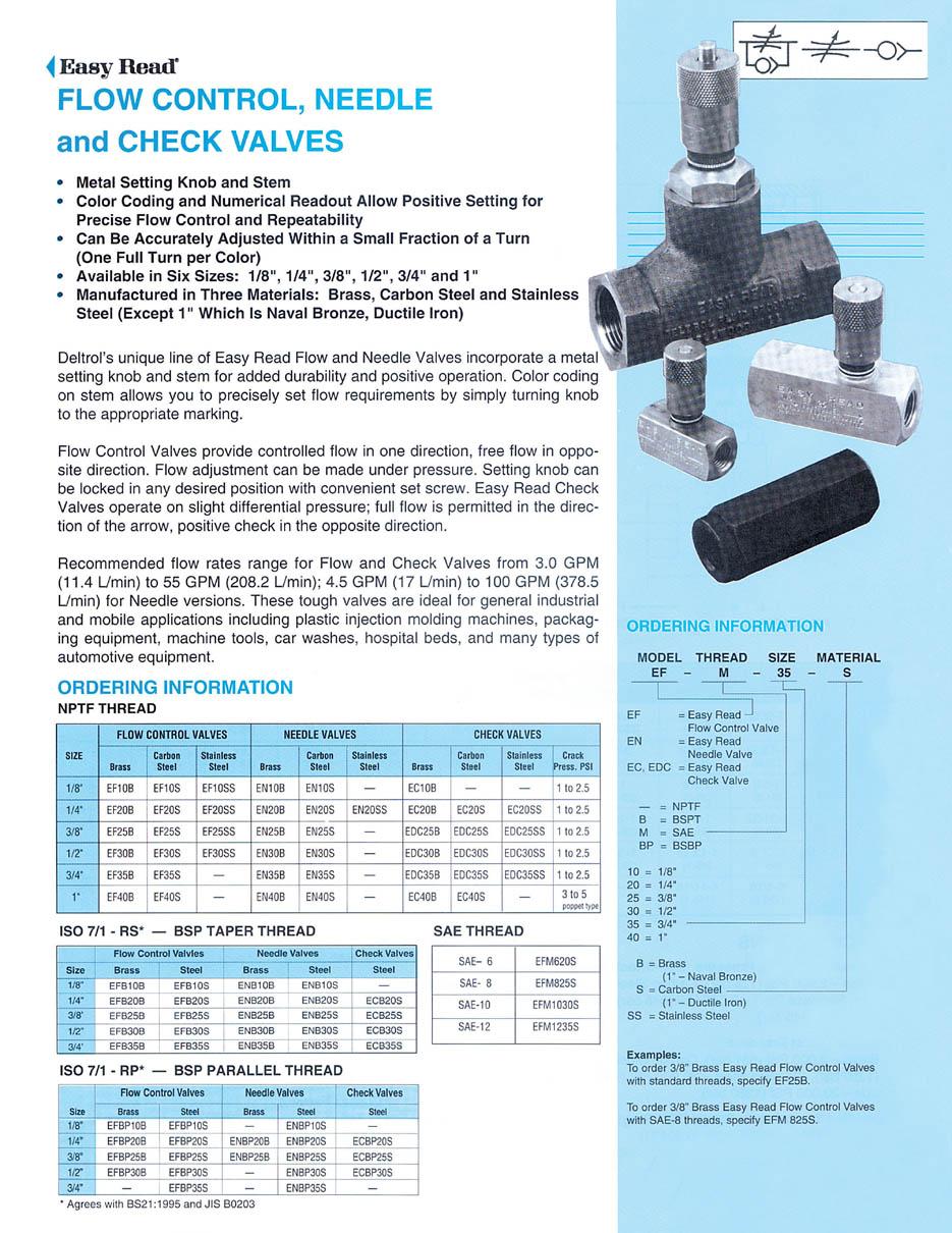
 Colorflow and Industrial Flow Control, Check, Gauge Control Catalog HY14-3300/US Colorflow and Fully guided poppets are used on Colorflow valves rather than the less durable ball-check type construction.
Series PD directly operated solenoid valves
 > Series PD solenoid valves CATALOGUE > Release 8.7 Series PD directly operated solenoid valves New /-way Normally Closed (NC) Note: all Series PD /-way solenoid valves are basically in DC. To operate
Catalog PowrFlowTM PVX Vane Pumps
 Catalog PowrFlowTM PVX Vane Pumps Your source for vane pumps for the most demanding applications. What Makes PowrFlow PVX Vane Pumps Your Best Buy? Continental Hydraulics PowrFlow PVX Vane Pumps deliver
Low Power. 1.4 W Low Power Solenoid Valves. Brass or Stainless Steel Bodies 1/4" to 1" NPT. Features
 .4 W Solenoid Valves Brass or Stainless Steel Bodies /4" to " NPT 4/ Features Moulded one-piece solenoid with highly efficient solenoid cartridge and special low wattage coil Designed for use in automation
Pressure Control Valves. General Description. Specifications. Ordering Information
 Catalog HY14-3000/US Technical Information Control Valves Series RCP General escription Series RCP in-line pressure control valves are chiefly used as remote control valves. They limit system pressure
Mobile Directional Valve. Product Catalog MDG for Mobile Equipment Flows to 60 I/min (15.8 USgpm)
") Mobile Directional Valve Product Catalog MDG for Mobile Equipment Flows to 60 I/min (15.8 USgpm) Table of Contents General Information...3 Model code Valve Section...4 Valve Assembly...5 Spool Data...6
Mobile Directional Valve Product Catalog MDG for Mobile Equipment Flows to 60 I/min (15.8 USgpm) Table of Contents General Information...3 Model code Valve Section...4 Valve Assembly...5 Spool Data...6
4/3-4/2 Directional valve elements LF1_1 (LC1F-Z)
") 4/3-4/2 Directional valve elements LF1_1 LC1F-Z) RE 18305-01 Edition: 02.2016 Replaces: 07.12 07.2012 Size 6 Series 00 Maximum operating pressure 310 bar 4500 psi) Maximum flow 35 l/min 9.25 gpm) Ports
4/3-4/2 Directional valve elements LF1_1 LC1F-Z) RE 18305-01 Edition: 02.2016 Replaces: 07.12 07.2012 Size 6 Series 00 Maximum operating pressure 310 bar 4500 psi) Maximum flow 35 l/min 9.25 gpm) Ports
Electrically Operated Pressure Reducing Cartridge, Size 16 Seated Pilot Stage, Spool Type Main Stage Series WDRVPA 5...
 Electrically Operated Pressure Reducing Cartridge, Size 16 Seated Pilot Stage, Spool Type Main Stage Series WDRVPA... 2 l/min, 3 bar Two pressure valve, HI / LO External pilot drain to port 3 Surface protection:
p max (see table of performances) Q max (see table of performances) bar Maximum flow rate from port P to A - B - T l/min
 Q max (see table of performances) bar Maximum flow rate from port P to A - B - T l/min") 41 400/117 ED E*P4 PILOT OPERATED DISTRIBUTOR SOLENOID OR HYDRAULIC (C*P4) CONTROLLED E4P4 CETOP P05 E4R4 ISO 4401-05 E5 ISO 4401-08 p max (see table of performances) Q max (see table of performances)
41 400/117 ED E*P4 PILOT OPERATED DISTRIBUTOR SOLENOID OR HYDRAULIC (C*P4) CONTROLLED E4P4 CETOP P05 E4R4 ISO 4401-05 E5 ISO 4401-08 p max (see table of performances) Q max (see table of performances)
D SERIES HYDRAULIC PUMP
 uk distributor for D SERIES HYDRAULIC PUMP quality products for mechanical & fluid power jbj Techniques Limited, www.jbj.co.uk Introduction to Concentric D Series Hydraulic Pumps Concentric offers one