MAINTENANCE TECHNIQUES and GEAR UNIT FAILURE MODES. MIKE FIELD DAVID BROWN GEAR INDUSTRIES Revision 1
|
|
|
- Emma Townsend
- 6 years ago
- Views:
Transcription

1 MAINTENANCE TECHNIQUES and GEAR UNIT FAILURE MODES MIKE FIELD DAVID BROWN GEAR INDUSTRIES Revision 1

2 Maintenance Regular maintenance saves money One hour per week of effort can save millions in lost production Train your staff to know what to look for
3 Typical problem areas Apart from the gears, other components within the unit give problems.
4 Blame the manufacturer It is a common misconception that when a unit fails it was incorrectly manufactured. Obviously, there are times when this is a correct conclusion, but independent surveys tell a slightly different story.

5
6
7 Correct installation If the unit is installed incorrectly, problems can be expected. Check for soft-foot or case twisting. Align the couplings. Fill the unit with the correct grade and amount of oil. Check all alarm interlocks are working and connected.

8 Common gear box problems Minor Oil leaks Ingress of dirt Water contamination Oil starvation Overheating Coupling misalignment Regular on site monitoring should eliminate these problems
9 Common gear box problems Major Lack of attention to the minor problems can result in the following typical major problems : Bearing failure Gear tooth damage Rust contamination Mechanical looseness Bearing bore wear Shaft damage

10 Common methods of monitoring gear units Human observation Overall vibration levels Spectral analysis Waveform analysis Oil analysis


11 Human observation The oldest and probably the most cost effective technique for assessing the condition of a gear unit is by using the three basic human skills of listening, looking and touching. Listen to the unit running, all knocks, rumbles or high pitch whistling should be noted and investigated. Look at the lubrication system. Is the pump working? Has the tank got lubricant in it? Do we have leaking seals or joints? Feel the gear case near the bearing housings. Can you keep you hand on the housing for a count of 10? For years, the mining industry has relied on these human skills and their importance cannot be underestimated.
12 Weekly routine maintenance - Enclosed gear units Check oil levels Check and clean breathers Check pressure, flow and temperature settings on lube systems - clean filters Check for oil leaks Check cooling fans are working Clean external surfaces of unit

13 Condition monitoring VIBRATION Overall levels Spectral Analysis OIL Wear Particle count % Water Viscosity & Additive package
14 Maintenance Vibration analysis using overall levels It is common practice on mechanical installations to use the level of mechanical vibration of the installation as an indication of the condition of the equipment. Various technical methods and equipment exist to undertake these analyses which are outside the scope of this presentation. However, for Gearbox Condition Monitoring, simple vibration measurements recording the velocity of the vibration can give excellent results. The simplest form involves recording the overall level of vibration in three planes (Horizontal, Vertical & Axial) on each bearing housing. The magnitude of these readings, recorded in mm/sec. RMS gives an early indication of a problem. Although various International Standards exist for allowable limits of such vibrations, none are specific to gear units. From experience, until the operator has a better understanding of his equipment, a limit of 5mm/sec RMS can be considered acceptable. Levels greater than this should result in more detailed investigation using Spectral Analysis methods
15 Maintenance Spectral analysis If the overall levels of vibration are greater than 5 mm/sec RMS, the analyst needs to identify the predominant frequency of this vibration. This can be done by making use of a Spectral Analyzer which breaks the vibration signal down into a series of discreet frequencies which make up the overall vibration. Once these frequencies are known, a simple comparison between them and the known forcing terms within the drive train will identify the cause of the problem.
16 Maintenance Common sources of vibration When making such comparisons, it is useful to remember that not only the gears contribute to the overall vibration of a mill. The most common sources of vibration are: - Rotational speeds of shafting Meshing frequency of the gears on the mill and the main drive gearbox Vibrational frequencies of the bearings within the drive train (BPFOR, BPFIR, BSF & the cage frequency) Alignment condition of the couplings Mechanical looseness between assembled components Out of balance or bent components
17 Acceptance criteria for vibration levels The magnitude of any discreet measured frequency should be within the following guidelines : Vibration measured in mm/sec. RMS Less than 2 mm/sec RMS Between 2 5 mm/sec RMS Greater than 5 mm/sec RMS EXCELLENT ACCEPTABLE Monitor for increasing tends UNACCEPTABLE Shutdown unit and eliminate cause of vibration
18 Maintenance - Checking vibration waveform It is a common misconception that Spectral Analysis can identify all sources of vibration. This is incorrect for a number of reasons, the most common ones being:- The lower frequency range of the accelerometer used for measurement is higher than the units lower rotational speeds. (accelerometer range 0.5 Hz, typical mill speed 0.2 Hz) A joint error, pitch error or broken tooth is expected to give a once per rev signal, which you would expect to be easily detected by Spectral Analysis. In fact these errors create a shock loading to the system which have the same effect as hitting the system with a hammer
19 Maintenance Checking vibration waveform Pitch errors, joint errors and broken teeth can however be detected by means of the real-time waveform traces.
20 Common failure modes of gear units We now have various methods of monitoring the condition of a unit whilst in operation. Once a problem is detected prompt action can avoid catastrophic failure. To insure corrective action is taken, the maintenance foreman needs to know what caused the problem.

21 Common failure modes of gear units Gear failure Mechanical looseness Bending fatigue of shafts Bearing bore wear Rust Bearing failure
 BENDING")
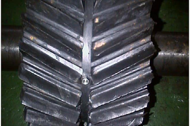
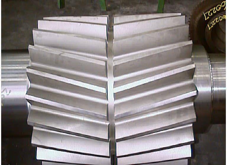
22 Common gear failure modes Although there are many different modes of failure of a gear, they can generally be classed into four categories: SCUFFING or SCORING ABRASIVE WEAR SURFACE FATIGUE (Pitting) BENDING FATIGUE

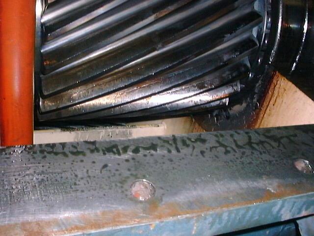
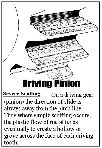
23
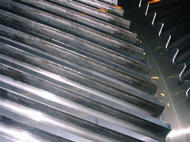
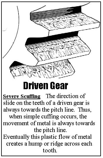
24
25 Abrasive wear Abrasion : When foreign material of an abrasive nature enters between the meshing teeth, the resulting lapping or grinding action may either polish the surfaces or scratch them. In either case this is abnormal wear. This type of wear is caused by ingress of abrasive material into the mesh. Typical abrasives are dirt, grit, mill slime & metal particles. Although similar in appearance to scuffing, the lines are usually less ragged and the tooth surface usually appears polished. The tooth flank along the pitch line is usually unmarked.
26

27 Surface fatigue Pitting Sub-surface cracking propagates to the surface until the piece falls out creating a pit.

28 Non-destructive, initial or pitch line pitting With this type of pitting, after a short operating period the pitting stops and the unit will operate satisfactory for its working life


29 Destructive pitting With this type of pitting, the contact stress generated during the meshing action is greater than the material endurance limit. The gear will continue to deteriorate.

30 Spalling Although similar to pitting, spalling is more commonly found on case hardened gears. Large pieces of the tooth surface break out.
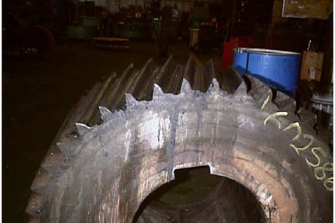
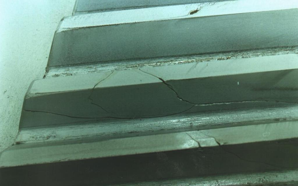
31 Bending Fatigue The most common form of tooth breakage is by fatigue. If a particular tooth is subjected to a higher load than it is designed to transmit, either by shock loading, misalignment or bad manufacture, the tooth is subjected to a higher bending moment as it passes through mesh.
32
33

34 Bending fatigue The most common form of bending fatigue which occurs on gears is known as a hump-back fatigue failure A crack occurring on the surface of the tooth will propagate along the line of maximum bending until it reaches the root zone. The point of maximum bending moment of a gear tooth is at the radius in the root of the tooth just below the working contact zone.
 The recommended fit for wheel / shaft assemblies in BS 1916 is H7/p6.")
35 Mechanical looseness A common problem with older gear boxes is looseness between the shaft and the wheel. Wheel / shaft assemblies are usually a combination of interference fit and keyways. The amount of interference fit to be used is specified by International Standards (BS 1916 : 1953) The recommended fit for wheel / shaft assemblies in BS 1916 is H7/p6. This allows for dismantling of the assembly for handing changes and gear rotation.

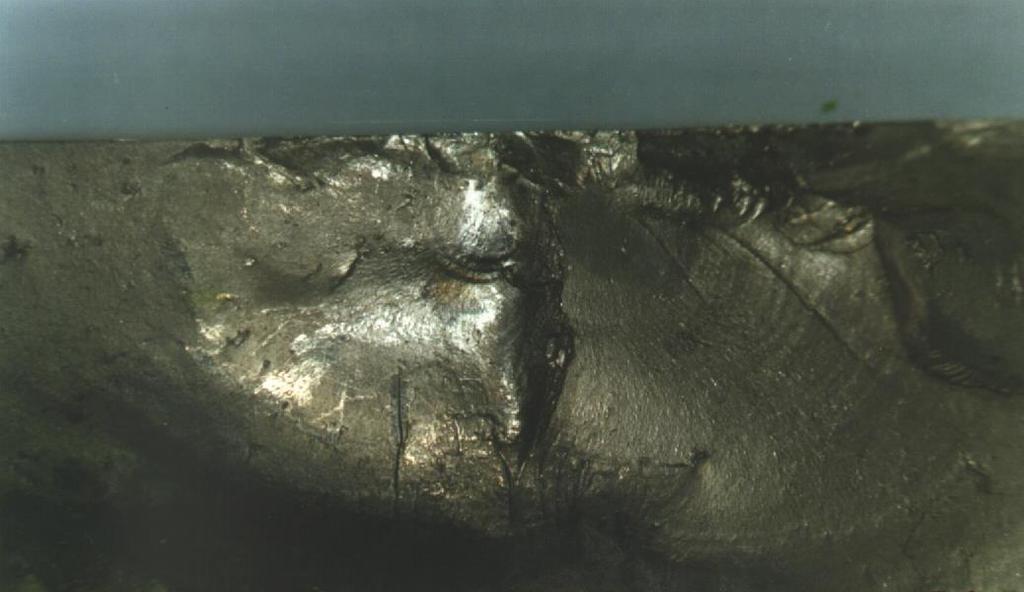
36 Mechanical looseness Note loss of material caused by fretting corrosion In some cases, when the components are manufactured at the extremes of their tolerance bands, this need for assembly / disassembly can result in insufficient interference to transmit the load

37 Mechanical looseness Note eye of fatigue With time, this results in fretting corrosion between the surfaces. This corrosion results in the wheel working loose on the shaft. If left uncorrected the corrosion accelerates until the wheel is no longer held in position on the shaft and an overload condition occurs on the keyway. Continued operation in this mode can result in keyway damage or shaft breakage.
38 Detecting looseness using spectral analysis Fortunately mechanical looseness can be detected using spectral analysis before catastrophic failure occurs. NOTE multiple harmonics of the pinion frequency detects mechanical looseness of the mating wheel assembly.
39 Bending fatigue of Shafts Input and output shafts of gear units are not only subjected to torsional stresses. If incorrectly installed or aligned the shafts can also be subjected to rotational bending stresses, with catastrophically effects. A very common mode of failure particularly on conveyor drives where the unit is shaft mounted via a rigid coupling is rotational bending fatigue.
40 Bending fatigue of Shafts Shaft mount assemblies are connected to the drive pulley of the conveyor by a rigid coupling. The alignment of this coupling is critical to the installation. Any angular mis-alignment between the coupling faces will cause the installation to oscillate at a frequency equal to the gear box output speed. This oscillation introduces an oscillating bending moment on the output shaft. The situation is commonly worsened by the erector forcing the base plate to align with the torque reaction point at the opposite end of the base plate. External bending moment applied to output shaft Baseplate forced to align with reaction pin
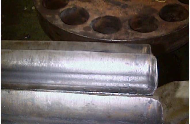
41 Bending fatigue of Shafts The introduction of this oscillating bending moment results in crack propagation normally emanating from changes in section in the shafting i.e. fillet radii, keyways, etc. With continued operation these cracks propagate radially inward toward the centre of the shaft until the shaft is no longer able to transmit the normal torque loads and failure due to a brittle fracture. Common origins of failure
42 Bending fatigue of Shafts Examination of the fracture surface after failure often reveals the cause of the failure 1. Moderate bending moment combined with high stress concentration. 2. Excessive bending moment with moderate stress concentration.

 or multiple (fillet")
43 Bending fatigue of Shafts This mode of failure results on the fracture site at right angles to the shaft axis with fatigue beach marks propagating inwards from a single (keyway) or multiple (fillet radii) origins.

44 Bearing bore creep Oscillating load causes the bearing to creep within its housing resulting in fretting corrosion. Commonly cause by coupling mis-alignment. Note early stages of fretting corrosion


45 Note rust damage at roller spacing
46 Bearing failure modes There are several modes of failure found on bearings, which can generally be categorised into three groups : False brinnelling Lubricant starvation Abrasive wear Fatigue Water contamination


47 False brinnelling The most common cause of false brinnelling in bearing is caused by shock loading or bad fitting practice by either the assembler or installer of the unit. If bearings or couplings are not correctly installed and force is used to position the bearing on its shaft, this force results in a depression onto the inner and outer raceways of the bearing caused by the bearing rollers. This can easily be identified by axial lines across the raceways at roller spacing.

48 False brinnelling These markings are effectively undulations across the raceways which cause localised overload as the rollers pass over the markings. With time, this localised overload causes fatigue damage to the raceways at roller spacing. Ultimately this will result in premature bearing failure.


49 Lubrication starvation This is by far the most common cause of bearing failure in gear units. Bearings require oil for two reasons, firstly to lubricate the bearing and secondly to cool the bearing. Inadequate cooling results in a differential expansion of inner race relative to the outer race. This reduces bearing clearance which further contributes to the heat input. Eventually the lubricate can no longer maintain an effective oil film and the bearing begins to seize. Once this occurs the failure is catastrophic.


50 Abrasive wear When foreign particles (grit, slime, coal dust, etc.) enters a gear unit, it mixes with the oil and forms an effective lapping paste. As the rollers pass across the bearing load zone this abrasive mixture causes excessive wear to all the rotating elements within the bearing (rollers, cages, raceways). This excessive wear results in excessive bearing clearances and misspacing of the rollers within the cage, which causes the rollers to slide across the raceways rather than rolling. This sliding action accelerates the rate of wear and also results in fatigue damage to the rolling elements.

51 Abrasive wear Although it is difficult to visually detect early stages of abrasive wear on rollers and raceways it can commonly be detected by inspection of the roller cage. Inspection of the cage at the ends of the rollers typically show early stages of abrasive wear. On split cage bearings, when the unit is stripped the contacting surfaces between each half cage shows severe scoring on the contacting surfaces.
52 Fatigue When Engineers talk about bearing life, they are talking of the number of operating hours a typical bearing can be subjected to a given load before the bearing commences to fail by the mechanisms of fatigue. Provided a bearing is correctly installed, lubricated, kept clean and not subjected to excessive overload or shock loading, the bearings can typically be expected to greatly exceed the designed life. Most fatigue failures therefore can be directly attributed to one or more of the above causes of failure.


53 Fatigue Typically the fatigue commences on the outer raceway of the bearing in the load zone. This can be expected since the outer raceway remains stationery and the same portion of its raceway is continually loaded. Inner raceways and rollers (by the fact that they are rotating) are less susceptible to localised overload. It must be recorded however that fatigue to rollers and inner raceways without damage to the outer raceway is not uncommon.

54 Water contamination Water entering the gear box either via the seals or breathers mixes with the lubricant and spreads throughout the unit. Once the unit is stopped and remains stationery for a period, the water separates from the lubricant and typically lies on the rollers and between the rollers and raceways. This results in rust corrosion of the bearing element which is effectively surface corrosion. Further operation of the bearing over these surface corrosion marks will result in the commencement of fatigue failure.
Failures of Rolling Bearings in Bar and Rod Mill
 Case Study Failures of Rolling Bearings in Bar and Rod Mill by Christo Iliev University of Zimbabwe, Dept. of Mechanical Engineering Harare, Zimbabwe INTRODUCTION Bar and rod mills can usually be found
Automotive manufacturing accelerometer applications
 Automotive manufacturing accelerometer applications Automotive manufacturing applications Spindle bearings Motor bearings Cooling tower motor and gearbox Stamping press motor and gearbox Paint booth air
Automotive manufacturing accelerometer applications
 Automotive manufacturing accelerometer applications The information contained in this document is the property of Wilcoxon Research and is proprietary and/or copyright material. This information and this
Fitting-removal and maintenance
 Fitting-removal and maintenance Fitting of bearings 136 General rules 136 Fitting principles 136 Hot fitting 137 Press fitting (or with anti-rebound hammer) 138 Adapter sleeves 139 Removal of bearings
REASONS YOUR BEARINGS WILL FAIL. Ritbearing CORPORATION
 12 REASONS YOUR BEARINGS WILL FAIL Ritbearing Things break. No matter what you do, there is always a chance that products you own will fail. The same holds true for bearings, but that doesn t mean that
Introduction. Lubrication Related Failures. Gear Couplings. Failure Analysis All Types (Page 1 of 7)
") All Types (Page 1 of 7) Introduction A gear coupling serves as a mechanical device which connects shafts of two separate machines and accommodates small amounts of shaft misalignment. Commercial gear couplings
All Types (Page 1 of 7) Introduction A gear coupling serves as a mechanical device which connects shafts of two separate machines and accommodates small amounts of shaft misalignment. Commercial gear couplings
Bearing Failure Analysis
 Bearing Failure Analysis The accurate diagnosis of a bearing failure is imperative to prevent repeated failures and their additional expenses. While performing failure analysis is commonly left to outside
Synchronous Belt Failure Analysis Guide
 Synchronous Belt Failure Analysis Guide Contents Part 1: Common Causes of Belt Failure Normal Belt Wear and Failure Belt Crimp Failures Shock Load Part 2: Improper Belt Installation Tension Introduction
Bearings. Rolling-contact Bearings
 Bearings A bearing is a mechanical element that limits relative motion to only the desired motion and at the same time it reduces the frictional resistance to the desired motion. Depending on the design
What is Wear? Abrasive wear
 What is Wear? Written by: Steffen D. Nyman, Education Coordinator, C.C.JENSEN A/S It is generally recognized that contamination of lubricating and hydraulic oils are the primary cause of wear and component
Sheet 1 Variable loading
 Sheet 1 Variable loading 1. Estimate S e for the following materials: a. AISI 1020 CD steel. b. AISI 1080 HR steel. c. 2024 T3 aluminum. d. AISI 4340 steel heat-treated to a tensile strength of 1700 MPa.
Improving predictive maintenance with oil condition monitoring.
 Improving predictive maintenance with oil condition monitoring. Contents 1. Introduction 2. The Big Five 3. Pros and cons 4. The perfect match? 5. Two is better than one 6. Gearboxes, for example 7. What
CLASSIFICATION OF ROLLING-ELEMENT BEARINGS
 CLASSIFICATION OF ROLLING-ELEMENT BEARINGS Ball bearings can operate at higher speed in comparison to roller bearings because they have lower friction. In particular, the balls have less viscous resistance
 DRUM BRAKE RIMS Periodic inspection of drum brake rims is necessary to determine indications of uneven or excessive wear. In general, brake rim failures other that regular wear are caused by brake linings
FUNCTION OF A BEARING
 Bearing FUNCTION OF A BEARING The main function of a rotating shaft is to transmit power from one end of the line to the other. It needs a good support to ensure stability and frictionless rotation. The
Gear Drives. A third gear added to the system will rotate in the same direction as the drive gear Equal diameters = Equal number of teeth = Same speed
 Gear Drive Systems Gear Drives Gear Drive: Synchronous mechanical drive that uses gears to transfer power Gear: A toothed wheel that meshes with other toothed wheels to transfer rotational power Pinion
ENGINEERING DATA. Fan Bearing Maintenance & Troubleshooting
 Information and Recommendations for the Engineer ENGINEERING DATA Fan Bearing Maintenance & Troubleshooting ED-1300 Aerovent TC Ventco Fiber-Aire Twin City Fan & Blower TC Axial Clarage Lubrication Proper
FAN ENGINEERING. Fan Bearing Maintenance & Troubleshooting
 FAN ENGINEERING Information and Recommendations for the Engineer Fan Bearing Maintenance & Troubleshooting FE-1300 Lubrication Proper lubrication and maintenance are essential for long bearing life. An
Care and Maintenance of Bearings
 For New Technology Network corporation R Care and Maintenance of Bearings Explanation of the Photos. These are microscopic photographs of peeling damage generated on the surface of a ball/roller bearing.
Chapter 11 Rolling Contact Bearings
 Chapter 11 Rolling Contact Bearings 1 2 Chapter Outline Bearing Types Bearing Life Bearing Load Life at Rated Reliability Bearing Survival: Reliability versus Life Relating Load, Life, and Reliability
Failure Analysis for Plain Bearings
 Failure Analysis for Plain Bearings William Strecker, Kingsbury Tags: bearing lubrication The textbook cases of distress modes are especially useful in diagnosing problems prior to the damage that occurs
Shifting gears: simplify your design with slewing ring bearings
 White Paper Shifting gears: simplify your design with slewing ring bearings Scott Hansen, VP, Manufacturing Planning, Kaydon Bearings, an SKF Group company A slewing ring bearing has rolling elements designed
PO Box 645, Stockton, Missouri, FAX superiorgearbox.com
 I000-7000-D0447-A 4/7/05 1 SAFETY PRECAUTIONS CAUTION Please read this entire document prior to operating the gear drive. Gear drive failure and / or injury to operators may be caused by improper installation,
Troubleshooting Power Transmission Couplings
 Troubleshooting Power Transmission Couplings Introduction Power transmission couplings are used to connect two shafts that turn in the same direction on the same centerline. There are three principle types
BLISS PELLET MILL 200
 BLISS PELLET MILL 200 TORQUE GUIDE 200 PELLET MILL The Brake B-loc 112 series torque 225nm The Brake b-loc 115 series torque 142nm Mainshaft nut Drive belt 250 mm Drive belt 340mm Roll settings Gap for
Detection of Fault in Gear Box System using Vibration Analysis Method
 Research Article International Journal of Current Engineering and Technology E-ISSN 2277 4106, P-ISSN 2347-5161 2014 INPRESSCO, All Rights Reserved Available at http://inpressco.com/category/ijcet Detection
TRANSLATION (OR LINEAR)
") 5) Load Bearing Mechanisms Load bearing mechanisms are the structural backbone of any linear / rotary motion system, and are a critical consideration. This section will introduce most of the more common
5) Load Bearing Mechanisms Load bearing mechanisms are the structural backbone of any linear / rotary motion system, and are a critical consideration. This section will introduce most of the more common
DIAMOND ROLLER CHAIN. For Agricultural and Construction Equipment
 DIAMOND ROLLER CHAIN For Agricultural and Construction Equipment FABRICATION While roller chain would appear to be a simple product, the number of components in a ten foot section of 40 pitch chain totals
TIMING AND ACCESSORY Ranges. Diagnostic Expert Analysis & Recommendations
 Diagnostic Expert Analysis & Recommendations MAJOR CAUSES OF TIMING BELT FAILURES: 1 Uneven breakage 2 A clean break 3 Detached or separation of the belt teeth 4 Ripped teeth 5 Split teeth 6 Loss of teeth
TECHNICAL INFORMATION
 General Nomenclature Spherical Roller Bearings The spherical roller bearing is a combination radial and thrust bearing designed for taking misalignment under load When loads are heavy, alignment of housings
Application Note. Case study Early fault detection of unique pump bearing faults at a major US refinery
 Application Note Case study Early fault detection of unique pump bearing faults at a major US refinery Application Note Case study Early fault detection of unique pump bearing faults at a major US refinery
PO Box 645, Stockton, Missouri, FAX superiorgearbox.com W D0446-A 4/1/05 1
 W000-7000-D0446-A 4/1/05 1 SAFETY PRECAUTIONS CAUTION Please read this entire document prior to operating the gear drive. Gear drive failure and / or injury to operators may be caused by improper installation,
Engine Bearing Failure Analysis By Clevite 1965
 Engine Bearing Failure Analysis By Clevite 1965 RECOMMENDED BEARING INSTALLATION TOLERANCES CRANKCASE TOLERANCES Finish of main bores 80 micro inch or better. Bore Tolerance.001 " up to 10" bore,.002"
BEARING MAINTENANCE. Mounting. Lubrication. Dismounting
 BEARING MAINTENANCE Mounting. Lubrication. Dismounting 1 IMPORTANCE OF PROPER MOUNTING PROCEDURES Ensure safety Simplicity and speed the process Using full bearing capabilities Get the longest possible
Front Wheel Drive Notes
 Front Wheel Drive Notes Drive Axle Components Outer CV-joint Allows wheels to steer while axle is rotating Inner CV-joint Allows for suspension changes while axle is rotating Axle shaft Transmits power
Warranty Approval. Visual Inspection of Starters & Alternators
 Warranty Approval Visual Inspection of & Alternators Is it Genuine Delco Remy? 37MT, 41MT & 42MT Older Delco Remy stamp Current ink stamping 38MT & 39MT Current stamping Current reman label Stamped customer
GatesFacts Technical Information Library Gates Compass Power Transmission CD-ROM version 1.2 The Gates Rubber Company Denver, Colorado USA
 MAKING THE RIGHT SHAFT CONNECTIONS Daniel Schwartz & Gary Porter Power Transmission Design August, 1996 Securing a belt pulley to a drive shaft often seems like such a routine task, that engineers and
MAIN SHAFT SUPPORT FOR WIND TURBINE WITH A FIXED AND FLOATING BEARING CONFIGURATION
 Technical Paper MAIN SHAFT SUPPORT FOR WIND TURBINE WITH A FIXED AND FLOATING BEARING CONFIGURATION Tapered Double Inner Row Bearing Vs. Spherical Roller Bearing On The Fixed Position Laurentiu Ionescu,
Table of Contents. 4. Before a New Turbocharger is Installed
 Table of Contents 1. Turbocharger Overview ------------------------------------------------------------------ 1.1. Definition -----------------------------------------------------------------------------
Mounted bearing installation and best practices for the grain industry
 CONVEY 18 / 7-25-20 18 Mounted bearing installation and best practices for the grain industry Marc Mondi, Territory Manager ABB/Dodge Agenda OSHA standards related to grain handling bearings Bearing myths
Bearing Handling. 15. Bearing Handling Bearing storage Installation
 15. Bearing Handling Bearings are precision parts and, in order to preserve their accuracy and reliability, care must be exercised in their handling. In particular, bearing cleanliness must be maintained,
CYLINDRICAL ROLLER BEARING CATALOG TIMKEN THRUST AND PLAIN BEARINGS CATALOG
 CYLINDRICL ROLLER BERING CTLOG TIMKEN THRUST ND PLIN BERINGS CTLOG Spherical Plain Bearings SPHERICL PLIN Overview: Timken s spherical plain bearings consist of a spherically ground inner ring housed in
Ch# 11. Rolling Contact Bearings 28/06/1438. Rolling Contact Bearings. Bearing specialist consider matters such as
 Ch# 11 Rolling Contact Bearings The terms rolling-contact bearings, antifriction bearings, and rolling bearings are all used to describe the class of bearing in which the main load is transferred through
Pump Coupling & Motor bearing damage detection using Condition Monitoring at DTPS
 Journal of Physics: Conference Series Pump Coupling & Motor bearing damage detection using Condition Monitoring at DTPS To cite this article: H M Bari et al 2012 J. Phys.: Conf. Ser. 364 012022 View the
Expand your vibration program to new heights.
 Expand your vibration program to new heights. Cooling Tower Monitoring Wireless Vibration Monitoring for Motor and Gearbox Combination Monitoring your cooling towers presents a unique set of challenges
MAXIMIZING PUMP RELIABILITY THROUGH PRECISION LUBRICATION
 1 MAXIMIZING PUMP RELIABILITY THROUGH PRECISION LUBRICATION INTRODUCTION More so than any other industry, the hydrocarbon processing industry relies on rotating equipment to deliver results. From pumps
Installation Procedures
 For the precision ball and roller bearings supplied by MRC Bearings, skill and cleanliness while handling, mounting and dismounting are necessary to ensure satisfactory bearing performance. As precision
Roller Screw Actuators: Benefits, Selection and Maintenance
 Roller Screw Actuators: Benefits, Selection and Maintenance Last Printed June 10, 2010; Author: Gary Shelton, Principal Design Engineer, Exlar Corp., Chanhassen, Minn. The choice of hydraulic/pneumatic
Trends Regarding Rolling Bearings for Steering Systems
 Trends Regarding Rolling Bearings for Steering Systems M. TANIYAMA * *Automotive Engineering Center, Automotive Bearing Engineering Department Many bearings are used in the columns, gears and pumps of
Power transmission. Components used to transmit power: gears, belt, clutch and brakes. Gear (Stresses) act on the tooth Lewis formula and AGMA
 act on the tooth Lewis formula and AGMA") 1 Power transmission Components used to transmit power: gears, belt, clutch and brakes. Failure Types Gear (Stresses) Bending: resulted from bending stress. t act on the tooth Lewis formula and AGMA Pitting:
1 Power transmission Components used to transmit power: gears, belt, clutch and brakes. Failure Types Gear (Stresses) Bending: resulted from bending stress. t act on the tooth Lewis formula and AGMA Pitting:
Mechanical Actuators
 Mechanical Actuators Translating Machine Screw Actuators 100-Ton, 150-Ton & 250-Ton Capacity Installation, Operation & Maintenance Instructions Publication Part No. SK-2389-100 CAUTION This manual contains
SERIES PC INSTRUCTION AND OPERATION MANUAL
 MEGGA SERIES PC INSTRUCTION AND OPERATION MANUAL Models PCT and PCF Close-coupled and frame-mounted single-stage horizontal end-suction pumps. WARNING: Read this manual before installing or operating this
Chapter 7. Shafts and Shaft Components
 Chapter 7 Shafts and Shaft Components 2 Chapter Outline Introduction Shaft Materials Shaft Layout Shaft Design for Stress Deflection Considerations Critical Speeds for Shafts Miscellaneous Shaft Components
Steering and Suspension
 The Steering and Suspension system is engineered to allow the vehicle to turn and absorb road irregularities. The suspension is comprised of springs, suspension arms or links and shock dampers. These components
114 NOSE SEIKO CO.,LTD NOSE SEIKO CO.,LTD
 114 NOSE SEIKO CO.,LTD NOSE SEIKO CO.,LTD 115 and Part Code Applicable axis diameter Feature Part Code 5 ~ 3 General purpose cam follower with screwdriver groove on the stud head. Available with stainless
CHAPTER 5 FAILURE ANALYSIS OF MAIN BEARING
 93 CHAPTER 5 FAILURE ANALYSIS OF MAIN BEARING 5. 1 BEARING LAYOUT The two main bearings are used in the crankshaft assembly, one bearing is at the drive end side of the crankshaft and another bearing is
ME 343: Mechanical Design-3
 What are bearings? ME 343: Mechanical Design-3 Bearings Dr. Aly Mousaad Aly Department of Mechanical Engineering Faculty of Engineering, Alexandria University Machines with moving parts must have some
ME 343: Mechanical Design-3. Department of Mechanical Engineering Faculty of Engineering, Alexandria University
 ME 343: Mechanical Design-3 Bearings Dr Aly Mousaad Aly Dr. Aly Mousaad Aly Department of Mechanical Engineering Faculty of Engineering, Alexandria University What are bearings? Machines with moving parts
MRC Bearing Solutions for the Hydrocarbon Processing Industry
 MRC Bearing Solutions for the Hydrocarbon Processing Industry M230-710 February 1996 Table of Contents Selection of the Proper Bearing Solution.................... 1 Relative Bearing Performance Characteristics................
Parts made by people who race and know what it is about
 RACING TRANSMISSIONS / 840 SERIES The 840 series has been one of the best options for front engine-rear wheel drive racing cars with4/6 cylinder engines since 1975; formerly, with the TC models, and at
TOUGH AND LONG LIFE (TL) SERIES SPHERICAL ROLLER BEARINGS
 SERIES SPHERICAL ROLLER BEARINGS") TOUGH AND LONG LIFE (TL) SERIES SPHERICAL ROLLER BEARINGS TOUGH PERFORMANCE IN HIGH TEMPERATURES. High temperature processing and manufacturing environments, such as those in the dryer section of paper
TOUGH AND LONG LIFE (TL) SERIES SPHERICAL ROLLER BEARINGS TOUGH PERFORMANCE IN HIGH TEMPERATURES. High temperature processing and manufacturing environments, such as those in the dryer section of paper
SNR - Industry. The SNR Expert Diagnosis: Analysis and Recommendations for Optimizing Bearing Life. INDUSTRY
 The SNR Expert Diagnosis: Analysis and Recommendations for Optimizing Bearing Life. SNR - Industry INDUSTRY How to recognize failures? Appearance of suspect bearings These pictures are representative of
Vibration product training Gearbox tutorial
 Vibration product training May 2012 Introduction Transducers come in two basic types Contact - which measure the absolute movement of the casing Noncontact - which measure the relative movement of the
Impact of Bearing Vibration on yarn quality in Ring Frame
 IOSR Journal of Polymer and Textile Engineering (IOSR-JPTE) e-issn: 2348-019X, p-issn: 2348-0181, Volume 2, Issue 3 (May - Jun. 2015), PP 50-59 www.iosrjournals.org Impact of Bearing Vibration on yarn
Disassembly Procedures and Analysis
 ÂÂ Terms and Definitions Special Engine Tools and Their Functions Precision Instruments and Their Functions Disassembly Procedures and Analysis Disconnecting Accessory Components Methods for Cleaning Engine
THE POSSIBILITIES OF EARLY FAULT DETECTION OF ENGINES
 Journal of KONES Powertrain and Transport, Vol. 20, No. 4 2013 THE POSSIBILITIES OF EARLY FAULT DETECTION OF ENGINES Jan Filipczyk Silesian University of Technology, Faculty of Transport Krasinskiego Street
A Grinding Solution. By John Donkers
 A Grinding Solution A customer had a problem using their existing gears in a new application. Ontario Drive & Gear provided the solution. Here s how they did it. By John Donkers A company approached Ontario
MAINTENANCE AND REPAIR INSTRUCTIONS
 MAINTENANCE AND REPAIR INSTRUCTIONS TYPE TH PUMPS Peerless Pump Company Indianapolis IN, 46207-7026 4849357 TABLE OF CONTENTS Maintenance Page 1 & 2 Disassembly Page 5 & 6 Impeller Clearance 3 Reassembly
Module 1: Introduction to Drive Trains
 Introduction ÂÂ Basic Components of a Drive Train Operation of a Drive Train Working Applications Types of Drives Types of Gears Formula for Calculating Gear Ratio Determining Gear Rotation Introduction
DIAMOND CHAIN COMPANY INC. Maintenance Guide
 Maintenance Guide 2006 BULLETIN 1067 TABLE OF CONTENTS ORDERING INFORMATION 3 INSTALLATION 4 LUBRICATION 5 INSPECTIONS 6 ELONGATION LIMITS 7 WHAT IS CHAIN WEAR? Did you know Chain does not STRETCH? Chain
PUMP BEARING TRAINING
 PUMP BEARING TRAINING PRESENTED BY AARON DODD NSK AMERICAS JUNE 24, 2015 Unless otherwise specifically noted, the competitive information contained in this presentation is gathered from legally permissible
1. FAILURE DUE TO DEFECTIVE BEARING SEATS ON SHAFTS AND IN HOUSINGS
 Source Application Manual SAM Chapter 630-44 Section 22 From a Publication by SKF Industries, Inc. BEARING FAILURES AND THEIR CAUSES INTRODUCTION All too frequently the Refrigeration Service Engineer finds
Objective. Outcomes of the Training
 Purpose, Use & Care of Roller Bearings. Training for Plant and Equipment Operators, Maintainers and, Technicians. Objective This training teaches users and maintainers of roller bearings why they are used,
Amarillo PUMP DRIVES (250 HP THROUGH 350 HP) INSTRUCTIONS FOR REPAIRING MODELS 250, 300, and 350
 INSTRUCTIONS FOR REPAIRING MODELS 250, 300, and 350") Amarillo PUMP DRIVES (250 HP THROUGH 350 HP) INSTRUCTIONS FOR REPAIRING MODELS 250, 300, and 350 Amarillo Right Angle Pump Drives, if properly installed and maintained, should provide years of service
Amarillo PUMP DRIVES (250 HP THROUGH 350 HP) INSTRUCTIONS FOR REPAIRING MODELS 250, 300, and 350 Amarillo Right Angle Pump Drives, if properly installed and maintained, should provide years of service
Heavy-Duty Rod Ends - Male with integral spherical plain bearing
 Heavy-Duty Rod Ends - Male with integral spherical plain bearing 65700 Order No. Thread (hand) d 1 l 1 d 2 d 3 d 4 l 2 l 3 X g H7 65700.W0005 Right 5 33 M 5 11,11 18 20 9 14 65700.W0006 Right 6 36 M 6
Power Transmission. Installation and Operating Instructions for Integrated Freewheels FXRV and FXRT. E e.
 Power Transmission Installation and Operating Instructions for Schaberweg 30-34 Telephone +49 6172 275-0 61348 Bad Homburg Telefax +49 6172 275-275 Germany www.ringspann.com mailbox@ringspann.com Issue:
Kaydon white paper. The importance of properly mounting thin section bearings. an SKF Group brand. by Rob Roos, Senior Product Engineer
 The importance of properly mounting thin section by Rob Roos, Senior Product Engineer an SKF Group brand Figure 1 Radial Load Reversing Thrust Overturning Moment Thin section ball have a much thinner cross-section
BEARING HANDLING AND MAINTENANCE
 AND MAINTENANCE AND MAINTENANCE AND MAINTENANCE Part B AND MAINTENANCE 1. B 005 2. DAMAGE AND MEASURES (Bearing Doctor) B 021 B 003 1. 1.1 Precautions for Proper Handling of Bearings B 006 1.2 Bearing
Module 6: Air Foundation Brakes
 Air Brakes Terms and Definitions Basic Components That Make Up Air Foundation Brakes Types of Air Foundation Brakes Parts of a Cam Foundation Brake Parts of a Wedge Foundation Brake Parts of a Disc Foundation
Monitoring Water in Lube Oil
 Monitoring Water in Lube Oil Page 1/10 Water in Lube Oil Water is vital to life on earth, but in some contexts water is unwanted and can cause severe damage. On the other hand oil is also a important part
Shaft Mounted Speed Reducers
 s Metric Range Features The Challenge SMSR stands tall amongst the crowd. Packed full of attention to detail, the Challenge SMSR delivers performance in the harshest of applications. Shaft mounted drives
SPLIT MOUNTED HT750/H1000/NT600 INSTALLATION MANUAL
 9/26/16 HIGH TEMP BEARINGS SPLIT MOUNTED HT750/H1000/NT600 INSTALLATION MANUAL www.hightempbearings.com HTB Split Mounted HT750/1000/NT600 Sleeve Bearings Installation HTB Manual REV A REV A Split Mounted
IDENTIFYING DISC COUPLING FAILURES COUPLING FUNDAMENTALS
 IDENTIFYING DISC COUPLING FAILURES While couplings are designed for infinite life, they must be operated within their intended design limits in order to achieve optimal performance. Due to installation
PREDICTING BEARING FAILURES AND MEASURING LUBRICATION FILM THICKNESS IN YOUR PLANTS ROTATING EQUIPMENT
 PREDICTING BEARING FAILURES AND MEASURING LUBRICATION FILM THICKNESS IN YOUR PLANTS ROTATING EQUIPMENT Bob Kappa SPM Instrument Inc. 780 Bailey Hill Road, Suite 3 Eugene, OR 97402 ABSTRACT Typically there
DESIGN CONSIDERATIONS FOR ROTATING UNIONS SEALING TECHNOLOGIES
 DESIGN CONSIDERATIONS FOR ROTATING UNIONS SEALING TECHNOLOGIES Rotating unions convey fluid from a stationary supply line to equipment or a rotating tool. They are critical elements in a variety of applications
TROUBLESHOOTING SPECIAL TOOL ASSEMBLY AND ADJUSTMENT
 1 INDEX Models FD, FE, FF and SG REAR AXLE 10-1 10-108E-07 CHAPTER 10 REAR AXLE Models FD, FE, FF and SG TROUBLESHOOTING...10-2 10 SPECIAL TOOL...10-3 WHEEL HUB AND RELATED PARTS DISASSEMBLY...10-7 INSPECTION...10-9
2002 F-Super Duty /Excursion Workshop Manual
 Page 1 of 5 SECTION 205-02D: Rear Drive Axle/Differential Ford 10.50-Inch Ring Gear 2002 F-Super Duty 250-550/Excursion Workshop Manual DIAGNOSIS AND TESTING Procedure revision date: 02/02/2005 Rear Drive
If I have seen farther it is by standing on the shoulders of Giants. Isaac Newton
 HALF SHAFTS If I have seen farther it is by standing on the shoulders of Giants. Isaac Newton 102 Throughout the years we have been fortunate to have many of the world s best car designers, panel beaters,
CONTENT. 1. Syllabus 2. Introduction 3. Shaft 4. Coupling. Rigid coupling. Flange coupling. Sleeve (or) muff coupling Split muff coupling
 muff coupling Split muff coupling") UNIT II 1. Syllabus 2. Introduction 3. Shaft 4. Coupling Rigid coupling CONTENT Flange coupling Protected flange coupling Unprotected flange coupling Marine type flange coupling Sleeve (or) muff coupling
UNIT II 1. Syllabus 2. Introduction 3. Shaft 4. Coupling Rigid coupling CONTENT Flange coupling Protected flange coupling Unprotected flange coupling Marine type flange coupling Sleeve (or) muff coupling
Randy Recommends... If your bike has chain drive, here are some things you should know.
 Chains part 1: Sizing Motorcycle drive chains are made up of alternating internal links and external links, connected by pins. The internal links consist of two plates connected to each other through two
Chapter 11 Rolling Contact Bearings
 Chapter 11 Rolling Contact Bearings 1 2 Chapter Outline 3 Overview The term rolling bearing is used to describe class of bearing in which the main load is transferred through elements in rolling contact
Get out the surgical gloves when working around the most fragile of bearings.
 Published on Machine Design (http://machinedesign.com) Miniature ball bearings: Handle with care by Lawrence Kren Created 10/23/2003-03:00 Get out the surgical gloves when working around the most fragile
SKF Explorer spherical roller bearings Optimized for superior field performance
 SKF Explorer spherical roller bearings Optimized for superior field performance Continuous improvement to optimize The timeline below illustrates SKF milestones in the development of self-aligning bearings.
ANZSASI 2000 CHRISTCHURCH ENGINEERING ANALYSIS. Vlas Otevrel
 ENGINEERING ANALYSIS Vlas Otevrel 1 Garrett TPE 331 engine turbine failure The engine was fitted to a Metro II aircraft engaged in a freight run. Just after the top of descent, some 20 nm from destination,
Comparison Chart. extremely difficult. Finally, separated components can rarely be re-used.
 JAN 2014 Traditional Connections Why Go Keyless Keyed Bushing Systems Both QD and Taper-Lock bushing and weld-on hub systems are popular component mounting technologies. Yet both are ultimately keyed connections
13. DRIVE TRAIN 13-0 DRIVE TRAIN MXU 500
 13 DRIVE TRAIN SERVICE INFORMATION------------------------------------------------ 13-2 TROUBLESHOOTING----------------------------------------------------- 13-2 FRONT DRIVE SHAFT REMOVAL/INSPECTION/ INSTALLATION
1 Mounting V-belt drive (motor pulley, fly wheel, V-belts and guard)
") Mounting V-belt drive (motor pulley, fly wheel, V-belts and guard) General safety instructions, requirements and procedures 1 Mounting V-belt drive (motor pulley, fly wheel, V-belts and guard) 1.1 General
Mounting V-belt drive (motor pulley, fly wheel, V-belts and guard) General safety instructions, requirements and procedures 1 Mounting V-belt drive (motor pulley, fly wheel, V-belts and guard) 1.1 General
Chapter 11. Keys, Couplings and Seals. Keys. Parallel Keys
 Chapter 11 Keys, Couplings and Seals Material taken for Keys A key is a machinery component that provides a torque transmitting link between two power-transmitting elements. The most common types of keys
BOTTOM END SERVICE TOOLS SERVICE PRODUCTS ENGINE, CVT AND GEARBOX Subsection 10 (BOTTOM END)
") BOTTOM END SERVICE TOOLS Description Part Number Page CRANKCASE SUPPORT MAG/PTO... 529 036 031... 151 CRANKSHAFT LOCKING BOLT... 529 035 617... 154 DRIVE SHAFT OIL SEAL INSTALLER... 529 036 028... 143
BOTTOM END SERVICE TOOLS Description Part Number Page CRANKCASE SUPPORT MAG/PTO... 529 036 031... 151 CRANKSHAFT LOCKING BOLT... 529 035 617... 154 DRIVE SHAFT OIL SEAL INSTALLER... 529 036 028... 143
REMY TECHNICAL SERVICE BULLETIN
 June 2018 REMY TECHNICAL SERVICE BULLETIN Remy Power Products is continuously adding technical training and technical information. We welcome suggestions. If there is something technical you would like