P-BarSeries BOL AOL. We COOL what you POWER. Plate & Bar Aluminum. Standard. Air-Oil Coolers. Standard. Models. Now featuring Brushless DC Fans
|
|
|
- Jemimah Fisher
- 6 years ago
- Views:
Transcription


1 2014 Plate & Bar Aluminum Standard Air-Oil Coolers P-BarSeries We COOL what you POWER thermaltransfer.com Standard Models MA Now featuring Brushless DC Fans BOL Now featuring two relief bypass options AOL


 n Standard SAE ports NPT and BSPP ports available n")


2 Mobile MA NEW! option MA heat transfer units provide rugged high performance for demanding mobile equipment oil cooling applications. Select from our broad line of standard units to satisfy your specific requirements. All feature proven brazed aluminum P-Bar (plate and bar) core technology, engineered with an aggressive turbulator that produces ultra-high heat transfer. Choose MA standard units with flow rates ranging from 2gpm to 150gpm for extreme oil cooling performance. Now available with axial fans equipped with Brushless DC motors! When combined with our highest performing Bar & Plate aluminum core, the result is outstanding airside performance while utilizing the benefits of a brushless electric motor. Features n Plate and Bar brazed aluminum core n Rugged, lightweight, and compact n Brushless DC fan motor now available n Provides the best heat transfer per given envelope size while minimizing pressure drop n Air-side fin design minimizes fouling and static pressure ensuring long-term, reliable performance n Fans compliant with IP 68 (Brushed) and IP6K9K (Brushless) with fully sealed motors n Welded Aluminum fittings/ports and manifolds ensure structural integrity n 30/60 psi Bypass available (MAR) n Standard SAE ports NPT and BSPP ports available n Customized units are available to meet your specific performance requirements Without Bypass With Bypass Materials Ratings Fluid Compatibility n Core Brazed Aluminum Bar and Plate n Tanks 5052 Aluminum n Nose Bar & Little Bar 3003-H Aluminum n Air Fin, Plate, Turbulator & End Plate 3003-O Aluminum n Connections Aluminum n Core Mounting Brackets Brazed Aluminum n Maximum Operating Pressure 250 psi (17 BAR) n Maximum Operating Temperature 300 F (150 C) n Petroleum/mineral oils n Oil/water emulsion n Water/ethylene glycol Dimension Range HEIGHT WIDTH DEPTH* Model Inches mm Inches mm Inches mm MA MA MA MA MA MA MA MA MA *Depth is for standard DC fans only. Width Depth Height Width Depth Height


3 Brushless DC Fan TTP now offers axial fans equipped with Brushless DC electric motors for Oil Cooling. These fans are a featured option on P-Bar Series MA standard catalog Oil Coolers. Brushless motors are fully reversible and offer benefits for extended life including low current draw on start up, custom fan speed control and lower ambient noise. Axial Fan Efficiency The air mover is a high end performance fan blade, designed for optimal fluid dynamic performance. When combined with our highest performing Bar and Plate aluminum core, the result is outstanding airside performance while using minimal electrical load. Brushless DC Electric Motor Efficiency Motors can achieve remarkable electrical efficiency greater than 82% making them among the most efficient motors in the SBL300 Series through SLB500 Series power range. Features n Cutting edge motor/fan blade technology n High energy ferrite magnets and state-of-the-art sine wave sensor-less drive n Fans compliant with IP68/IP6K9K with fully sealed motors. Operates in challenging environments. n PWM and analog input for continuous adjustment of fan speed n Electronic controls with on-board diagnostics n EMC directives: 2006/28/EC n Spark free n Protection: Overtemperature Overcurrent Mechanical overload Locked rotor Load dump Overvoltage Undervoltage Active reverse polarity protection n Low noise, vibration and harshness - noise dampers on shroud n Battery compensation system n Low inertia inner rotor design n Low weight motor n Higher ambient working temperature n Speed control if tied to a direct interface to an external temperature sensor n High resistance to vibration and mechanical stress n Integrated finger guards Performance n Reduce maximum coolant temperature n Eliminate engine power cut-back n Full reversibility keeps oil cooler clean n Pusher, puller, 12V or 24V configurations to meet any application need n Applying Distributed Cooling Principle increases available engine horsepower Longevity n Power and control electronics are integrated and separated within the sealed motor to ensure operation at lower surface temperature levels. This design ensures long life and increased product reliability. n TTP Brushless electric motors have a double-sealed ball bearing design, guaranteeing product life of more than 30,000 hours in most conditions. Off Road Ready Brushless motor fan for all conditions. Protection against mud, sand, dust, water, saline fog and chemicals, coupled with an Oil Cooler core that is easy to clean and service, equals a lasting solution! Motor Specifications Typical Continuous Operation Operating Temperature Range: F (148 C) Storage Temperature Range: F (125 C) Lifetime: over hrs (depending on specific mission profile) Operating Voltage Range: 8 16V and 16 32V Stand-By Current: < 0.1 Ma SBLl W Electrical 212 F (100 C) ambient temperature 250W Electrical 230 F (110 C) ambient temperature SBL500P (coming soon for HOC assemblies) 500W Electrical 212 F (100 C) ambient temperature 450W Electrical 230 F (110 C) ambient temperature The maximum electrical input power depends on the maximum operating temperature of the fan module and can be customized accordingly. 3
4 Dimensions - Fan/Core MA-3.75 (19) 1.00 (25) MA-3.5 O-RING.75 #12 SAE (19) 3/4 NPT 3/4 BSPP 1.00 (25) O-RING #12 SAE 3/4 NPT 3/4 BSPP.89 (22.61) 1.77 (44.96) 1.77 (44.96) 12V DC FAN/MOTOR.89 (22.61) ASSEMBLY MA-4 AIR FLOW 8.25 (210) AIR FLOW FAN/ MOTOR ASSEMBLY (317) 1.18 (30) 12V DC FAN/MOTOR 5.89 (150) ASSEMBLY 6.26 (159) CONSULT FACTORY 2.63 (67) 3.66 (93) 3.54 (90) 3.54 (90) 5.29 (134) 7.64 (194.06) 6.26 (159) AIR FLOW (135) (229.11) AIR FLOW 4.47 (114) 5.33 (135) 5.33 (135) 6.14 (156).18 (4.57) TYP 2.03 (51.56) A A H G.39 (10) 2.99 (76) 5.98 (152) (850) #16 SAE OPTIONAL & AIR FLOW.39 (10).44 X.75 (11 x 19) SLOT 4 PLACES.37 (9) HOLE 4 PLACES MA-232 MA-12, MA-18, MA-32 JG AIR FLOWREVERSIBLE BYPASS 1.31 (33).12 (3) TYP AIR FLOW.44 X.75 SLOT (11) x 19) 8 PLACES OPPOSITE SIDE (797) 30/60 ASSEMBLY 1.31 (33).44 X.75 (11 x 19) SLOT 4 PLACES (750) 2.63 (67) E B 3.00 (76) TYP D (470) L E B F (529) F 3.00 (76) TYP SENSOR PORT 3 PLACES K K (140) (76) 2.63 (67) D TYP SENSOR PORT 3 PLACES 2.63 (67) 1.00 (25) TYP C 9.36 (238) 7.87(200) TYP SENSOR PORT 8.44 (215) 2.95 (75) 1.50 (38) C MA-248 AIR FLOW (602) 8.00 (203) 8.00 (203) (900) AIR FLOW.39 (10).44 X.75 SLOT (11 X 19) 1.39 (10) TYP.44 X.62 SLOT (11 x 16) 8 PLACES OPPOSITE SIDE (847) #16 SAE OPTIONAL & REVERSIBLE BYPASS 30/60 PSI ASSEMBLY.12 (3) TYP 1.31 (33) (800).39 (10) TYP (624) (534) SENSOR PORT 3 PLACES (570) #16 SAE (500) REF C 9.84 (250) 1.00 (25) TYP 2.63 (67) B C D E F G #20 SAE SENSOR PORT.64 (16) TYP (400) 8.86 (225) TYP 4.43 (112) K A (564) (522) (255) (180) 2.74 (70) 2.99 (76) TYP 2.63 (67) 1.31 (33) 14" DIA 12/24 VDC FAN/MOTOR ASSEMBLY 3.00 (76) (254) (505) REF Model #20 SAE (428).64 (16) TYP SENSOR PORT (375) C MA (28) TYP 1.28 (33) 14" DIA 12/24 VDC FAN/MOTOR ASSEMBLY.12 (3) TYP 3.00 (76) L #16 SAE (269) 3.54 (90) 1.77 (45) 3.76 (96).18 (4.57) TYP 2.03 (51.56) 9.02 (229) #12 SAE 3/4 NPT 3/4 BSPP 3/4 O-RING 1 1/16-12 UN-2B 6.26 (159) 6.14 (156) H 8.06 (2005) 1.38 (35).35 X.47 (9 x 12) SLOT 16 PLACES 4.47 (114) 9.02 (229.11) 5.29 (134) 4.55 (116) 7.64 (194.06) H J SAE SENSOR PORT 1.50 (38) C DC Amp Draw NPT & BSPP L 12V 24V CFM (CMM) Approx. Ship Wt lbs (kg) MA-3 See diagram above See diagram above (8.50) 6 (2.72) MA-3.5 See diagram above See diagram above (10.48) 9 (4.08) MA-4 See diagram above See diagram above (10.28) 16 (7.26) MA (351) (304) Consult factory for dimension 9.88 (251) 9.85 (250) (279) 5.71 (145) 4.06 (103) 1.00 (25) #12 SAE 3/ (14.75) 19 (8.62) (302) (305) (326) 5.87 (149) (25) #12 SAE 3/ (150) (22.17) 23 (10.43) (400) (415) (440) 1 (305) 3.84 (98) 1.10 (28) #16 SAE (205) (38.74) 28 (12.70) MA (204) (351) MA (500) (469) MA-48 See diagram above See diagram above (46.40) 45 (20.40) MA-232 See diagram above See diagram above 19.3* 9.7* 2234 (63.26) 65 (29.48) MA-248 See diagram above See diagram above 19.3* 9.7* 2904 (82.24) 90 (40.80) Note: We reserve the right to make reasonable design changes without notice. All dimensions are in inches (millimeters) unless noted otherwise.* AMP draw listed as per FAN. 4
5 Dimensions - Core Only MA MA-3.75 (19) 1.00 (25) #12 SAE 3/4"NPT 3/4"BSPP.13 (3).89 (23) 1.77 (45) 1.00 (25) TYP MA (57) (266) 5.98 (152).31 (8) DIA 8 PLACES 1.31(33).13 (3).88 (22) 3.54 (90).88 (22) 6.00 (152) 6.26 (159) 9.02 (229) 7.64 (194).18 (5) TYP 9.02 (229) 2.44 (62) 3.42 (87) 8.24 (209) 9.65 (245) #16 SAE 1 5/16-12 UNC-2B.36 (9).40 (10) 4.47 (114) 5.33 (135) 6.14 (156).35 X.47 SLOT (9 x 12) 16 PLACES 1.18 (30) 8.13 (206).39 (10) 2.63 (67) MA-8, MA-14, MA-20 MA-12 thru MA (406) #12 SAE, 3/4"NPT, 3/4 BSPP 38 x.50 (10 x 13) SLOT 4 PLACES H TYP.39 (10) TYP F A G.99 (25).39 (10) 1.31 (33).12 (3) K DRAIN.88 (22) (350) (450) (482) A (51) B.62 (16).75 (19) C.75 (19) 1.77 (45).12 (3) E J.44 X.75 (11 X 19) SLOT 8 PLACES (-12, -18, -32) 1 (-48, -66, -82, -120) D 3.00 (76) TYP C B 2.63 (67) SENSOR PORT (-12, -18, -32, -48 ONLY) 3 PLACES MA-232 MA (25) 1.96 (50) (850) (798) (699) 7.87 (200) TYP #16 SAE 3.04 (77).75 (19) 1.31 (33) 1.01 (26) 1.46 (37) (900) (847) (749) 8.86 (225) TYP #16 SAE 3.24 (82).75 (19) 1.31(33) #20 SAE 3.00 (76).44 X.63 (11 X 16) SLOT 16 PLACES 1.00 (25) TYP.39 (10) TYP 5.49 (140) 8.35 (212) (413) (467) (515) #20 SAE SENSOR PORT.43 X.63 (11 X 16) SLOT 16 PLACES 1.00 (25) TYP.39 (10) TYP 7.34 (187) (262) (515) (564) (590) 24.0 (610) SENSOR PORT 2.99 (76) 1.25 (32).64 (16) TYP.99 (25) (750).99 (25) # 8 SAE 2.63 (67) 1.10 (28).39 (10) TYP.99 (25) (800).99 (25) 2.63 (67) Model A B C D E F G H MA-3 See diagram above 4 (1.81) MA-4 See diagram above 7 (3.18) SAE J NPT & BSPP K Approx. Ship Wt. lbs (kg) MA (76) 5.67 (144) 6.65 (169) 10 (4.54) MA (351) (304) 9.85 (250) 9.88 (251) (279) 4.06 (103) 5.71 (145) 1.00 (25) #12 3/ (6.8) MA (152) (254) (279) 14 (6.35) MA (402) (351) (305) (302) (326) (149) 1.00 (25) #12 3/ (150) 18 (8.16) MA (254) (364) (389) 18 (8.16) MA (500) (469) (415) (400) (440) 3.84 (98) 1 (305) 1.00 (25) # (205) 28 (12.7) MA (602) (561) (511) (502) (534) 3.85 (98) 8.00 (203) 1.00 (25) # (254) 41 (18.60) MA (700) (656) (594) (600) (628) 3.78 (96) (254) 1.58 (40) #20 1¼ 50 (22.68) MA (799) (703) (649) (699) (675) 5.73 (146) (254) (51) #24 1½ 65 (29.48) MA (799) 39.6 (1006) (951) (699) (975) 5.73 (146) (254) (51) #24 1½ 88 (39.92) MA-232 See diagram above 55 (24.95) MA-248 See diagram above 80 (36.29) Note: We reserve the right to make reasonable design changes without notice. All dimensions are in inches (millimeters) unless noted otherwise. 5
6 Performance Curves MA Models with DC Fan Assemblies 200, ,000 80,000 MA-248-4A/B MA-232-4A/B MA-48-4A/B Heat Rejection 100F ETD 60,000 40,000 20,000 10,000 MA-32-4A/B MA-18-4A/B MA-12-4A/B MA-4-4A/B MA-3.5-4A/B Heat Rejection KW/C Variable speed Brushless DC fans are more efficient than the standard DC fans. As a result, the same thermal performance can be achieved at lower speed/sound level. MA-3-4A/B Oil P = 5 PSI (0.34 BAR) = 10 PSI (0.69 BAR) = 15 PSI (1.03 BAR) = 20 PSI (1.38 BAR) 1,000 1 (3.79) 2 (7.57) 4 (15.14) 6 (22.71) 8 10 (30.28) (37.85) 20 (75.71) Oil Flow GPM (LPM) 40 (151.42) 60 (227.12) 80 (302.83) 100 (378.54) MA Models (No Fan, Core Only) 500, ,000 MA Heat Rejection 100F ETD 300, , ,000 80,000 60,000 40,000 20,000 10,000 MA-8 MA-4 MA-14 MA-20 MA-12 MA-82 MA-248 MA-66 MA-232 MA-48 MA-32 MA-18 Oil P = 5 PSI (0.34 BAR) = 10 PSI (0.69 BAR) = 15 PSI (1.03 BAR) = 20 PSI (1.38 BAR) Heat Rejection KW/C MA-3 5,000 1 (3.79) 2 (7.57) 4 (15.14) (22.71) (30.28) (37.85) 20 (75.71) 40 (151.42) 60 (227.12) (302.83) (378.54) 200 (757.08) ( ) Oil Flow GPM (LPM) 6
7 Selection Procedure MA Step 1 Step 2 Step 3 Step 4 Step 5 Step 6 Determine Heat Load. Typical Rule of Thumb, - size cooler for 1/3 of the input horsepower. Heat load may be expressed as either Horsepower or BTU/HR or KW/ C. HP = BTU/HR 2545 BTU/HR = KW x 1895 x E.T.D. ( F) C BTU/HR = HP x 2545 Determine Entering Temperature Difference. (Actual E.T.D.) (E.T.D.= Entering oil temperature Entering Ambient air temperature) The entering oil temperature is generally the maximum desired system oil temperature. Entering air temperature is the highest Ambient Air temperature the application will see, plus add any pre-heating of the air prior to its entering the cooler. Pay special attention if air is drawn from the engine compartment for cooling. Find Air Velocity Correction Factor. (Skip to Step 4 if using our DC Fan Assembly) Calculate actual SFPM Air Velocity or SCFM (Standard Cubit Feet per Minute) for selection using the Face Area from the table. SFPM Air Velocity* = SMPM = SCFM Air Flow Square Feet Cooler Face Area SCMM Square Meter Cooler Face Area (SCFM Air Flow= SFPM Air Velocity x Square Feet Cooler Face Area) * If the Air Velocity calculated is different than the value in Step 4, then recheck Corrected oil Pressure drop. Determine the Corrected Heat Dissipation to use the Curves. English Version Corrected Heat Rejection = (BTU/Hr) Heat Load (BTU/HR) to use with selection chart 100 F x Desired x Air Velocity E.T.D Correction Factor (Air Factor value not needed if using provided DC Fan assembly; Omit in formula) Metric Version Corrected Heat Heatload (KW) Rejection KW = Desired Air Velocity C E.T.D ( C) x Correction Factor Select Model From Curves. Enter the Performance Curves at the bottom with the GPM oil flow and proceed upward to the adjusted Heat Rejection from Step 4. Any Model or Curve on or above this point will meet these conditions. Calculate Oil Pressure Drop. Find the oil pressure drop correction factor and multiply it by the Oil Pressure Drop found on performance curve. Correction Factor Correction Factor Air Static inh2o Oil Pressure Drop Correction Oil Pressure Drop Correction (11.00) (32.97) (54.95) (76.92) (98.90) Viscosity SSU (cst) Air Static Correction Air Static (152.4) (304.8) (457.2) (609.6) (762.0) (914.4) Face Velocity SFPM (smpm) Air Static Pressure Drop MA-4 MA-12 MA-18 MA-32 MA-48 MA-66 MA-82 MA-120 MA-232 MA-248 MA-3 MA-3.5 MA-8 MA-14 MA (152.4) (304.8) (457.2) (609.6) (762.0) Face Velocity FPM (mpm) Air Static mmh20 Listed Performance Curves are based on: 50 SSU (11 cst) oil 1000 Standard Feet per Minute (SPFM) (304.8 MPM) Air Velocity 100 F (55.56 C) Entering Temperature Difference (E.T.D.) If your application conditions are different, then continue with the selection procedure. 7


 n")
 n Optional Temperature Controlled Bypass Valve with")

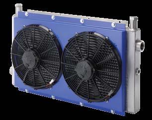
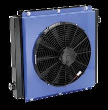
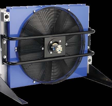
8 Industrial BOL NEW! options BOL exchanger units provide outstanding heat dissipation in industrial oil cooling applications. Select from our broad line of standard units that lead the industry as the most rugged, light weight and compact solution for extreme heat loads. Available with AC or hydraulic fan motors, all feature proven brazed aluminum P-Bar plate and bar core technology engineered with an aggressive turbulator that produces ultra high heat transfer. Choose BOL standard units with flow rates ranging from 2gpm to 200gpm. BOL is now available with two new bypass valve options: a Factory installed integrated bypass relief valve in the cooler tank inlet line and a temperature controlled bypass valve with integrated pressure relief. Features n Bar and Plate Brazed Aluminum Core n Rugged, lightweight, and compact n Provides the best heat transfer per given envelope size while minimizing pressure drop n Air-side fin design minimizes fouling and static pressure ensuring long-term, reliable performance Materials n Mounting Feet Steel n Standard Core Brazed Aluminum Plate & Bar (T-Bar is optional) n Tanks 5052 Aluminum n Nose Bar & Little Bar 3003-H Aluminum n Air Fin, Plate, Turbulator & End Plate 3003-O Aluminum n Fanguard & Shroud Steel n Connectors Aluminum n Fan Aluminum Hub, Plastic Blades n Motor TEFC & IEC n Welded fittings/ports and manifolds ensure structural integrity n Standard SAE ports NPT and BSPP ports available n Customized units are available to meet your specific performance requirements n Additional capabilities for radiators, charge-aircoolers, condensers, and multi-circuit units Ratings n Maximum Operating Pressure 250 psi (17 BAR) n Maximum Operating Temperature 300 F (150 C) n T-BAR core option for high viscosity oils or other highly fouling fluids. *See T-Bar Performance Curve n Low Noise option available n Optional Pressure Relief Bypass Valve (P-Bar) n Optional Temperature Controlled Bypass Valve with integrated pressure relief (T-Bar) Fluid Compatibility n Petroleum/mineral oils n Oil/water emulsion n Water/ethylene glycol Dimension Range HEIGHT WIDTH DEPTH* Model Inches mm Inches mm Inches mm BOL BOL BOL BOL BOL BOL BOL BOL BOL *Depth does not include the motor. Width Depth Height

 and in applications where rapid flow changes occur in the oil return line.")
9 Bypass Valve Options TTP now offers two bypass valve options on BOL a factory installed integrated relief valve and a temperature controlled bypass valve with integrated pressure relief. These valves help to avoid problems caused by above normal pressure peaks and to protect the hydraulic system from the frequency of normal pressure shocks. Pressure Relief Bypass Valve Temperature Controlled Thermal Bypass Valve with Integrated Pressure Relief This option offers factory installation of an integrated bypass relief valve in the cooler tank inlet line. Available on P-Bar. Pressure peaks are possible in cold start conditions (when the oil is extremely viscous) and in applications where rapid flow changes occur in the oil return line. A partial bypass relief helps avoid overstressing the cooler core in these conditions. This bypass valve also guards against the impact of high oil flows / peak volumes present in the return line when hydraulic cylinders are used. These valves are used to avoid problems caused by above normal pressure peaks and to protect the hydraulic system from the frequency of normal pressure shocks. Note that in conditions with frequent high pressure excursions and high pressure spikes, this option is NOT recommended. Function In most systems a bypass valve option is strongly recommended. A bypass relief valve effectively protects the cooler core against fluctuations toward peak pressure due to conditions that occur during cold starts or high cyclical return flow rates. The internal bypass is a simple cartridge check valve installed (welded) near the inlet tank of the oil cooler. This bypass feature should always be an option on systems utilizing cylinders that cause cyclical flow peaks in the return line. The internal bypass is ideal for small flow rates in normal applications. An external bypass should be considered for large flow applications or where full bypass flows are desired. The temperature controlled bypass valve functions similarly to a pressure controlled bypass, but with a temperature controlled opening pressure the hotter the oil, the higher the opening pressure. Available for single-pass T-Bar only. Function Temperature controlled bypass valves provide protection for the cooler core through their function as thermostats, enabling rapid increase in oil temperature and viscosity. These bypass valves are direct acting screw-in cartridges (M27x2 threads suitable). Depending on the temperature of the oil, they route oil flow either around the cooler core via bypass tube or through the cooler core. When the oil is cold (< 60 C), the internal valve connection P T, is open (bypassing mode), directing the flow to the tank with minimal head loss and enabling rapid increase in oil temperature. After the changeover temperature is reached (> 60 C), the integral wax thermostat element closes the connection P T and the valve directs the oil flow through the cooler core. With an integral pressurerelief function, the bypass thermostat cartridge also safeguards the cooler by protecting it from any pressure peaks that may result from excessive flow. Features and Benefits n Temperature dependent bypass of oil n Fast oil temperature rise (cold start phase) n Integrated pressure relief function protects against pressure peaks n Several temperature and pressure settings n All external parts zinc plated and chromite (CrVi) free, making it suitable for use in the harshest operating environments n Low head loss n High functional reliability and stability n Great durability without the need to install multiple external components saves time and money 9
10 Dimensions BOL-4 BOL-8 through BOL-1600 #12 SAE G B N BOL 8-30 AIR FLOW C APPROXIMATE P BOL AIR FLOW AIR FLOW 9.78 [248] [274] D A DRAIN M8 BOLT 4 PLACES DRAIN H F E.53 (13.46) HOLE (-8, -16).44 X 1.00 (11.18 X 25.40) SLOT (-30, -400).44 X 1.50 (11.18 X 38.10) SLOT (-725 THRU -1600) 2 EACH END K L M J BOL ( ) ( ) 1.38 (35.05) 2" SAE 4-BOLT FLANGE (679.96) APPROX 8.76 (222.50) 5.51 (139.95) (896.62) (922.02) AIR FLOW (982.73) ( ) (254.00).44 X 1.50 (11.18 x 38.10) SLOT 4 PLACES 1/4 NPT DRAIN ( ) ( ) (50.80) 7.59 (192.79) 7.59 (192.79) 7.59 (192.79) (679.70) (50.80) Model A B C D E F SAE G NPT & BSPP H J K L M N P BOL-4 See diagram above #12 SAE 3/4 See diagram above BOL-8 BOL-16 BOL-30 BOL-400 BOL-725 BOL-950 BOL BOL BOL (319) (415) (511) (480) (594) (705) (721) (927) (402) (500) (670) (568) (768) (940) (1041) (1041) (405) (417) (454) 18.6 (472) (446) (576) (611) (646) (288) (383) (495) (440) (549) (624) (624) (833) 4.51 (115) 4.57 (116) 5.26 (134) 6.50 (165) 6.50 (165) 9.50 (241) 5.50 (140) 9.50 (241) 0.57 (14) 0.57 (14) 1.32 (340 (51) (51) (51) (51) (51) #12 SAE 3/4 #12 SAE 3/4 #20 SAE 1¼ #20 SAE 1¼ #20 SAE 1¼ 2 SAE 4 BOLT FLANGE (361) (465) (628) (567) (765) (911) (1023) (1023) 3.36 (85) 3.35 (85) 4.15 (105) 4.15 (105) 4.15 (105) 6.05 (154) 6.05 (154) 6.05 (154) 3.74 (95) 3.74 (95) (234) 9.20 (234) 9.20 (234) 7.87 (200) 7.87 (200) 9.9 (251) 9.9 (251) 9.9 (251) 16 (406) 16 (406) 16 (406) See diagram above 2 See diagram above M8 BOLT (2PL) M8 BOLT (2PL) M8 BOLT (4PL) M8 BOLT (4PL) M10 BOLT (4PL) M10 BOLT (4PL) M10 BOLT (4PL) M10 BOLT (4PL) (355) (456) (618) (510) (710) ) (970) (970) 3.63 (92) 3.63 (92) (178) 8.75 (222) 8.75 (222) Approx. Ship Wt. lbs (kg) 18 (8.16) 45 (20.4) 55 (24.94) 125 (56.70) 148 (67.13) 170 (77.11) 300 (136.08) 430 (195.04) 515 (233.60) 582 (264.00) Note: We reserve the right to make reasonable design changes without notice. All dimensions are in inches (millimeters) unless noted otherwise. 10
11 Dimensions with Bypass BOL BOL-8 BOL-1600 #16 SAE OPTIONAL & REVERSIBLE BYPASS 25/60 PSI ASSEMBLY B N C APPROXIMATE P G D BOL 8-30 AIR FLOW BOL AIR FLOW A M E BOL-2000 #16 SAE SERVICABLE 25/60 PSI BYPASS ASSEMBLY REVERSIBLE DRAIN H " SAE 4-BOLT FLANGE F.53 (13.46) HOLE (-8, -16).44 X 1.00 (11.18 X 25.4) SLOT (-30, -400).44 X 1.50 (11.18 X SLOT (-725 THRU -1600) 2 EACH END K APPROXIMATE L J 8.76 [223] AIR FLOW X 1.50 SLOT 4 PLACES 1/4 NPT DRAIN [193] 7.59 [193] [193] 51 Model A B C D E F BOL-8 BOL-16 BOL-30 BOL-400 BOL-725 BOL-950 BOL BOL (390) (485) (601) (546) (656) (766) (766) (972) (402) (500) (670) (568) (768) (940) (1041) (1041) (405) (417) (454) 18.6 (472) (446) (576) (611) (646) (288) (383) (495) (440) (549) (624) (624) (833) 4.51 (115) 4.57 (116) 5.26 (134) 6.50 (165) 6.50 (165) 9.50 (241) 5.50 (140) 9.50 (241) 0.57 (14) 0.57 (14) 1.32 (340 (51) (51) (51) (51) (51) SAE G NPT & BSPP #12 SAE 3/4 #12 SAE 3/4 #20 SAE 1¼ #20 SAE 1¼ #20 SAE 1¼ 2 SAE 4 BOLT FLANGE H J K L M N P (361) (465) (628) (567) (765) (911) (1023) (1023) 3.36 (85) 3.35 (85) 4.15 (105) 4.15 (105) 4.15 (105) 6.05 (154) 6.05 (154) 6.05 (154) 3.74 (95) 3.74 (95) (234) 9.20 (234) 9.20 (234) 7.87 (200) 7.87 (200) 9.9 (251) 9.9 (251) 9.9 (251) 16 (406) 16 (406) 16 (406) M8 Bolt (2PL) M8 Bolt (2PL) M8 Bolt (4PL) M8 Bolt (4PL) M10 Bolt (4PL) M10 Bolt (4PL) M10 Bolt (4PL) M10 Bolt (4PL) BOL-2000 See diagram above 2 See diagram above (355) (456) (618) (510) (710) ) (970) (970) 3.63 (92) 3.63 (92) (178) 8.75 (222) 8.75 (222) Approx. Ship Wt. lbs (kg) 60 (27.22) 70 (31.75) 140 (63.50) 162 (73.48) 185 (83.92) 315 (142.88) 445 (201.85) 530 (240.40) 597 (270.79) Note: We reserve the right to make reasonable design changes without notice. All dimensions are in inches (millimeters) unless noted otherwise. 11
12 Specifications Electric Motor Information (60 Hz Nema Frame) Full Load Thermal Sound Model CMM CFM Motor HP Voltage Phase Amps 230V Frequency RPM Frame Overload db(a) at 3ft BOL / Hz BOL /3 115/ Hz C No 80 BOL / / Hz C No 80 BOL /2 115/ Hz C No 85 BOL / / Hz C No 85 BOL /2 115/ Hz C No 85 BOL / / Hz C No 85 BOL / Hz C No 97 BOL / Hz C No 97 BOL /2 115/ Hz C No 100 BOL / / Hz C No 100 BOL /2 115/ Hz TC No 92 BOL / / Hz TC No 92 BOL / Hz TC No 94 BOL / Hz TC No 96 BOL / Hz TC No 98 Electric Motor Information (50 Hz IEC Frame) Sound Model CMM CFM KW Voltage Phase Frequency RPM Frame db(a) at 3ft BOL / Hz BOL / Hz BOL / Hz BOL / Hz BOL / Hz BOL / Hz BOL / Hz BOL / Hz BOL / Hz BOL / Hz Hydraulic Motor Information Oil Flow Min. Pressure Motor IN 3 /REV Sound required Required (CM 3 /REV) db(a) Model GPM (LPM) PSI (BAR) Displacement at 3 ft. BOL (12.49) 400 (27.58) 0.22 (3.6) 80 BOL (12.49) 400 (27.58) 0.22 (3.6) 80 BOL (12.49) 500 (34.47) 0.22 (3.6) 85 BOL (12.87) 500 (34.47) 0.45 (7.3) 85 BOL (12.49) 425 (29.30) 0.22 (3.6) 97 Notes: Maximum Pressure is 2000 psi. Stated Minimum Operating Pressure is at Inlet Port of Motor psi Allowable Back Pressure. Oil Temperature Typical operating temperature ranges are: Hydraulic Motor Oil 120 F F (49 C C) Hydrostatic Drive Oil 160 F F (71 C C) Engine Lube Oil 180 F F (82.2 C C) Automatic Transmission Fluid 200 F F (93.3 C C) Desired Reservoir Temperature Oil Temperature: Oil coolers can be selected using entering or leaving oil temperatures. Off-Line Recirculation Cooling Loop: Desired reservoir temperature is the oil temperature entering the cooler. Oil Flow Min. Pressure Motor IN 3 /REV Sound required Required (CM 3 /REV) db(a) Model GPM (LPM) PSI (BAR) Displacement at 3 ft. BOL (12.49) 675 (27.58) 0.22 (3.6) 100 BOL (38.23) 300 (34.47) 1.4 (22.9) 92 BOL (38.23) 700 (34.47) 1.4 (22.9) 94 BOL (38.23) 1100 (29.30) 1.4 (22.9) 96 BOL (38.23) 1650 (113.76) 1.4 (22.9) 98 Return Line Cooling: Desired reservoir temperature is the oil temperature leaving the cooler. In this case, the oil temperature change must be determined so that the actual oil entering temperature can be found. Calculate the oil temperature change (oil #T) with this formula: Oil #T = (BTU s/hr.) / (GPM Oil Flow x 210). To calculate the oil entering temperature to the cooler, use this formula: Oil Entering Temp. = Oil Leaving Temp + Oil #T. Oil Pressure Drop: Most systems can tolerate a pressure drop through the heat exchanger of 20 to 30 PSI. Excessive pressure drop should be avoided. Care should be taken to limit pressure drop to 5 PSI or less for case drain applications where high back pressure may damage the pump shaft seals. 12
13 Selection Procedure BOL Step 1 Step 2 Determine Heat Load. Typical Rule of Thumb, -size cooler for 1/3 of the input horsepower. Heat load may be expressed as either Horsepower or BTU/Hr or KW/ C. HP=BTU/HR 2545 BTU/HR=HP x 2545 BTU/HR = KW x x E.T.D.( F) C Determine Entering Temperature Difference. (Actual E.T.D.) E.T.D. = Entering oil Entering Ambient temperature air temperature Correction Factor Pressure Drop The entering oil temperature is generally the maximum desired system oil temperature. Entering air temperature is the highest Ambient Air temperature the application will see Viscosity (SSU) Step 3 Step 4 Step 5 Determine the Corrected Heat Dissipation to use the Curves English Version Corrected (BTU/Hr) 100 F Heat Rejection = x Heat Load Desired E.T.D. (BTU/HR) to use with selection chart Metric Version Corrected KW Heatload (kw) = Heat Rejection C Desired E.T.D. ( C) Select Model From Curves Enter the Performance Curves at the bottom with the GPM oil flow and proceed upward to the adjusted Heat Rejection from Step 3. Any Model or Curve on or above this point will meet these conditions. Calculate Oil Pressure Drop Find the oil pressure drop correction factor and multiply it by the Oil Pressure Drop found on performance curve. Listed Performance Curves are based on: 50 SSU (11 cst) oil 100 F (55.56 C) Entering Temperature Difference (E.T.D.) If your application conditions are different, then continue with the selection procedure. Oil Temperature Typical operating temperature ranges are: Hydraulic Motor Oil 120 F F (49 C C) Hydrostatic Drive Oil 160 F F (71 C C) Engine Lube Oil 180 F F (82.2 C C) Automatic Transmission Fluid 200 F F (93.3 C C) Desired Reservoir Temperature Oil Temperature: Oil coolers can be selected using entering or leaving oil temperatures. Off-Line Recirculation Cooling Loop: Desired reservoir temperature is the oil temperature entering the cooler. Return Line Cooling: Desired reservoir temperature is the oil temperature leaving the cooler. In this case, the oil temperature change must be determined so that the actual oil entering temperature can be found. Calculate the oil temperature change (oil #T) with this formula: Oil #T = (BTU s/hr.) / (GPM Oil Flow x 210). To calculate the oil entering temperature to the cooler, use this formula: Oil Entering Temp. = Oil Leaving Temp + Oil #T. Oil Pressure Drop: Most systems can tolerate a pressure drop through the heat exchanger of 20 to 30 PSI. Excessive pressure drop should be avoided. Care should be taken to limit pressure drop to 5 PSI or less for case drain applications where high back pressure may damage the pump shaft seals. 13
 = 10 PSI (0.")
14 Performance Curves BOL Models with Standard P-BAR Core 1,000, , ,000 BOL-2000 BOL Note: Derate heat rejection values 15% if using 50Hz motors. Heat Rejection 100F ETD 400, , , ,000 80,000 60,000 40,000 20,000 BOL-16 BOL-8 BOL-4 BOL-725 BOL-30 BOL-400 BOL-1200 BOL-950 Oil P = 5 PSI (0.34 BAR) = 10 PSI (0.69 BAR) = 15 PSI (1.03 BAR) = 20 PSI (1.38 BAR) Heat Rejection KW/ C 10,000 1 (3.79) 2 (7.57) 4 (15.14) 6 (22.71) 10 (37.85) 20 (75.71) 40 (151.42) Oil Flow GPM (LPM) 60 (227.12) 100 (378.54) 200 (757.08) 400 ( ) 0.05 BOL Models with Optional T-BAR Core 1,000, ,000 BOL Note: Derate heat rejection values 15% if using 50Hz motors. 600,000 BOL , ,000 BOL-1200 BOL Heat Rejection 100F ETD 200, ,000 80,000 60,000 40,000 20,000 BOL-16 BOL-8 BOL-4 BOL-725 BOL-30 BOL-400 Oil P = 5 PSI = 10 PSI (0.34 BAR) (0.69 BAR) Heat Rejection KW/ C Optional T-Bar core section cutaway 10,000 1 (3.79) 2 (7.57) 4 (15.14) 6 (22.71) 10 (37.85) 20 (75.71) 40 (151.42) Oil Flow GPM (LPM) 60 (227.12) 100 (378.54) 200 (757.08) 400 ( )
15 Performance Curves BOL BOL Models with Low-Noise Option The low noise option offers the BOL models with a reduced motor speed. This allows a lower sound level output for noise-sensitive applications. Available on 60 Hz Nema frame only. 1,000, ,000 BOL-2000-LN BOL-1600-LN ,000 BOL-1200-LN 2.1 Heat Rejection 100F ETD 300, , ,000 80,000 60,000 40,000 BOL-16-LN BOL-950-LN BOL-725-LN BOL-30-LN BOL-400-LN Heat Rejection KW/ C BOL-8-LN 20, ,000 1 (3.79) 2 (7.57) 4 (15.14) 6 (22.71) (37.85) (75.71) (151.42) (227.12) Oil Flow GPM (LPM) 100 (378.54) ( ) Electric Motor Information Model HP Frame Low Noise RPM Low Noise CFM Low Noise CMM Voltage 8-1PH / PH / PH / PH / PH C / PH C / PH C / PH C / PH C / PH C / PH TC / PH TC / PH TC / PH 184TC / PH TC / Frequency (HZ) Sound Data Model DBA at 3 ft BOL-8-LN 62 BOL-16-LN 69 BOL-30-LN 67 BOL-400-LN 72 BOL-725-LN 82 BOL-950-LN 76 BOL-1200-LN 75 BOL-1600-LN 78 BOL-2000-LN 85 Low noise ratings are lab tested in a 1/4 spherical pattern. Additional nearby objects can increase the sound level. 15


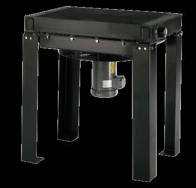
16 Industrial AOL AOL models offer vertical air flow and endless mounting possibilities, with detachable mounting legs. Select from our broad line of standard units that lead the industry as the most rugged, light weight and compact solution for extreme heat loads. Available with AC or hydraulic fan motors, all feature proven brazed aluminum P-Bar plate and bar core technology engineered with an aggressive turbulator that produces ultra high heat transfer. Choose AOL standard units with flow rates ranging from 15gpm to 350gpm. Features n Large oil flow n High performance n Industrial duty n Brazed aluminum bar and plate core n Compact all aluminum core assembly n Ideal for converting water cooled equipment to air cooled n Eliminates high water and sewer costs n Eliminates corrosion problems associated with water cooled units n Vertical air flow works well for heat recovery n State-of-the-art heat transfer technology n Hydraulic motors available n Optional SAE ports n Marine corrosion control coatings available n High performance air side fin design n Detachable legs n CRN available Materials Ratings Fluid Compatibility n Legs Steel with Baked Enamel Finish n Standard Core Brazed Aluminum Plate & Bar n Tanks 5052 Aluminum n Nose Bar & Little Bar 3003-H Aluminum n Air Fin, Plate, Turbulator & End Plate 3003-O Aluminum n Fan Aluminum Hub, Plastic Blades n Motor TEFC & IEC n Maximum Operating Pressure 250 psi (17 BAR) n Maximum Operating Temperature 300 F (150 C) n CRN Rating 235 psi at 250 F (121 C) n Petroleum/mineral oils n Oil/water emulsion n Water/ethylene glycol Dimension Range HEIGHT WIDTH DEPTH Model Inches mm Inches mm Inches mm AOL AOL AOL AOL AOL AOL AOL AOL AOL Width Depth Height
17 Dimensions AOL B A L J F H IN OR OUT OPTIONAL.62 [15.75] 4 PLACES D APPROXIMATE K G C AIR FLOW H IN OR OUT OPTIONAL VENT/DRAIN PLUG E Model A B C D Approx E F G AOL-400 AOL-725 AOL-950 AOL-1200 AOL-1600 AOL-2000 AOL-2500 AOL-3000 AOL (864) (864) (915) (915) (914) (914) (914) (914) (915) (456) (568) (681) (681) (887) (964) (1107) (1331) (1430) (574) (774) (946) (1046) (1048) (1295) (1248) (1295) (1295) (382) (443) (579) (733) (546) (679) (679) (749) (775) (762) (762) (762) (762) (762) (762) (762) (762) (762) (355) (466) (579) (579) (785) (862) (1005) (1229) (1329) (473) (673) (845) (944) (946) (1194) (1146) (1194) (1194) H NPT & BSPP H SAE J K L #32 SAE 2-1/2-12 UN-2B /2 SAE Bolt FLG SAE 4 Bolt FLG Note: We reserve the right to make reasonable design changes without notice. All dimensions are in inches (millimeters) unless noted otherwise (151) 5.67 (144) 5.86 (149) 6.09 (155) 7.98 (203) 8.00 (203) 8.07 (205) 8.21 (209) 8.00 (203) 1.75 (44) 1.75 (44) 2.76 (70) 2.76 (70) 2.75 (70) 2.75 (70) 2.75 (70) 2.75 (70) 2.76 (70) 1.00 (25) 1.00 (25) 1.39 (35) 1.39 (35) 1.44 (37) 1.16 (30) 1.00 (25) 1.06 (27) 1.52 (39) Net Wt lbs (kg) 109 (49) 151 (68) 221 (100) 296 (134) 355 (161) 482 (219) 555 (252) 724 (328) 760 (345) Approx. Ship Wt lbs (kg) 148 (67) 170 (77) 300 (136) 430 (195) 515 (234) 582 (264) 655 (297) 825 (374) 860 (390) Electric Motor & Fan Data (1) (60 Hz Nema Frame) Model AOL-400 AOL-725 AOL-950 AOL-1200 Fan CMM Fan CFM Motor H.P. Voltage Phase Full Load Amps 230V (1) Published electrical ratings are approximate, and may vary because of motor brand. Actual ratings are on motor nameplate. (2) May also be operated at 50 hz. Consult factory for details. (3) 50 Hz voltage: / (4) 50 Hz voltage: / All motors shown are TEFC Other motor options available upon request. Frequency (Hz) RPM Nema Frame Thermal Overload / (2) C No / / /460 (3) 3 3.6/3.2 50/ / C No / (2) C No / / /460 (4) 3 4.8/4.2 50/ / C No / (2) TC No / (2) TC No (2) TC No / (2) TC No 96 AOL / (2) TC No 98 AOL / (2) TC No 98 AOL / (2) TC No 98 AOL / (2) TC No 102 AOL / (2) TC No 102 Sound db(a) at 3 ft. 17
18 Specifications Electric Motor Information (50 Hz IEC Frame) Model CMM CFM KW Voltage Phase Frequency RPM Frame Sound db(a) at 3 ft. AOL /400/ Hz AOL /400/ Hz AOL /400/ Hz AOL /400/ Hz AOL /400/ Hz AOL /400/ Hz AOL /400/ Hz AOL /400/ Hz AOL /400/ Hz All IEC frame motors have CE mark. IEC motor voltages have +/- 5% tolerance. Electric Motor Information (AOL-Low Noise) Model HP Nema Frame LN RPM LN CFM LN CMM Voltage Frequency (Hz) Sound db(a) at 3 ft. AOL-400-1PH-LN 1 56C / AOL-400-3PH-LN 1 56C / AOL-725-1PH-LN C / AOL-725-3PH-LN C / AOL-950-3PH-LN TC / AOL PH-LN TC / AOL PH-LN 2 184TC / AOL PH-LN 5 213TC / AOL PH-LN 5 213TC / AOL PH-LN 5 215TC / AOL PH-LN* TCZ / Available in 60 Hz Nema Frame only. *The AOL PH-LN model has a custom motor. Low noise ratings are lab tested in a 1/4 spherical pattern. Additional nearby objects can increase the sound level. Hydraulic Motor Information Model Oil Flow Required GPM (LPM) Minimum Pressure Required PSI (BAR) Motor IN 3 /REV (CM 3 /REV) Displacement Sound db(a) at 3 ft. AOL (12.49) 425 (29.31) 0.22 (3.6) 97 AOL (12.49) 675 (46.54) 0.22 (3.6) 100 AOL (38.23) 300 (20.68) 1.4 (22.94) 92 AOL (38.23) 725 (50.00) 1.4 (22.94) 94 AOL (38.23) 1100 (75.84) 1.4 (22.94) 98 AOL (38.23) 1650 (113.76) 1.4 (22.94) 98 AOL (38.23) 1650 (113.76) 1.4 (22.94) 98 AOL (38.23) 2000 (137.90) 1.4 (22.94) 102 AOL (38.23) 2000 (137.90) 1.4 (22.94) 102 Notes: Maximum Pressure is 2000 psi. Stated Minimum Operating Pressure is at Inlet Port of Motor psi Allowable Back Pressure. Selection Procedure Performance Curves based on 100 F (56 C) E.T.D. or Entering Temperature Difference (E.T.D = Entering oil temperature minus ambient air temperature). SAE # F (93.33 C). Oil pressure drop coding: X = 5 PSI (.345 BAR) l = 10 PSI (.689 BAR) = 15 PSI (1.03 BAR) s = 20 PSI (1.38 BAR) n = 30 PSI (2.10 BAR) E.T.D. temperature correction formula: English Version 100 HP Curve = HP To Be Removed X Desired E.T.D METRIC Version KW Heatload (KW) = C Desired E.T.D. ( C) Conversion HP = KW = X.745 X E.T.D. ( F) C Notes 1. A three-way thermostatic valve is recommended to bypass the cold oil around the heat exchanger during start up. 2. Support piping as needed. Flexible connectors must be properly installed to validate warranty. 3. Coolers should not operate in ambient temperatures below 35 F (1 C). Consult factory for recommendations. 4. The fan cannot be cycled. 5. AOL coolers operated outdoors must be protected from weather. Consult factory for recommendations. 6. If duct work or additional static resistance is added to the cooler airstream, an auxiliary air mover may be required. 7. Can be mounted for horizontal air flow, with oil in at bottom port. Maintenance Periodic cleaning of the fins with compressed air is needed to remove the accumulation of dirt and dust. If the inside of the tubes need to be cleaned of oil and carbon, use a chlorinated solvent. Do not use strong solvents. Do not use acids or caustic cleaners. 18
19 Performance Curves AOL AOL Standard Option Derate heat rejection values 15% if using 50Hz motors. 500 Oil P = 5 PSI (0.34 BAR) = 10 PSI (0.69 BAR) = 15 PSI (1.03 BAR) = 20 PSI (1.38 BAR) = 30 PSI (2.75 BAR) 6.7 Horsepower Removed in 100 F ETD Heat Rejection (KW/ C) (37.85) 20 (75.71) 30 ( ) 40 (151.42) 60 (227.12) 80 (302.83) 100 (378.54) 200 (757.08) ( ) ( ) GPM (LPM) Oil Through Cooler AOL Low Noise Option Available in 60 Hz Nema Frame only. Horsepower Removed in 100 F ETD Oil P = 5 PSI (0.34 BAR) = 10 PSI (0.69 BAR) = 15 PSI (1.03 BAR) = 20 PSI (1.38 BAR) = 30 PSI (2.75 BAR) AOL-3500-LN AOL-3000-LN AOL-2500-LN AOL-2000-LN AOL-1600-LN AOL-1200-LN AOL-950-LN Heat Rejection (KW/ C) 0 10 (37.85) 20 (75.71) 30 (113.56) 40 (151.42) 60 (227.12) 80 (302.83) AOL-725-LN AOL-400-LN 100 (378.54) 200 (757.08) 300 ( ) 400 ( ) ( ) Flow Rate GPM (LPM) 19
20 Accessories Brushless DC Pulse Width Modulation (PWM) Sensor Harness and Sensor are pre-programmed to automatically match fan speed to oil temperature, thus eliminating high inrush and operating current usage and dramatically lowering fan noise. For use with Brushless DC Fan Option Designed for 12V fans only (Models MA-32, MA-48,MA-232, MA-248). Variable Output Temperature Control Function 1 - Output (Fan): Switch to control brushless fan speed over temperature span shown Function 2 - Input (Override): (+) input switch maximum fan speed bypass Can control 1-10 brushless fans in parallel. Specifications Electrical Ratings Functions 1 & 2 Maximum steady state current 1 amps inductive or resistive Maximum steady state supply voltage 32 volts DC Minimum required supply voltage 9 volts DC Recommended fusing 5 amps Operating temperature range -40 F to 257 F (-40 C to 125 C) Exposure temperature range -40 F to 257 F (-40 C to 125 C) Installation torque 14 newton-meters (10 ft lbs) Lead wires 18 awg. SXL Wiring Diagram BSPT Thread available n When coupled with a wiring harness, this sensor will control 12V brushless motor fans based on the temperature at the sensor element (fluid). n The blue wire override function is intended to bypass the current requested operation of the fan and increase the fan rpm to its maximum output. Override switch not provided with the harness, sensor, or brushless fans. n Only use the brass hex portion of the sensor for tightening. Do not use the sensor base for tightening. n The sensor will operate a 12V brushless motor fan with a fan temperature turn on (at lowest rpm). The fan rpm will increase as the temperature increases and will reach its full on (maximum RPM). Part Number Temperature Range F (60 C)-165 F (74 C) F (74 C)-185 F (85 C) F (88 C)-215 F (102 C) Brushless DC Fan Wiring Harness Part Number Brushless DC PWM Sensor Wiring Harness Part Number
21 Accessories Brushless DC Wiring Diagram Brushless 12VDC Motor Fan The yellow Analog wire (if available) allows the motor to run without a controller in strictly on/off mode. This does not allow the ability to vary the speed. This should be wired to a simple on/off switch (if desired.) PWM Sensor TTP Interface Harness Solution TTP Interface Harness Solution Wire Function Wire Color GA Input/Output Indexing Ground Black 12 Input Pin 2 Power Red 12 Input Pin 1 Pwm White 18 Input Pin 4 Analog Yellow 18 Input Pin 3 Wire Function Wire Color GA Indexing Ground Black Pin 4 Power Red Pin 1 Pwm White Pin 2 Override Blue Pin 3 Connect the red wire to a fused switched ignition source Note : From the red wire of the sensor harness (TTP#56978). Battery Fuse holder with 30 amp ATO style Fuse Note: Red wire from the fan harness(ttp#56977). A different fuse value may be required dependant upon the brushless fan being used The white wire from the fan harness (TTP#56977) will need to be connected/spliced with the white wire of the sensor harness (TTP#56978). This can be done at a location in the harness routing deemed appropriate by the installer. Customer supplied Wiring Harness 12 VDC(+) Optional Override Switch (Positive Trigger) Note: From the blue wire of the sensor harness (TTP#56978). Connect the grounds from the fan and sensor to chassis ground Note: From the black wire of the sensor harness (TTP#56978) and the black wire of the fan. 21

 n Mounts directly to the cooler.")
 Ø 1.13 (29 mm) Ø.53 (13 mm) 1.03 (29 mm).13 (3 mm).75 (19 mm) BLUE 14 GA. MOTOR + GREEN 14 GA.")
 Specifications Operating Voltage Min/Max Voltage Current Rating Switch Type 12 or 24 VDC Systems 9 VDC / 32 VDC 25 AMPS Normally open, Low side Installation 1.")
22 Accessories PB2P Fan Controller Compact Programmable Temperature Sensor Part Number This combined sensor and controller is designed to mount directly to the Heat Exchanger. It provides accurate temperature control by cycling the electric cooling fan to maintain desired oil temperature. The single housing reduces wiring and mechanical installation. A push-button and set of LEDS is provided to indicate and select the oil temperature setting. Features n 12 or 24 volt DC operation up to 25 amps. n Temperature sensor and controller in single aluminum housing. n Select from 6 temperature settings from 100 to 200 F (38 to 93 C) n Mounts directly to the cooler. n Connector to fan is included and pre-wired. n Solid-state design, no moving parts, fully sealed. n Manual override feature built-in (all LEDs lit). n Shuts off 5 F below set point. THREAD BLACK 14 GA. GROUND RED 14 GA. +24 OR +12 VDC (44 mm) Ø 1.13 (29 mm) Ø.53 (13 mm) 1.03 (29 mm).13 (3 mm).75 (19 mm) BLUE 14 GA. MOTOR + GREEN 14 GA. MOTOR PUSH SET 2.0 (51 mm).25 (6 mm) Specifications Operating Voltage Min/Max Voltage Current Rating Switch Type 12 or 24 VDC Systems 9 VDC / 32 VDC 25 AMPS Normally open, Low side Installation 1. Insert controller sensor into sensor port on cooler. 2. Connect controller to DC fan (see wire diagram above). 3. Connect DC power to controller (see wire diagram above). 4. Push button to set controller to desired temperature. Ambient Operating Temperature -40 to +185 F (-40 to +85 C) Measurement Temperature Range -40 to +239 F (-40 to +115 C) Current Draw Setpoint Selections Selection method Enclosure Rating Sealed Housing Housing Material Weight Mounting Fan Connector 20 ma 100, 120, 140, 160, 180, 200 F Pushbutton and LEDS IP69K High-grade Automotive Potting Compound Anodized Aluminum Approx 8 oz. (.23 kg) incl. wire Thread 2 Conductor Receptacle 22

 9/64 (3.")
 Conduit Hole Specifications Product Electronic Temperature Control Setpoint Range -30 F to 212 F (-34 C to 100 C) Differential Range 1 F to 30 F (0.")
23 Accessories Electronic Temperature Control & Bulb Well Assembly (AC) Part Number This is a line voltage single-stage electronic temperature control with single-pole, double-throw relay output and LED indication. It is designed with heating or cooling modes of operation, adjustable differential, and an interchangeable temperature sensor. The control couples electronic accuracy with remote sensing capability in a NEMA 1 high-impact plastic enclosure suitable for surface or DIN-rail mounting. Pilot Duty Relay needed for 460V not offered by Thermal Transfer Products Temperature Control with NEMA 1 Enclosure Dimensions - Inches (mm) 9/64 (3.7) 2-3/8 (61) 1/2 (13) 2-15/16 (75) DIN Rail MENU 4 (102) Bulb Well Dimensions - Inches 1-9/16 (40) 7/16 (11) 2-3/8 (61) 1/4 (6) Sensor 2 (50) 6½' Sensor Lead 7/8 (22) 7/8 (22) 2-3/8 (61) (1/2 in. Trade Size) Conduit Hole Specifications Product Electronic Temperature Control Setpoint Range -30 F to 212 F (-34 C to 100 C) Differential Range 1 F to 30 F (0.5 C to 17 C) Input Voltage 120 or 208/240 VAC, 50/60 Hz Current Draw 1.8 VA Relay Electrical Ratings SPDT 120V 280V 240V NO (NC) NO (NC) NO (NC) Horsepower: 1 (0.25) hp 1 (0.33) hp 1 (0.5) hp Full Load Amps: 16 (5.8) A 9.2 (4.0) A 8.0 (4.9) A Locked Rotor Amps: 96 (3) A 55 (24) A 48 (29) A Non-Inductive Amps: 15 (10) A 10 (10) A 10 (10) A Pilot Duty: 125 VA VAC, 125 VA VAC, 50 VA 24 VAC Sensor Type Replaceable Thermistor with Reference Resistance of 2.25 K ohms at 77 F (25 C) Control Ambient Operating: 30 F to 140 F ( 34 C to 60 C) Temperature Shipping: 40 F to 185 F ( 40 C to 85 C) Ambient Humidity 0 to 95% RH Non-Condensing, Maximum Dew Point: 85 F (29 C) Control Material Case and Cover: NEMA 1 High Impact Lexan 950 Plastic. UL Listed: File E27734, Guide XAPX (Temperature Indicating and Regulating Equipment) Agency Listings CSA Approved File LR948 Class Lexan 950 is a registered trademark of the General Electric Company. The performance specifications are nominal. 23
 Function The unit generates 2 output signals: 1 x NO + 1 x NC with separately adjustable switch points (SET 1) and (SET 2).")
 minus hysteresis is reached OUT2 n With rising temperature OUT2 opens when the set value (SET2) is reached.")
 M12x1 Ø.")
24 Accessories Electronic Temperature Sensors Electronic Temperature Sensor n Process connection: 1/4 NPT n 2 switching outputs complementary hysteresis adjustable n Measuring range of F ( C) Function The unit generates 2 output signals: 1 x NO + 1 x NC with separately adjustable switch points (SET 1) and (SET 2). OUT1 n With rising temperature OUT1 closes when the set value (SET1) is reached. n With falling temperature OUT1 opens when the value (SET1) minus hysteresis is reached OUT2 n With rising temperature OUT2 opens when the set value (SET2) is reached. n With falling temperature OUT2 closes when the value (SET2) minus hysteresis is reached. The hysteresis is fixed at 5 K. pnp 500mA 2 1 9, V DC pnp mA L+ L ¼ - 18 NPT Ø 1.06 (27) M12x1 Ø.32 (8) 1 locking ring 2 setting rings (manually adjustable after unlocking) 3 LED yellow: lights if OUT1 = ON, temperature > [SET1] 4 setting marks 5 LED yellow: lights if OUT2 = ON, temperature < [SET2] 6 process connection 1/4" NPT Pin 4 = OUT1 / Pin2 = OUT (48) 1.38 (35) To obtain the setting accuracy, set both rings to minimum values, and then set desired values. All dimensions in inches (millimeters), unless noted otherwise. Sensor Port Adapters Part Number Description TO 1/2" BSPP TO 1/4" NPT TO 1/2" NPT (96) 4.15 (105.5) Technical Data Application Electrical Design Output Liquid and Gases DC PNP Operating voltage (V) Current rating (ma) 500 Short-circuit protection Reverse polarity protection Overload protection Normally open/closed complementary Yes (non-latching) Yes Yes Voltage drop < 2 Current consumption < 30 Setting Range Set point, SP / F ( / C) Reset point, rp / F ( / C) Adjustment of the switch point Shims Accuracy Setting accuracy ± 3 K Repeatability ± 0.1 K Temperature drift 0.1 / 10 K Power-on delay time 0.5 s Measuring element 1 x Pt 1000, to DIN EN 60751, class B Dynamic response T05 / T09 1/3 s* Minimum installation depth.59 inches (15 mm) Medium temperature F ( C) 293 F (145 C) max. 1 h Ambient temperature F ( C) Storage temperature F ( C) Protection IP 67, III Shock resistance DIN IEC :50 g (11 ms) Vibration resistance DIN EN :20 g ( Hz) EMC EN ESD: 4 kv CD / 8 kv AD EN HF radiated: 10 V/m EN Burst: 2 Kv EN HF conducted: 10V Housing materials Stainless steel 316L / ; PC (Makrolon); PBT (Pocan); FPM (Viton) Materials (wetted parts) Stainless steel 316L / Display Power: LED green; Switching status: LED yellow Connection M12 connector; gold-plated contacts Weight lbs (0.104 kg) 1 Operating voltage supply class 2 to culus. * According to DIN EN The values for accuracy apply to flowing water. Thermal Transfer Part Number Description Temperature Sensor, dual PNP outputs, 1/4" NPT Cover, Protective, PK wire Micro DC cordset, straight connector 51661** Bulb Well **Optional Optional Bulb Well.81 (21) 1.63 (41) 2.63 (67) 3/4 NPT 1/4 NPT 24
Fluid Cooling Mobile AOHM / AOVHM Series
 Fluid Cooling Mobile Series 0916 Performance Notes AO/AOVH Series with hydraulic motor Adjustable louvers (manual) High heat removal Heavy duty construction Wide flow range Heat removal up to 210,000 BTU/HR
A global leader in manufacturing highly engineered heat transfer technologies
 OCA SERIES A global leader in manufacturing highly engineered heat transfer technologies Brazed Aluminum Oil Coolers Thermal Transfer Products introduces a new line of high performance oil coolers featuring
Fluid Cooling Industrial COLW Series
 Fluid Cooling Industrial COLW Series 0916 COPPER & STEEL CONSTRUCTION Performance Notes Ideal for independent cooling and filtering of system oils Utilizes a high efficient EK series shell & tube (finned
Fluid Cooling Brazed Plate BPSW Series
 Fluid Cooling Brazed Plate BPSW Series 0916 STAINLESS STEEL CONSTRUCTION Performance Notes Short lead time Stacked plate Stainless steel Copper brazed (nickel option) Oil to water applications High performance
GLOBAL STANDARD COOLER
 GLOBAL STANDD COOLER AKG 009 (changes and errors expected) Sales@SouthwestThermal.com p. 888-6-8 f. 80-484-0049 www.akgcoolers.com GLOBAL STANDD Rugged Environment COOLING SYSTEMS Product Information AKG
FLUID COOLING Shell & Tube EK Series
 FLUID COOLING Shell & Tube Series COPPER & STEEL CONSTRUCTION Features Compact Size High Efficiency Finned Bundle Design Low Cost Optional Patented Built-in Surge-Cushion Relief Bypass 3/16 Tube Size Heat
Oil Coolers New DCS Dual Fan models for 45HP and 60HP cooling performance
 DC/DCS Oil Coolers New DCS Dual Fan models for 45HP and 60HP cooling performance All DC/DCS and Dual Fan models available with internal pressure bypass DC Motor Driven Cooling Fans Are A Low Cost Solution
Coolers. OK Series. Air Cooled Oil Coolers Hydraulic Symbol OK 1-11 OKF Cooling Systems Catalog. Applications
 OK Series Air Cooled Oil Coolers Hydraulic Symbol OK 1-11 OKF 3-11 OKA 4-6 OKAF 4-6 OKA 8-11 OKAF 8-11 Description The OK Series cooler design uses a axial fan assembly which draws air through the cooler.
Fluid Cooling Industrial & Mobile OCA Series
 Fluid Cooling Industrial & Mobile OCA Series 0916 Performance Notes Young Radiator OCS interchange (approximate) American Industrial AOCS interchange (approximate) High efficiency, light weight, low fouling
THERMAL SYSTEMS, INC.
 C Oil Coolers SERIES World Class Advanced Technology Design Rugged Bar and Plate Construction Protects Against Fin Damage Competitive Pricing, Deliveries From Stock Leak Free SAE O-Ring Oil Connections,
GLOBAL STANDARD COOLER
 GLOBAL STANDD COOLER AKG 2009 (changes and errors expected) GLOBAL STANDD Rugged Environment COOLING SYSTEMS Product Information AKG CooL-Line is a standard line of products from the market leader in high
GLOBAL STANDARD COOLER
 GLOBAL STANDD COOLER AKG 2009 (changes and errors expected) GLOBAL STANDD RUGGED ENVIRONMENT COOLING SYSTEMS PRODUCT INFORMATION AKG CooL-Line is a standard line of products from the market leader in high
SERIES. Dirty Environment Oil Coolers ACD
 ACD Dirty Environment Oil Coolers SERIES Low Fouling Series with Non-Louvered Fin Design Standard s with Higher Speed Fans for Compact, Most Economical Selection Low Noise s with Slower Fan Speeds for
C/SSC. FLUID COOLING Shell & Tube C & SSC Series. Features. Materials SSC Series. Ratings Standard. Materials C Series.
 FLUID COOLING Shell & Tube Series COPPER/STEEL OR STAINLESS STEEL CONSTRUCTION Features API/BASCO Interchange ASME Code Option Preferred for New Oil-Water Applications C-Series / SSC Series Rugged Steel
OR STAINLESS STEEL CONSTRUCTION
 FLUID COOLING Shell & Tube Series 92 COPPER/STEEL OR STAINLESS STEEL CONSTRUCTION Features API/BASCO Interchange ASME Code Option Preferred for New Oil-Water Applications C-Series / SSC Series Rugged Steel
GLOBAL STANDARD COOLER
 COOLER RUGGED ENVIRONMENT COOLING SYSTEMS PRODUCT INFORMATION AKG CooL-Line is a standard line of products from the market leader in high performance aluminum cooling systems. AKG is best known for its
DCS- series. Classic
 DCS- series Classic Classic standard models 80 HEAT REJECTION HP @ 100F ETD 70 60 50 40 30 20 10 0 DCS60 DCS45 DCS30 DCS20 DCS16 DCS10 0 10 20 30 40 50 60 70 80 90 OIL FLOW - GPM Specifications: Maximum
AOHM. Fluid Cooling Mobile AOHM & AOVHM Series. How to Order. Features. Materials. Ratings
 Fluid Coolig Mobile & AOVHM Series Features AO/AOVH Series with Hydraulic Motor Adjustable Louvers High Heat Removal Heavy Duty Costructio Wide Flow Rage Heat Removal up to 210,000 BTU/Hr. Log Life Hydraulic
Table of Contents. 1. Model Designation And Unit Models Guide Specifications Technical Data Performance Data 10
 Table of Contents Page No. 1. Model Designation And Unit Models 1 2. Features 2 3. Guide Specifications 4 4. Standard Unit Components 5 5. Technical Data 6 6. Performance Data 10 7. Electrical Data 19
FLUID COOLING Shell & Tube B Series
 FLUID COOLING Shell & Tube Series WATER COOLED COPPER & STEEL CONSTRUCTION Features Young Touchstone Interchange Optional Non-Ferrous Construction Competitively Priced 1/4 or 3/8 Tubes Standard Water to
Product Catalog. NQ Series. Portable and Remote Air-Cooled Condenser Chillers 4 to 43 Tons
 Product Catalog NQ Series Portable and Remote Air-Cooled Condenser Chillers 4 to 43 Tons Page Intentionally Blank Contents Standard Features...1 Available Options...3 Oversized Pumps... 3 High Flow Unit
HYDRAULIC MOTOR FAN DRIVEN PRODUCTS
 HYDRAULIC MOTOR FAN DRIVEN PRODUCTS HEAT EXCHANGERS K & KBV SERIES HEAT-EXCHANGERS HPV SERIES I HPV Series II www.emmegiinc.com EMMEGI Heat Exchanger Features HEAT-EXCHANGERS 2 Bar & Plate Technology www.emmegiinc.com
W91/W94 Series TEMPERATURE REGULATORS. Self-Operated Temperature Regulators. Design & Operation W91 Non-Indicating W94 Dial Thermometer
 Design & Operation W91 Non-Indicating W94 Dial Thermometer Watson McDaniel reserves the right to change the designs and/or materials of its products without notice. 2010 Watson McDaniel Company CAPILLARY
AKG 2009 (changes and errors expected) HC- series. Classic
 HC- series. Classic") AKG 2009 (changes and errors expected) Classic performance hc @ 1750 RPM FAN SPEED HEAT REJECTION Horsepower Removed @ 100-F ETD 640 320 160 80 40 20 10 HC26 @ 3450 RPM HC14 @ 3450 RPM HC66 HC48 HC32 HC240
AKG 2009 (changes and errors expected) Classic performance hc @ 1750 RPM FAN SPEED HEAT REJECTION Horsepower Removed @ 100-F ETD 640 320 160 80 40 20 10 HC26 @ 3450 RPM HC14 @ 3450 RPM HC66 HC48 HC32 HC240
STOCK PRODUCTS CATALOGUE
 STOCK PRODUCTS CATALOGUE DESIGN MANUFACTURE MAINTENANCE OF HEAT TRANSFER EQUIPMENT A Heat Exchangers - Oil Coolers - HEX HEX a heat exchanger for cooling oil with water. This section contains stock heat
MEDIUM PRESSURE FILTERS
 Medium Pressure Filters 61-2999 psi Low-cost aluminum construction inline filters, provide flexibility for use in both mobile and industrial applications. Durable and light weight, these filters are ideal
SPUR GEAR PRODUCT LINE: CAST IRON PUMPS TABLE OF CONTENTS SERIES DESCRIPTION RELATED PRODUCTS OPERATING RANGE. Section 1451 Page 1451.
 Page 1451.1 TABLE OF CONTENTS Features & Benefits...2 Typical Applications...2 Port Location Options...2 Model Number Key...3 Standard Materials of Construction...3 Cutaway View & Pump Features...4 Component
12 volt & 24 volt DC motor
 www.aihti.com LP & LPR SERIES LP - LP - LP - MOILE IR COOLED LIQUID COOLERS 12 volt & 24 volt DC motor Mobile design. Operating temperature of F and pressure of PSI. Cools: Fluid power systems, lubrication
DC MOTORS NEMA FRAME SCR RATED
 NEMA FRAME SCR RATED NEMA FRAME MOTORS SCR RATED High voltage permanent magnet DC motors are typically used with an SCR (thyristor) controller in applications requiring adjustable speed and constant torque
VIKING SPUR GEAR SINGLE PUMPS SERIES SG-04, SG-05, SG-07 AND SGN-05, SGN-07 STANDARD CONSTRUCTION FEATURES
 VIKING SPUR GEAR SINGLE PUMPS FEATURES Section 34 Page 34. SERIES SG-04 and SG-05 Pumps Cutaway View.0 to.2 GPM Sizes (.0 to 2.5 m³/hr) SERIES SG-07 Pump Cutaway View 2.8 to 32.0 GPM Sizes (. to 7 m³/hr)
GLOBAL STANDARD COOLER
 COOLER OIL-To-AIR COOLING SYSTEMS WIT YDRAULIC MOTOR Product Information AKG CooL-Line is a standard line of products from the market leader in high performance aluminum cooling systems. AKG is best known
VIKING SG SERIES SINGLE PUMPS (WITH SHAFT SEAL)
") SERIES SG-04, -05, -07, -10, -14 () Page 341.1.1 OPERATING RANGE: SERIES SG-04/-05 PUMP SG Pumps (, Lip or Mechanical Sealed) Displacements No. 29 Flow Range Pressure Range Temperature Range Viscosity
SERIES SG-04, -05, -07, -10, -14 () Page 341.1.1 OPERATING RANGE: SERIES SG-04/-05 PUMP SG Pumps (, Lip or Mechanical Sealed) Displacements No. 29 Flow Range Pressure Range Temperature Range Viscosity
AH / AV. Advanced Series Unit Heaters AH / AV. Ruffneck
 The Ruffneck Advanced Series heaters are designed for rugged industrial applications and are available in 37 models from 6,000 to 1,,000 Btu/hr With a maximum operating pressure and temperature rating
AKG 2009 (changes and errors expected) GLOBAL STANDARD COOLER
 GLOBAL STANDARD COOLER") KG 2009 (changes and errors expected) GLOBL STNDRD COOLER GLOBL STNDRD OIL-TO-IR COOLING SYSTEMS WITH C-MOTOR PRODUCT INFORMTION KG CooL-Line is a standard line of products from the market leader in high
KG 2009 (changes and errors expected) GLOBL STNDRD COOLER GLOBL STNDRD OIL-TO-IR COOLING SYSTEMS WITH C-MOTOR PRODUCT INFORMTION KG CooL-Line is a standard line of products from the market leader in high
Oil/air cooler BLK. Fluidcontrol
 Fluidcontrol Oil/air cooler BLK Drives and hydraulic aggregates are used in machine construction, raw material production, maritime and many other areas. In hydraulic systems oil transfers power and motion,
G2 Industrial Grade Meters
 G2 Industrial Grade Meters The unique modular approach of the Industrial Grade Meter line allows you to section 2: g2 industrial grade meters design a meter to match your specific application. Turbine
R-4500 Rooftop Condenser (45,000 BTU) R-6160 Rooftop Condenser (24,000 BTU) RED DOT UNITS CONDENSERS
 R-6160 Rooftop Condenser (24,000 BTU) RED DOT UNITS CONDENSERS") RED DOT UNITS R-4500 Rooftop (45,000 BTU) FIRETRUCKS CRASH & RESCUE VEHICLES DUAL EVAPORATORS The R-4500 offers amazing performance for a light weight dual fan power condenser. Its high capacity gives
RED DOT UNITS R-4500 Rooftop (45,000 BTU) FIRETRUCKS CRASH & RESCUE VEHICLES DUAL EVAPORATORS The R-4500 offers amazing performance for a light weight dual fan power condenser. Its high capacity gives
R-6160 Rooftop Condenser (24,000 BTU) R-4500 Rooftop Condenser (45,000 BTU) RED DOT UNITS CONDENSERS. Crash/Fire/Rescue
 R-4500 Rooftop Condenser (45,000 BTU) RED DOT UNITS CONDENSERS. Crash/Fire/Rescue") RED DOT UNITS R-4500 Rooftop Condenser (45,000 BTU) Crash/Fire/Rescue Dual Evaporators Our largest power condenser, the R-4500 is a dual-fan unit with the capacity needed for high-performance evaporators
RED DOT UNITS R-4500 Rooftop Condenser (45,000 BTU) Crash/Fire/Rescue Dual Evaporators Our largest power condenser, the R-4500 is a dual-fan unit with the capacity needed for high-performance evaporators
PowrFlow PVX Vane Pumps
 PowrFlow PVX Vane Pumps POWRFLOW PVX VANE PUMPS YOUR SOURCE FOR VANE PUMPS FOR THE MOST DEMANDING APPLICATIONS What Makes PowrFlow PVX Vane Pumps Your Best Buy? Continental Hydraulics PowrFlow PVX Vane
Product Catalog TSE Series Scroll Central Chillers
 Product Catalog TSE Series Scroll Central Chillers Contents Features...1 Available Options...3 Hot Gas Bypass Valve... 3 Rotary Non-Fused Disconnect Switch... 3 Integral Reservoir and Pumping System...
Product Catalog TSE Series Scroll Central Chillers
 Product Catalog TSE Series Scroll Central Chillers Contents Features...1 Hot Gas Bypass Valve... 2 Rotary Non-Fused Disconnect Switch... 2 Integral Reservoir and Pumping System... 3 Remote Condenser Coil
AKG 2009 (changes and errors expected) GLOBAL STANDARD COOLER
 GLOBAL STANDARD COOLER") AKG 2009 (changes and errors expected) GLOBAL STANAR COOLER GLOBAL STANAR OIL-TO-AIR COOLING SYSTEMS WITH C-MOTOR PROUCT INFORMATION AKG CooL-Line is a standard line of products from the market leader
AKG 2009 (changes and errors expected) GLOBAL STANAR COOLER GLOBAL STANAR OIL-TO-AIR COOLING SYSTEMS WITH C-MOTOR PROUCT INFORMATION AKG CooL-Line is a standard line of products from the market leader
Catalog PowrFlowTM PVX Vane Pumps
 Catalog PowrFlowTM PVX Vane Pumps Your source for vane pumps for the most demanding applications. What Makes PowrFlow PVX Vane Pumps Your Best Buy? Continental Hydraulics PowrFlow PVX Vane Pumps deliver
Variable displacement axial piston pump type V30D
 Variable displacement axial piston pump type V30D for open circuit Pressure p max Displacement V max = 420 bar (6000 psi) = 260 cm 3 /rev (16.16 cu in/rev) 1.2 1. General description The axial piston variable
Oil/air cooler BLK. Fluidcontrol
 Fluidcontrol Oil/air cooler BLK Drives and hydraulic aggregates are used in machine construction, raw material production, maritime and many other areas. In hydraulic systems oil transfers power and motion,
Catalog HY /NA. Catalog HY /NA. Parker Hannifin Corporation Hydraulic Pump Division Marysville, Ohio USA
 Catalog HY28-6/NA PV, PVT Series Piston Pumps Variable Volume Catalog HY28-6/NA 1 Catalog HY28-6/NA Notes Series PV 2 Catalog HY28-6/NA Introduction Series PV Quick Reference Data Chart Pump Delivery Approx.
Cooling Systems Air Cooled / Liquid Cooled
 Cooling Systems Air Cooled / Liquid Cooled About HYDAC HYDAC stands for worldwide presence and accessibility to the customer. HYDAC has over 1000 distributors worldwide and more than 40+ wholly owned branches.
TRANSMISSION OIL COOLERS
 TRANSMISSION OIL COOLERS Transmission Oil Coolers Over 14 million transmissions fail every year, 9 out of 10 from overheating. Every 20 F drop in operating temperature can double oil and equipment life.
QT025A 2.4L 25 kw INDUSTRIAL SPARK-IGNITED GENERATOR SET EPA Certified Stationary Emergency
 STANDBY POWER RATING 25 kw, 31 kva, 60 z Image used for illustration purposes only Features Generator Set Benefits PROTOTYPE & TORSIONALLY TESTED PROVIDES A PROVEN UNIT UL2200 TESTED ENSURES A QUALITY
GENERAC QUIETSOURCE SERIES STANDBY GENERATORS
 GENERAC QUIETSOURCE SERIES STANDBY GENERATORS kw INCLUDES: Generac Naturally Aspirated Gaseous Fueled 4.2L Engine Liquid-Cooled Engine Generator Sets Standby Power Rating Model QT0 (Gray) - kw 60Hz Two
RED DOT UNITS. Condensers CONDENSERS PAGE 59
 CONDENSERS RED DOT UNITS Condensers PAGE 59 R-4500 Rooftop Condenser (45,000 BTU) FIRETRUCKS CRASH & RESCUE VEHICLES DUAL EVAPORATORS The R-4500 offers amazing performance for a light weight dual fan power
22 kva GENERAC STANDBY GENERATORS ISO. Liquid-Cooled Engine Generator Sets FEATURES INCLUDES:
 GENERAC STANDBY GENERATORS 22 kva INCLUDES: Generac Naturally Aspirated Gaseous Fueled 2.4L Engine Liquid-Cooled Engine Generator Sets Standby Power Rating Model QT02724MNAX - 22 kva, 50Hz, 1Ø Model QT02724RNAX
Eclipse. The Power of Design Innovation. Series
 Eclipse The Power of Design Innovation Series Pulsafeeder Technology Since 1936, Pulsafeeder has been recognized as a world leader in fluid handling and control technology. Pulsafeeder continues to deliver
FIXED DISPLACEMENT HYDRAULIC VANE PUMPS SERIE BV
 FIXED DISPLACEMENT HYDRAULIC VANE PUMPS SERIE BV BV FIXED DISPLACEMENT HYDRAULIC VANE PUMPS BV SERIES Versatility, power, compactness and low running costs are the main characteristics of B&C vane pumps.
FIXED DISPLACEMENT HYDRAULIC VANE PUMPS BV SERIES
 BV FIXED DISPLACEMENT HYDRAULIC VANE PUMPS BV SERIES Versatility, power, compactness and low running costs are the main characteristics of B&C vane pumps. All the components subject to wear are contained
Series PVP Variable Volume Piston Pumps
 Series PVP Variable Volume Piston Pumps Catalog HY28-2661-CD/US zp2 hpm12-1.p65, lw, jk 1 Notes Series PVP hpm12-1.p65, lw, jk 2 Introduction Series PVP Series Sizes 6-14 Phased Out For Reference Only
Air Cooled Exchangers With Aluminium Cooling Elements
 AIR COOLED Versacool Series Cooler AC electric models deliver more air flow resulting in greater performance while using a smaller diameter lower noise fan. Cylindrical air jet discharge pattern eliminates
HP Heat Exchanger Unit Heater
 Unit Heater Ruffneck are extra heavy duty (including heavy gauge steel construction) to meet the most demanding service and long life requirements for rugged industrial applications, such as space heating
OFFLINE SERIES GLOBAL STANDARD COOLER. p f
 OFFLINE SERIES GLOBAL STANDARD COOLER Sales@SouthwestThermal.com p. 888-6-8 f. 80-484-0049 www.akgcoolers.com OIL-to-AIR COOLING SYSTEMS Product Information AKG Offline Series, based on AKG Cool-Line Series,
GENERAC GUARDIAN SERIES STANDBY GENERATORS
 Includes: Generac Naturally Aspirated GENERAC GUARDIAN SERIES STANDBY GENERATORS kw Gaseous Fueled 1.6L Engine Two Line LCD Tri-lingual Digital Nexus Controller Isochronous Electronic Governor Closed Coolant
GENERAC GUARDIAN SERIES STANDBY GENERATORS
 GENERAC GUARDIAN SERIES STANDBY GENERATORS kw INCLUDES: Generac Naturally Aspirated Gaseous Fueled 1.6L Engine Liquid-Cooled Engine Generator Sets Standby Power Rating Model (Bisque) - kw 60Hz Two Line
GENERAC GUARDIAN SERIES STANDBY GENERATORS
 GENERAC GUARDIAN SERIES STANDBY GENERATORS kw INCLUDES: Generac Naturally Aspirated Gaseous Fueled 1.5L Engine Liquid-Cooled Engine Generator Sets Standby Power Rating Model (Bisque) - kw 60Hz Two Line
When working with original equipment manufacturers, hydraulic system designers and plant maintenance engineers, one of the key factors for long
 1 When working with original equipment manufacturers, hydraulic system designers and plant maintenance engineers, one of the key factors for long system life and low down time is to provide isolated Off
CONTINENTAL HYDRAULICS LPV SERIES AXIAL PISTON PUMPS
 CONTINENTAL HYDRAULICS LPV SERIES AXIAL PISTON PUMPS 5505 WEST 123RD STREET SAVAGE, MN 55378-1299 / PH: 952.895.6400 / WWW.CONTINENTALHYDRAULICS.COM LPV PUMPS FEATURES AND BENEFITS The LPV line of Variable
Air Cooled Exchangers With Aluminium Cooling Elements
 AIR COOLED Versacool Series Cooler AC electric models deliver more air flow resulting in greater performance while using a smaller diameter lower noise fan. Cylindrical air jet discharge pattern eliminates
GENERAC GUARDIAN SERIES STANDBY GENERATORS
 Includes: GENERAC GUARDIAN SERIES STANDBY GENERATORS kw Generac Turbocharged/Aftercooled Gaseous Fueled 2.4L Engine Two Line LCD Tri-lingual Digital Nexus Controller Isochronous Electronic Governor Closed
MOTOR SPEED PRODUCT LINE: CAST IRON PUMPS TABLE OF CONTENTS SERIES DESCRIPTION RELATED PRODUCTS OPERATING RANGE. Section 1442 Page 1442.
 Page 1442.1 TABLE OF CONTENTS Features & Benefits...2 Standard Materials of Construction...2 Specifications...2 Model Number Key...3 Cutaway View & Pump Features...3 Dimensions C, F, FH Sizes...4 Dimensions
TRANSMISSION OIL COOLERS
 MISSION OIL S ECONO-KOOL Transmission Oil Coolers The industry s first transmission cooler, the ECONO-KOOL transmission oil cooler is available in six sizes to fit a wide range of applications from sub-compacts
ACTUATORS GENERAL CATALOG
 CAD drawing data catalog is available. ACTUATORS GENERAL CATALOG ROTARY ACTUATORS VANE TYPE SERIES CONTENTS RAN (Standard Type) Basic Model and Configuration 259 Specifications 26 Order Codes 264 Dimensions
180VC WITH B5 FLANGE / M ,6 0, / M l 5,0 0,7 192 / M ,0 0,9 223
 METRIC (IEC) FRAME THYRISTOR RATED DC METRIC (IEC) FRAME MOTORS IP54 These metric dimensioned motors are built to IEC 34-1 electrical and mechanical standards. The IEC 63 and smaller frames are stocked
R-4500 Rooftop Condenser (45,000 BTU) R-6160 Rooftop Condenser (24,000 BTU) RED DOT UNITS
 R-6160 Rooftop Condenser (24,000 BTU) RED DOT UNITS") RED DOT UNITS CONDENSERS HEATERS UNDERDASH DUCTABLES BACKWALL HEADLINERS ROOFTOP R-4500 Rooftop (45,000 BTU) FIRETRUCKS CRASH & RESCUE VEHICLES DUAL EVAPORATORS The R-4500 offers amazing performance for
RED DOT UNITS CONDENSERS HEATERS UNDERDASH DUCTABLES BACKWALL HEADLINERS ROOFTOP R-4500 Rooftop (45,000 BTU) FIRETRUCKS CRASH & RESCUE VEHICLES DUAL EVAPORATORS The R-4500 offers amazing performance for
A Compact, Liquid-Cooled Variable Speed Drive for High Horsepower Applications
 A Compact, Liquid-Cooled Variable Speed Drive for High Horsepower Applications The Reliance Electric LiquiFlo AC drive combines high-performance variable speed drive technology with a patented liquid-cooling
Coolers. Air Cooled / Liquid Cooled
 Air Cooled / Liquid Cooled HYDAC stands for worldwide presence and accessibility to the customer. HYDAC has over 1000 distributors worldwide and more than 40 wholly owned branches. Our know-how has evolved
Industrial Diesel Generator Set KD1650-E 50 Hz - Emission Optimized EPA Tier 2 Compliant
 RATINGS 400V - 50 Hz Standby kva 1650 KWe 1320 Prime kva 1500 KWe 1200 Benefits & features SDMO premium quality SDMO provides one source responsibility for the generating system and accessories The generator
Disc Valve Hydraulic Motors 4000 Compact Series
 Disc Valve Hydraulic Motors 10.2014 inspired hydraulics. Änderungen und Druckfehler vorbehalten 10.2014 EN EATON_Motoren english Port B Port A Features Shuttle Valve with Back- Pressure Relief Valve Highlights
Siemens Liquid Cooled Standby Generators
 Data Sheet Siemens Liquid Cooled Standby Generators 100 kw Liquid Cooled Gas Engine Standby Power Rating 100 kw 60Hz Includes: Naturally Aspirated Gaseous Fueled 4.6L Engine Two line LCD tri-lingual digital
STANDBY GENERATOR 25 kw LIQUID-COOLED GENERATOR SET INCLUDES FEATURES. Standby Power Rating Model HT kw 60Hz
 STANDBY GENERATOR 25 kw LIQUID-COOLED GENERATOR SET Standby Power Rating Model HT025-25 kw 60Hz INCLUDES Two Line LCD Tri-lingual Digital Sync Controller Electronic Governor Closed Coolant Recovery System
Industrial Diesel Generator Set KD2500-F 50 Hz Fuel Consumption Optimized
 RATINGS 400 V - 50 Hz Standby kva 2500 KWe 2000 Prime kva 2273 KWe 1818 Benefits & features SDMO premium quality SDMO provides one source responsibility for the generating system and accessories The generator
Air Cooler Industry AC-LN 8-14 / ACA-LN 8-11 / ACAF-LN 8-11
 Air Cooler Industry AC-LN 8-14 / ACA-LN 8-11 / ACAF-LN 8-11 Symbol General The AC-LN 8-14 air cooler series can be used in all areas where either oil or water-glycol is to be cooled with air. The coolers
PRODUCT OBSOLETED 1Q16
 VIKING HEAVY DUTY PUMPS FEATURES Section 6 Page 6. Issue C 9 SERIES 27 s Cutaway View (Packed Type) 60-200-280 GPM Sizes (36-45-64 m³/hr) Shown without over-pressure relief valve MECHANICAL SEAL (SERIES
Industrial Diesel Generator Set KD1100-F 50 Hz Fuel Consumption Optimized
 RATINGS 400 V - 50 Hz Standby kva 1100 KWe 880 Prime kva 1000 KWe 800 Benefits & features SDMO premium quality SDMO provides one source responsibility for the generating system and accessories The generator
Unit Heaters. Catalog MANUFACTURERS HEATING PRODUCTS. Tel: (905) Fax: (905) OF HYDRONIC.
 Fax: (905) OF HYDRONIC.") Catalog MANUFACTURERS OF HYDRONIC HEATING PRODUCTS Tel: (905) 670-3200 Fax: (905) 670-3822 General Product Overview Sigma horizontal and vertical propeller unit heaters feature a wide performance range
Catalog MANUFACTURERS OF HYDRONIC HEATING PRODUCTS Tel: (905) 670-3200 Fax: (905) 670-3822 General Product Overview Sigma horizontal and vertical propeller unit heaters feature a wide performance range
Engine Performance 1500 RPM
 CUMMINS ENGINE COMPANY, INC Columbus, Indiana 471 ENGINE PERFORMANCE CURVE Basic Engine Model: QST-G3 Engine Critical Parts List: CPL: 284 Curve Number: FR-188 Date: 23Dec3 Q 1 Displacement :.48 liter
STANDBY GENERATOR 130 kw LIQUID-COOLED GENERATOR SET INCLUDES FEATURES. Standby Power Rating Model HT kw 60Hz
 STANDBY GENERATOR 130 kw LIQUID-COOLED GENERATOR SET Standby Power Rating Model HT130-130 kw 60Hz INCLUDES Two Line LCD Tri-lingual Digital Sync Controller Electronic Governor Closed Coolant Recovery System
STANDBY GENERATOR 100 kw LIQUID-COOLED GENERATOR SET INCLUDES FEATURES. Standby Power Rating Model HT kw 60Hz
 STANDBY GENERATOR 100 kw LIQUID-COOLED GENERATOR SET Standby Power Rating Model HT100-100 kw 60Hz INCLUDES Two Line LCD Tri-lingual Digital Sync Controller Electronic Governor Closed Coolant Recovery System
D/G-04 Series. Up to 3.0 gpm (11.3 l/min)
") D/G-4 Series Up to 3. gpm (11.3 l/min) 42 United States Instant Information: United Kingdom D/G-4 Series Performance flow max max flow input model gpm l/min rpm D/G-4-X 2.9 11. 175 D/G-4-E 2.1 7.8 175
D/G-4 Series Up to 3. gpm (11.3 l/min) 42 United States Instant Information: United Kingdom D/G-4 Series Performance flow max max flow input model gpm l/min rpm D/G-4-X 2.9 11. 175 D/G-4-E 2.1 7.8 175
Off-Line Filtration OFF-LINE FILTRATION
 Off-Line Filtration: Where and Why Used The Donaldson Filter Cart, Filter Panel and Filter Buddy offer convenient off-line filtration, flushing and fluid transfer.* Use them with your in-plant machinery
Fluid Power Conference and Expo
 Fluid Power Conference and Expo Fast & Efficient, Off-line Kidney Loop Fluid Conditioning 3 When working with original equipment manufacturers, hydraulic system designers and plant maintenance engineers,
GENERAC QUIETSOURCE SERIES STANDBY GENERATORS
 GENERAC QUIETSOURCE SERIES STANDBY GENERATORS 27 kw INCLUDES: Generac Naturally Aspirated Gaseous Fueled 2.4L Engine Liquid-Cooled Engine Generator Sets Standby Power Rating Model (Gray) - 27 kw 60Hz Two
Solutions. ydraulics. We Manufacture. H y d r a u l i c s. Char-Lynn Disc Valve Hydraulic Motors. h y d r a u l i c s
 H y d r a u l i c s ydraulics Char-Lynn Disc Valve Hydraulic Motors h y d r a u l i c s 2000, 4000, 6000, and 10,000 Series Hydraulic Motors We Manufacture 11-01-878 EN-0201 Solutions S o l u t i o n s
Industrial Diesel Generator Set KD1750-UF 60 Hz Fuel Consumption Optimized
 RATINGS 480 V - 60 Hz Standby kva 2187.50 KWe 1750 Prime kva 1989 KWe 1591 Benefits & features premium quality provides one source responsibility for the generating system and accessories The generator
T Series. The most reliable HVAC system for transit is now better than ever.
 T Series The most reliable HVAC system for transit is now better than ever. High performance and reliability for more than 30 years T-Series: The HVAC design that changed an industry. Low life cycle costs
Precision Cooling For Business-Critical Continuity. Liebert CW. System Design Manual kW, 50 & 60Hz
 Precision Cooling For Business-Critical Continuity Liebert CW System Design Manual - 26-181kW, 50 & 60Hz TABLE OF CONTENTS LIEBERT CW MODEL NUMBER NOMENCLATURE....................................1 1.0
10,000 Series. Highlights C-6
 Highlights Features higher flows Benefits demanding mobile and industrial applications from Applications Description This is the biggest disc valve motor of our line with up to 45 GPM and 24,000 in-lb
Data Bulletin. ALTIVAR FLEX58 Chassis Drive Controllers Class 8806 INTRODUCTION DESIGN CONCEPT. Bulletin No. 8806DB0102 August 2001 Raleigh, NC, USA
 Data Bulletin Raleigh, NC, USA ALTIVAR FLEX58 Chassis Drive Controllers Class 8806 INTRODUCTION The ALTIVAR FLEX58 chassis drive controller offers OEMs, panel builders, integrators, and users a unique
Industrial Diesel Generator Set KD1100-F 50 Hz Fuel Consumption Optimized
 RATINGS 400 V - 50 Hz Standby kva 1100 KWe 880 Prime kva 1000 KWe 800 Benefits & features premium quality provides one source responsibility for the generating system and accessories The generator set,
AFGP12B. Features. Efficiency: 12 SEER 80% AFUE. Warranty: 10-year limited compressor 10-year limited heat exchanger 5-year limited components
 AFGP12B Gas/Electric Package Unit Features Shipped for horizontal applications; easily converted to downshot Side-by-side horizontal discharge Standard thermostatic expansion valve Crimp-Tite weld-free
THRU DRIVE HYDRAULIC VANE PUMP TQ/TV SERIES
 THRU DRIVE HYDRAULIC VANE PUMP TQ/TV SERIES TQ/TV THRU-DRIVE HYDRAULIC VANE PUMPS TQ/TV SERIES Thru-drive pumps save installation space and cost by eliminating double shaft extension electric motors or
MICROPUMP MAG-DRIVE GEAR PUMPS
 MAG-DRIVE GEAR PUMPS REVISION # 1 DATE: 6-6-6 WETTED MATERIALS Pump housings: 316 stainless steel. Gears: PEEK. Gear shafts: 316 stainless steel. Gear shaft bearings: PEEK. Driven magnet: Totally encapsulated
VIKING. Series LVP STAINLESS STEEL VANE PUMP. VIKING PUMP A Unit of IDEX Corporation Cedar Falls, IA 2016 PRODUCT DESCRIPTION SERIES OPERATING RANGE
 Page 445.1 PRODUCT DESCRIPTION Rotary vane pumps are used for liquid transfer in applications ranging from chemicals to LP gas. Vanes extend from slots on the rotor, sweeping liquid through a cam-shaped