Direction of Helix (R) No. of Teeth (20) Module (1) Others (Ground Gear) Type (Helical Gear) Material (SCM440)
|
|
|
- Beverly Reynolds
- 6 years ago
- Views:
Transcription
 K H 1 - Direction of Helix () No.")

1 KH round Series Newly added m1 ~ 3 Page 168 SH Steel m2, 3 Page 178 CP acks acks Catalog Number of KHK Stock The Catalog Number for KHK stock gears is based on the simple formula listed below. Please order KHK gears by specifying the Catalog Numbers. ear Pair (Example) K H 1 - Direction of Helix () No. of Teeth () Module (1) s (round ear) Type ( ear) Material (SCM440) Material Type S S45C H K SCM440 Information round earboxes Feature Icons ohs Compliant Product e-machinable Product Finished Product round ear esin Product Injection Molded Product Heat Treated Product Stainless Product Copper Alloy Product Black Oxide coated Product 163 catalog_usa.indb /05/21 15:14:43


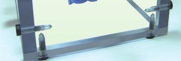
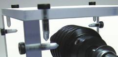
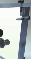
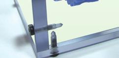
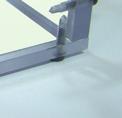
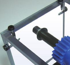
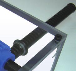
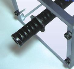
2 Characteristics KHK stock helical gears are quiet, compact and economical. They are suitable wherever you require high-speed rotation including in machine tools, speed reducers and other industrial machinery. The following table lists the main features. Selection Hints It is important to thoroughly understand the contents of the product tables as well as CAUTION notes before making the selection. You must specify the right or left hand by including the letter or in the catalog number when ordering. KH SH Module 1~3 2~3 Material SCM440 S45C Heat Treatment Thermal refined, ear teeth induction hardened Tooth Surface Finish round Cut Precision JIS B :1998 N6 N8 Secondary Operations Possible except for tooth Possible Features Have excellent strength and wear resistance which allow your designs to be more compact. Finished products for J Series are also available. Having larger contact ratios compared to the SS spur gears, effective in reducing noise and vibration. Advanced grinding equipment allows for efficient production The use of electro deposition grinding wheel produces consistent precision with shorter grinding usage, making products affordable. 1. Caution in Selecting the Mating. We have two different types of KHK helical gear products, one is a KH gear type, and the other is a SH gear type. Each type of gear has different module systems, pressure angle designations and helix angles. Since the KH are of the transverse module style, and the SH gears are of normal module style, KH and SH gears are not interchangeable. Please keep this in mind when making your selection. Also, right hand and left hand helical mating gears are packaged as a set. See the photos below for reference and for help in making a proper selection. The table shows the possible combinations. Mating ear Selection Chart ( Allowable Not allowable) & Helix Hand KH KH SH KH KHF SH H H H H H H H H H H SH H H Helix Direction eft() ight() Pinion()& ack() leason Cylindrical ear rinding Machine (Z701) Pinion()& ack() 164 catalog_usa.indb /05/21 15:14:45

 eplaces spur gears having the same module, number of teeth, and center distance.")
3 KHK Technical Information Transverse module and Normal module The difference between transverse module and normal module is defined as the difference of basic tooth form. As shown on the right, the module of tooth datum orthogonal to the center axis of gear is called transverse module. The module of tooth datum orthogonal to the thread helix is called normal module. The characteristics of each are shown as below. Characteristics of Transverse module and Normal module Style Advantages Disadvantages Transverse module (KH) eplaces spur gears having the same module, number of teeth, and center distance. Special gear cutting or grinding machines are required for processing each helix angle. Normal module Transverse module Normal module (SH) Modifications of spur gears are made by gear cutting or grinding machines, even if they have different helix angles. Have a center distance value different from that of a spur gear, although they have the same module size and the same number of gear teeth. The center distance value is rarely an integral number. CAUTION Above is for illustration purpose only and not a representation of the true tooth forms. For detailed technical information, please refer to separate technical reference book, in the section of 4.3 (Page 22). 2. Caution in Selecting Based on ear Strength Allowable bending strength and surface durability values shown in product tables were computed by assuming a certain application environment. They should be used as reference only. We recommend that each user computes his own values by applying the actual usage conditions. To find more information on gear strength calculations, please refer to separate technical reference book, in the section Bending Strength of and (Page 71) or Surface Durability of and (Page 78). Calculation assumptions for Bending Strength of Item KH SH Formula NOTE 1 Formula of spur and helical gears on bending strength(jma401-01) No. of teeth of Mating Same number of teeth otation 600rpm 100rpm Durability Over 10 7 cycles Impact from motor Uniform load Impact from load Uniform load Direction of load Bidirectional Allowable bending stress at root σ Flim (kgf/mm 2 )NOTE Safety factor S F 1.2 Calculation assumptions for Surface Durability (Except where it is common with bending strength) Item Formula NOTE 1 Kinematic viscosity of lubricant ear support KH SH Formula of spur and helical gears on bending strength(jma402-01) 100cSt(50 ) Symmetric support by bearings Allowable Hertz stress σ Hlim (kgf/mm 2 ) Safety factor SH 1.15 NOTE 1 The formula for gear strength is based on JMA Standard. The units for the rotational speed (rpm) and the load (kgf/mm 2 ) were matched to the units needed in the equation. NOTE 2 The allowable bending stress at the root σ Flim is calculated from JMA401-01, and set to 2/3 of the value in the consideration of the use of planetary-, idler-, or other gear systems, loaded in both directions. Definition of Bending Strength by JMA (1974) The allowable bending strength of a gear is defined as the allowable tangential force at the pitch circle based on the mutually allowable root stress of two meshing gears under load. Definition of Surface Durability by JMA (1975) The surface durability of a gear is defined as the allowable tangential force at the pitch circle, which permits the force to be transmitted safely without incurring surface failure. Example of the failure due to insufficient bending strength. Example of the defacement due to insufficient surface durability. 165 catalog_usa.indb /05/21 15:14:45
4 Application Hints In order to use KHK stock gears safely, carefully read the Application Hints before proceeding. If there are questions or if you require clarifications, please contact our technical department or your nearest distributor. KHK USA Inc. PHONE: FAX: Caution on Performing Secondary Operations 1 If you are reboring, it is important to pay special attention to locating the center in order to avoid runout. 2 The reference datum for gear cutting is the bore. Therefore, use the bore for locating the center. If it is too difficult to do for small bores, the alternative is to use one spot on the bore and the runout of the side surface. 3 If the rework requires using scroll chucks, we recommend the use of new or rebored jaws for improved precision. If chucking by the teeth, please apply the pressure carefully to avoid crushing the teeth which will lead to noisy gears. 4 The maximum bore size is dictated by the requirement that the strength of the hub is to be higher than that of athe Operations 5 In order to avoid stress concentrations, leave radii on the keyway corners. Tapping & Keyway Slotting 6 To avoid problems of reduced gear precision and other manufacturing difficulties, do not attempt to machine the gears to reduce face widths. 7 KH round are already stress relieved. But if you subject them to a heavy turning operation such as removing the hubs, the residual stress may cause deformation. 8 When heat-treating SH, it is possible to get thermal stress cracks. It is best to subject them to penetrant inspection afterwards. If the tooth strength is not sufficient, it can be increased approximately four times by heat-treating. On the other hand, the precision of the gear will drop about one grade. Heat Treatment If you apply induction hardening to the gear teeth of S45C products, you need to designate the hardness and where to apply the heat treatment. Below is an example of common specifications and KHK's specifications for hardening: Common Specifications for Heat Treatment Area: Tooth surface, or, Tooth surface and Tooth root Hardness: Within 10 HC in the range from 45 to 60 HC. (e.g HC) KHK s Specifications for Heat Treatment Area: Tooth surface, or, Tooth surface and Tooth root Hardness: From 50 to 60 HC. the gear teeth. The maximum bore size should be 60% to 70% of the hub diameter (or tooth root diameter), and 50% to 60% for keyway applied modifications. *Hardness and Depth of ear-teeth Induction Hardening The hardening method and the state of hardened teeth area are varied depending on the size of gears. Since different hardening treatment is applied in accordance with the module and number of teeth, the hardness level you designate is referred to as the hardness of the reference diameter. For some of our products, there may be a case that the hardness at tooth tip / root may not be equal to the hardness you designated. As to the effective case depth for S45C, it is specified by JIS, as The distance from the surface of the case to the area with hardness HV450. The case depth differs from area to area of a tooth. 166 catalog_usa.indb /05/21 15:14:46

5 KHK Technical Information 2. Points of Caution in Assembling 1 KHK stock helical gears are designed to give the proper backlash when assembled using the center distance given by the formula on the right (center distance tolerance of H7 ~ H8). The amount of backlash is given in the product table for each gear. 2 Please refer to overall length tolerance for on page Because of the helix of the gear teeth, helical gears in mesh produce thrust forces in the axial directions. The axial thrust bearings must be able to resist these forces. The direction of the thrust forces depend on the helix hand and the direction of rotation as shown below. For details, please refer to separate technical reference book, section of ear Forces (Page 107). a = d 1 + d 2 2 where a :Center Distance d1 :Pitch Diameter of Pinion d2 :Pitch Diameter of ear Direction of otation and Thrust Force driven drive Thrust Bearing drive driven ack Thrust Pinion Thrust Pinion Thrust ack Thrust Pinion Thrust drive ack Thrust ack Thrust drive Pinion Thrust Application Examples eplaceable SS2-30 KH2-30 To increase strength, the SS2-30 ear is replaced with the KH2-30 ear (mating with the left hand of KH). 167 catalog_usa.indb /05/21 15:14:47
6 KH round Module 1 acks CP acks ear Pair earboxes 168 No. of teeth Direction of helix Shape ear teeth Standard full depth Transverse pressure angle Helix angle 21 30' Material SCM440 Heat treatment Thermal refinined, tooth surface induction hardened Tooth hardness 50 ~ 60HC Face width (E) 8 Hub width (F) 10 Total length () 18 offset (J) 5 * The precision grade of J Series products is equivalent to the value shown in the table. Bore Hub dia. Pitch dia. Outside dia. Allowable torque (N m) Allowable torque (kgf m) Backlash AH7 B C D Bending strength Surface durability Bending strength Surface durability (mm) KH1- KH ~ KH KH ~ KH KH ~ KH KH ~ KH KH ~ KH KH ~ KH KH ~ KH KH ~ KH KH ~ KH KH ~ KH KH ~ KH KH ~ KH KH ~ KH KH ~ KH KH ~ KH KH ~ KH KH ~ KH KH ~ KH1-100 KH ~ [Caution on Product Characteristics] 1 The allowable torques shown in the table are calculated values according to the assumed usage conditions. Please see Page 165 for more details. 2 The backlash values shown in the table are the theoretical values for the backlash in the normal direction of a pair of identical gears in mesh. 3 These gears produce axial thrust forces. See Page 167 for more details. 4 ight handed and left handed helical gears in the same module are designed to mesh as a pair, but KH gears are not interchangeable with SH type helical gears. [Caution on Secondary Operations] Precision grade eference section of gear Specifications JIS grade N6 (JIS B1702-1: 1998) JIS grade 2 (JIS B1702: 1976) otating plane Weight (kg) 1 Please read Caution on Performing Secondary Operations (Page 166) when performing modifications and/or secondary operations for safety concerns. KHK Transverse Module Normal Module Quick-Mod, the KHK's system for quick modification of KHK stock gears is also available. * Above is for illustration purposes only and differs 2 Due to the gear teeth being induction hardened, no secondary operations can be from actual tooth forms. To find more details, performed on tooth areas including the bottom land (approx. 2 to 3 mm). please see the section 4.3 in separate technical reference book (Page 22). 3 While cutting off the entire hub may cause curvature deformation by residual stress, some products are straightened and annealed after refining the material. catalog_usa.indb /05/21 15:14:49


7 KH Series round Newly added K T T To order J Series products, please specify; +J + BOE Bore H7 Keyway Js9 size KH1- J BOE KH1- J BOE KH1-22 J BOE KH1-22 J BOE KH1-24 J BOE KH1-24 J BOE KH1-25 J BOE KH1-25 J BOE KH1-28 J BOE KH1-28 J BOE KH1-30 J BOE KH1-30 J BOE KH1-32 J BOE KH1-32 J BOE KH1-35 J BOE KH1-35 J BOE KH1-36 J BOE KH1-36 J BOE KH1-40 J BOE KH1-40 J BOE KH1-44 J BOE KH1-44 J BOE KH1-45 J BOE KH1-45 J BOE KH1-48 J BOE KH1-48 J BOE KH1-50 J BOE KH1-50 J BOE KH1-60 J BOE KH1-60 J BOE KH1-70 J BOE KH1-70 J BOE KH1-80 J BOE KH1-80 J BOE KH1-90 J BOE KH1-90 J BOE KH1-100 J BOE KH1-100 J BOE [Caution on J series] The product shapes of J Series items are identified by background color. 1 As available-on-request products, requires a lead-time for shipping within 2 working-days (excludes the day ordered), after placing an order. Please allow additional shipping time to get to your local distributor. 2 Number of products we can process for one order is 1 to units. For quantities of 21 or more pieces, we need to quote price and lead time. 3 Keyways are made according to JIS B1301 standards, Js 9 tolerance. 4 Certain products which would otherwise have a very long tapped hole are conterbored to reduce the length of the tap. 5 Areas of products which have been re-worked will not be black oxide coated. 6 For products having a tapped hole, a set screw is included. acks CP acks ear Pair earboxes You can download CAD data (DXF format) of KHK from the Web Catalog. 169 catalog_usa.indb /05/21 15:14:51
8 KH round Module 1.5 acks CP acks ear Pair earboxes 170 KH1.5- KH1.5- KH KH KH KH KH KH KH KH KH KH KH KH KH KH KH KH KH KH KH KH KH KH KH KH KH KH KH KH KH KH KH KH KH KH KH KH KH KH KH KH [Caution on Product Characteristics] [Caution on Secondary Operations] No. of teeth Direction of helix Shape ear teeth Standard full depth Transverse pressure angle Helix angle 21 30' Material SCM440 Heat treatment Thermal refinined, tooth surface induction hardened Tooth hardness 50 ~ 60HC Face width (E) 12 Hub width (F) 12 Total length () 24 offset (J) 6 * The precision grade of J Series products is equivalent to the value shown in the table. Bore Hub dia. Pitch dia. Outside dia. Allowable torque (N m) Allowable torque (kgf m) Backlash AH7 B C D Bending strength Surface durability Bending strength Surface durability (mm) Precision grade eference section of gear Specifications JIS grade N6 (JIS B1702-1: 1998) JIS grade 2 (JIS B1702: 1976) otating plane Weight (kg) ~ The allowable torques shown in the table are calculated values according to the assumed usage conditions. Please see Page 165 for more details. 2 The backlash values shown in the table are the theoretical values for the backlash in the normal direction of a pair of identical gears in mesh. 3 These gears produce axial thrust forces. See Page 167 for more details. 4 ight handed and left handed helical gears in the same module are designed to mesh as a pair, but KH gears are not interchangeable with SH type helical gears. 1Please read Caution on Performing Secondary Operations (Page 166) when performing modifications and/or secondary operations for safety concerns. KHK Quick-Mod, the KHK's system for quick modification of KHK stock gears is also available. 2Due to the gear teeth being induction hardened, no secondary operations can be performed on tooth areas including the bottom land (approx. 2 to 3 mm). 3 While cutting off the entire hub may cause curvature deformation by residual stress, some products are straightened and annealed after refining the material ~ ~ catalog_usa.indb /05/21 15:14:51
9 KH Series round Newly added To order J Series products, please specify; +J + BOE Bore H7 Keyway Js9 size K The product shapes of J Series items are identified by background color. KH1.5- J BOE KH1.5- J BOE KH J BOE KH J BOE KH J BOE KH J BOE KH J BOE KH J BOE KH J BOE KH J BOE KH J BOE KH J BOE KH J BOE KH J BOE KH J BOE KH J BOE KH J BOE KH J BOE KH J BOE KH J BOE KH J BOE KH J BOE KH J BOE KH J BOE KH J BOE KH J BOE KH J BOE KH J BOE KH J BOE KH J BOE KH J BOE KH J BOE KH J BOE KH J BOE KH J BOE KH J BOE KH J BOE KH J BOE KH J BOE KH J BOE KH J BOE KH J BOE [Caution on J series] 1 As available-on-request products, requires a lead-time for shipping within 2 working-days (excludes the day ordered), after placing an order. Please allow additional shipping time to get to your local distributor. 2 Number of products we can process for one order is 1 to units. For quantities of 21 or more pieces, we need to quote price and lead time. 3 Keyways are made according to JIS B1301 standards, Js 9 tolerance. 4 Certain products which would otherwise have a very long tapped hole are conterbored to reduce the length of the tap. 5 Areas of products which have been re-worked will not be black oxide coated. 6 For products having a tapped hole, a set screw is included. acks CP acks ear Pair earboxes You can download CAD data (DXF format) of KHK from the Web Catalog. 171 catalog_usa.indb /05/21 15:14:53
10 KH round Module 2 acks CP acks ear Pair earboxes 172 No. of teeth KH2-15 KH KH2-16 KH KH2-18 KH KH2- KH2- KH2-22 KH KH2-24 KH KH2-25 KH KH2-26 KH KH2-28 KH KH2-30 KH KH2-32 KH KH2-35 KH KH2-36 KH KH2-40 KH KH2-44 KH KH2-45 KH KH2-48 KH KH2-50 KH KH2-52 KH KH2-60 KH KH2-70 KH KH2-80 KH KH2-90 KH KH2-100 KH [Caution on Product Characteristics] [Caution on Secondary Operations] Direction of helix Shape Precision grade eference section of gear Specifications JIS grade N6 (JIS B1702-1: 1998) JIS grade 2 (JIS B1702: 1976) otating plane ear teeth Standard full depth Transverse pressure angle Helix angle 21 30' Material SCM440 Heat treatment Thermal refinined, tooth surface induction hardened Tooth hardness 50 ~ 60HC Face width (E) 16 Hub width (F) 13 Total length () 29 offset (J) 6.5 * The precision grade of J Series products is equivalent to the value shown in the table. Bore Hub dia. Pitch dia. Outside dia. Allowable torque (N m) Allowable torque (kgf m) Backlash AH7 B C D Bending strength Surface durability Bending strength Surface durability (mm) Weight (kg) ~ ~ ~ The allowable torques shown in the table are calculated values according to the assumed usage conditions. Please see Page 165 for more details. 2 The backlash values shown in the table are the theoretical values for the backlash in the normal direction of a pair of identical gears in mesh. 3 These gears produce axial thrust forces. See Page 167 for more details. 4 ight handed and left handed helical gears in the same module are designed to mesh as a pair, but KH gears are not interchangeable with SH type helical gears. 1 Please read Caution on Performing Secondary Operations (Page 166) when performing modifications and/or secondary operations for safety concerns. KHK Quick-Mod, the KHK's system for quick modification of KHK stock gears is also available. 2 Due to the gear teeth being induction hardened, no secondary operations can be performed on tooth areas including the bottom land (approx. 2 to 3 mm). 3 While cutting off the entire hub may cause curvature deformation by residual stress, some products are straightened and annealed after refining the material. catalog_usa.indb /05/21 15:14:53
11 KH Series round Newly added To order J Series products, please specify; +J + BOE Bore H7 Keyway Js9 size KH2-15 J BOE KH2-15 J BOE KH2-16 J BOE KH2-16 J BOE KH2-18 J BOE KH2-18 J BOE KH2- J BOE KH2- J BOE KH2-22 J BOE KH2-22 J BOE KH2-24 J BOE KH2-24 J BOE KH2-25 J BOE KH2-25 J BOE KH2-26 J BOE KH2-26 J BOE KH2-28 J BOE KH2-28 J BOE KH2-30 J BOE KH2-30 J BOE KH2-32 J BOE KH2-32 J BOE KH2-35 J BOE KH2-35 J BOE KH2-36 J BOE KH2-36 J BOE KH2-40 J BOE KH2-40 J BOE KH2-44 J BOE KH2-44 J BOE KH2-45 J BOE KH2-45 J BOE KH2-48 J BOE KH2-48 J BOE KH2-50 J BOE KH2-50 J BOE KH2-52 J BOE KH2-52 J BOE KH2-60 J BOE KH2-60 J BOE KH2-70 J BOE KH2-70 J BOE KH2-80 J BOE KH2-80 J BOE KH2-90 J BOE KH2-90 J BOE KH2-100 J BOE KH2-100 J BOE [Caution on J series] K The product shapes of J Series items are identified by background color. 1 As available-on-request products, requires a lead-time for shipping within 2 working-days (excludes the day ordered), after placing an order. Please allow additional shipping time to get to your local distributor. 2 Number of products we can process for one order is 1 to units. For quantities of 21 or more pieces, we need to quote price and lead time. 3 Keyways are made according to JIS B1301 standards, Js 9 tolerance. 4 Certain products which would otherwise have a very long tapped hole are conterbored to reduce the length of the tap. 5 Areas of products which have been re-worked will not be black oxide coated. 6 For products having a tapped hole, a set screw is included. acks CP acks ear Pair earboxes You can download CAD data (DXF format) of KHK from the Web Catalog. 173 catalog_usa.indb /05/21 15:14:54
12 KH round Module 2.5 acks CP acks ear Pair earboxes 174 KH KH KH KH KH KH KH2.5- KH2.5- KH KH KH KH KH KH KH KH KH KH KH KH KH KH KH KH KH KH KH KH KH KH KH KH KH KH KH KH KH KH KH KH [Caution on Product Characteristics] [Caution on Secondary Operations] No. of teeth Direction of helix Shape Precision grade eference section of gear Specifications JIS grade N6 (JIS B1702-1: 1998) JIS grade 2 (JIS B1702: 1976) otating plane ear teeth Standard full depth Transverse pressure angle Helix angle 21 30' Material SCM440 Heat treatment Thermal refinined, tooth surface induction hardened Tooth hardness 50 ~ 60HC Face width (E) Hub width (F) 14 Total length () 34 offset (J) 7 * The precision grade of J Series products is equivalent to the value shown in the table. Bore Hub dia. Pitch dia. Outside dia. Allowable torque (N m) Allowable torque (kgf m) Backlash AH7 B C D Bending strength Surface durability Bending strength Surface durability (mm) The allowable torques shown in the table are calculated values according to the assumed usage conditions. Please see Page 165 for more details. 2 The backlash values shown in the table are the theoretical values for the backlash in the normal direction of a pair of identical gears in mesh. 3 These gears produce axial thrust forces. See Page 167 for more details. 4 ight handed and left handed helical gears in the same module are designed to mesh as a pair, but KH gears are not interchangeable with SH type helical gears. 1 Please read Caution on Performing Secondary Operations (Page 166) when performing modifications and/or secondary operations for safety concerns. KHK Quick-Mod, the KHK's system for quick modification of KHK stock gears is also available. 2 Due to the gear teeth being induction hardened, no secondary operations can be performed on tooth areas including the bottom land (approx. 2 to 3 mm). 3 While cutting off the entire hub may cause curvature deformation by residual stress, some products are straightened and annealed after refining the material. Normal Module Weight (kg) ~ ~ ~ Transverse Module * Above is for illustration purposes only and differs from actual tooth forms. To find more details, please see the section 4.3 in separate technical reference book (Page 22). catalog_usa.indb /05/21 15:14:54
13 KH Series round Newly added To order J Series products, please specify; +J + BOE Bore H7 Keyway Js9 size KH J BOE KH J BOE KH J BOE KH J BOE KH J BOE KH J BOE KH2.5- J BOE KH2.5- J BOE KH J BOE KH J BOE KH J BOE KH J BOE KH J BOE KH J BOE KH J BOE KH J BOE KH J BOE KH J BOE KH J BOE KH J BOE KH J BOE KH J BOE KH J BOE KH J BOE KH J BOE KH J BOE KH J BOE KH J BOE KH J BOE KH J BOE KH J BOE KH J BOE KH J BOE KH J BOE KH J BOE KH J BOE KH J BOE KH J BOE KH J BOE KH J BOE [Caution on J series] K The product shapes of J Series items are identified by background color. 1 As available-on-request products, requires a lead-time for shipping within 2 working-days (excludes the day ordered), after placing an order. Please allow additional shipping time to get to your local distributor. 2 Number of products we can process for one order is 1 to units. For quantities of 21 or more pieces, we need to quote price and lead time. 3 Keyways are made according to JIS B1301 standards, Js 9 tolerance. 4 Certain products which would otherwise have a very long tapped hole are conterbored to reduce the length of the tap. 5 Areas of products which have been re-worked will not be black oxide coated. 6 For products having a tapped hole, a set screw is included. acks CP acks ear Pair earboxes You can download CAD data (DXF format) of KHK from the Web Catalog. 175 catalog_usa.indb /05/21 15:14:56

14 KH round Module 3 acks CP acks ear Pair ear Pair earboxes 176 KH3-15 KH3-15 KH3-16 KH3-16 KH3-18 KH3-18 KH3- KH3- KH3-22 KH3-22 KH3-24 KH3-24 KH3-25 KH3-25 KH3-26 KH3-26 KH3-28 KH3-28 KH3-30 KH3-30 KH3-32 KH3-32 KH3-35 KH3-35 KH3-36 KH3-36 KH3-40 KH3-40 KH3-44 KH3-44 KH3-45 KH3-45 KH3-48 KH3-48 KH3-50 KH3-50 KH3-52 KH3-52 KH3-60 KH3-60 [Caution on Product Characteristics] [Caution on Secondary Operations] No. of teeth Direction of helix Shape ear teeth Standard full depth Transverse pressure angle Helix angle 21 30' Material SCM440 Heat treatment Thermal refinined, tooth surface induction hardened Tooth hardness 50 ~ 60HC Face width (E) 25 Hub width (F) 16 Total length () 41 offset (J) 8 * The precision grade of J Series products is equivalent to the value shown in the table. Bore Hub dia. Pitch dia. Outside dia. Allowable torque (N m) Allowable torque (kgf m) Backlash AH7 B C D Bending strength Surface durability Bending strength Surface durability (mm) Precision grade eference section of gear Specifications JIS grade N6 (JIS B1702-1: 1998) JIS grade 2 (JIS B1702: 1976) otating plane 1 The allowable torques shown in the table are calculated values according to the assumed usage conditions. Please see Page 165 for more details. 2 The backlash values shown in the table are the theoretical values for the backlash in the normal direction of a pair of identical gears in mesh. 3 These gears produce axial thrust forces. See Page 167 for more details. 4 ight handed and left handed helical gears in the same module are designed to mesh as a pair, but KH gears are not interchangeable with SH type helical gears. 1 Please read Caution on Performing Secondary Operations (Page 166) when performing modifications and/or secondary operations for safety concerns. KHK Quick-Mod, the KHK's system for quick modification of KHK stock gears is also available. 2 Due to the gear teeth being induction hardened, no secondary operations can be performed on tooth areas including the bottom land (approx. 2 to 3 mm). 3 While cutting off the entire hub may cause curvature deformation by residual stress, some products are straightened and annealed after refining the material. Normal Module Weight (kg) ~ ~ ~ Transverse Module * Above is for illustration purposes only and differs from actual tooth forms. To find more details, please see the section 4.3 in separate technical reference book (Page 22). catalog_usa.indb /05/21 15:14:56
15 KH Series round Newly added To order J Series products, please specify; +J + BOE Bore H7 Keyway Js9 size KH3-15 J BOE KH3-15 J BOE KH3-16 J BOE KH3-16 J BOE KH3-18 J BOE KH3-18 J BOE KH3- J BOE KH3- J BOE KH3-22 J BOE KH3-22 J BOE KH3-24 J BOE KH3-24 J BOE KH3-25 J BOE KH3-25 J BOE KH3-26 J BOE KH3-26 J BOE KH3-28 J BOE KH3-28 J BOE KH3-30 J BOE KH3-30 J BOE KH3-32 J BOE KH3-32 J BOE KH3-35 J BOE KH3-35 J BOE KH3-36 J BOE KH3-36 J BOE KH3-40 J BOE KH3-40 J BOE KH3-44 J BOE KH3-44 J BOE KH3-45 J BOE KH3-45 J BOE KH3-48 J BOE KH3-48 J BOE KH3-50 J BOE KH3-50 J BOE KH3-52 J BOE KH3-52 J BOE KH3-60 J BOE KH3-60 J BOE [Caution on J series] K The product shapes of J Series items are identified by background color. 1 As available-on-request products, requires a lead-time for shipping within 2 working-days (excludes the day ordered), after placing an order. Please allow additional shipping time to get to your local distributor. 2 Number of products we can process for one order is 1 to units. For quantities of 21 or more pieces, we need to quote price and lead time. 3 Keyways are made according to JIS B1301 standards, Js 9 tolerance. 4 Certain products which would otherwise have a very long tapped hole are conterbored to reduce the length of the tap. 5 Areas of products which have been re-worked will not be black oxide coated. 6 For products having a tapped hole, a set screw is included. acks CP acks ear Pair earboxes You can download CAD data (DXF format) of KHK from the Web Catalog. 177 catalog_usa.indb /05/21 15:14:58

16 SH Steel Module 2 3 acks CP acks ear Pair earboxes SH2-15 SH2-15 SH2- SH2- SH2-30 SH2-30 SH2-40 SH2-40 SH2-60 SH2-60 SH2-90 SH2-90 SH3-15 SH3-15 SH3- SH3- SH3-30 SH3-30 SH3-40 SH3-40 SH3-60 SH3-60 Module No. of teeth [Caution on Product Characteristics] m2 m Specifications Precision grade JIS grade N8 (JIS B1702-1: 1998) JIS grade 4 (JIS B1702: 1976) eference section of gear Normal plane ear teeth Standard full depth Transverse pressure angle Helix angle 15 Material Heat treatment Tooth hardness Direction of helix S45C Shape 1 The allowable torques shown in the table are calculated values according to the assumed usage conditions. Please see Page 165 for more details. 2 The backlash values shown in the table are the theoretical values for the backlash in the normal direction of a pair of identical gears in mesh. 3 These gears produce axial thrust forces. See Page 167 for more details. 4 ight handed and left handed helical gears in the same module are designed to mesh as a pair, but SH gears are not interchangeable with KH type helical gears. (less than 194HB) Bore Hub dia. Pitch dia. Outside dia. Face width Hub width Total length AH7 B C D E F Normal Module Transverse Module * Above is for illustration purposes only and differs from actual tooth forms. To find more details, please see the section 4.3 in separate technical reference book (Page 22). * For products not categorized in our KHK Stock ear series, custom gear production services with short lead times is available. For details see Page catalog_usa.indb /05/21 15:14:59
17 SH Allowable torque (N m) Allowable torque (kgf m) Backlash Bending strength Surface durability Bending strength Surface durability (mm) Weight (kg) ~ ~ ~ ~ ~ ~ ~ ~ ~ ~ ~ [Caution on Secondary Operations] SH2-15 SH2-15 SH2- SH2- SH2-30 SH2-30 SH2-40 SH2-40 SH2-60 SH2-60 SH2-90 SH2-90 SH3-15 SH3-15 SH3- SH3- SH3-30 SH3-30 SH3-40 SH3-40 SH3-60 SH Please read Caution on Performing Secondary Operations (Page 166) when performing modifications and/or secondary operations for safety concerns. KHK Quick-Mod, the KHK's system for quick modification of KHK stock gears is also available. 2Avoid performing secondary operations that narrow the tooth width as it affects precision and strength. ear Pair acks CP acks SH ear Center Distance SH2-15 SH2- SH2-30 SH2-40 SH2-60 SH2-90 SH SH SH SH SH SH SH ear Center Distance SH3-15 SH3- SH3-30 SH3-40 SH3-60 SH SH SH SH SH earboxes You can download CAD data (DXF format) of KHK from the Web Catalog. 179 catalog_usa.indb /05/21 15:14:59

 CU-M")


 ear Type :")


 : SN2.5-10 PN2.")


18 KHK Topics ear Cube Certified as Kawaguchi i-mono Brand CU ear Assembly Kit (For use in learning about gears) CU-M CU-H CU-N m 0m mm CU-W CU- 10 CU-S 0m m al Option CU-H45 Hand Wheel CU-H ear Kit CU-S ear Kit Installment : Parallel axes gears (Two-stage) ear Type : : 2 units of S units of P.5-22 ear atio : 1.89 Weight : Approx. 1kg The ear Kit contains two-stage spur gears and allows speed increases / reductions, and includes the most commonly used combinations of gears. CU-M ear Kit Installment : Parallel axes gears ear Type : ( ) : SN PN ear atio : 1 Weight : Approx. 1kg gears have more strength than spur gears of the same dimensions and have the advantage of being less noisy. CU-N ear Kit Installment : Intersecting axes gears ear Type : : SM2-25 PM2-25 ear atio : 1 Weight : Approx. 1kg Use of bevel gears allows the changing of the shaft angle by 90 degrees. Applications include the changing of the direction of power. Installment : Nonparallel and nonintersecting gears ear Type : : SN PN ear atio : 1 Weight : Approx. 1kg are helical gears used in nonparallel and nonintersecting situations. Applications include devices like conveyers with light loads. CU- ack Kit Installment : Parallel axes gears ear Type : acks : SO P.5- Weight : Approx. 1kg Use of racks enables the conversion of rotation motion to linear motion. Applications include devices that provide lift. CU-W ear Pair Kit Installment : Nonparallel and nonintersecting gears ear Type : ear Pair : SW2-1 P2-1 ear atio : Weight : Approx. 1kg ear Pairs can be used to make large reductions in speed in a single phase. The gear cannot be driven by the worm wheel due to inherent self-locking. * These kits are not for actual use to transmit power and please use only as representations of gear systems. 180 catalog_usa.indb /05/21 15:15:05
SSS Spur Pinion Shafts. SS Steel Spur Gears. m0.5 ~ 10 Page 64. SUS SUSA Stainless Steel Spur Gears. Series. m0.5 ~ 1 Page 156. DS Injection Molded
 MSGA MSGB Ground SSGS Ground Pinion Shafts SSG Ground SSS Pinion Shafts SS Steel SSA Steel Hubless SSY Steel Thin Face m1 ~ Page 3 SSAY Steel Hubless Thin Face m1. ~ 3 Page SSAY/K with Built-In Clamps
MMS Spiral Miter Gears. SMS Spiral Miter Gears. m1 ~ 8 Page 268. SAM Angular Miter Gears. m1 ~ 4 Page 278. Direction of Spiral ( R )
") Miter Spur MMSG Ground Spiral Miter SMSG Ground Spiral Miter MMSA MMSB Finished Bore Spiral Miter MMS Spiral Miter SMS Spiral Miter SMZG Ground Zerol Miter SMA SMB SMC Finished Bore Miter Series Series
Miter Spur MMSG Ground Spiral Miter SMSG Ground Spiral Miter MMSA MMSB Finished Bore Spiral Miter MMS Spiral Miter SMS Spiral Miter SMZG Ground Zerol Miter SMA SMB SMC Finished Bore Miter Series Series
Bevel Gears. Catalog Number of KHK Stock Gears. Bevel Gears M BS G R. Gears. Spur. Helical. Gears. Internal. Gears. Racks. CP Racks.
 MHP High-Ratio Hypoid Ground Spiral G Ground Spiral 15 ~ 200 2 m1, 1.5 Page 456 m2 ~ 4 Page 458 m2 ~ 4 Page 460 Spur MBSA MBSB Finished Bore Spiral Spiral 1.5 ~ 4 SBZG Ground Zerol 1.5, 2 Helical m2 ~
Available in July 2010
 Available in July 2010 SGFD/SGFK/SGCPFD Ground acks m0.5~ 18 items engths : 0, 0 and 1000mm CP5~20 8 items engths : 0 and 1000mm The product line-up for the popular J-Series has expanded! Quick-touse Ground
Internal Gears. No. of teeth (60) Module (1) Others (Ring Gear) Type (Internal Gear) Material (S45C)
 Module (1) Others (Ring Gear) Type (Internal Gear) Material (S45C)") ph: (410)8-10 (0)68-180 fx: (410)8-142 (0)872-929 rfq form: http://mdmetric.com/rfq.htm Internal Internal Miter CP Racks & Pinions Racks Helical Spur SI Steel Internal SIR Steel Ring m0. ~ Page 184 m2
ph: (410)8-10 (0)68-180 fx: (410)8-142 (0)872-929 rfq form: http://mdmetric.com/rfq.htm Internal Internal Miter CP Racks & Pinions Racks Helical Spur SI Steel Internal SIR Steel Ring m0. ~ Page 184 m2
AG Worm Wheels Reduction Ratio 10 ~ 60. AGF Worm Wheels. Series. Newly added. m2 ~ 6 Page 358. DG Plastic Worm Wheels. SUW Stainless Steel Worms
 Order from MAYLAND METI P.O. Box Owings Mills, MD 7 USA web: http://mdmetric.com email: sales@mdmetric.com ph: ()3-3 ()3- fx: ()3-34 ()7-3 rfq form: http://mdmetric.com/rfq.htm How to order: Please preface
SSS Spur Pinion Shafts. m0.5 ~ 10 Page 64. SUS SUSA Stainless Steel Spur Gears. Series. m0.5 ~ 1 Page 156. DS Injection Molded.
 Order from MARYLAND METRICS P.O. Box 21 Owings Mills, MD 211 USA web: http://mdmetric.com email: sales@mdmetric.com ph: ()3-31 (00)3-1 fx: ()3-3 (00)72-9329 rfq form: http://mdmetric.com/rfq.htm MSGA MSGB
Bevel Gears. Catalog Number of KHK Stock Gears. Bevel Gears M BS G R. Gears. Spur. Helical. Gears. Internal. Gears. Racks. CP Racks.
 MHP High-atio Hypoid MBS round Spiral SBS round Spiral ear atio ~ 0 ear atio 2 ear atio 1.5 ~ 3 m1, 1.5 Page 6 ~ 4 Page 8 ~ 4 Page 4 MBSA MBSB Finished Bore Spiral ear atio 1.5 ~ 3 SBS Spiral ear atio
11. GEAR TRANSMISSIONS
 11. GEAR TRANSMISSIONS 11.1. GENERAL CONSIDERATIONS Gears are one of the most important elements used in machinery. There are few mechanical devices that do not have the need to transmit power and motion
Sheet 1 Variable loading
 Sheet 1 Variable loading 1. Estimate S e for the following materials: a. AISI 1020 CD steel. b. AISI 1080 HR steel. c. 2024 T3 aluminum. d. AISI 4340 steel heat-treated to a tensile strength of 1700 MPa.
DUDLEY'S" HANDBOOK OF PRACTICAL GEAR DESIGN AND MANUFACTURE. Stephen P. Radzevich
 Second Edition DUDLEY'S" HANDBOOK OF PRACTICAL GEAR DESIGN AND MANUFACTURE Stephen P. Radzevich LßP) CRC Press VV J Taylors Francis Group Boca Raton London New York CRC Press is an imprint of the Taylor
Helical Gears. Section Contents
 Section Contents CATALOG NUMER / DIMENSIONS... 64-65 SELECTION PROCEDURE... 66 HORSEPOWER & TORQUE RATINGS... 67-68 STOCK ALTERED / CUSTOM HELICAL GEARS... 3-5 HELICAL GEAR ENGINEERING INFORMATION... 308-314
1.7 Backlash. Summary of the backlash is play or clearance between one pair of gear. Fig. 17 Backlash
 1.7 Backlash Summary of the backlash is play or clearance between one pair of gear. Fig. 17 Backlash Great care is taken to produce the gear with zero deviation. However we are unable to completely eliminate
Lecture (7) on. Gear Measurement. By Dr. Emad M. Saad. Industrial Engineering Dept. Faculty of Engineering. Fayoum University.
 on. Gear Measurement. By Dr. Emad M. Saad. Industrial Engineering Dept. Faculty of Engineering. Fayoum University.") 1 Lecture (7) on Gear Measurement Fayoum University By Dr. Emad M. Saad Industrial Engineering Dept. Faculty of Engineering Fayoum University Faculty of Engineering Industrial Engineering Dept. 2015-2016
1 Lecture (7) on Gear Measurement Fayoum University By Dr. Emad M. Saad Industrial Engineering Dept. Faculty of Engineering Fayoum University Faculty of Engineering Industrial Engineering Dept. 2015-2016
Bevel Gears. Fig.(1) Bevel gears
 Bevel gears") Bevel Gears Bevel gears are cut on conical blanks to be used to transmit motion between intersecting shafts. The simplest bevel gear type is the straighttooth bevel gear or straight bevel gear as can be
Bevel Gears Bevel gears are cut on conical blanks to be used to transmit motion between intersecting shafts. The simplest bevel gear type is the straighttooth bevel gear or straight bevel gear as can be
Tooth thickness Dedendum. Addendum. Centre distance Nominal
 FORMULAS SPUR GEARS TO FIND:- PCD ØD MODULE No. of TEETH CP ADDENDUM DEDENDUM MODULE No. of TEETH x MOD (mm) (No. of TEETH + ) x MOD (mm) 5.4 MODULE CP π (mm) PCD MODULE (mm) MODULE x π (mm) MODULE (mm)
Effect of Geometry Factor I & J Factor Multipliers in the performance of Helical Gears
 Effect of Geometry Factor I & J Factor Multipliers in the performance of Helical Gears 1 Amit D. Modi, 2 Manan B. Raval, 1 Lecturer, 2 Lecturer, 1 Department of Mechanical Engineering, 2 Department of
12/6/2013 9:09 PM. Chapter 13. Gears General. Dr. Mohammad Suliman Abuhaiba, PE
 Chapter 13 Gears General 1 2 Chapter Outline 1. Types of Gears 2. Nomenclature 3. Conjugate Action 4. Involute Properties 5. Fundamentals 6. Contact Ratio 7. Interference 8. The Forming of Gear Teeth 9.
1.6 Features of common gears
 1.6 Features of common gears Chapter 1.2 covered briefly on types of gear. The main gear features are explained here. Helical gear Helical gear has characteristics of transferability of larger load, less
Catalog Q Conversion For those wishing to ease themselves into working with metric gears
 1.3.4 Conversion For those wishing to ease themselves into working with metric gears by looking at them in terms of familiar inch gearing relationships and mathematics, Table 1-5 is offered as a means
1/2/2015 2:04 PM. Chapter 13. Gears General. Dr. Mohammad Suliman Abuhaiba, PE
 Chapter 13 Gears General 1 2 Chapter Outline 1. Types of Gears 2. Nomenclature 3. Conjugate Action 4. Involute Properties 5. Fundamentals 6. Contact Ratio 7. Interference 8. The Forming of Gear Teeth 9.
GEAR CONTENTS POWER TRANSMISSION GEAR TYPES OF GEARS NOMENCLATURE APPLICATIONS OF GEARS VELOCITY RATIO GEAR TRAINS EXAMPLE PROBLEMS AND QUESTIONS
 GEAR CONTENTS POWER TRANSMISSION GEAR TYPES OF GEARS NOMENCLATURE APPLICATIONS OF GEARS VELOCITY RATIO GEAR TRAINS EXAMPLE PROBLEMS AND QUESTIONS GEAR.. Power transmission is the movement of energy from
PRECISION GROUND GEARS Spur & Helical Gears
 Spur & Helical Gears Description Symbol Unit Equation Normal Module m n Transverse Module m t = m n / cos b Axial Module m x = m n / sin b Normal Pressure Angle a n degrees = 2 Transverse Pressure Angle
Spur Gears. Helical Gears. Bevel Gears. Worm Gears
 Spur s General: Spur gears are the most commonly used gear type. They are characterized by teeth which are perpendicular to the face of the gear. Spur gears are by far the most commonly available, and
Gear Engineering Data. Spur Gear Gear Formulas Drive Selection Horsepower and Torque Tables
 Engineering Gear Engineering Data Spur Gear Gear Formulas Drive Selection Horsepower and Torque Tables G-79 Gear Selection Stock Spur Gear Drive Selection When designing a stock gear drive using the horsepower
UNIT -I. Ans: They are specified by the no. of strands & the no. of wires in each strand.
 VETRI VINAYAHA COLLEGE OF ENGINEERING AND TECHNOLOGY, THOTTIAM, NAMAKKAL-621215. DEPARTMENT OF MECHANICAL ENGINEERING SIXTH SEMESTER / III YEAR ME6601 DESIGN OF TRANSMISSION SYSTEM (Regulation-2013) UNIT
ME6601 DESIGN OF TRANSMISSION SYSTEMS
 SYED AMMAL ENGINEERING COLLEGE (Approved by the AICTE, New Delhi, Govt. of Tamilnadu and Affiliated to Anna University, Chennai) Established in 1998 - An ISO 9001:2008 Certified Institution Dr. E.M.Abdullah
Part VII: Gear Systems: Analysis
 Part VII: Gear Systems: Analysis This section will review standard gear systems and will provide the basic tools to perform analysis on these systems. The areas covered in this section are: 1) Gears 101:
Therefore, it is the general practice to test the tooth contact and backlash with a tester. Figure 19-5 shows the ideal contact for a worm gear mesh.
 19. Surface Contact Of Worm And Worm Gear There is no specific Japanese standard concerning worm gearing, except for some specifications regarding surface contact in JIS B 1741. Therefore, it is the general
 DEPARTMENT OF MECHANICAL ENGINEERING Subject code: ME6601 Subject Name: DESIGN OF TRANSMISSION SYSTEMS UNIT-I DESIGN OF TRANSMISSION SYSTEMS FOR FLEXIBLE ELEMENTS 1. What is the effect of centre distance
KINGS COLLEGE OF ENGINEERING DEPARTMENT OF MECHANICAL ENGINEERING
 KINGS COLLEGE OF ENGINEERING DEPARTMENT OF MECHANICAL ENGINEERING QUESTION BANK Sub Code/Name: ME 1352 DESIGN OF TRANSMISSION SYSTEMS Year/Sem: III / VI UNIT-I (Design of transmission systems for flexible
CH#13 Gears-General. Drive and Driven Gears 3/13/2018
 CH#13 Gears-General A toothed wheel that engages another toothed mechanism in order to change the speed or direction of transmitted motion The gear set transmits rotary motion and force. Gears are used
Gear Tooth Geometry - This is determined primarily by pitch, depth and pressure angle
 Gear Tooth Geometry - This is determined primarily by pitch, depth and pressure angle Addendum: The radial distance between the top land and the pitch circle. Addendum Circle: The circle defining the outer
Mechanism Feasibility Design Task
 Mechanism Feasibility Design Task Dr. James Gopsill 1 Contents 1. Last Week 2. Types of Gear 3. Gear Definitions 4. Gear Forces 5. Multi-Stage Gearbox Example 6. Gearbox Design Report Section 7. This Weeks
MANUFACTURING OF GEAR BOXES
 Profile No.: 29 NIC Code: 29301 MANUFACTURING OF GEAR BOXES 1. INTRODUCTION: Gears play a prominent role in mechanical power transmission. A gear or cogwheel is a rotating machine part having cut teeth,
Introduction. Kinematics and Dynamics of Machines. Involute profile. 7. Gears
 Introduction The kinematic function of gears is to transfer rotational motion from one shaft to another Kinematics and Dynamics of Machines 7. Gears Since these shafts may be parallel, perpendicular, or
Engineering Information
 Engineering nformation Gear Nomenclature ADDENDUM (a) is the height by which a tooth projects beyond the pitch circle or pitch line. BASE DAMETER (D b ) is the diameter of the base cylinder from which
Chapter 3. Transmission Components
 Chapter 3. Transmission Components The difference between machine design and structure design An important design problem in a mechanical system is how to transmit and convert power to achieve required
Hand of Thread & Number of Starts (Right hand, Single thread) Module(2) Type( Duplex Worm)
 Module(2) Type( Duplex Worm)") Table of Contents pecial Characteristics, Points of Caution in electing and Using ors, or heels... page D Duplex ors, D Duplex ors hafts, AD or heels... page round or hafts, AF or heels... page round ors,
Table of Contents pecial Characteristics, Points of Caution in electing and Using ors, or heels... page D Duplex ors, D Duplex ors hafts, AD or heels... page round or hafts, AF or heels... page round ors,
INVOLUTE SPIRAL FACE COUPLINGS AND GEARS: DESIGN APPROACH AND MANUFACTURING TECHNIQUE
 УДК 621.9.015 Dr. Alexander L. Kapelevich, Stephen D. Korosec 38 INVOLUTE SPIRAL FACE COUPLINGS AND GEARS: DESIGN APPROACH AND MANUFACTURING TECHNIQUE This paper presents spiral face gears with an involute
1.8 Rack shift of the gear
 1.8 Rack shift of the gear Undercut When Number of teeth is belo minimum as shon in Fig. 3, part of dedendum is no longer an Involute curve but ill look like a shape scooped out by cutter tool. Refer to
Copyright Notice. Small Motor, Gearmotor and Control Handbook Copyright Bodine Electric Company. All rights reserved.
 Copyright Notice Small Motor, Gearmotor and Control Handbook Copyright 1993-2003 Bodine Electric Company. All rights reserved. Unauthorized duplication, distribution, or modification of this publication,
General gear terms and definitions. Trantorque 48 DP. Steel and Brass
 General gear terms and definitions 317 Spur and Helical Gears: Formulae and definitions Helical Gear Spur Gear Term Definition formulae formulae 318 Spur and Helical Gears: Formulae and definitions Helical
ANALYSIS OF SURFACE CONTACT STRESS FOR A SPUR GEAR OF MATERIAL STEEL 15NI2CR1MO28
 ANALYSIS OF SURFACE CONTACT STRESS FOR A SPUR GEAR OF MATERIAL STEEL 15NI2CR1MO28 D. S. Balaji, S. Prabhakaran and J. Harish Kumar Department of Mechanical Engineering, Chennai, India E-Mail: balajimailer@gmail.com
SECTION 8 BEVEL GEARING
 SECTION 8 BEVEL GEARING For intersecting shafts, bevel gears offer a good means of transmitting motion and power. Most transmissions occur at right angles, Figure 8-1, but the shaft angle can be any value.
Gear Drives. A third gear added to the system will rotate in the same direction as the drive gear Equal diameters = Equal number of teeth = Same speed
 Gear Drive Systems Gear Drives Gear Drive: Synchronous mechanical drive that uses gears to transfer power Gear: A toothed wheel that meshes with other toothed wheels to transfer rotational power Pinion
(POWER TRANSMISSION Methods)
") UNIT-5 (POWER TRANSMISSION Methods) It is a method by which you can transfer cyclic motion from one place to another or one pulley to another pulley. The ways by which we can transfer cyclic motion are:-
UNIT-5 (POWER TRANSMISSION Methods) It is a method by which you can transfer cyclic motion from one place to another or one pulley to another pulley. The ways by which we can transfer cyclic motion are:-
CHAPTER 5 PREVENTION OF TOOTH DAMAGE IN HELICAL GEAR BY PROFILE MODIFICATION
 90 CHAPTER 5 PREVENTION OF TOOTH DAMAGE IN HELICAL GEAR BY PROFILE MODIFICATION 5.1 INTRODUCTION In any gear drive the absolute and the relative transmission error variations normally increases with an
Marswell Engineering Ltd.
 Marswell Engineering Ltd. Specialized in small module plastic gearing and gearbox Automated injection molding and molds for any small, precision component. Table of content page table of content i Background
10.2 Calculation for Bevel gear strength
 10. Calculation for Bevel gear strength Calculation formula of Bending strength for Bevel gear JGMA 403-01 (1976) Calculation formula of Surface durability (Pitting resistance) for Bevel gear JGMA 404-01
Metric Standards Worldwide Japanese Metric Standards In This Text
 ELEMENTS OF METRIC GEAR TECHNOLOGY Table of Contents Page SECTION 1 INTRODUCTION TO METRIC GEARS 329 1.1 Comparison Of Metric Gears With American Inch Gears 329 1.1.1 1.1.2 1.1.3 Comparison of Basic Racks
Graphical representation of a gear
 Homework 4 Gears Gears are designed to transmit rotary motion. Often they are arranged in a gear train (meshed together). Gear trains provide a change in speed, torque (turning force) and direction (clockwise
INVOLUTE TOOLING CORPORATION
 MANUFACTURERS OF DRIVES AND TRANSMISSIONS OFFICE: 13, JORBAGH, NEW DELHI - 110 003, INDIA, TEL: +91(011)24621453 FAX: +91(011) 24603609 WORKS: PLOT-65, SEC-27C, FARIDABAD - 121 003. INDIA, TEL: +91(0129)
MECH 1200 Quiz 2 Review
 Name: Class: Date: MECH 1200 Quiz 2 Review True/False Indicate whether the statement is true or false. 1. Gears are machined toothed wheels that engage other toothed wheels to transfer power and torque.
1104 Highway 27 W Alexandria, MN
 1104 Highway 27 W Alexandria, MN 56308 800-253-7940 www.itwheartland.com APPLICATION GUIDE A certified leader in precision engineered machines, parts, gears, and electro-mechanical products for over 30
Lecture 13 BEVEL GEARS
 Lecture 13 BEVEL GEARS CONTENTS 1. Bevel gear geometry and terminology 2. Bevel gear force analysis 3. Bending stress analysis 4. Contact stress analysis 5. Permissible bending fatigue stress 6. Permissible
Tribology Aspects in Angular Transmission Systems
 Tribology Aspects in Angular Transmission Systems Part VI: Beveloid & Hypoloid Gears Dr. Hermann Stadtfeld (This article is part six of an eight-part series on the tribology aspects of angular gear drives.
KISSsoft 03/2013 Tutorial 15
 KISSsoft 03/2013 Tutorial 15 Bevel gears KISSsoft AG Rosengartenstrasse 4 8608 Bubikon Switzerland Tel: +41 55 254 20 50 Fax: +41 55 254 20 51 info@kisssoft.ag www.kisssoft.ag Contents 1 Starting KISSsoft...
Technical Publications Catalog. April 2014
 Technical Publications Catalog April 2014 Table of Contents American Gear Manufacturers Association... iii How to Purchase Documents... 1 Index of AGMA Standards and Information Sheets by Number... 1 Index
ENGINEERING INFORMA TION
 SUR GEARS GEAR NOMENCLATURE ENGINEERING INFORMA TION ADDENDUM (a) is the height by which a tooth projects beyond the pitch circle or pitch line. BASE DIAMETER (D b ) is the diameter of the base cylinder
Chapter 8 Kinematics of Gears
 Chapter 8 Kinematics of Gears Gears! Gears are most often used in transmissions to convert an electric motor s high speed and low torque to a shaft s requirements for low speed high torque: Speed is easy
Shifting gears: simplify your design with slewing ring bearings
 White Paper Shifting gears: simplify your design with slewing ring bearings Scott Hansen, VP, Manufacturing Planning, Kaydon Bearings, an SKF Group company A slewing ring bearing has rolling elements designed
KISSsoft 03/2017 Tutorial 15
 KISSsoft 03/2017 Tutorial 15 Bevel gears KISSsoft AG Rosengartenstrasse 4 8608 Bubikon Switzerland Tel: +41 55 254 20 50 Fax: +41 55 254 20 51 info@kisssoft.ag www.kisssoft.ag Contents 1 Starting KISSsoft...
Program Internal Gear Set Profile Shift Coefficients With Zero Backlash Introduction
 Program 60-107 Internal Gear Set Profile Shift Coefficients With Zero Backlash Introduction The purpose of this model is to provide data for a gear set when the tooth thickness and/or the center distance
Das Winkelgetriebe. Made in Germany. Gear sets. Bevel Gear sets Worm Gear sets. bevel gearboxes. Miniature. gearboxes.
 Made in Germany Miniature bevel Bevel Das Winkelgetriebe Hygiene-design Hypoid Worm Gearbox motors Servo (precision ) Gear sets Bevel Gear sets Worm Gear sets Special ATEX Gear sets Service 14 Gear sets
Tribology Aspects in Angular Transmission Systems
 Tribology Aspects in Angular Transmission Systems Part II Straight Bevel Gears Dr. Hermann Stadtfeld (This is the second of an eight-part series on the tribology aspects of angular gear drives. Each article
model HP Servo AccuDrive Family of Products
 model 09090.01 AccuDrive Family of Products Series W Model RG Series S Series P Series E/LE ACCUDRIVE PRECISION PRODUCTS Now you can get design flexibility and lasting performance from our complete family
GEARING. Theory of. Stephen. Kinetics, Geometry, and Synthesis. P. Radzevich. /Ov CRC Press yc*** J Taylor& Francis Croup Boca Raton
 Theory of GEARING Kinetics, Geometry, and Synthesis Stephen P. Radzevich /Ov CRC Press yc*** J Taylor& Francis Croup Boca Raton London New York CRC Press is an imprint of the Taylor & Francis Group, an
Technical Publications Catalog. October 2015
 Technical Publications Catalog October 2015 Table of Contents How to Purchase Documents... 1 Index of AGMA Standards and Information Sheets by Number... 1 Index of AGMA Standards and Information Sheets
Riverhawk Company 215 Clinton Road New Hartford NY (315) Free-Flex Flexural Pivot Engineering Data
 Free-Flex Flexural Pivot Engineering Data") Riverhawk Company 215 Clinton Road New Hartford NY (315)768-4937 Free-Flex Flexural Pivot Engineering Data PREFACE Patented Flexural Pivot A unique bearing concept for applications with limited angular
Riverhawk Company 215 Clinton Road New Hartford NY (315)768-4937 Free-Flex Flexural Pivot Engineering Data PREFACE Patented Flexural Pivot A unique bearing concept for applications with limited angular
A comparison of the gear calculation process according to Swedish and American textbooks for higher education
 World Transactions on Engineering and Technology Education Vol.6, No.1, 2007 2007 UICEE A comparison of the gear calculation process according to Swedish and American textbooks for higher education Samir
Figure 1.1 "Bevel and hypoid gears" "Modules" Figure / August 2011 Release 03/2011
 KISSsoft Tutorial 015: Bevel Gears KISSsoft AG - +41 55 254 20 50 Uetzikon 4 - +41 55 254 20 51 8634 Hombrechtikon - info@kisssoft. AG Switzerland - www. KISSsoft. AG KISSsoft Tutorial: Bevel Gears 1 Starting
Instantaneous Centre Method
 Instantaneous Centre Method The combined motion of rotation and translation of the link AB may be assumed to be a motion of pure rotation about some centre I, known as the instantaneous centre of rotation.
CONTENT. 1. Syllabus 2. Introduction 3. Shaft 4. Coupling. Rigid coupling. Flange coupling. Sleeve (or) muff coupling Split muff coupling
 muff coupling Split muff coupling") UNIT II 1. Syllabus 2. Introduction 3. Shaft 4. Coupling Rigid coupling CONTENT Flange coupling Protected flange coupling Unprotected flange coupling Marine type flange coupling Sleeve (or) muff coupling
UNIT II 1. Syllabus 2. Introduction 3. Shaft 4. Coupling Rigid coupling CONTENT Flange coupling Protected flange coupling Unprotected flange coupling Marine type flange coupling Sleeve (or) muff coupling
Quindos the Ultimate Software package for Gears, Gear Tools and other Special Applications
 Quindos the Ultimate Software package for Gears, Gear Tools and other Special Applications Quindos gear packages Gearings Cylindrical Gear Unknown Gear Involute & Lead Master Straight Bevel Gear Spiral
GEAR NOISE REDUCTION BY NEW APPROACHES IN GEAR FINISHING PROCESSES
 GEAR NOISE REDUCTION BY NEW APPROACHES IN GEAR FINISHING PROCESSES Nikam Akshay 1, Patil Shubham 2, Pathak Mayur 3, Pattewar Vitthal 4, Rawanpalle Mangesh 5 1,2,3,4,5 Department of Mechanical Engineering,
High performance metal disk coupling SERVOFLEX SFF (N)
") High performance metal disk coupling SERVOFLEX SFF (N) Best design for the latest servo motor SERVOFLEX for feed shaft which introduce the high precision clamp method Coupling outer diameter, lineup for
High performance metal disk coupling SERVOFLEX SFF (N) Best design for the latest servo motor SERVOFLEX for feed shaft which introduce the high precision clamp method Coupling outer diameter, lineup for
Chain Drives. Pitch. Basic Types -There are six major types of power-
 1 2 Power transmission chains have two things in common; side bars or link plates, and pin and bushing joints. The chain articulates at each joint to operate around a toothed sprocket. The pitch of the
Technical Publications Catalog. October 2016
 Technical Publications Catalog October 2016 Table of Contents How to Purchase Documents... 1 Index of AGMA Standards and Information Sheets by Number... 1 Index of AGMA Standards and Information Sheets
LINEAR MOTION SYSTEM COMPONENTS
 R RECISION NDUSTRIAL OMPONENTS R LINEAR MOTION SYSTEM COMPONENTS LINEAR MOTION SYSTEM COMPONENTS PIC Design has added a most comprehensive selection of precision components for linear motion applications.
Orientalmotor. Development of K II Series Hypoid Geared Motor
 Development of K II Series Hypoid Geared Motor The motor industry was looking for a geared motor that would downsize, reduce loss and provide high torque. This led our company to develop the K II series,
GEARBOXES. Gearboxes. Gearboxes. Gearbox is a mechanical device utilized to increase the output torque or change
 GEARBOXES Gearboxes Gearboxes Gearbox is a mechanical device utilized to increase the output torque or change the speed of a motor. The motor's shaft is attached to one end of the gearbox and through the
CHAPTER 6 GEARS CHAPTER LEARNING OBJECTIVES
 CHAPTER 6 GEARS CHAPTER LEARNING OBJECTIVES Upon completion of this chapter, you should be able to do the following: Compare the types of gears and their advantages. Did you ever take a clock apart to
Design and Analysis of Six Speed Gear Box
 Design and Analysis of Six Speed Gear Box Ujjayan Majumdar 1, Sujit Maity 2, Gora Chand Chell 3 1,2 Student, Department of Mechanical Engineering, Jalpaiguri Government Engineering College, Jalpaiguri,
Spiroid High Torque Skew Axis Gearing A TECHNICAL PRIMER F. EVERTZ, M. GANGIREDDY, B. MORK, T. PORTER & A. QUIST
 2016 Spiroid High Torque Skew Axis Gearing A TECHNICAL PRIMER F. EVERTZ, M. GANGIREDDY, B. MORK, T. PORTER & A. QUIST Table of Contents INTRODUCTION PAGE 02 SPIROID GEAR SET CHARACTERISTICS PAGE 03 BASIC
MAE 322 Machine Design Shafts -3. Dr. Hodge Jenkins Mercer University
 MAE 322 Machine Design Shafts -3 Dr. Hodge Jenkins Mercer University Setscrews Setscrews resist axial and rotational motion They apply a compressive force to create friction The tip of the set screw may
Chapter 7. Shafts and Shaft Components
 Chapter 7 Shafts and Shaft Components 2 Chapter Outline Introduction Shaft Materials Shaft Layout Shaft Design for Stress Deflection Considerations Critical Speeds for Shafts Miscellaneous Shaft Components
F-39. Technical Reference
 Gearheads Role of the Gearhead The role of a gearhead is closely related to motor development. Originally, when the AC motor was a simple rotating device, the gearhead was mainly used to change the motor
Gear Measurement. Lecture (7) Mechanical Measurements
 Mechanical Measurements") 18 3. Gear profile checking 2. Involute measuring machine In this method the gear is held on a mandrel and circular disc of same diameter as the base circle of gear for the measurement is fixed on the
18 3. Gear profile checking 2. Involute measuring machine In this method the gear is held on a mandrel and circular disc of same diameter as the base circle of gear for the measurement is fixed on the
POSI-LOCK. Connects the Shaft and Hub with the Wedging Action of the Tapered Surface. Mechanical Shaft Lock ETP BUSHINGS
 Mechanical Shaft ock POSI-OCK Mechanical Shaft ock POSI-OCK Application Machine tool, pump, molding machine, printing machine, palletizing robot, various jigs and tools Connects the Shaft and Hub with
Shrink Discs, Smart-Lock & Shaft Couplings
 RINGFEDER Products are available from MARYLAND METRICS Shrink Discs, Smart-Lock & Shaft Couplings US 08 2009 Partner for performance RINGFEDER Products are available from MARYLAND METRICS P.O. Box 261
ISO INTERNATIONAL STANDARD. Bevel and hypoid gear geometry. Géométrie des engrenages coniques et hypoïdes. First edition
 INTERNATIONAL STANDARD ISO 23509 First edition 2006-09-01 Bevel and hypoid gear geometry Géométrie des engrenages coniques et hypoïdes Reference number ISO 2006 Provläsningsexemplar / Preview PDF disclaimer
Introduction to Gear Design
 Introduction to Gear Design Course No: M03-016 Credit: 3 PDH Robert P. Tata, P.E. Continuing Education and Development, Inc. 9 Greyridge Farm Court Stony Point, NY 10980 P: (877) 322-5800 F: (877) 322-4774
EPT Mounted Bearing Technical Support. Phone: FAX: Mounted Bearing Application Engineering
 ENGINEERING EPT Mounted Bearing Technical Support Browning Technical Services Phone: 606-564-2093 FAX: 606-564-2079 Mounted Bearing Application Phone: 219-465-2211 FAX: 219-465-2290 E-mail: browningbearing.eng@emerson-ept.com
HepcoMotion MHD Heavy Duty Track Roller Guidance System
 Motion Without Limits HepcoMotion MHD Heavy Duty Track Roller Guidance System product overview The HepcoMotion MHD system provides an accurate, durable and low friction linear guide which is particularly
11/23/2013. Chapter 13. Gear Trains. Dr. Mohammad Suliman Abuhiba, PE
 Chapter 13 Gear Trains 1 2 13.2. Types of Gear Trains 1. Simple gear train 2. Compound gear train 3. Reverted gear train 4. Epicyclic gear train: axes of shafts on which the gears are mounted may move
What are the functions of gears? What is gear?
 8//0 hapter seven Laith atarseh are very important in power transmission between a drive rotor and driven rotor What are the functions of gears? - Transmit motion and torque (power) between shafts - Maintain
Chapter 1 Gear Design
 Chapter 1 Gear Design GTU Paper Analysis Sr. No. Questions Nov 16 May 17 Nov 17 May 18 Theory 1. Explain the following terms used in helical gears: (a) Helix angle; (b) Normal pitch; (c) Axial pitch; (d)
Design & Development of Precision Plastic Gear Transmissions
 Design & Development of Precision Plastic Gear Transmissions David Sheridan Senior Design Engineer TICONA 1 2012 Ticona Gears Webinar Gear_DesignPPT_AM_0212_016.pdf Overview Methodical and rational procedure
Fig. 1 Two stage helical gearbox
 Lecture 17 DESIGN OF GEARBOX Contents 1. Commercial gearboxes 2. Gearbox design. COMMERICAL GEARBOX DESIGN Fig. 1 Two stage helical gearbox Fig. 2. A single stage bevel gearbox Fig. 4 Worm gearbox HELICAL