Trusted for reliability & service
|
|
|
- Douglas Blair
- 6 years ago
- Views:
Transcription


1 Trusted for reliability & service Hydraulic : Cylinders, Power Packs, Presses, SPMs hydraulics & pneumatics


2 Contents Introduction Ø From CO s desk Ø About us Ø Symbols... Ø Hydraulic Cylinders - Constructional Details Ø Cylinder Selection... AHP STD Series up to 1 bar Tie Rod Type Cylinders... Ø Types of mountings... Ø Double Acting Hydraulic Cylinders... Ø Flange and Side Lugs Mountings... Ø Standard Trunnion Mountings... Ø xtended Tie Rod Mountings... Ø Pivot Mountings... Ø Head Rectangular & Cap Rectangular Flange Mountings AHP STD Series up to 1 bar Double-nded Hydraulic Cylinders AHP STD Series up to 2 bar Heavy Duty Cylinders Ø Round Type Hydraulic Cylinder... Ø Clevis Type Hydraulic Cylinder AHP Series MD up to 3 bar Mill Duty Type Cylinders Ø Cylinders designed for extreme conditions... Ø Front Circular Flange Mounting - Style MF3... Ø Rear Circular Flange Mounting - Style MF4... Ø Rear Pivot Mounted Hydraulic Cylinders with Spherical Bearing - Style MP... Ø Side Lugs Mounting - Style MS2... Ø Intermediate Trunnion Mounting - Style MT4... Ø Rod nd Accessories AHP Series WC up to 1 bar Welded Type Cylinders Ø Front Rectangular Flange Mounting - Style M5... Ø Rear Female Clevis Mounting - Style MP1... Ø Rear Male Clevis Mounting - Style MP3... Ø Rear Clevis with Spherical Bearing Mounting - Style MP5... Ø Side Lugs Mounting - Style MS2... Ø Intermediate Trunnion Mounting - Style MT4... Ø Rod nd ye... Ø AHP STD Adaptor details... Ø Theoretical Push & Pull Force Chart AHP STD Series AHP 005/00/ Ø Block Cylinder... Ø Compact Cylinder... Ø Threaded Body Cylinder AHP STD Series-007 Hydraulic Telescopic Cylinders Single Acting/Double Acting 2, 3, 4 Stages... Ø Hydraulic Telescopic Cylinders... Ø Piston Rod Sizes and Stop Tube... Ø Optional Features Hydraulic Cylinders - How to order AHP Series Power Pack Units & Systems
3 hydraulics & pneumatics From CO s desk Welcome to the world of high-quality and most reliable hydraulic and pneumatic products at Achieve. We laid its foundation in 04 with the sole purpose of manufacturing and providing the products which would prove to be the best solutions to our customers' varied and exacting requirements in this particular field. Living up to our commitment, Achieve has been crossing milestones, one after the other. We have always kept our product range expanding through research and development. As a result, we are able to cater to the changing demands of various customers and industries. You will find different models of Achieve hydraulic cylinders and power packs performing different applications and adding to your productivity. Recently, we introduced a range of Achieve Hydraulic Power Pack Units which has received heartening response and appreciation from our customers, as the range is unmistakably characterized by the 'Achieve Quality and Reliability'. We have already begun to focus on developing hydraulic presses and SPMs in response to your demand. A few machines already commissioned will bring out our intent. Achieve is dedicated to strive for highest customer satisfaction through product excellence and 'no-complaint' after-sales service in the years to come. Sincerely yours, R. P. Sonawane, CO 03


4 About us The year 04 marked the moderate beginning of a big dream. R. P. Sonawane, a mechanical engineer, after gaining rich experience of about years in the field, founded Achieve Hydraulics and Pneumatics. The objective well defined - To provide clients with highly reliable hydraulic and pneumatic cylinders and power packs at a competitive price and in the fastest possible time. Very soon, Achieve products started featuring as standard fitments in equipments of several reputed OMs. Achieve specializes in providing customized solutions for hydraulic or pneumatic cylinders and power packs. This development is undertaken at no additional cost for our clients. With our experience of over several years and a variety of application requirements, the time required for developments is very short. To ensure higher product quality and reliability, we employ latest machines, manufacturing techniques and quality systems. very Achieve product undergoes a stringent performance test before it reaches you. By being with us, you can achieve assured competitive edge - always. Achieve Series Hydraulic Cylinders Cylinders operable for pressure range 2 1, 2 & 3 kg/cm in the following types l n Tie Rod Construction Cylinders n Welded Construction Cylinders n Compact Cylinders n Clamping Cylinders n Ram Type Cylinders n Threaded Body Cylinders n Tandem Type Cylinders n Telescopic Cylinders n Stroke Adjustable Cylinders 04


5 hydraulics & pneumatics Applications served n n Machine Tools Ø Special Purpose Machines Ø CNC Machines Ø Hydraulic Presses Ø Hydraulic Broaching Machines Ø Hydraulic VMC & VTL Machines Ø Hydraulic Cutting Machines Ø Hydraulic Pick & Place Automation Ø Hydraulic Automation Material Handling quipments Ø Hydraulic Conveyor Systems Ø Hydraulic Scissor Lifts Ø Hydraulic Lifts Ø Hydraulic Stackers Ø Small Hydraulic Cranes n n n n n n arth Moving quipments Ø Hydraulic Mobile Control Vehicles Foundry Machines Ø Furnaces Ø Die Casting Machines Hydraulic Fixtures Hydraulic Test Rigs Hydraulically Operated Construction Machines Injection Molding Machines and many more... Achieve Hydraulic Power Packs Features Ø Use single or three phase electric motors Ø Pressure range up to 0 bar (,000psi) Ø Fixed or variable delivery piston, vane pumps or gear Ø Cater to most fluids such as mineral oil Ø All valve configurations and operating modes supplied Ø Good availability of spares and excellent service support 05


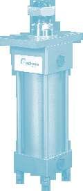
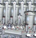
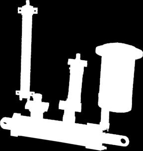
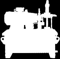
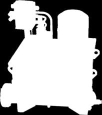
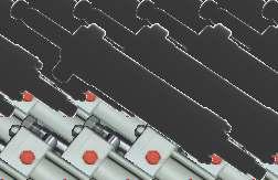
6 Achieve Series Hydraulic Cylinders Heavy Duty Hydraulic Cylinder For press application Heavy Duty Hydraulic Cylinder For scissor lift application and many more 0 Compact Hydraulic Cylinder 2 Pressure : Up to 1kg/cm Hydraulic Cylinder 2 Pressure : Up to 1kg/cm Round Front Flange Tie-rod Type Hydraulic Cylinder 2 Pressure : Up to 2kg/cm


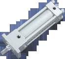
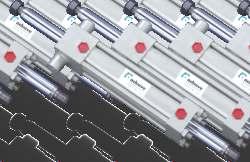
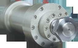
7 hydraulics & pneumatics A range of Hydraulic Cylinders Adjustable Center Trunnion Mounting Hydraulic Cylinder 2 Pressure : Up to 1kg/cm Welded Type Hydraulic Cylinder 2 Pressure : Up to 2kg/cm Heavy Duty High Pressure Hydraulic Cylinder 2 Pressure : Up to 0kg/cm 07


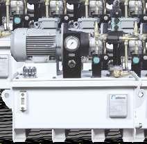


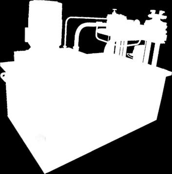
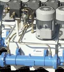
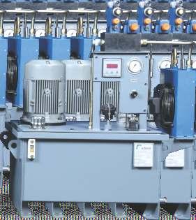
8 Achieve Series Power Pack Units Press applications With air-cooled heat exchanger Compact design power pack With Yuken components With water-cooled heat exchanger 0


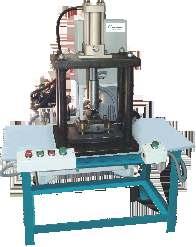


9 hydraulics & pneumatics With Rexroth components With accumulator and pressure switch Hydraulic Press Hydraulic Punching Machine Pneumatic Cutting Machine 09
 Single rod Double rod Differential cylinder The ratio between the cylinder section and the")

10 Symbols Denomination Applications Symbol Single acting cylinder The fluid pressure is applied in one sense only (forward stroke) Back stroke: by undefined force By means of a spring Double acting cylinder The fluid pressure is applied alternatively in two directions (forward and back stroke) Single rod Double rod Differential cylinder The ratio between the cylinder section and the ring section of the piston near the rod is essential for the cylinder operation Double rod Cylinder with non-adjustable cushion Acting from one side only Acting from both sides Double acting telescopic cylinder Hydraulic pressure source Pipes Cylinder with several pistons which enter into each other with forward and backward movement Control pipe (straight line for simplified representations)
11 hydraulics & pneumatics Hydraulic Cylinders - Constructional Details Cylinder Body Strict quality control standards and precision manufacturing ensure that all tubes meet rigid standards of straightness, roundness and surface finish. The steel tubing is surface finished to minimize internal friction and prolong seal life. 2 Piston Rod Gland seal life is maximized by manufacturing piston rods from precision ground, high tensile carbon alloy steel, hard chrome plated and polished to 0.2µm max. Piston rods are induction case hardened to Rockwell C minimum before chrome plating, resulting in a dent-resistant surface. 3 Piston Wear-resistant cast iron piston rings are fitted as standard to 3L cylinders. Lip seal pistons are available to suit different applications. See ' Piston Seal'. All pistons are of one-piece type, and feature wide bearing surfaces to resist side loading. Long thread engagement secures the piston rod and for additional safety, the piston is secured by thread-locking adhesive and a locking pin. 4 Cover Plates Made from mild steel and constructed with sturdy design to withstand high pressure load. 5 Caps Made of mild steel, precision machined to assure perfect alignment of the piston rod and cylinder bore. Tie Rods Made from special alloy steel and are prestressed at assembly to minimize possible elongation. 7 Gland Seals A variety of piston seal options are available to suit different applications. The seal option should be specified at the time of order. Wiper Seals Made of polyurethane rubber to prevent any dust particles from entering inside. 9 Rod Seals The serrated lip seal has a series of sealing edges which take over successively as pressure increases, providing efficient sealing under all operating conditions. On the return stroke, the serrations act as a check valve, allowing the oil adhering to the rod to pass back into the cylinder. The double-lip wiper seal acts as a secondary seal, trapping excess lubricating film in the chamber between the wiper and lip seals. Its outer lip prevents the ingress of dirt into the cylinder, extending the life of gland and seals. Standard lip seals are manufactured from an enhanced polyurethane, giving efficient retention of pressurized fluid and service life of up to five times that of the traditional seal materials. Standard seals are suitable for speeds of up to 0.5m/s - special seal combinations including PTF are available for higher speed applications. Cushioning Deceleration of a load attached to the piston rod is achieved by using built-in cushions at either or both ends of the cylinder. At the head end, a cushion sleeve is fitted, while the polished cap end spear is an integral part of the piston rod. 11 Floating Cushion Bushes and Sleeves Closer tolerances - and therefore, more effective cushioning are permitted by the use of a floating cushion sleeve at the head end of the cylinder and floating cushion bush at the cap end. A specially designed cushion sleeve on bore sizes up to 1.mm (4 ) operates as a check valve. On larger bore sizes, a conventional ball check valve is used. The use of a check valve in the head and lifting of the bronze cushion bush in the cap provides minimum fluid flow restriction at the start of the return stroke. This allows full pressure to be applied over the whole area of the piston to provide full power and fast cycle times. 11


12 Achieve Hydraulics & Pneumatics Cylinder Selection Check List The following check list indicates the principal factors which should be considered while selecting a hydraulic cylinder for a particular application. Further information is available on subsequent pages. If more information is required about any aspect of a cylinder specifications, please contact our design engineers. stablish System Parameters Ø Weight to be moved and force required Ø Nominal operating pressure and range Ø Distance to be traveled Ø Average and maximum piston speed Ø Fluid medium and temperature l Mounting Style Select the appropriate style for the specific application. Ø M5 - Head Rectangular Flange Ø MP3 - Cap Mounting Fixed ye Ø MT2 - Cap Trunnion mounting Ø Tie Rod xtended Both nds Ø MX3 - Tie Rod xtended mounting Ø M - Cap Rectangular Flange Ø MP1 - Cap Mounting Fixed Trunnion Ø MT1 - Head Trunnion Mounting Ø MX2 - Tie Rod xtended Cap Mounting Ø MS2 - Side Lugs Mounting l Cylinder Bore and Operating Pressure Ø Determine the bore and system pressure required to provide the necessary force. l Piston Rod Ø Single or double rod Ø Determine the minimum rod diameter required to withstand buckling forces. Ø Is a stop tube required? Ø Select a suitable rod end and rod end thread. Ø Check pressure rating of selected cylinder and piston rod. l Piston Ø Does the seal type suit the application? l Cushioning Ø Select the cushioning requirement if applicable. l Ports Ø Select suitable ports. Ø Are they capable of the speed required? Ø Are the standard positions acceptable? l Seals Ø Select seals to suit the chosen fluid medium and temperature range. l Rod and Cap nd Accessories Ø Are rod end and/or cap end accessories required? l Operating Features Ø Air bleeds, rod end bellows, etc.


13 AHP STD Series up to 1 bar Tie Rod Type Cylinders hydraulics & pneumatics
14 AHP STD Series up to 1 bar Tie Rod Type Cylinders Types of mountings M5-Head Rectangular Flange M-Cap Rectangular Flange MS2-Side Lug Mounting MT1-Head Trunnion Mounting MT2-Cap Trunnion Mounting MT4-Intermediate Fixed Trunnion Mounting MX3-Tie Rods xtended Head Mounting MX2-Tie Rods xtended Cap Mounting Tie Rods xtended Both nds MP3-Cap Mounting Fixed ye MP1-Cap Mounting Fixed Clevis Cap Mounting Fixed ye
15 hydraulics & pneumatics Double Acting Hydraulic Cylinders Specifications n n n n n n n n Max. pressure : 1 bar Max. reciprocating speed : m/min Breakaway pressure : 3 to 5 bar Standard cushioning length : mm Single and Double rod design 0 0 Temperature Range : C to 1 C depending on seal type Seal types to suit a wide variety of operating environment Cushion available at either end Y PJ + STROK (BSP) ØB RODØ ØNA KK TG D TG A VD WH GF J ZJ + STROK ZB + STROK Basic Dimensions Dimensions Bore Rod Ø A B D GF J KK NA PJ TG WH Y ZJ 24 1/4".0 M x VD 5.0 ZB /4".0 MX1. MX1.5P /4" 4.3 MX1.5 MX1.5P /". MX1.5 MX1.5P /" 49.0 MX1.5 M27X2P M27X2P M39X2P M33X2P MX2P M42X2P M7X2P MX2P MX2P /4".0 MX3P M1X2P Note : Special orders as per customer specifications are also accepted. All dimensions in mm unless otherwise stated. 15
16 AHP STD Series up to 1 bar Tie Rod Type Cylinders Flange and Side Lugs Mountings Y F PJ + STROK (BSP) ØFB M5-Head Rectangular Flange M-Cap Rectangular Flange Y PJ + STROK F (BSP) ØSB LH R R VD WH GF J ZJ + STROK TO UO F Y PJ + STROK (BSP) ØFB VD WH GF ZJ + STROK Z + STROK J TO UO MS2-Side Lugs Mounting VD WH XS GF ZJ + STROK SS + STROK J -Sq TS US ST Dimensions Bore F FB GF J LH R SB ST TO TS UO US XS Y + Stroke PJ SS ZJ Z /4" 1/4" 1/4" 3/" 3/" 1-1/4" Note : Special orders as per customer specifications are also accepted. All dimensions in mm unless otherwise stated
17 hydraulics & pneumatics Standard Trunnion Mountings Y PJ + STROK KB F (BSP) R 3MM Ø TD VD WH XG ZJ + STROK J TC UT MT1-Head Trunnion Mounting Y F PJ + STROK (BSP) KB R 3MM Ø TD VD WH GF TC XJ + STROK UT MT2-Cap Trunnion Mounting ZJ + STROK Y PJ + STROK KB KB F (BSP) R 3MM UW Ø TD VD MT4-Intermediate Fixed Trunnion Mounting WH GF BD XV ZJ + STROK J TM UM Dimensions Bore F TD GF J XV TM UM UW WH VD XG KB BD Y TC UT 1/4" Stroke PJ XJ ZJ /4" /4" /" 3/" To be specified /4" Note : Special orders as per customer specifications are also accepted. All dimensions in mm unless otherwise stated. 0 17
18 AA AA AA AHP STD Series up to 1 bar Tie Rod Type Cylinders xtended Tie Rod Mountings BB Y F PJ + STROK (BSP) KB DD VD WH ZJ + STROK J MX3-Tie Rod xtended Head nd Y F PJ + STROK (BSP) DD TG VD WH GF TG ZJ + STROK BB MX2-Tie Rod xtended Cap nd Y PJ + STROK BB F (BSP) DD TG TG TG VD WH GF J TG Tie Rod xtended Both nds ZJ + STROK BB Dimensions Bore F BB GF J TG DD AA WH VD KB Y 1/4" 0.0 M Stroke ZJ PJ /4" 24.0 M /4" M /" 4. M /" M M M M M /4" M Note : Special orders as per customer specifications are also accepted. All dimensions in mm unless otherwise stated.
19 hydraulics & pneumatics Pivot Mountings 1. Pivot pin not supplied Y F PJ + STROK (BSP) ØCD MP3-Cap Mounting Fixed ye 2. Supplied complete with pivot pin CW CW W VD WH GF J L MR XC + STROK Y F PJ + STROK (BSP) ØCD CB VD WH GF J L MR XC + STROK MP1-Cap Mounting Fixed Clevis 3. Pivot pin not supplied Y F PJ + STROK (BSP) CX R-MS P VD WH GF J LT ZJ + STROK Cap Mounting Fixed ye XO + STROK Dimensions Bore F CB GF J CD P CW CX W VD L MR WH Y LT MS PJ + Stroke XO XC 1/4" /4" /4" /" /" /4".0 Note : Special orders as per customer specifications are also accepted All dimensions in mm unless otherwise stated.
20 AHP STD Series up to 1 bar Tie Rod Type Cylinders Head Rectangular & Cap Rectangular Flange Mountings X PJ + STROK (BSP) KB ØFB R WH VD GF ZJ + STROK J TO UO Style 1-Head Rectangular Flange Mounting Y F PJ + STROK (BSP) KB ØFB R VD WH GF ZJ + STROK J TO UO Style 2-Cap Rectangular Flange Mounting Dimensions Bore F ø FB GF J R TO UO X Y + Stroke PJ ZP ZJ 1/4" /4" /4" /" /" /4" Note : Special orders as per customer specifications are also accepted. All dimensions in mm unless otherwise stated.


21 AHP STD Series up to 1 bar Double-nded Hydraulic Cylinders-003 hydraulics & pneumatics 21
 ØFB R R VD WH GF ZB + STROK GF TO UO F Y PJ + STROK (BSP) KB ØSB LH VD WH GF SS + STROK GF -Sq TS ST ZB + STROK US VD WH GF J -Sq TO UO")

22 AHP STD Series up to 1 bar Double-nded Hydraulic Cylinders-003 Double-nded Hydraulic Cylinders-003 ZB + STROK Y PJ + STROK KB F (BSP) ØFB Head Rectangular Flange Side Lugs Mounting Adjustable Cylinder with Flange Mountings ZB + STROK Y F PJ + STROK (BSP) ØFB R R VD WH GF ZB + STROK GF TO UO F Y PJ + STROK (BSP) KB ØSB LH VD WH GF SS + STROK GF -Sq TS ST ZB + STROK US VD WH GF J -Sq TO UO Dimensions 0 Various types of mountings n Flange Mountings n Foot Mountings n Trunnion Mountings n Tie Rod xtended Mountings Ø Also available in adjustable stroke with cushioning Ø Double-ended cylinder with female threading at both ends of rods Ø Double-ended cylinder with hollow piston rod Ø Tandem type double-ended cylinder also available as per requirement Bore Rod Add Stroke Ø No. mm Ø ZB PJ SS Add 2 X Stroke ZJ Bore Rod Add Stroke Add 2 X Stroke Ø No. mm Ø ZB PJ SS ZJ All dimensions in mm unless otherwise stated.

23 AHP STD Series up to 0 bar Heavy Duty Cylinders-004 hydraulics & pneumatics 23
24 AHP STD Series up to 0 bar Heavy Duty Cylinders Bore dia mm to 0mm, Stroke lengths up to 2,0mm for pressures up to 3kg/cm Round nd Cylinder Bore: Ø to 0mm Stroke length: Up to mm 2 Pressure: Up to 2kg/cm 'L' NOS.HOLS 'OF 'M' DIA AT 'N' PCD. FOR MOUNTING ØJ ØH ØG F I 'O' BSP. PORTS ' P ' TI RODS 'Q' DIA AT 'R' PCD ØK Dimensions Pressure Rating : 0 kg/cm 2 A B C D1 STROK+ D Bore A B C D D1 F G H I J K L M N O P Q R Tonnage at 2 1 kg/cm Mx1.5P Mx1.5P M27x2P M39x2P Mx2P M7x2P Mx2P M1x2P M1x2.5P M1x3P /4" 3/" n n n n Piston and piston rod are supported with replaceable self-lubricating bronze fined PTF bearings which provide accurate and smooth frictionless movement. nd covers are all fabricated and are of robust design to withstand heavy forces. Cold phosphatizing is done for rust prevention prior to painting. Wide varietites of mounting styles are available. Tie rod design makes the cylinder rugged and maintenance easier. n Inspection : Hydrostatic pressure testing of all hydraulic cylinders at maximum working pressure for leakages and guaranteed performance. n Optional piston rod and threads may be offered on request. n For special cylinders like double-ended cylinders, stroke adjustment cylinders and cylinders for mobile application, please contact our Sales Department. I 'O' BSP. PORTS 'P' TI RODS 'Q' DIA AT 'R' PCD Clevis nd Cylinder ØL Bore: Ø to 0mm Stroke length: Up to mm 2 Pressure: Up to 2kg/cm ØK ØH ØG F ØK R-M N A B C D1 STROK+ D J Dimensions 2 Pressure Rating : 0 kg/cm Bore A B C D D1 F G H I J K L M N O P Q R Tonnage at 2 1 kg/cm Mx1.5P Mx1.5P M27x2P M39x2P Mx2P M7x2P Mx2P M1x2P M1x2.5P M1x3P Note : Special orders as per customer specifications are also accepted /4" 3/" All dimensions in mm unless otherwise stated. 24


25 AHP Series MD up to 3 bar Mill Duty Type Cylinders-004 hydraulics & pneumatics


26 AHP Series MD up to 3 bar Mill Duty Type Cylinders-004 Cylinders designed for extreme conditions Mill type cylinders are designed for applications even under extreme conditions. Ø Service-friendly modular system Ø Various types of mounting Ø Interchangeability, thanks to standardization Ø Industry-specific and project-related cylinders on enquiry Heavy Duty Mill Type Cylinder Series 1X/2X Features Ø Nominal pressure : 2 bar Ø Piston Ø : to 0mm Ø Piston rod Ø : to 2mm Ø Mounting types : Ø Max. stroke length : 00mm Ø Max. stroke speed : 0.5m/s ISO Mill Type Cylinder Series 1X Features Ø Nominal pressure : 2 to 3 bar Ø Piston Ø : to 0mm Ø Piston rod Ø : to 2mm Ø Mounting types : Ø Max. stroke length : 00mm Ø Max. stroke speed : 0.5m/s 2 Note : Special orders as per customer specifications are also accepted. For detailed information of cylinder or to order, contact our Sales Department.
27 hydraulics & pneumatics ISO - Front Circular Flange Mounting - Style MF3 Ordering code AHP - MD - MF2 - Bore x Rod x Stroke Hydraulic Cylinder Specifications Bore ØBmm Stroke < 0 ±1mm Rod Rod Ømm Hardchrome Plated µ thk Mounting Front Circular Flange MF3 Mounting Working pressure 1 bar Design Mill Duty Double Acting Max. speed 0.5m/sec. Test pressure 2 bar Medium Hydraulic Mineral Oil Y ØJ P " BSP PORT VD ØD ØB f BOR Ø KK ROD Ø GG ØB f A ZJ+STROK ±1 F WH `L' NOS. HOLS OF `M' DIA AT `N' PCD. FOR MOUNTING Dimensions Bore dia Rod dia Rod thd Thd lg Port Spigot Dist Spigot Mfg hole Mfg hole Flange nd port Gland Cyl OD Hole nos. OD Pcd port H GG f KK A "BSP B f WH Width VD Ø N ±0.2 M J F P Y ØD L Mx1.5 Mx1.5 Mx1.5 Mx1.5 Mx1.5 M27x2 M27x2 M33x2 M33x2 M42x2 M42x2 M4x2 M4x2 Mx3 Mx3 Mx3 Mx3 Mx3 Mx3 2 1 M1x Note : Special orders as per customer specifications are also accepted /" 3/" 1-1/4" 1-1/4" 1-1/4" 1-1/4" Total lg ZJ All dimensions in mm unless otherwise stated. 27
28 AHP Series MD up to 3 bar Mill Duty Type Cylinders-004 ISO - Rear Circular Flange Mounting - Style MF4 Ordering code AHP - MD - MF4 - Bore x Rod x Stroke Hydraulic Cylinder Specifications Bore ØBmm Stroke < 0 ±1mm Rod Rod Ømm Hardchrome Plated µ thk Mounting Rear Circular Flange MF4 Mounting Working pressure 1 bar Design Mill Duty Double Acting Max. speed 0.5m/sec. Test pressure 2 bar Medium Hydraulic Mineral Oil P " BSP PORT Y ØJ ØD BOR Ø KK ROD Ø GG ØB f V A F ZP+STROK ±1 WF `L' NOS. HOLS OF `M' DIA AT `N' PCD. FOR MOUNTING Dimensions Bore dia Rod dia Rod thd Thd lg Port Spigot Dist Spigot Mtg hole Mtg hole Flange nd port Gland Cyl OD Hole nos. OD Pcd port H GG f KK A "BSP B f WF V Ø N ±0.2 M J F P Y ØD L Mx1.5 Mx1.5 Mx1.5 Mx1.5 Mx1.5 M27x2 M27x2 M33x2 M33x2 M42x2 M42x2 M4x2 M4x2 Mx3 Mx3 Mx3 Mx3 Mx3 Mx3 2 1 M1x Note : Special orders as per customer specifications are also accepted /" 3/" 1-1/4" 1-1/4" 1-1/4" 1-1/4" Total lg ZP All dimensions in mm unless otherwise stated.
29 hydraulics & pneumatics ISO - Rear Pivot Mounted Hydraulic Cylinders with Spherical Bearing - Style MP Ordering code AHP - MD - MP - Bore x Rod x Stroke Hydraulic Cylinder Specifications Bore ØBmm Stroke < 0 ±1mm Rod Rod Ømm Hardchrome Plated µ thk Mounting Rear Pivot Mounting MF Working pressure 1 bar Design Mill Duty Double Acting Max. speed 0.5m/sec. Test pressure 2 bar Medium Hydraulic Mineral Oil ØD ØCX G-CX-S-2RS P " BSP PORT Y ØD BOR Ø KK ROD Ø GG ØB f MR V A X -0.2 L Min XO+STROK ±1 WF Dimensions Bore dia H Rod dia Rod thd Thd lg Port Spigot Dist Spigot Clevis Bearing Clevis nd port Gland Cyl OD Clevis thk OD dist dia radius port GG f KK A "BSP B f WF V L min CX MR P Y ØD X Mx1.5 Mx1.5 Mx1.5 Mx1.5 Mx1.5 M27x2 M27x2 M33x2 M33x2 M42x2 M42x2 M4x2 M4x2 Mx3 Mx3 Mx3 Mx3 Mx3 Mx /" 3/" 1-1/4" 1-1/4" 1-1/4" 1-1/4" M1x Note : Special orders as per customer specifications are also accepted Total lg XO All dimensions in mm unless otherwise stated.
30 AHP Series MD up to 3 bar Mill Duty Type Cylinders-004 ISO - Side Lugs Mounting - Style MS2 Ordering code AHP - MD - MS2 - Bore x Rod x Stroke Hydraulic Cylinder Specifications Bore ØBmm Stroke < 0 ±1mm Rod Rod Ømm Hardchrome Plated µ thk Mounting Side Lugs Mounting MS2 Working pressure 1 bar Design Mill Duty Double Acting Max. speed 0.5m/sec. Test pressure 2 bar Medium Hydraulic Mineral Oil ØD P " BSP PORT Y ØSBx4Nos Thru ØD ØB f BOR Ø KK ROD Ø GG ØB f ST LH ±0.5 A TS ±0.5 US S SS+ STROK ± 1 ZJ+STROK ±1 S XS ±0.5 V WF Dimensions Bore dia Rod dia Rod thd Thd lg Port Spigot Dist Spigot Side lugs Mtg. details nd port Gland Cyl OD Total lg OD port H GG f KK A "BSP B f WF V TS ±0.5 US LH ±0.5 ST ØSB SS ±1 XS ±0.5 S P Y ØD ZJ Mx1.5 Mx1.5 Mx1.5 Mx1.5 Mx1.5 M27x1.5 M27x1.5 M33x1.5 M33x1.5 M42x1.5 M42x1.5 M4x1.5 M4x1.5 Mx1.5 Mx1.5 Mx1.5 Mx1.5 Mx15 Mx M1x Note : Special orders as per customer specifications are also accepted /" 3/" 1-1/4" 1-1/4" 1-1/4" 1-1/4" All dimensions in mm unless otherwise stated.
31 hydraulics & pneumatics ISO - Intermediate Trunnion Mounting - Style MT4 Ordering code AHP - MD - MT4 - Bore x Rod x Stroke Hydraulic Cylinder Specifications Bore ØBmm Stroke < 0 ±1mm Rod Rod Ømm Hardchrome Plated µ thk Mounting Intermediate Trunnion Mounting MT4 Working pressure 1 bar Design Mill Duty Double Acting Max. speed 0.5m/sec. Test pressure 2 bar Medium Hydraulic Mineral Oil P " BSP PORT T Y ØD R-3 ØD ØB f BOR Ø KK ROD Ø GG ØB f TD f A XV ±1 V WF TM ±0.5 UM ZJ+STROK ±1 Dimensions Bore dia Rod dia Rod thd Thd lg Port Spigot OD Dist Spigot Trunnion Mtg. details Trunnion dist. nd port Gland port Cyl OD Total lg H GG f KK A "BSP B f WF V TM ±0.5 UM ØTD f T XV ±0.5 P Y ØD ZJ Mx1.5 Mx1.5 Mx1.5 Mx1.5 Mx1.5 M27x2 M27x2 M33x2 M33x2 M42x2 M42x2 M4x2 M4x2 Mx3 Mx3 Mx3 Mx3 Mx3 Mx3 M1x /" 3/" 1-1/4" 1-1/4" 1-1/4" 1-1/4" Note : Special orders as per customer specifications are also accepted. All dimensions in mm unless otherwise stated. 31
32 AHP Series MD up to 3 bar Mill Duty Type Cylinders-004 ISO - Rod nd Accessories Rear Pivot Mounted Hydraulic Cylinders with Spherical Bearing Rod eye with spherical bearing ISO 92 Rod eye with plain bearing ISO 91 C max F N C max R M BX AX min AW CH CA LF L CN CX KK b KK b Dimensions Bore Ø KK Spherical bearing part no. Plain bearing part No. AX and AW min b BX C Max CA & CH CK H9 & CN H7 F & R M h & N h L & LF Nominal force kn Mass kg Mx1.5P Mx1.5P M27x2P M33x2P M42x2P M4x2P Mx2P Mx3P Mx3P M1x4P KK B-1 1 KK B-1 1 M4 M5 M M M Mx1.P M Mx1.P M Mx1.5P Mx1.P M Mx1.5 M Mx1.5P Mx2.5P M M24x2P M27x2P Mx2P Mx2P M42x2P M4x2P M4x2P B1 1 Nuts for Rod Clevis and Rod end attachments Note : Special orders as per customer specifications are also accepted. All dimensions in mm unless otherwise stated.


33 AHP Series WC up to 1 bar Welded Type Cylinders-004 hydraulics & pneumatics 33
34 AHP series WC up to 1 bar Welded Type Cylinders-004 Front Rectangular Flange Mounting - Style M5 Ordering code AHP - WC - M5 - Bore x Rod x Stroke Hydraulic Cylinder Specifications Bore ØBmm Stroke Rod Mounting Working pressure Design Max. speed Test pressure Medium < 0 ±1mm Rod Ømm Hardchrome Plated µ thk Front Rectangular Flange ISO M5 Mounting 1 bar Welded/Double Acting 0.1m/sec. 2 bar Hydraulic Mineral Oil P '' BSP PORT Y ØFB, 4 Nos. Holes ROD ØGG ØD BOR ØB KK- Thd ROD ØGG ØB f R ±0.2 A Welding Welding VD ZJ + STROK ±1 F WH TO ±0.2 UO Dimensions Bore dia Rod dia Rod thd Thd lg Port Spigot OD Dist Spigot Mfg hole center Mfg hole Flange Tube OD Gland port nd port Total lg H GG f KK A "BSP B f WH width VD R ±0.2 TO ± Mx1.5 Mx1.5 Mx1.5 M27x2 Mx1.5 M33x2 M27x2 M42x2 M33x2 M4x2 M42x2 Mx3 M4x2 Mx3 3/" 3/" Note : Special orders as per customer specifications are also accepted. FB H UO F D Y P ZJ All dimensions in mm unless otherwise stated. 34
35 hydraulics & pneumatics Rear Female Clevis Mounting - Style MP1 Ordering code AHP - WC - MP1 - Bore x Rod x Stroke Hydraulic Cylinder Specifications Bore ØBmm Stroke Rod Mounting Working pressure Design Max. speed Test pressure Medium < 0 ±1mm Rod Ømm Hardchrome Plated µ thk Rear Female Clevis ISO MP1 Mounting 1 bar Welded/Double Acting 0.2m/sec. 2 bar Hydraulic Mineral Oil P '' BSP PORT Y MR ØD BOR ØB ØD KK- Thd ROD ØGG ØB f CD H A L Welding ZJ + STROK ±1 VD W CB -0.2 CB +0.2 CB -0.2 Dimensions Bore dia Rod dia Rod thd Thd lg Port Spigot OD Spigot Dist Hole Radius MP1 MP1 Rod extn Tube OD Gland port nd port Total lg B H GG f KK A "BPS B f width VD L CD-H MR CB-02 CW-02 W D Y P ZJ Mx1.5 3/" Mx1.5 3/" Mx M27x Mx M33x M27x M42x M33x M4x M42x Mx M4x Mx Note : Special orders as per customer specifications are also accepted. All dimensions in mm unless otherwise stated.
36 AHP series WC up to 1 bar Welded Type Cylinders-004 Rear Male Clevis Mounting - Style MP3 Ordering code AHP - WC - MP3 - Bore x Rod x Stroke Hydraulic Cylinder Specifications Bore ØBmm Stroke Rod Mounting Working pressure Design Max. speed Test pressure Medium < 0 ±1mm Rod Ømm Hardchrome Plated µ thk Side Lugs Mounting MS2 1 bar Mill Duty Double Acting 0.5m/sec. 2 bar Hydraulic Mineral Oil P '' BSP PORT Y MR ØD BOR ØB ØD KK- Thd ROD ØGG ØB f CD H A L Welding _ ZJ + STROK +1 VD W SW -0.2 Dimensions Bore dia Rod dia Rod thd Thd lg Port Spigot OD Spigot Dist Hole r Radius MP3 Rod extn Tube OD Gland port nd port Total lg H GG f KK A "BSP B f width VD L CD-H MR SW-02 W D Y P ZJ Mx1.5 3/" Mx1.5 3/" Mx1.5 1 M27x2 1 Mx1.5 0 M33x2 0 M27x M42x M33x M4x M42x Mx M4x Mx Note : Special orders as per customer specifications are also accepted. All dimensions in mm unless otherwise stated.
37 hydraulics & pneumatics Rear Clevis with Spherical Bearing Mounting - Style MP5 Ordering code AHP - WC - MP5 - Bore x Rod x Stroke Hydraulic Cylinder Specifications Bore ØBmm Stroke < 0 ±1mm Rod Rod Ø mm Hardchrome Plated µ thk. Mounting Rear Clevis with Spherical Bearing Mounting Working pressure 1 bar Design Welded/Double Acting Max. speed 0.2m/sec. Test pressure 2 bar Medium Hydraulic Mineral Oil P '' BSP PORT Y ØCX G-CX-S-2RS ØD BOR ØB ØD KK - Thd ROD Ø GG ØB f MS A LT Welding XO - STROK ± 1 VD W P -0.2 X Dimensions Bore dia Rod dia Rod thd Thd lg Port Spigot OD Spigot B H GG f KK A "BPS B f width VD Mx1.5 Mx1.5 Mx1.5 M27x2 Mx1.5 M33x2 M27x2 M42x2 M33x2 M4x2 M42x2 Mx3 M4x2 Mx3 3/" 3/" Note : Special orders as per customer specifications are also accepted. Dist LT Clevis thk P Bearing thk X Bearing dia CX - H7 Radius MS Rod Tube OD extn Gland port nd port W D Y P Total lg XO All dimensions in mm unless otherwise stated. 37
38 AHP series WC up to 1 bar Welded Type Cylinders-004 Side Lugs Mounting - Style MS2 Ordering code AHP - WC - MS2 -Bore x Rod x Stroke Hydraulic Cylinder Specifications Bore ØBmm Stroke < 0 ±1mm Rod Rod Ømm Hardchrome Plated µ thk Mounting Side Lugs Mounting as per ISO MS2 Working pressure 1 bar Design Welded/Double Acting Max. speed 0.2m/sec. Test pressure 2 bar Medium Hydraulic Mineral Oil P BSP PORT Y Welding ØD ØD BOR ØB KK- Thd ROD ØGG ØB f ØSB Thru Hole, 4Nos. A ST LH ±0.2 T T VD W SS + STROK ±0.5 ZB + STROK ±1 XS TS ±0.5 US Dimensions Bore B H Rod GG f Rod thd KK Mx1.5 Mx1.5 Mx1.5 M27x2 Mx1.5 M33x2 M27x2 M42x2 M33x2 M4x2 M42x2 Mx3 M4x2 Thd lg A Port "BPS 3/" 3/" Spigot OD B f Width VD Dist 1 1 Mx3 5 Note : Special orders as per customer specifications are also accepted XS CCD SS CCD TS Dist US Centre dist LH Leg thk ST Hole dia SB Leg width T Rod extn W Tube OD D Gd port Y nd port P Total lg ZB All dimensions in mm unless otherwise stated. 3
39 hydraulics & pneumatics Intermediate Trunnion Mounting - Style MT4 Ordering code AHP - WC - MT4 - Bore x Rod x Stroke (min mm) Hydraulic Cylinder Specifications Bore ØBmm Stroke < 0 ±1mm Rod Rod Ømm Hardchrome Plated µ thk Mounting Intermediate Trunnion Mounting Working pressure 1 bar Design Welded/Double Acting Max. speed 0.2m/sec. Test pressure 2 bar Medium Hydraulic Mineral Oil P '' BSP PORT Y Welding ØD r ØD BOR ØB KK - Thd ROD Ø GG ØB f ØTD f ØTD f r R VD W A TL TM ±0.5 TL XV min ±1 UM ZB + STROK (min )±1 Dimensions Bore Rod Rod thd Thd lg Port Spigot OD Width Trunnion Trun dist Rod extn Tube OD GD port nd port Total lg B H GG f KK A BSP B f VD TM ±0.5 UM TL TD f R r XV min W D Y P ZB Mx1.5 Mx1.5 Mx1.5 M27x2 Mx1.5 M33x2 M27x2 M42x2 M33x2 M4x2 M42x2 Mx3 M4x3 Mx3 3/" 3/" Note : Special orders as per customer specifications are also accepted All dimensions in mm unless otherwise stated. 39
40 AHP series WC up to 1 bar Welded Type Cylinders-004 Rod nd ye Ordering code AHP - WC - Rod ye -Bore x Rod x Stroke Grease Nipple R 'A' 'A' CH ±0.5 R ØCH Spherical Bearing G-CN-S-2RS b KK THD U-0.2 AX LF SCTION - 'A-A' Dimensions Bore dia Rod dia Rod thd Thd lg Thick Radius Dist Bearing ID ye thick Dist Width B H GG f KK AX b R CH ±0 5 CN U-0 2 LF Mx1.5 Mx1.5 Mx1.5 M27x2 Mx1.5 M33x2 M27x2 M42x2 M33x2 M4x2 M42x2 Mx3 M4x2 MX3 MX3 MX Note : Special orders as per customer specifications are also accepted All dimensions in mm unless otherwise stated.
41 hydraulics & pneumatics AH P STD Adaptor As per ISO Standards ØD A A Ød G 'BSP' C L SCTION - 'A-A' Dimensions Port size Stud OD Stud length Spotface dia Spotface deep G" BSP D L d+0.3 C 1/" /4" /" /4" " 3.0 Note : Special orders as per customer specifications are also accepted. All dimensions in mm unless otherwise stated. 41
42 Hydraulic Cylinders Thrust Chart Theoretical Push & Pull Force Chart Piston dia mm Operating pressure at kg/sq. cm Rod dia mm 1 1 Piston area sq. cm Rod area sq. cm Push kgf Theoretical force (at Mechanical efficiency = %) 1 Pull kgf Push kgf Pull kgf Push kgf Pull kgf Push kgf Pull kgf Note : Special orders as per customer specifications are also accepted.


43 AHP STD Series AHP-005/00/007 hydraulics & pneumatics 43


44 AHP STD series AHP-005/00/007 Block Cylinder Double Acting / Single Acting (Spring Return), Push Type N1Ø THRU HOL & 'C' BOR ØN2 x DP, 02 Nos. G1/4" BSP CLAMP PORT K G1/4" BSP Declamp Port for Double acting, Breather for Single Acting M STROK B C B Ød SW A N1 Ø THRU HOL, 2 Nos. L F H All dimensions in mm. Overall dimension tolerance ±0.5 mm Description Block cylinders are widely used in work holding fixtures and other short stroke applications. Advantages As compared to the tie rod construction cylinders, these cylinders are very compact, due to the internal construction. These cylinders are versatile, i.e. they can be mounted in many different ways. Versions Two versions are available in all models. Ø Double-acting Ø Single-acting push type with spring return Installation The cylinder can be mounted on the front side (rod side), rear side and side faces, as shown in figures. Specifications Maximum operating pressure - 0 bar Note Ø For side mounting, positive stopper should be provided to reduce the load on the clamping bolts (fig.3). Ø For the single-acting, spring return cylinder a breather is provided. It should be protected from cutting liquids and coolants. Ø For ordering the seal kit, add the prefix 's' to the part number. Figure 01 Force Push 7.5kn kn 4.5 kn Force Full A B C D F H J K M N1 N2 P SW 4.5kn M x 15 Deep kn M x Deep kn M24 x Deep Double-acting cylinder Part No Stroke ±1 L Oil Vol. Push Oil Vol. Pull Weight cc cc 1.5kg 9 cc 15 cc 2.3kg 1 cc 15 cc 2.5kg 111 cc 3 cc 3.5kg 5 cc 37 cc 9.kg 1 1 cc 93 cc.3kg Figure 02 Figure 03 Note : Special orders as per customer specifications are also accepted. Single-acting push type spring return cylinder Part No Stroke ±1 L Oil Vol. Push Spring Force Weight 15 cc 1 N 1.5kg 9 15 cc N 2.3kg 15 1 cc 0 N 2.5kg cc 2 N 3.5kg cc 4N 9.kg 1 cc 0 N.3kg All dimensions in mm unless otherwise stated. 44
45 ØD o o hydraulics & pneumatics Compact Cylinder Double Acting / Single Acting Rod nd SW H2 o STROK o DØ dø R H1 KØ THRU G BSP 2 NOS. F MIN. L 'C' BOR MØxN DP P PCD 3 HOLS FROM BOTH SIDS All dimensions in mm Overall dimension tolerance ±0.5 mm Description Compact cylinders are solid piston, double acting cylinders and are very compact in the axial direction. Force Push Force Pull Bore Ø 4.7kn 3kn kn kn kn 9kn kn kn Advantages Ø These cylinders are used where height is a constraint. Ø Mounting of the cylinder is very easy. F d M x deep 5 M x deep 5 M x deep M x deep D 5 7 Specifications G 1/" 1/" 1/4" 1/4" Ø Maximum operating pressure - 1 bar SW 17 Ø Double rod end cylinders can be available on request. H Note Ø Due to compact design, port thread depth is short. Reduce the standard connector thread length to suit the port depth. Ø For ordering the seal kit, add the prefix 's' to the part number. H2 R K M N P Application example Part No Stroke ±1 L 42 Oil Vol. Push 3 cc cc cc cc Oil Vol. Pull 2 cc 15 cc cc 15 cc Weight 0.5kg 1kg 1.5kg 2kg Part No Stroke ±1 L Oil Vol. Push cc cc 31 cc 49 cc Oil Vol. Pull 5 cc 15 cc 24 cc 37 cc Weight 0.kg 1.5kg 2kg 3.5kg Note : Special orders as per customer specifications are also accepted. All dimensions in mm unless otherwise stated.


46 AHP STD series AHP-005/00/007 Threaded Body Cylinder Single Acting (Spring Return), Push Type L 1 BLD PORT K x DP SW Ø D F Ø d Ø D1 Mx15 DP 'P' PCD, 2 Nos. Ø D1 LOCK NUT H J L All dimensions in mm Overall dimension tolerance ±0.5 mm Description Solid piston threaded body cylinder is single acting, spring return cylinder, suitable to use with hydro-pneumatic intensifier. Advantages Ø The cylinder is most simple in construction and very easy for maintenance. Ø The piston force can be directly used for clamping (fig.1) The piston force can be increased by using a clamping strap leverage (fig.2) Installation The cylinder can be mounted in two ways 1. Against front collar with thread lock nut - Front mounting Figure 01 Force Ø Bore D d D1 F G H J K M P SW 3kn 5kn kn kn kn kn kn M24x2P 1/'' 7 M Mx2P 1/'' M M M4x2P 1/4'' 9 M M Mx2P Mx2P 1/4'' 3/'' 15 M M M M Mx2P Mx2P 3/'' 3/'' M M M M With back mounting holes - Rear mounting Figure 02 Specifications Ø Maximum oil pressure 0 bar Ø Return spring back 1 bar Note Ø As the cylinder is single acting spring return, a breather is provided. It should be protected from cutting fluid and coolant. Ø Heavy extensions to piston rod can influence return stroke of the cylinder. Ø Lock nut has to be ordered separately. Ø For ordering the seal kit, add the prefix 's' to the part number. Note : Special orders as per customer specifications are also accepted. Part No. Stroke ±1 L L1 Min. Spring Force Oil Vol. Pull Weight Part No. Stroke ±1 L L1 Min. Spring Force Oil Vol. Pull Weight Part No. D2 W N 3 cc 0.kg Lock Nut (Accessory) To be ordered separately hex 49 1N 3 cc 0.5kg 4 hex N 7 cc 1kg Ø N cc 1.5kg Ø 1 41N cc 2kg Ø D2 1 1.N cc 3.5kg Ø w N 4 cc 4.kg N 179.0N cc 0.7kg 2 77 cc 1.kg 5 2.5N 31 cc 2kg 1 3 4N cc 3kg N 0 cc 5.2kg 1 5.7N cc.5kg Ø1 15 All dimensions in mm unless otherwise stated. 4

47 AHP STD Series-007 Hydraulic Telescopic Cylinders l Single Acting/Double Acting 2, 3, 4 Stages hydraulics & pneumatics 47

48 AHP STD Series-007 Hydraulic Telescopic Cylinders Hydraulic Telescopic Cylinders Single Acting/Double Acting 2, 3, 4 Stages Introduction Telescopic cylinders are specially designed hydraulic cylinders that provide an exceptionally long output travel from a very compact retracted length. Typically, the collapsed length of a telescopic cylinder is % to % of the fully extended length depending on the number of stages. Ø This feature is very special for machine design engineers when a conventional single-stage rod-style actuator does not fit in an application to produce the required output stroke. Ø Telescopic cylinders are usually powered by hydraulics, but some special light duty designs are powered by compressed air. Ø Telescopic cylinders are referred to as single-stage telescopic cylinders and multi-stage telescopic cylinders. A common application for telescopic cylinders on a construction site is that of the dumping on a dump truck. In order to empty the load of gravel completely, the dump body must be raised to an angle of about º. To accomplish this long travel with a conventional hydraulic cylinder is very difficult considering that the collapsed length of a single-stage rod cylinder is approximately 1% of its output stroke. Ø It would be very challenging for the design engineer to fit the single-stage cylinder into the chassis of the dump truck with the dump body in the horizontal rest position. This task is easily accomplished, however, using a telescopic style multi-stage cylinder. Design and Technical Terminology Showing the telescopic principle, an object collapsed (top) and extended (bottom), providing more reach. Telescopic cylinders are designed with a series of steel tubes of progressively smaller diameters nested within each other. The largest diameter sleeve is called the main or barrel. The smaller inner sleeves are called the stages. The smallest stage is often called the plunger. The cylinders are usually mounted in machinery by pivot mounts welded to the end or outer body of the barrel as well as on the end of the plunger. Telescopic cylinders can be built with as many as stages. Six stages seem to be a practical design limit as stability problems become more difficult with larger numbers of stages. Telescopic cylinders require a careful design as they are subjected to large side forces especially at full extension. The weight of the steel bodies and the hydraulic oil contained within the actuator create moment loads on the bearing surfaces between stages. These forces, combined with the load being pushed, threaten to bind or even buckle the telescopic assembly. Sufficient bearing surfaces must only be used in machinery as a device for providing force and travel. Side forces and moment loads must be minimized. Telescopic cylinders should not be used to stabilize a structural component. Telescopic cylinders are often limited to a maximum hydraulic pressure of psi. This is because the outward forces produced by internal hydraulic pressure tend to expand the steel sleeve sections. Too much pressure will cause the nested sleeves to balloon outward, bind the mechanism and stop moving. The danger exists that a permanent deformation of the outer diameter of a sleeve could occur, thus ruining a telescopic actuator. For this reason, care must be taken to avoid shock pressures in a hydraulic system using telescopic cylinders. Often such hydraulic systems are equipped with shock suppressing components such as hydraulic accumulators to absorb pressure spikes. 4
49 hydraulics & pneumatics Hydraulic Telescopic Cylinders Single Acting/Double Acting 2, 3, 4 Stages Basic Design - Types of Telescopic Cylinders Telescopic cylinders can usually be classified into two basic designs: Single acting and double acting. A number of other special designs also exist including a hybrid single / double acting design and a constant speed, constant thrust design. Single Acting Single acting telescopic cylinders are the simplest and most common design. As with a single acting rod style cylinder the single acting telescopic cylinder is extended using hydraulic pressure, but retracts using external forces when the hydraulic pressure is removed and relieved to the reservoir. This external retraction force is usually gravity acting on the weight of the load. This external weight must obviously be sufficient to overcome the friction and mechanical losses within the machine design even after the work portion of the machine cycle has been accomplished. In the example above of the dump truck, the weight of the dump body now raised at an angle of º, but empty of the load, must be enough to force the un-pressurized hydraulic fluid out of the cylinder and cause it to retract to the fully collapsed position. Double Acting A double acting cylinder is extended and retracted using hydraulic pressure in both directions. Double acting telescopic cylinders are thus much more complex in design than the single acting type. This additional complexity is due to the requirement of adding retracting piston faces to all of the cylinder stages and the difficulty in supplying pressurized fluid to the retraction pistons of the intermediate stages. To accomplish the double acting feature, additional hydraulic seals are added to internally seal off the individual stages. In addition, internal oil passageways are machined, so that as each stage completes retracting, an oil passage is opened to supply the next stage with pressurized fluid to retract. Thus, a double acting telescopic actuator usually retracts starting from the smallest diameter stage to finish with the largest stage retracting lastly. Because the seals used to accomplish this must pass over these internally machined fluid transfer holes, the seals are usually made from hard materials to resist wear and abrasion. They are often iron rings or glass reinforced nylon seals. The extension and retraction fluid supply ports on double acting telescopic cylinders are usually located at the opposite ends of the cylinder's assembly. The extension port is mounted at the base of the outer barrel and the retraction port is mounted in the end of the plunger section. This can, in some applications, prove to be very difficult to connect with hydraulic hoses due to the distance between these ports at full extension. In such a circumstance, both ports can be located in the barrel. An internal passageway must be fitted however, so that the retracting fluid is supplied to the plunger section at full extension. This special passageway is in itself a telescopic assembly that extends with the cylinder and is outfitted with seals on the various stages. This additional complexity makes double acting telescopic cylinders very expensive. They are usually custom-designed for each application. Typical applications of double acting telescopic cylinders include the packer-ejector cylinders in garbage trucks and transfer trailers, horizontal compactors, telescopic excavator shovels and roll-on/roll-off trucks. In all of these applications, the cylinder operates near horizontally and thus is usually not available to retract the actuator. A double acting design is, therefore, required to both push and pull the telescoping mechanism. Care must be taken when controlling most double acting telescopic cylinders. The effective retraction area is often much less than the extension area. Thus, if the hydraulic fluid return line is blocked during extension, a pressure-intensifying effect can occur, causing seal failure or even causing the metal sleeve to balloon outward. The cylinder could thus be rendered unable to retract because of failed seals or jam in position due to binding. Another problem can occur if a double acting telescopic cylinder encounters a load that pulls on the actuator during extension such as when a tilting load goes over center and opens the cylinder beyond the internal volume of the hydraulic oil. When the piston face catches up again and strikes the oil column a pressure spike occurs which can damage the actuator. Single/Double Acting Combination In some unique applications, a single acting telescopic cylinder is adequate to accomplish the work except for one stage that is required to be double acting. An example of this is erecting the most of a large mobile drilling rig. The mast is erected to the vertical position using a telescopic cylinder. However, to lower the mast gravity is not available for the initial tilt back from the vertical position. Thus, the plunger stage only of the telescopic actuator is equipped as a double acting cylinder to provide the initial force to pull the mast back from vertical. Once the tilt back has been initiated, then gravity takes over and supplies the force to complete the full cylinder retraction. The remaining stages, therefore, are single acting. This special combination is much less complex and much less costly than using an entirely double acting design. Constant Thrust Constant Speed In some applications, a telescopic cylinder is required to extend with a constant force or constant speed. To accomplish this, the cylinder is designed so that all the stages extend at the same time. This can also be accomplished in a double acting design by matching the extension and retraction areas of the pistons on all the stages. 49
50 Achieve Hydraulics and Pneumatics Piston Rod Sizes & Stop Tube Piston Rod Sizes and Stop Tube Piston Rod Size Selection The selection of a piston rod for thrust (push) conditions requires the following steps to be carried out: Ø Determine the type of cylinder mounting style and rod end connection to be used. Consult the Stroke Factor table and determine which factor corresponds to the application. Ø Using the appropriate stroke factor, determine the 'basic length' from the equation : Basic Length = Net Stroke Factor (The graph is prepared for standard rod extensions beyond the face of the gland retainers. For rod extensions greater than standard, add the increases to the net stroke to arrive at the 'basic length'.) Ø Calculate the load imposed for the thrust application by multiplying the full bore area of the cylinder by the system pressure, or by referring to the Push and Pull Force charts Ø Using the graph below, look along the values of 'basic length' and ' thrust' as found in 2 and 3 above, and note the point of intersection. Stop Tube Stop tubes prevent the cylinder from completing its full stroke, to provide a spread between the piston and the rod bearing at full extension. Note that stop tube requirements differ for fixed and pivot mounting cylinders. The required length of stop tube, where necessary, is read from the vertical columns on the right of the graph by following the horizontal band within which the point of intersection lies. If the required length of stop tube is in the region labeled consult factory, please supply the following: Ø Ø Cylinder mounting style Rod end connection and method of guiding load Ø Bore required, stroke, length of rod extension. Ø Mounting position of cylinder. (Note if at an angle or vertical and specify the direction of the piston rod.) Ø Operating pressure of cylinder, if limited to less than the standard pressure for the cylinder selected. Note - When considering the use of long stroke cylinders, the piston rod should be of sufficient diameter to provide the necessary column strength. The correct piston rod size is read from the diagonally curved lines labeled Rod Diameter above the point of intersection. Pistion rod selection chart Rod Diameter(mm) Recommended length of stop tube(mm) Basic length(mm)-log scale Ø.7 Ø15.9 Ø.4 Ø34.9 Ø. Ø44.5 Ø.5 Ø7.2 Ø1. Ø.9 Ø9.7 Ø Fixed mounting No stop tube required Pivot mounting Thrust(KN)-log scale Consult Factory


51 hydraulics & pneumatics Optional Features Air Bleeds The option of bleed screws, illustrated below, is available at either or both ends of the cylinder, at any position except in the port face. The selected positions should be shown in the order code. Stroke Limiters L K Seal J Wrench Square Where absolute precision in stroke length is required, a screwed adjustable stop can be supplied at the cap end. Several types are available - the illustration shows a design suitable for infrequent adjustment of an uncushioned cylinder. Please contact the factory, specifying details of the application and the adjustment required. Bore dia B H Rod Locking Device J K min. These units provide positive locking of the piston rod. They require hydraulic pressure to release, while loss of pressure causes the clamp to operate, allowing them to be used as a failsafe device. Please consult the factory for further information. L max advise whether the spring is required to extend or return the piston rod. On spring-return cylinders, it is recommended that tie rod extensions be specified on the cylinder end in which the spring is located to allow the spring to be 'backed-off' until compression is relieved. Tie rod nuts should be welded to the tie rods at the opposite end of the cylinder, to further assure safe disassembly. Please consult the factory when ordering spring-return cylinders. Multiple Stroke Positioning To obtain linear force in one plane with controlled stopping at intermediate points, several designs are available. For three stopped positions, it is a common practice to mount two standard single rod Style H cylinders back-to-back, or to use through-tie rods. By extending or retracting the stroke of each cylinder independently, it is possible to achieve three positions at the piston end. An alternative technique is to use a tandem cylinder with an independent piston rod in the cap section. Please consult the factory for further details. Rod nd Bellows Unprotected piston rod surfaces which are exposed to contaminants with air hardening properties should be protected by rod end bellows. Longer rod extension are required to accommodate the collapsed length of the bellows. Please consult the factory for further information. Metallic Rod Wipers Metallic rod wipers replace the standard wiper seal, and are recommended where dust, ice or splashing might damage the wiper seal material. Metallic rod wipers do not affect cylinder dimensions. Position Switches These can be fitted to give reliable end of stroke signals. Position Feedback Linear position transducers of various types are available for AHP series cylinders. Please consult the factory for further details. Single Acting Cylinders Standard AHP series cylinders are of the double acting type. They are also suitable for use as single acting cylinder, where the load or other external force is used to return the piston after the pressure stroke. Cast iron piston rings should not be used with single acting cylinder. Spring-Return, Single Acting Cylinders Series AHP single acting cylinders can be supplied with an internal spring to return the piston after the pressure stroke. Please supply details of load conditions and friction factors, and 51
52 AHP Series Hydraulic Cylinders How to order Ordering details of AHP Series Hydraulic Cylinders AHP HD 0 K F C L C L T 00 Series Type of duty Bore dia Rod dia Stroke Mounting style Cushion head Temperature Piston seal Working pressure Ports Modification Heavy duty-hd Mill duty-md Single acting cylinder Double acting cylinder Specify bore dia in mm,,,,,,1, 1, 0 In mm 0, 0, 0, 0, 0,, 00, in mm Use K only if a double & single acting cylinder is required. M = Basic M5 = Head rectangular flange M = Cap rectangular flange MS2 = Side lug mounting MT1 = Head trunnion mounting MT2 = Cap trunnion mounting MT4 = Intermediate fixed trunnion mounting Mx3 = Tie rods ext. head mounting Mx2 = Tie rods ext. cap = Tie rods ext. both ends MP3 = Cap mounting fixed eye MP1 = Cap mounting fixed clevis cap mounting fixed eye with bearing X other = Use c only if head and cushion is required CB-Cushioned at both end NC-Non-cushioned CC-Cap end cushioned CH-Head end cushioned L = Low up to - C M = Medium up to - 1 C H = High up to - 2 C C = Ring packed piston L = Lip seal piston K = Hi load piston F = Low friction S = Spring loaded PTF piston seals 1 = Magnetic piston, stainless steel cylinder body, single bi-directional piston seal 2 = Magnetic piston, carbon steel body, single bi-directional piston seal L = Low up to bar M = Medium up to 1 bar H = High up to 3 bar T = SA straight thread O-ring (std) U = NPT ports (dry seal pipe thread) R = BSP ports (parallel thread ISO ) P = SA 4-bolt flange ports (00psi) B = BPST ports (taper thread) G = Metric thread ports Y = Metric thread ports per ISO 9 M = Used only for manifold port O-ring seal. M option must be specified (mounting modification), applies to mounting style C only. 1X Sample order: AHP / HD / / / 0 / K / M5 / GB / L / C / M / R 52


53 AHP Series Power Pack Units & Systems hydraulics & pneumatics 53

 Ø Fixed or variable")


54 AHP Series Power Pack Units & Systems Power Pack Units & Systems Ø Ø Ø 0 Achieve specializes in developing hydraulic systems from enquiry to final commissioning and after-sales service. Achieve uses only top-quality components. Achieve hydraulic power packs and hydraulic systems are fully tested and documented before delivery. Hydraulic Power Packs Features Ø Use single or three phase electric motors Ø Pressures range up to 0 bar (,000psi) Ø Fixed or variable delivery piston, vane pumps or gear Ø Cater to most fluids such as mineral oil Ø All valve configurations and operating modes supplied Ø Good availability of spares and excellent service support Hydraulic Power Packs and Systems Applications 0 Ø Ø Ø Ø Ø Ø 0 0 Ø Ø Ø Ø Special Purpose Machinery manufacturers Building material manufacturers University test equipment Foundries Maintenance of electrical power lines Production and maintenance of gas and water pipes and many more... Achieve offers Special requirement power packs Installation and commissioning of new hydraulic systems Refurbishment of existing hydraulic systems fficient, friendly service
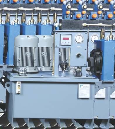
55 hydraulics & pneumatics General guidelines for Hydraulic Power Packs All Achieve Hydraulic Power Pack Units are made as per standard or our customers normally accepted requirements. High performance, compactness and easy maintenance are the main features of these Power Pack Units. The figure below shows the general layout of a Hydraulic Power Unit and the elements indicated are required in every Power Unit for proper functioning of the system. 0 0 ngineering Guidelines Ø These units are of a modular design. For further information, please contact our sales office. Commissioning Guidelines General Ø The power units supplied by us have been tested for function and performance. Changes in any form of manner to the power units are not permitted as this would also invalidate any guarantee claims. Ø Repairs may only be carried out by the manufacturer or authorized agent. No guarantee will be accepted for commissioning carried out by third parties. Commissioning Ø Only fill the pressure fluid via a filter which has the necessary retention rate. Ø Take into account the direction of rotation arrow when connecting the electric motor. 0 Ø Start the pump without load and let it displace oil without pressure for a few seconds in order to provide sufficient lubrication. Ø Never run the pump without oil. Ø If the pump, after approx seconds, does not displace oil without any bubbles, then the system has to be rechecked. Ø After the operating valves have been reached, check the pipe connection for leakage and check the operating temperature. Bleeding Ø Before commissioning, the pump housing must be filled with oil. Important Notice Ø Assembly, maintenance and servicing of the power unit must only be carried out by authorized and trained personnel. Ø The power unit must be operated within the permissible limits. When carrying out any work on the power unit, switch the system to zero pressure. Unauthorized conversions and modifications which affect the safety and function are not permitted. Ø Provide protective measures and do not remove any existing protective devices. Ø nsure that the fixing bolts are correctly fitted (take into account the prescribed tightening torque). Ø The general valid safety and accident prevention regulations must be adhered to. Ø Reservoir nominal size has to be filled with a minimum of 1 liters Part Description Reservoir Suction Strainer Baffle Plate Drain Plug Maintenance Doors Gauge Isolator Pressure Gauge Drain Line Suction Line Return Line Filter Mounting Plate Breather Cum Filter Oil level Indicator Note : Special orders as per customer specifications are also accepted. All dimensions in mm unless otherwise stated. 55


56 AHP Series Power Pack Units & Systems Power Pack Units Specifications 0 Ø Tank capacity : liters Ø Pump : Gear pump 9 lpm, at rpm Ø Motor : 3 HP, 3-phase Ø Direction Control Valve : Cetop - 3 mounting, 3 position Ø Solenoid Valves : Direct acting, puppet type Ø Operating pressure : 0 bar Ø Maximum oil pressure : 2 bar Figure -01 *HYD. CYLINDR *Bore-Ø, Rod-Ø, Stroke -1, Front Flange Mtg. *Bore-Ø, Rod-Ø, Stroke -1, Both nd Clevis Mtg. Product Description Ø This hydraulic power unit suitable to operate all clamping cylinders is parallel in clamping mode, after reaching the set pressure, which is sensed by a pressure switch, direction control valve shifts to the center position, unloading pump delivery to the tank. In case of pressure drop, the direction control valve operates to increase pressure, to the set pressure. P T A P B T A P B T A B A B P T P T P T Ø In unclamp mode, direction control valve moves to the unloading position, after the set delay. Ø The system includes all relevant electrical and mechanical accessories. Pendent with clamp / unclamp push buttons is provided along with the switch. M TANK Liters Note : Special orders as per customer specifications are also accepted. All dimensions in mm unless otherwise stated.


57 hydraulics & pneumatics Power Pack Units Specification 0 Ø Tank capacity :.5 liters Ø Pump : Radial Piston Pump, 5.0 liters/min. at rpm Ø Motor : 2hp, 3-phase rpm Ø Accumulator : 2.5 liters Ø Solenoid operated : Direction Control valve Ø Operating pressure : 1 bar Ø Maximum oil pressure : 0 bar Ø Pressure switch : 0-0 bar Circuit Diagram CLAMP CYLINDR CLAMP CYLINDR Salient Features Ø Modular construction - There are four separate manifolds,two for the top die and two for the bottom die. A Separate manifold is provided for the die lifters. All these manifolds are mounted on the base manifold, which includes pressure switches, accumulator, pressure relief valve, and check valves the tandem clamping ensures positive clamping. A P B T 5 RAIL BRIDG CYLINDR Ø The pump is put 'ON' and 'OFF' by differential pressure switches that give feedback and stop the press. Ø Accumulator is fitted to compensate leakage in case of power failure. Ø Direction control valve allows the operation of either die clamp or die lifters. M A P B T TANK Note : Special orders as per customer specifications are also accepted. All dimensions in mm unless otherwise stated.


58 AHP Series Power Pack Units & Systems We also undertake the development of special purpose hydraulic systems for unique applications. One such system has been supplied to a thermal power plant for coal transfer and conveying lines. Using this system, the hopper beneath the wagon tippler can be located / relocated to different positions to feed multiple belt conveyors. The specialties of this systems are its completely dust-free enclosure and use of flame-proof motors to avoid possibility of fire. The use of high-quality flame-proof motors suitable to work in gas group II C ensures safe working. Also, hydraulic oil is completely protected from dust contamination for which a special dust-free enclosure for the entire system is provided. We have designed manufactured and installed complete systems comprising hydraulic cylinders, power packs, piping and control panel. 5
59 hydraulics & pneumatics Notes All logos and monograms used in this catalogue are trademarks of respective companies. In keeping with our constant endeavour to meet ever-changing market needs, we reserve the right to alter or change the specifications mentioned without prior notice. 59


60 An ISO 01:0 Certified Company hydraulics & pneumatics Achieve Hydraulics & Pneumatics Gat No. 17, Chikhali-Talawade Road, Shelar Wasti, Chikhali, Pune 4 1 INDIA Mobile : , Tel. : , 04/5 Fax : mail : response@achievehydraulics.com Authorised Dealer Technical changes reserved copyright Achieve Hydraulics & Pneumatics. Achieve-01/0/2k
HEAVY DUTY PNEUMATIC CYLINDERS
 HEAVY DUTY PNEUMATIC CYLINDES Features: Conforms to ISO:30 standard. Double Acting, with adj. cushioning at both ends. Sizes: Ø, Ø, Ø, Ø, Ø, Ø0, Ø1, Ø0, Ø0 & Ø0. : Other bore sizes on request Seamless
V160C. Mould Hydraulic Systems. Hydraulic cylinders-iso 6020/2 compact 160 bar V160C
 V160C Mould Hydraulic Systems Hydraulic cylinders-iso 6020/2 compact 160 bar V160C V160Ccat.GB01-2006 Hydraulic cylinders-iso 1 2 Chrome-plated steel rod, hardened or tempered and polished. Thickness of
ISO 6020/2 industricylindre Industrial cylinders
 According to ISO 6020/2 1991 DIN 24554, compact series 160 bar Working pressure up to 21 Mpa Maximum pressure 25 Mpa Working temperature 20 to 80 C Stroke tolerance 0 to 1.2mm for strokes up to 1000mm,
HYDRAULIC HEAVY DUTY
 Catalog #HHD-16 12/16 HYDRAULIC HEAVY DUTY Series HHD 3000 PSI RATED 10-25-16 WARNING IMPROPER SELECTION, IMPROPER USE OR FAILURE OF THE PRODUCTS AND/OR SYSTEMS DESCRIBED HEREIN CAN CAUSE PROPERTY DAMAGE,
PURAKAL SERIES 100 TABLE OF CONTENTS
 TABLE OF CONTENTS How to Order Cylinder......................... Repair Kit......................... Seal Kit......................... Warranty......................... Parts List.........................
AS/ASH SERIES ALUMINUM PNEUMATIC AND HYDRAULIC CYLINDERS... 6
 AS/ASH SERIES ALUMINUM PNEUMATIC AND HYDRAULIC CYLINDERS............. 6 Section 6 8 ORDERING INFORMATION For Rod End Dimensions see back cover foldout... Basic Cylinder No Mount.0" to 4.00" For pressure
ASP Series Steel Body NFPA Cylinder Line
 Series Steel Body NFPA Cylinder Line www.numatics.com Table of Contents Series Features and Benefits 3 Standard Mounts 4 How to Order 5 Port Size Availability 6 Dimensions 7-34 Rod Ends 7 Large Bore 8
PL-2 Series Medium-Duty Industrial Hydraulic Cylinders BPL-2 PH-2 PH-3 PHX
 PL- Series Medium-Duty Industrial Hydraulic Cylinders PHX PH- PL- PH- Contents Features... Specifications / Mountings... Design Features and enefits... - Mounting Information, " to " ore Sizes... 8- Mounting
Hydraulic cylinders Tie rod design. Type CD70 / CG70. Features. Contents
 Hydraulic cylinders Tie rod design Type CD / CG Features types of mounting Piston Ø (ØAL)... mm Piston rod Ø (ØMM) 12... 1 mm Stroke length up to 3 m Project planning software Interactive Catalog System
Hydraulics H Y D R A U L I C S
 Hydraulics H Y D R A U L I C S Guarantees from a leading... BUT DIFFERENT COMPANY Companies tend to communicate values such as excellence, quality, commitment, honesty or customer service... At AirControl
NFPA Double acting imperial cylinders
 > > Ø 4... 8 > > Adjustable captive cushion needle > > Constructed of the finest materials > > Magnetic piston standard > > Wide temperature range > > Shock and vibration tested to N 61373, Category 1,
AIR CYLINDER Series A23, A24
 A23 - Magnetic A24 - Non-magnetic Double Acting s (Square type) Ø32-125 mm As per ISO 15552 / VDMA 24562 standards. Features Adjustable cushioning at both ends with elastomer pads Wide varieties of mountings
SERIES MH (NFPA) CYLINDER
 CYLINDER") MH SERIES TAB 58 Floating Rod Bushing SELF ALIGNMENT FEATURE Rod Bushing is designed to float.002 to improve bearing surface alignment. SERIES MH (NFPA) CYLINDER Reduces cylinder drag and erratic operation
MH SERIES TAB 58 Floating Rod Bushing SELF ALIGNMENT FEATURE Rod Bushing is designed to float.002 to improve bearing surface alignment. SERIES MH (NFPA) CYLINDER Reduces cylinder drag and erratic operation
ZBD 2512 Differential Cylinder Data sheet 07.16/DS13660
 ZBD 2512 Differential Cylinder Data sheet 07./DS Description: The STORZ hydraulic cylinder series ZBD 2512 for the nominal pressure of 250 bar is replaceable with the CDH1 series. By fixing the mounting
SERIES PSI 5000 PSI NON SHOCK HYDRAULIC CYLINDER PURAKAL CYLINDERS, INC PURAKAL CYLINDERS, INC
 CYLINDERS, INC SERIES 3000 3000 PSI 5000 PSI NON SHOCK PURAKAL 1234 345 4567 6789 8901 0123 23 PURAKAL 1234567 HYDRAULIC CYLINDER PURAKAL CYLINDERS, INC P.O. Box 22038 1017 S.Danebo Ave. Eugene, OR 97402-0414
AIR CYLINDER Series A12, A13
 A12 - Non magnetic A13 - Magnetic S Double Acting ( Ø32-100 ) mm As per ISO 6431 / CETOP RP43P, RP53P standards Features Adjustable cushioning at both ends Wide varieties of mountings Low friction Long
FULL COLOR TAB #1 TA 7
 FULL COLOR TAB #1 TA 7 TA - How to Order Floating Rod Bushing SELF ALIGNMENT FEATURE Rod Bushing is designed to float.00 to improve bearing surface alignment. SERIES TA (NFPA) CYLINDER Reduces cylinder
Air Cylinders Type : ISO-6431 & VDMA-24562
 Air Cylinders Type : ISO-6 & VDMA-262 Conform to ISO: 6 & VDMA: 262 standards. Double acting, with adj. cushioning at both ends. sizes : Ø, Ø, Ø, Ø, Ø, Ø0, Ø1, Ø0 & Ø0 Profiled aluminum tube with hard
Hydraulic Cylinder NFPA Industrial Type
 Hydraulic Cylinder NFPA Industrial Type RA 7038/08.3 Replaces: 0.3 /44 Model CDT/CGT Series X Nominal pressure: Up to,500 psi maximum Table of contents Features Contents Page Duty, up to,500 psi (see chart
Miller JV Series. Medium Duty Hydraulic Cylinders. Up to 1000 PSI Bore Sizes 1" through 8" 18 Mounting Styles. Catalog M September, 2011
 Medium Duty Hydraulic Cylinders Catalog M0- September, 0 Up to 000 PSI ore Sizes " through " Mounting Styles AV Series Cylinders Up to 0 PSI Permanently Lubricated AL Series Aluminum Cylinders Up to 0
SERIES PSI OPERATING PRESSURE HEAVY HYDRAULIC DUTY CYLINDER HEAVY DUTY HYDRAULIC CYLINDER PURAKAL CYLINDERS, INC CYLINDERS, INC
 CYLINDERS, INC SERIES 2500 3000 PSI ORATING PRESSURE HEAVY DUTY HEAVY HYDRAULIC DUTY CYLINDER HYDRAULIC CYLINDER PURAKAL CYLINDERS, INC PURAKAL P.O. Box 22038 CYLINDERS, INC P.O. Eugene, Box OR 22038 97402-0414
Mobile Cylinder Div. Standard Build Series. Catalog HY /US Rev C
 Mobile Cylinder Div. Standard Build Series Catalog HY18-0014/US Rev C WARNING - USER RESPONSIBILITY FAILURE OR IMPROPER SELECTION OR IMPROPER USE OF THE PRODUCTS DESCRIBED HEREIN OR RELATED ITEMS CAN CAUSE
Metric Hydraulic Cylinders Series HMI
 Series HMI Conforms to ISO 600/ (99) or working pressures up to 0 bar Vital Technologies for Motion and Control or Cylinder Division Plant Locations See Page II. 05 As the world leader in the design and
Nominal operating pressure (continuous service) bar 160. Maximum operating pressure bar 210. Peak pressure bar 250. Maximum speed (standard) m/s 0,5
 bar 160. Maximum operating pressure bar 210. Peak pressure bar 250. Maximum speed (standard) m/s 0,5") 71 /17 ED HC2 HYDRAULIC CYLINDERS SERIES 2 ISO 62/2 (1991 EDITION) DIN 24554 DESCRIPTION Double acting cylinders constructed in compliance with ISO 62/2 (1991 edition) and DIN 24554. The compact design
71 /17 ED HC2 HYDRAULIC CYLINDERS SERIES 2 ISO 62/2 (1991 EDITION) DIN 24554 DESCRIPTION Double acting cylinders constructed in compliance with ISO 62/2 (1991 edition) and DIN 24554. The compact design
Tie-rod Cylinders, ISO 6431, ISO compliant Series 60
 Tie-rod Cylinders, ISO 6431, ISO 15552 compliant Series 60 Single or double-acting, magnetic, cushioned Standard and low friction versions ø 32, 40, 50, 63, 80, 100, 125 mm In compliance with ISO 15552
Series 83. Stainless Steel Mini Cylinder
 Stainless Steel Mini Cylinder Magnet included in 7/8 and 1-1/4 bore only in double acting cylinder THEORETICAL CYLINDER FORCE (LBS). Operating Pressures (PSI) Size Action 25 50 75 100 125 150 3/4" Out
Hydraulic cylinder, mill type
 Hydraulic cylinder, mill type RE 17338/07.13 Replaces: 07.12 1/74 Series CDH3 / CGH3 / CSH3 Component series 3X Nominal pressure 350 bar (35 MPa) Table of contents H4645_d Contents Features 1 Technical
AIR CYLINDER Series A25, A26
 A25 - Magnetic A26 - Non-magnetic S Double End Double Acting - Ø32-100 mm As per ISO 15552 / VDMA 24562 standards Features Adjustable cushioning at both ends with elastomer pads Wide varieties of mountings.
Series MH MH13 ISO MX1 ISO MX3 ISO MX2 MH12 MH10 MH36 MH35 MH42 ISO ME5 ISO ME6 ISO ME2 MH62 MH64 ISO MP1 ISO MP5 ISO MP3 MH61 MH72
 Series MH MH MH2 MH ISO MX ISO MX ISO MX2 MH MH MH ISO M ISO M ISO M2 MH MH2 MH ISO MP ISO MP ISO MP MH MH2 MH ISO MT ISO MT2 ISO MT Double Rod nd NPA MDX Milwaukee Cylinder Series MH ISO Metric Hydraulic
Description. Piston rod end. Technical data. Datasheet Type 46 Single rod cylinder according to ISO 6022 / DIN 24333
 CE CV LE MM KF MM KK Datasheet Type 46 Single rod cylinder according to ISO 6022 / DIN 24333 Description - Standard cylinder to ISO 6022, DIN 24333 - Strokes up to 2000 mm - Piston diameter: 40 320 mm
Extruded Body Cylinders, ISO 6431, ISO compliant Series 61
 1 ISO / VDMA Cylinders NORTH AMERICAN CYLINDER & ACTUATOR CATALOG > Release 8.5 Extruded Body Cylinders, ISO 6431, ISO 15552 compliant Series 61 Single or double-acting, magnetic, cushioned Standard and
AIR CYLINDER Series A75, A76
 A76 - n-magnetic A75 - Magnetic AIR CYLINDER Round s - Ø32, 40, 50 and 63 mm Double Acting with Adjustable Cushioning Features Available in magnetic and n magnetic version Adjustable cushioning at both
WST Stopper Cylinder. Series WST. Specifications. How to adjust the shock absorber. Precautions. Shock absorber replacement
 WST Stopper Cylinder Specifications Features Media Clean dry compressed air Operating Pressure Range 22 to 102 psi (1.5 to 7 Bar) Max* Pressure 145 psi (10 Bar) Operating Temperature Range 32 to 140 F
LP/LPM Series. Non-Lube Air Cylinder P1M. Tooling Plate P1M. Swing Clamp P1M. Contents E51
 Non-Lube Air Cylinder P1G C05(S) LP(M) Swing Clamp Tooling Plate Contents Features...52 Ordering Information...53 Specifications...54 Basic Dimensions...55 Mounting Options...56 Spring Data...57 Rod Options...58
HYDRO-PNEUMATICS. 1) Hydro-Pneumatic Tool De-Clamp Cylinders PCS Series ) Hydro-Pneumatic Intensifiers for Machining Centers... 1.
 Hydro-Pneumatic Tool De-Clamp Cylinders PCS Series ) Hydro-Pneumatic Intensifiers for Machining Centers... 1.") HYDRO-PNEUMATICS 1) Hydro-Pneumatic Tool De-Clamp Cylinders PCS Series... 1.310 2) Hydro-Pneumatic Intensifiers for Machining Centers... 1.330 HYDRAULIC CYLINDERS 1) LH7 Series... 2.110/1 Std. Mounting
HYDRO-PNEUMATICS 1) Hydro-Pneumatic Tool De-Clamp Cylinders PCS Series... 1.310 2) Hydro-Pneumatic Intensifiers for Machining Centers... 1.330 HYDRAULIC CYLINDERS 1) LH7 Series... 2.110/1 Std. Mounting
Hydraulic cylinders type CN - round heads with counterflanges to ISO nominal pressure 16 MPa (160 bar) - max 25 MPa (250 bar)
 - max 25 MPa (250 bar)") www.atos.com Table B80-/E Hydraulic cylinders type CN - round heads with counterflanges to ISO 600- - nominal pressure 6 MPa (60 bar) - max MPa (0 bar) SWC Cylinders Designer Software for assisted selection
www.atos.com Table B80-/E Hydraulic cylinders type CN - round heads with counterflanges to ISO 600- - nominal pressure 6 MPa (60 bar) - max MPa (0 bar) SWC Cylinders Designer Software for assisted selection
Series AHM Metric Hydraulic Cylinder
 Series AHM Metric Hydraulic Cylinder As a major supplier of pneumatic and hydraulic cylinders, Atlas Cylinders introduces the Series AHM metric hydraulic cylinder. Atlas Series AHM cylinders are designed
Pneumatic Cylinders NFPA Series
 Pneumatic Cylinders NFPA Series INDEX: General characteristics 3 Mounting styles 5 Piston rod characteristics (bore diam 25/150) 6 Single rod cylinder dimensions (bore diam 25/150) 8 Piston rod characteristics
Medium Duty 1.5 ~ 4 Bore 12 Different NFPA Mounting Options Non-Rotating Option Tandem Cylinder Option Auto Switch Capable
 N304 Air Cylinder NCA1 Series NFPA Interchangeable Medium Duty 1.5 ~ 4 Bore 12 Different NFPA Mounting Options Non-Rotating Option Tandem Cylinder Option Auto Switch Capable NFPA Interchangable Air Cylinder
2A Tie Rod Cylinders NFPA Pneumatic Cylinders for working pressures up to 18 bar. Catalogue HY /UK October 2006
 A NFPA Pneumatic Cylinders for working pressures up to bar Catalogue HY0-090/UK October 00 Catalogue HY0-090/UK Mounting Styles A Cylinder Mounting Styles The standard range of Parker A cylinders comprises
XG*-***-****-***-****
 Technical details Cylinders > piston rod cylinders > Series XL, ISO ISO 15552, 15552, double double acting acting Operating pressure Temperature range Max. stroke Medium Materials 1... 10 bar -20 C...
Hydraulic cylinders type CH - big bore sizes to ISO nominal pressure 16 MPa (160 bar) - max 25 MPa (250 bar)
 - max 25 MPa (250 bar)") www.atos.com Table B60-6/ Hydraulic cylinders type CH - big bore sizes to ISO 600- - nominal pressure 6 MPa (60 bar) - max 5 MPa (50 bar) SWC Cylinders Designer Software for assisted selection of Atos
www.atos.com Table B60-6/ Hydraulic cylinders type CH - big bore sizes to ISO 600- - nominal pressure 6 MPa (60 bar) - max 5 MPa (50 bar) SWC Cylinders Designer Software for assisted selection of Atos
Bore ø 32, 40, 50, 63, 80, 100, 125 Ports 32 = 1/8, 40/50 = 1/4, 63/80 = 3/8, 100/125 = 1/2
 6 S E R I E S Cylinders Series 6 Catalog 2006 Single, double acting, magnetic (DIN/ISO 643) Bore: ø 32, 40, 50, 63, 80, 00, 25 cushioned [ /4, 9/6, 2, 2 /2, 3 /8, 4, 5 inch approximations] The Series 6
Hydraulic cylinder Type CDL1
 Industrial Hydraulics Electric Drives and Controls Linear Motion and Assembly Technologies Pneumatics Service Automation Mobile Hydraulics RE 17 325/01.03 Replaces: 07.02 Hydraulic cylinder Type CDL1 Series
SERIES HH (NFPA) CYLINDER
 CYLINDER") HH SERIES TAB 5 Floating Rod Bushing SELF ALIGNMENT FEATURE Rod Bushing is designed to float.002 to improve bearing surface alignment. SERIES HH (NFPA) CYLINDER HH Rod Lock Reduces cylinder drag and erratic
HH SERIES TAB 5 Floating Rod Bushing SELF ALIGNMENT FEATURE Rod Bushing is designed to float.002 to improve bearing surface alignment. SERIES HH (NFPA) CYLINDER HH Rod Lock Reduces cylinder drag and erratic
ISO 6022 DIN Nominal operating pressure (continuous service) bar 250. Maximum operating pressure bar 320. Maximum speed (standard) m/s 0,5
 bar 250. Maximum operating pressure bar 320. Maximum speed (standard) m/s 0,5") 71 /112 ED HC3 HYDRAULIC CYLINDERS HCK3 HYDRAULIC CYLINDERS ATEX 94/9/CE ISO 6022 DIN 24333 DESCRIPTION Double acting cylinders constructed in compliance with ISO 6022 and DIN 24333. The materials used
71 /112 ED HC3 HYDRAULIC CYLINDERS HCK3 HYDRAULIC CYLINDERS ATEX 94/9/CE ISO 6022 DIN 24333 DESCRIPTION Double acting cylinders constructed in compliance with ISO 6022 and DIN 24333. The materials used
Series ICS and ICL Pneumatic Cylinders. Corrosion resistant stainless steel and aluminum cylinders
 Series ICS and ICL Pneumatic Cylinders Corrosion resistant stainless steel and aluminum cylinders Series ICS and ICL cylinders New generation of stainless steel and clean line cylinders. Series ICS from
Series AM/MM/WM Mill Type Cylinders
 ET AH To order this part, call Lifco Hydraulics USA Toll Free at -00-- S S ZE* SS* SW (TYP) FB THRU, () PLACES TE UF WA / EE P* ØE EE P* CD 00 M CW S Series AM/MM/WM Mill Type Cylinders Table of Contents
Tie Rods hydraulic Cylinders Catalog 2T Series - ISO 6020/2
 SMART POWER Tie Rods hydraulic Cylinders Catalog 2T Series - ISO 6020/2 Member of MOVE & POWER MOVE & POWER We design and manufacture hydraulic and pneumatic cylinders and hydraulic power units, to supply
HH SERIES: HEAVY DUTY INDUSTRIAL HYDRAULIC TRD BIMBA. company
 HH SERIES: HEAVY DUTY INDUSTRIAL HYDRAULIC TRD a BIMBA company The TRD difference... Precision machined throughout. We started in business as precision machinists. Every component is machined in a manner
RA/28000, RA/ Pneumatic Cylinders ISO 6431, VDMA and NFE Non-magnetic and Magnetic, Single Acting 32 to 100 mm
 Pneumatic Cylinders ISO 6431, VDMA 24562 and NFE 49-003-1 Non-magnetic and Magnetic, Single Acting 32 to 100 mm ugged tie rod construction Polyurethane seals ensure efficient low friction operation and
2. COMPACT CYLINDERS series STRONG (RS, RQ)
") 2. COMPACT CYLINDERS series STRONG (RS, RQ) A new series of compact cylinders for long s and heavy-duty applications standard supplied with oversized guides and rods, the first one with adjustable pneumatic
2. COMPACT CYLINDERS series STRONG (RS, RQ) A new series of compact cylinders for long s and heavy-duty applications standard supplied with oversized guides and rods, the first one with adjustable pneumatic
Aluminium tube and profile
 > Series 63 cylinders CATALOGUE > 206 Series 63 cylinders - Aluminium tube and profile New Single and double-acting, magnetic, cushioned Versions: standard, low friction, high and low temperatures ø 32,
AZ Cylinder. Specifications. Features: Features Type ISO 6431 VDMA CETOP RP43P. Ø32mm - 100mm ISO 6431 VDMA CETOP RP43P.
 Specifications Features Type ISO 6431 VDM 24562 CTOP P43P Series Z Configurations Z Double cting, Single od, Magnetic Piston, Cushions ZD Double cting, Double od, Magnetic Piston Construction Materials
Our policy is one of continued research and development. We therefore reserve the right to amend,
 Airmotor (Oscillator) with integrated switches Double acting Ø 50... 100 mm Complete functional unit for oscillating movement Conforms to ISO 6431 and VDMA 24562 Integrated 5/2 valve Frequency and speed
Tie rod cylinders, Series 523
 Electric Drives and Controls Hydralics Linear Motion and Assembly Technologies Pneumatics Service Tie rod cylinders, Series 523 Technical data Tie rod cylinders, Series 523 Grey series, 32 25 mm ( /4"-5")
Tube connection Ambient temperature range Medium temperature range. T min C +80. C T max. max. Weight (mass) kg See table
 kg See table") Cylinder Ø32-125 mm with blocking device Series DZB... Blocking reverse stroke Series DZBA... Blocking forward stroke Mountings to ISO 15552 (ISO 6431) Special versions: according to CETOP RP 53 P (Piston
Cylinder Ø32-125 mm with blocking device Series DZB... Blocking reverse stroke Series DZBA... Blocking forward stroke Mountings to ISO 15552 (ISO 6431) Special versions: according to CETOP RP 53 P (Piston
Twin Rod Non Rotate Cylinders RDV and AZ
 Twin Rod Non Rotate Cylinders RDV and AZ A range of twin rod cylinders designed for use in non rotate applications specifially suited to the handling and packaging environments. Offering a range of double
V230T. Mould Hydraulic Systems. Hydraulic cylinders - high temperature 230 bar V230T
 V230T Mould Hydraulic Systems Hydraulic cylinders - high temperature 230 bar V230T V230Tcat.GB01-2006 Hydraulic cylinders-with tie rods 1 2 3 4 5 6 7 8 9 Chrome-plated steel rod, hardened or tempered and
High Performance Repairable Pneumatic Cylinder Parker Hannifin Corporation
 High Performance Repairable Pneumatic Cylinder 219 Pneumatic ivision eatures Optional Piston Magnet Located under wear band, piston magnet is used for through-thebarrel sensors for electronic piston position
Large Bore Extruded Cylinders, ISO 6431 Series 41
 Large Bore Extruded Cylinders, ISO 6431 Series 41 Double-acting cushioned, magnetic ø160-200 (DIN/ISO 6431)»» DIN/ISO 6431 VDMA 24562»» Rolled stainless steel rod»» Adjustable cushioning Cylinders Series
SERIES PRA AND TRB ISO PNEUMATIC CYLINDERS
 SERIES PRA AND TRB ISO 15552 PNEUMATIC CYLINDERS Series PRA and TRB Pneumatic ISO 15552 Cylinders The next generation of ISO cylinders from AVENTICS The Series PRA and TRB cylinder series represent consistent
Series 63 ISO cylinders
 Series 63 ISO 15552 cylinders New versions Single and double-acting, magnetic, cushioned ø 32, 40, 50, 63, 80, 100, 125 mm In compliance with the ISO 15552 standard Weight reduced by 25% Low noise More
NEN Series NFPA Aluminum Cylinders
 NEN Series NP luminum ylinders 1-1/2" to 4" bore sizes ompetitively priced Magnetic piston standard djustable cushion standard Sleeve nut construction standard Stocked strokes Technical data Medium: iltered
SERIES TA (NFPA) CYLINDER
 CYLINDER") Floating Rod Bushing SELF ALIGNMENT FEATURE Rod Bushing is designed to float.00, improving bearing surface alignment. SERIES (NFPA) CYLINDER Reduces cylinder drag and erractic operation Reduces cylinder
Floating Rod Bushing SELF ALIGNMENT FEATURE Rod Bushing is designed to float.00, improving bearing surface alignment. SERIES (NFPA) CYLINDER Reduces cylinder drag and erractic operation Reduces cylinder
HMI/HMD Hydraulic Cylinders
 HMI/HMD Hydraulic Cylinders Metric tie rod cylinders for working pressures up to 0 bar Introduction Introduction The HMI and HMD ranges described in this catalogue are Compact Series cylinders to ISO 600/
ISO INTERNATIONAL STANDARD. Hydraulic fluid power Mounting dimensions for single rod cylinders, 16 MPa (160 bar) series Part 1: Medium series
 series Part 1: Medium series") INTERNATIONAL STANDARD ISO 6020-1 Third edition 2007-08-15 Hydraulic fluid power Mounting dimensions for single rod cylinders, 16 MPa (160 bar) series Part 1: Medium series Transmissions hydrauliques Dimensions
INTERNATIONAL STANDARD ISO 6020-1 Third edition 2007-08-15 Hydraulic fluid power Mounting dimensions for single rod cylinders, 16 MPa (160 bar) series Part 1: Medium series Transmissions hydrauliques Dimensions
Via Montalbano 28 Loc.Ponte Stella, Serravalle Pistoiese C.A.P Pistoia Tel.0573/ Fax 0573/
 TECHNICAL AND DIMENSIONAL CATALOGUE EDITION N 1-04 Via Montalbano 28 Loc.Ponte Stella, Serravalle Pistoiese C.A.P.51034 Pistoia Tel.0573/929163 Fax 0573/929190 E-mail: info@oleodinamicasabatini.it CAT-2004-I.doc
2A Pneumatic Cylinders
 A Pneumatic Cylinders Steel-bodied tie rod cylinders for working pressures up to bar Mounting Styles A Cylinder Mounting Styles The standard range of Parker A cylinders comprises mounting styles, to suit
Parker Series 2A Air Cylinder
 Parker ir ylinder hen the job calls for reliable, heavy-duty performance, specify. 00,000 psi yield strength chrome-plated, case-hardened piston rod.,000 psi yield strength rod-end stud with rolled threads.
AIR CYLINDERS cylinders with pro?led barrel / tie rods standardised to ISO double acting. Series tie rods YOUR SELECTION
 compact cylinders, standardised to ISO 21287 compatibility for assembly ISO 15552 mountings double acting - Series 449 short stroke cylinders single acting / double acting Series 441 AIR CYLINDERS cylinders
RM/900/M Heavy duty cylinders Ø 1 1/4... 4
 Heavy duty cylinders Ø 1 1/4... 4 Heavy duty cylinder ideal for a wide range of rail applications Extensive range of mountings Rugged, reliable long established design Magnetic piston as standard Mounting
Hydraulic cylinder Tie rod design
 Hydraulic cylinder Tie rod design Series CDT3 Z; CGT3 Z; CST3 Z Component series Nominal pressure bar (6 MPa) Table of contents Contents Page Features Technical data 3 Information on stroke length and
MH SERIES METRIC HYDRAULIC CYLINDERS. Specials are Our Standard. ISO standard 6020/2-160 bar series For working pressures up to 210 bar
 ISO 00 RISTRD Specials are Our Standard MH NPA MX MH NPA MX MH NPA MX2 ISO MX ISO MX ISO MX2 MH SRIS MH MH MH NPA ISO M M NPA ISO M M NPA ISO M2 MS2 MTRIC HDRAULIC CLINDRS MH NPA ISO MS2 MP MH2 NPA ISO
Round Body Minicylinders, DIN/ISO 6432 Series 16, 24 and 25
 Round Body Minicylinders, DIN/ISO 6432 Series 16, 24 and 25 Series 16: ø 8-10 - 12 bumpers Series 24: ø 16-20 - 25 bumpers and magnetic piston Series 25: ø 16-20 - 25 adjustable cushion and magnetic piston»»
M/1000, Heavy Duty Cylinders Double Acting
 > > Ø 2 to 12 (50 to 305 mm) > > Extremely rugged heavy duty construction - ideal for use in the most arduous conditions. > > Large range of bore sizes - ideal for a wide variety of industrial applications.
CYLINDERS SERIES CH GRICES 3. According to ISO 6020/ DIN 24554, compact series 160 bar
 CYLINDERS SERIES CH According to ISO 6020/2 1991 DIN 24554, compact series 160 bar Working pressure up to 21 Mpa Maximum pressure 25 Mpa Working temperature 20 to 80 C Stroke tolerance 0 to 1.2mm for strokes
Heavy Duty 3500/5000. psi rating. series. hydraulic cylinders. bulletin 0207XH
 3500/5000 psi rating Heavy Duty series XH hydraulic cylinders bulletin 0207XH www.royalcylinders.com 1 Contents Page Description 1 Contents 2 Features Description Mounting Dimensions 3 C Clevis Mount 3
Double acting, cushioned, magnetic Ø mm
 CATALOGUE > Release 8.7 > Series 40 cylinders Series 40 cylinders Double acting, cushioned, magnetic 60-200 - 250-320 mm In compliance with ISO 5552 standards and with the previous DIN/ISO 643 - VDMA 24562
Cylinders. Series TV Cylinders ISO and DIN Interchangeable Nominal Pressure: 160 bar Hydraulic Working Pressure: Up to 210 bar Hydraulic
 Vickers Cylinders Series TV Cylinders ISO 0-2 and DIN 4 Interchangeable Nominal Pressure: bar Hydraulic Working Pressure: Up to 2 bar Hydraulic Revised / 447 Vickers, Incorporated All Rights Reserved Features
Optimized for OEM requirements at a lower price.
 The Price Alternative Optimized for OEM requirements at a lower price. Series OSH Compact Pneumatic Slide Table - 4 s, Incremental Travels Series ORQ Compact Rotary Table - 6 s Series OCV Pneumatic ISO
Hydraulic cylinders type CC - round heads with counterflanges to ISO nominal pressure 25 MPa (250 bar) - max 32 MPa (320 bar)
 - max 32 MPa (320 bar)") www.atos.com Table B-/E Hydraulic cylinders type CC - round heads with counterflanges to ISO 60 - nominal pressure MPa (0 bar) - max MPa (0 bar) SWC Cylinders Designer Software for assisted selection of
www.atos.com Table B-/E Hydraulic cylinders type CC - round heads with counterflanges to ISO 60 - nominal pressure MPa (0 bar) - max MPa (0 bar) SWC Cylinders Designer Software for assisted selection of
Guide blocks for ISO/VDMA cylinders
 Actuators Guide blocks or ISO/VDMA cylinders QA/8/51/ QA/8/61/ QA/8/81/ (long coupling) QA/8/85/ (short coupling) Ø 32 to 1 mm QA/8/61/ QA/8/51/ Conorms to ISO 6431, VDMA 24562 and NFE 49 3 1 Ensures protection
CYLINDERS OPTIONS ACCESSORIES
 CYLINDERS NFPA Interchangeable 1.50 thru 1 Bores 50 PSI Pneumatic Strokes to 10 Inches Permanent Lubrication Temperatures: 00 F Standard Double Acting Multi-Stage Multi-Position Triple Rod Flush Mount
Aluminium profile. Double-acting, cushioned, magnetic ø mm
 > Series 4 cylinders Series 4 cylinders - Aluminium profile Double-acting, cushioned, magnetic ø 60-200 mm»» In compliance with ISO 643/ VDMA 24562 standards»» Rolled stainless steel rod»» Adjustable pneumatic
PRA/842000/M, PRA/ Clean Line cylinder Magnetic or non-magnetic piston, double acting
 > > 32... 00 mm > > Cylinder and mounting conform to ISO 5552 > > Smooth and spherical Corrosion resitant design conforms to N 672-2, accepted in the food industry > > Special PU seals provide high performance
RA/8000, RA/8000/M. Pneumatic cylinders ISO 6431, VDMA and NFE Non-magnetic and magnetic piston Double acting Ø 32 to 320 mm
 Pneumatic cylinders ISO 6431, VDMA 456 and NFE 49-003-1 Non-magnetic and magnetic piston Double acting Ø 3 to 30 mm Comprehensive range for the utmost versatility Conforms to DIN ISO 6431, VDMA 456 and
LRA/8000/M/EX, LRA/8000/EX, ISO cylinder Magnetic & Non-magnetic piston, double acting
 > > Ø 32... 320 mm > > Comprehensive range for the utmost versatility > > Wide temperature range > > Supplied complete with piston rod locknut > > Conforms to ISO 15552 (ISO 6431, VDM 24562 and NFE 49-003-1)
LPRA/182000/M, ISO cylinder Magnetic piston, double acting
 > > Ø 32... 125 mm > > High performance, stability and reliability > > M/50 switches can be mounted flush with the profile > > Cylinders and mountings conform to ISO 15552 (ISO 6431, VDM 24562 and NFE
Series 6PF Positioning Feedback cylinders 1/ Double-acting low friction, magnetic ø 50, 63, 80, 100, 125 mm
 CATALOGUE > Release 8.8 > Series 6PF cylinders Series 6PF Positioning Feedback cylinders Double-acting low friction, magnetic ø 50, 63, 80, 00, 25 mm»» In compliance with ISO 5552 standards and with the
Hydraulic cylinders are devices which convert fluids power into mechanical force or motion. This force or motion will be in a straight line.
 HYDRAUIC CYINDERS Hydraulic Cylinders Hydraulic cylinders are devices which convert fluids power into mechanical force or motion. This force or motion will be in a straight line. EIC-J-1-0 Graphic Symbol
Single and double-acting, magnetic, cushioned Standard, low friction, low temperatures and tandem versions ø 32, 40, 50, 63, 80, 100, 125mm
 CATALOGUE > Release 8.8 > Series 60 cylinders Series 60 cylinders Single and double-acting, magnetic, cushioned Standard, low friction, low temperatures and tandem versions ø 32, 40, 50, 63, 80, 00, 25mm»»
ISO Technical details
 Cylinders > piston rod cylinders > assembly groups > BP IO 15552 Technical details Operating pressure Cylinder with brake system XBP brake system 3... 6 bar Temperature range -10 C... +50 C Max. stroke
Series LAA Industrial Interchangeable Pneumatic Cylinders. Catalog LAA-1 05/00
 Series L Industrial Interchangeable Pneumatic ylinders atalog L- 0/00 Model Numbers Lin-ct Series L Series L Model Numbers How to Develop Them How to Decode Them Lin-ct Series L cylinders can be completely
Aluminium profile. TANDEM: Double thrust and traction forces. LOW FRICTION: Friction force reduced by over 40%
 CATALOGUE > Release 8.7 > Series 6 cylinders Series 6 cylinders - Aluminium profile Single and double-acting, magnetic, cushioned Standard, low friction, low temperatures and tandem versions ø 32, 40,
Single and double-acting, magnetic, cushioned Standard, low friction and low temperature versions ø 32, 40, 50, 63, 80, 100, 125mm
 CATALOGUE > Release 8.6 > Series 60 cylinders Series 60 cylinders New version Single and double-acting, magnetic, cushioned Standard, low friction and low temperature versions ø 32, 40, 50, 63, 80, 00,
Medium Duty Hydraulic Cylinders Series 3L
 Medium Duty Hydraulic ylinders Series L Medium Duty Service Industrial Tie od onstruction Nominal Pressure 000 PSI Depending on ore Size Standard ore Sizes " through " Piston od Diameters /" through -/"
Standard Norm Cylinder DIN 24554
 Standard Norm Cylinder DIN 24554 Maximum operating pressure up to 160 bar Choice of 10 different piston sizes between 25 and 200mm with 2 different rod diameters and 4 different attachments each Rugged,
SERIES HH WITH HYDRAULIC ROD LOCK
 HH LOCK TAB HH Rod Lock HH Options SERIES HH WITH HYDRAULIC LOCK The TRD difference... TRD s floating rod bushing design and RL Series Rod Lock = OPTIMIZED RESULTS and SUPERIOR PERFORMANCE. For rod locks
Industrial Cylinder Products Hydraulic and Pneumatic Cylinders. Catalog (01/11)
") Industrial ylinder Products Hydraulic and Pneumatic ylinders atalog 00- (0/) Pneumatic ylinders Index Page Series, Heavy Duty, 0 P.S.I. ccessories - vailable Mountings and Specifications ushion Data -
Industrial ylinder Products Hydraulic and Pneumatic ylinders atalog 00- (0/) Pneumatic ylinders Index Page Series, Heavy Duty, 0 P.S.I. ccessories - vailable Mountings and Specifications ushion Data -