Induction Power Supplies
|
|
|
- Angelina Harrell
- 6 years ago
- Views:
Transcription
 User s Guide Model")
1 Induction Power Supplies 7.5kW; kHz 480V version (Integral Heat Station) User s Guide Model / SMD Control Brds Rev. D 5/08
2 Table of Contents 1. Specifications and features Getting started Connections Front panel operation Programming in Auto mode Load station tuning Display and User Interface Layout External connections..22 2
3 1. Specifications and features 1.1. Output Maximum Power 7.5kW 1 Maximum Apparent Power 480V input Minimum Power Factor 480 V input Duty Cycle 100% Maximum Voltage 500V rms 2 Power Transformer 3:1 Frequency 135kHz to 400kHz Maximum Response Time 0.1s 3 Minimum Allowed OFF-Time 0.5s 1.2. Input AC line-to-line voltage AC line current AC power 460V 480V 10%, 3, 50 to 60Hz 480V 15kVA 1.3. Physical Dimensions: Length Width Height 23.5in (597mm) 14.5in (368mm) 14.0in (356mm) Weight 62lb (28kg) 1 7.5kW is output power. 8.7kVA input power allows for losses in the power supply. 2 Limited by rating of resonant capacitors. Consult manufacturer for operating at output voltages above 500V rms. 3 When using the adjustable start-frequency feature. 3
4 1.4. Front panel controls and indicators LED Indicators Numeric Displays Controls Manual Mode Controls Programmed Mode Yellow indicator for power limit. Yellow indicator for voltage limit. Yellow or red indicator (dual color) for inverter current limit or trip respectively. Yellow or red indicator (dual color) for frequency limit or trip respectively. Individual red indicators for door, temperature, flow and/or auxiliary interlock trips. Run time read-outs for output voltage, inverter current and frequency Power Meter (0-100%) Job number (Auto mode) Step (Auto mode) Step Time (Auto mode) Total time (Manual and Auto mode) Push button actuator with indicator light for Heat ON/OFF. Single turn knob for power level. (Manual mode) Pushbutton to reset trips. Rocker switch for manual or auto (programmed) operation. Emergency stop button. Freq button to select start frequency Program, Job, Step, Freq, Pwr, Time/Freq, Clear and Enter buttons for programming automatic mode operation. 4
5 1.5. Internal heat station Resonant capacitors Mounting space provided for six capacitors. Six 210nF, 500V capacitors supplied. Capacitors available: 510nf, 570V 210nF, 500V Series inductor Adjustable for load matching, range.2uh to 2.4uh 1.6. Protection Power Inverter output current Resonant capacitor voltage Line current DC link current Temperature and cooling water Safety Interlocks Limited to 7.5kW in any feedback configuration Limited to 75A peak. Short circuit protected. Limited to 500V rms 20A Circuit breaker 60A Semiconductor fuse Temperature switch on inlet water. Differential pressure switch between water inlet and outlet. Emergency stop button or door switch opens the main circuit breaker Load Quality factor of load Connection Will operate with any load Q (including resistive loads), provided that the output frequency and voltage is within the specifications. Right side output 1.8. Cooling water Maximum pressure 100PSI (690kPa) Minimum differential pressure 30PSI (207kPa) Minimum water flow 1GPM (0.063l/s) Maximum inlet water temperature 105 F (41 C) Minimum water resistivity 590.in (1500.cm) Supply hose location Back of Cabinet 5
6 2. Getting started 2.1. Safety Warnings Have all operation, maintenance and servicing performed by qualified personnel only. 1. Read this operation manual completely before using the power supply. 2. Induction heating can be dangerous. Obey all warnings on unit and in manual. 3. Do not touch live electrical parts. In operation, this means the output connectors, the work coil, the work piece, and any buswork or cabling connecting them. WARNING: These symbols, placed at the outputs of the power supply, warn of the electric shock hazard there and RF burn hazard at the outputs when the unit is operating. Disconnect input power before installing or servicing this unit. The door interlock will open the breaker if the cover is removed. However, the input AC voltage is live at the top of the step-down transformer & main circuit breaker Set-Up The following list describes the required actions to set up the power supply. 1. Loosen the two quarter turn fasteners and remove the cover from the unit. Check for any visual damage that could have happened during shipment. Check all plug-in connectors of PCBs. 2. Connect the heating coil to the output of the unit (see section 3.1. on page 7). 3. Connect and test the cooling water supply, as described in section 3 on page Do an initial setup of the internal heat station, as described in section 6.1 on page Read section 3.4. on page 9 to become familiar with the front panel controls. 6. Connect the remote loader to the front panel of the unit, as described in section 3.4 on page 8. The loader is not required for the operation. WARNING: Make sure that the power is locked out before connecting AC power to the unit. Connect only V, 3~. 7. Ensure that the circuit breaker on the unit is in the OFF position. Connect the power cord to a three phase supply as described in section 3.3. on page Turn on control power switch (below display panel) then bring up circuit breaker. 9. Perform the tuning of the heat station, as described in section 6.2. on page The unit is now ready for operation, and can either be controlled by the front panel, or by external control. (see section 5.4 page 14) 6
7 3. Connections This section gives a description of the required steps to connect the load, cooling water, input voltage and remote loader to the unit. 1 Output for mounting of heating coil 2 Power cord for connection to supply voltage source (plug not supplied) 3 Water inlet and outlet for connection to cooling water source Figure 1: Load, cooling water and supply voltage connections Load Mount the heating coil to the side of the unit (see 1 in Figure 1 on page 7), using four non-magnetic (e.g. brass) screws. Ensure O-rings are used to avoid water leakage Cooling water Connect the cooling water supply to the back of the unit (see 3 in Figure 1 on page 7). Two female ¼ NPT connections are provided. Turn on the cooling water flow and verify that it meets the minimum requirements as given in section 1.8. on page 5. Check for any water leaks on the inlet, outlet and heating coil. Tighten 7
8 connections if necessary. Also check for any water leaks inside the unit that could have been occurred during shipping, and tighten any hose clamps if necessary Three phase input voltage The unit is supplied with a 5 foot long cord (see 2 in Figure 1 on page 7). Wire the power cord to an appropriate power source. Note the requirements of the supply voltage given in section 1.2. on page 3. Ensure that a proper safety ground is connected to the ground terminal of the four wire socket D-sub connector RS-485/ Remote Display Panel (optional) A D-sub connector is provided on the front panel of the unit for RS-485 communications to a remote display panel (optional). Connect the plug on the remote display panel cord to the D- sub socket on the front panel of the unit, and tighten the screws on the plug onto the socket. See remote display panel operation manual for instructions on setting up the remote display. 8
9 4. Front panel operation This section identifies and describes the various parts of the front panel, and some internal settings. 1) Limit and trip LED 2) Heat On/Off LEDs 3) Program Indicators 4) Volt, Curr and Freq Indicators 5) Reset button 6) Heat switch 7) Power Knob 8) Mode Switch 9) RS-485 port 10) Program Buttons 11) Power Indicator Figure 2: Front panel layout. 9
10 4.1. Limit and trip indicators and reset button. Identified by in Figure 2 on page 9. Limit indicators: These indicators are yellow in color and are lit when the heat station is not properly tuned. The power output of the unit is limited below the desired level set by the power knob or remote. There are four limit indicators: POWER: If lit the power is being limited at 7.5kW. VOLT: If lit the capacitor voltage is being limited at 500V rms. FREQ: If lit the circuit is being limited at the resonant frequency of the resonant tank. CURRENT: If lit the inverter current is being limited at 75A peak. (Note: The load coil current could be much higher than 75A peak). If any limit indicators are lit, the heat station components needs to be adjusted to obtain the required power (see section 6.2. on page 15). Trip indicators: These indicators are red in color and are lit if the unit is tripped. No power is being delivered to the load and the heat OFF indicator will be lit. There are six trip indicators: FREQ: The circuit momentarily operated below the resonant frequency due to e.g. a short in the load or heat station component or poor tuning of the heat station components. CURRENT: The inverter current momentarily exceeded the set maximum peak value due to e.g. a short in the load or heat station component of poor tuning of the heat station components. DOOR: Indicates that the cover of the unit is not on. TEMP: Indicates that the temperature of the inlet water has exceeded the allowable level. FLOW: Indicates that there is inadequate differential water pressure. AUX: An auxiliary interlock wired to the unit has tripped it Heat ON/OFF indicators. These LEDs show whether the power supply is generating output or is off. (identified by in Figure 2 on page 9) Program status indicators. Identified by in Figure 2 on page 9. These read-outs display the programs status when using the AUTO mode. The STEP TIME indicator display minutes and the TOTAL TIME indicator displays seconds during manual mode operation Voltage, Current and Frequency Indicators. Identified by in Figure 2 on page 9. These read-outs display the output voltage, the inverter current and the operating frequency when the power supply is operating. 10
11 4.5. Reset Button Identified by in Figure 2 on page 9. This button is used to clear the fault indicators if a runtime or interlock trip has occurred. Depressing the button will light the limit and trip indicators and clear the latch for the fault indicator. If the LED does not go out, then the reason for the fault is still present Heat switch Identified by Figure 2 on page 9. When the power supply is energized, and no fault indicators are lit, pressing the ON (-) button will start the power supply delivering heat. When moved back to the STOP (O) position, the heating will be terminated. While in AUTO mode, the ON position initiates the heat cycle. Pressing the STOP button will terminate the heat cycle Power Pot Identified by in Figure 2 on page 9. The power pot sets the requested power level as indicated by the POWER read-out. The level of power output is indicated by the percentage on the LED display above the POWER POT. This pot is disabled during AUTO mode operation MODE switch Identified by in Figure 2 on page 9. In the manual position, MAN, the power supply turns on with the HEAT switch and power level is controlled by the POWER POT. The programming in AUTO mode is done with the MODE switch in the MAN position. In the automatic position, AUTO, the power supply runs programmed jobs. The heat cycle is initiated with the HEAT switch and the power levels and duration of the cycle are controlled automatically, as programmed RS-485 port Identified by in on page 9. This port can be used to connect a remote loader, or to monitor or control the power supply operation with a PC using our proprietary software Program buttons Identified by in Figure 2 on page 9. The program buttons are used to program and display jobs for the power supply to run automatically. See section 5 on page 13 for a description of how to program the power supply Power Display Indicator Identified by (11) in Figure 2 on page 9. This read-out displays the demand power when the unit is in standby or program mode, and displays the power output when the heat cycle is in progress. 11
12 4.12. Control selection switches. The switches are located on the top of the display PCB, which inside the door behind the display panel. A label on the control board mounting bracket indicates their functions. SW112 INT/EXT: INTernal position: The Power knob controls the power level. EXTernal position: The power level is controlled by a user supplied 0-10V signal applied to P- REF 1 and 2 of external terminal block on back of cabinet. See section 7 for more details. SW V/4-20ma: Selectable switch for voltage or current controlled input Control selection The control used by the power supply can be selected by setting a jumper on the control PCB. (Top, upper right side of control board).the default is input power control JP101 pins 1 and 2 output voltage (3 and 4), auxiliary input (5 and 6) and inverter output current (7 and 8) can be selected. This circuit is designed so that the operator can select which function to control on the power potentiometer, provided the load does not change. Example: Selecting power: when the potentiometer is set to 50% the power supply will try to deliver 50% power or 3.75kW. If the jumper is set to Voltage control, 50% demand will result in 50% of 500 volts or 250V. For current 50% demand will display 37.5A. If the load changes accuracy is around 15%. Power percentage will always be displayed when unit is heating. 5. Programming in AUTO mode The power supply can be programmed 12 separate heating profiles or jobs. Each profile can contain 25 steps. The duration of each step can be up to 640 seconds Entering a program 1. Turn on the power supply and put the MODE selector switch in MANUAL. 2. Enter the program mode by depressing the JOB button for 2 seconds, until the Volt, Curr, and Freq displays go blank. The STEP will read 1 and JOB will display the last job used, or 1 if no other job was used. 3. If a heating profile has previously been entered in a Job, then the power and step time will be displayed on the PWR and STEP TIME readouts. 4. To clear an existing program select the job to be cleared, press the CLR button and then the ENT button, finally press and hold ENT for two seconds. 5. A power level and a time can be entered for up to 25 steps. The power level will ramp from the last power level to the power level requested. To get a power level quickly, set the time to 0.1 seconds and then set power to the desired level. Then set the next step to that power level and the time to the desired interval. 12
13 6. For each step, press PWR UP ( ) and the PWR DOWN ( ) keys to set the power level and press TIME/FREQ UP ( ) and the TIME/FREQ DOWN ( ) keys to enter a time up to 640 seconds. For longer intervals, several steps in a row can be set to the same power level. 7. Press STEP to move to step 2. Enter power level and time as in step six. 8. Press ENT (enter) display will enter into Ar mode or Auto repeat mode, press ENT again to store changes, or press JOB to move onto the next job. 9. Pressing the CLR button will exit program mode without saving changes Auto Repeat Function 1. Each JOB (except JOB 0, JOB 0 is a one step heat cycle) has an auto repeat function, which enables a selected job to be repeated up to 999 times. 2. To activate auto repeat press and hold JOB for more than one second, after selecting the job you want to repeat press ENT once, this will open the auto repeat function. 3. In the STEP window Ar will appear, in STEP TIME and in TOTAL TIME window 0 s will appear. The step time will indicate the pause time (indicated by a P in the STEP window) between repeat cycles and the TOTAL TIME will indicate the repeat number of cycles. 4. Press the TIME ( ) ( ) to increase or decrease the pause time. 5. Press the PWR ( ) ( ) to increase or decrease the number of repeat cycles. 6. Press and hold ENT for more than two seconds when completed.. Note: When using any one JOB, a time of more than.3 seconds must be entered at any STEP and a power level of more than 1% entered to avoid an AUX trip Running a program 1. With the MODE selector in manual, press JOB to enter program mode. Press the JOB key to select the job you wish to run. Press enter (ENT). 2. To view the job parameters before running the job, press the STEP button will display the power and time for each step. 3. Put the MODE selector switch in the AUTO position. 4. Put the HEAT switch in the ON position to run the selected job. 5. To run a program in external control, enable EXT heat E-H EN1 for single program and E-H EN2 for latching multiple runs. See 5.4. for enabling external connections. 13
14 5.4. Enabling external connections. The external connections on Terminal Blocks on the Relay Terminal Board can be enabled from the front panel controls. Pressing the PROG button for 2 seconds will enter the parameter setting mode. The step button can be used to cycle through the parameters, and the TIME/FREQ UP and DOWN buttons can be used to change them. Once the parameter is set pressing ENT will store the setting. For these parameters, EN means Enable and DIS means Disable. E-H External Heat: Disable The heat cycle is started by putting the heat switch in the on position. Enable EN1 The heat cycle is started by connecting terminal 1 and 5 on TB101 inside unit. Enable EN2 The heat cycle is latched by connecting terminal 1 and 5 on TB101 on relay board or on External Terminal block. E-S E-A External Emergency Stop: Disable The terminal block connection for E-Stop is ignored. Enable terminals 2 & 5 on TB101 must be connected for the power supply to operate. When opened, the heat cycle is terminated and the circuit breaker will be opened by the UVR trip as it would by pressing the E-Stop button. External Auxiliary Trip: Disable The terminal block connection for Auxiliary Trip is ignored. Enable When terminals 3 & 5 on TB101 are not connected, an Auxiliary Trip will display on the front panel, and the unit will not operate. Note that the RESET function, terminal 4 & 5 is always enabled. There is no soft switch for this function. ADR Address: When the RS485 port is being used to control or monitor the power supply, a unique ID for the machine can be entered (00-99). BR Baud Rate: The communications baud rate for an RS485 connection can be set here (2.4, 4.8, 9.6, 19.2, 38.4 kbps). 14
15 6. Load station tuning. This section describes the procedures for tuning the heat station so that full power will be obtained at the desired frequency. WARNING: Always ensure that both the power supply s circuit breakers are turned OFF when adjusting heat station components Initial setup. The following are the steps to be taken for the initial setup of the load station for a new heating coil and/or load: 1. Install all six load station capacitors. 2. Install the turns-bar in the 9 turns position and remove the two shorting bars. Section 6.3 on page 17 describes the procedures for changing heat station components Tuning. This section provides the procedures required for the tuning of the heat station for a specific heating coil and load. It is assumed that the initial setup of the heat station has been completed as described in section 6 The aim of this exercise is to have the unit operating at full power (7.5kW) at the desired frequency (user specified between 135kHz and 400kHz) without any indicators lit. 1. Ensure that the heat switch on the front panel is in the OFF position, that the control selection switches are in the INT position and that the power level knob is turned completely counter clockwise (see). Check that the cooling water is turned on. The unit will not deliver power if the minimum differential water pressure specification is not met. 2. Turn on the control power switch, the display LEDs should light up indicating that the control circuitry is powered up. Turn on the main 20A power breaker. Press the reset button if any trip (red) indicators are lit. If the breaker fails to stay up, ensure the emergency stop button is not pressed in and the cover is on. Control power must be turned on to allow main breaker to latch. 3. Press the ON button of the HEAT switch. Turn the POWER knob until the unit delivers approximately 10% power. If the frequency of the unit is not slightly above the desired (user specified) frequency, adjust the capacitance of the heat station and return to step 1. The required capacitance change is inversely proportional to the square of desired frequency change. Example: To increase the frequency by 40%, the capacitance has to be halved, and vice versa. The procedure for changing the capacitors is given in section 6.3 on page
16 4. Once the frequency is acceptable, turn the power knob to maximum power (fully clockwise). If the unit is not delivering full power and the frequency is indicated as ~135kHz (no limit indicators will be lit), the tank frequency is below the range of the unit. Decrease the capacitance and return to step 1. If the current limit indicator lights up, continue increasing the inductance of the series inductors, i.e. increase the turns of the inductors, until the current limit indicator stops to light up at full power. Do the same if the current trip indicator lights up. Increase the turns in quarter turn increments by using the sliding bars, as described in section on page 18. If the maximum series inductance still results in a current limit, a load matching transformer is required. If the frequency limit indicator lights up, continue decreasing the inductance of the series inductors, i.e. decrease the turns of the inductors, until the frequency limit indicator stops to light up at full power. Do the same if the frequency trip indicator lights up. Decrease the turns in quarter turn increments by using the sliding bars, as described in section on page If the inductance changes of the previous step caused the frequency to go out of the acceptable range, adjust the capacitance and return to step Increasing the series inductances until the current reading (inverter current) is less than 75% at full power will optimize the efficiency of the system. Highly recommended! Start-frequency adjustment. The response time of the power supply, i.e. the time from the start of the heat cycle until full power is delivered, increases as the frequency at which power is obtained decreases. If full power is obtained at 135kHz, the response time approaches half a second. This is because the power supply starts at 440kHz and then needs to decrease the frequency until power is obtained. Lowering the start frequency will decrease the response time. Such a function is provided for applications where the operating frequency is relatively low and response times of less than half a second is required. By using this function the response time for any operating frequency can be reduced to less than 100ms. The FREQ button on the display is used for adjusting the start frequency dentified by in figure 2 on pg 17. To set the start frequency, turn the power knob to about 20% power. Turn on the heat switch and note the frequency on the display after it stabilizes. Put the HEAT switch in the STANDBY position, press the FREQ button until it begins to flash. Press the TIME down arrow ( ) until the frequency is the same as noted and then press enter. * *Care should be taken to avoid starting the power supply near or below the full power operating frequency; doing so will cause a current trip. 16
17 6.3. Changing the heat station components. This section describes the procedures for changing the heat station components Capacitors. Apply a thin layer of thermal grease to both tabs of each capacitor and install as indicated by in Figure 3 on. Insert and tighten the mounting screws (four per capacitor). Capacitors can be mounted to both sides of the capacitor rails, and optimum current sharing is achieved when capacitors are directly opposing each other on the capacitor rail. WARNING: Make sure that the circuit breaker is turned off before adjusting heat station components. 1 Resonant Capacitor 2 Brass mounting screw and silicon bronze lockwasher. Figure 3: Changing the capacitors 17
18 Series inductor. The turn selector bar is identified by in Figure 4 on page 18. For the initial setup (section 6.2 on page 15) this is the only bar that is used and should be screwed onto the correct set of tabs to select the desired number of turns on the series inductor. The near position selects zero turns and the far position eleven turns, as indicated in Figure 4 on page 18. Tighten the bar into position using the mounting screws. The shorting bar has to be used for finer adjustment of the series inductance during the tuning (section 6.2. on page 15) of the heat station. Example: If the initial setup was for 4 turns (shorting bar not installed), and the turns needs to be decreased with a quarter turn, install the shorting bar in the low (3) position. If the shorting bar reaches the high (1) position and the inductance still needs to be decreased, remove the shorting bar completely and move the turns bar one position forward, e.g. from the 4 turns position to the 3 turns position. WARNING: Make sure that the circuit breaker is turned off before adjusting heat station components. 1 Turn selector bar (0-11 turns) 2 Variable shorting bar Figure 4: Adjusting the Series Inductor 18
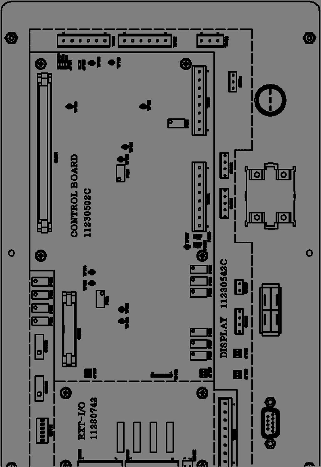
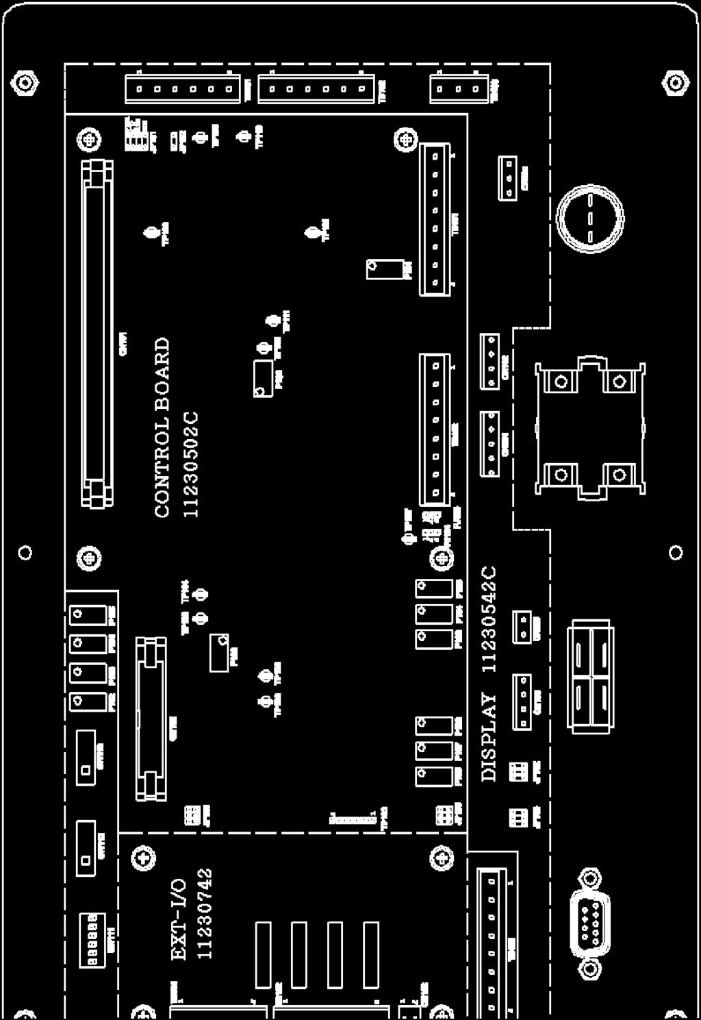
19 7. DISPLAY AND USER INTERFACE There are two main ways of connecting the Power Supply to other devices for control purposes. The first is the 9 pin D-sub connector that is mounted on the front panel. The other way is to connect to terminal blocks within the unit Connecting to the D-Sub connector: This is a RS-485 port with Pin 5 as common, pin 6 as A and pin 7 as B. This connector is in parallel with TB103 on the display board Display Board connectors There are three pluggable terminal connectors inside the power supply on the display board and two on the relay board. They are labeled TB101 TB103, and can be used to make external connections for monitoring the power supply or controlling the power supply functions remotely. TB101 Display Board: Remote Power reference 1) R+10: 10V reference: This 10V reference voltage is available for connecting to a potentiometer remotely. Terminal 1 to top of the pot, terminal 2 to the wiper and terminal 3 (ground) to the bottom of the pot. 2) P-REF: External Power Reference: When SW112, the INT/EXT switch is set to external, the voltage or current level at this terminal controls the command reference. Selecting SW113 for 0-10V, 0 volts is at minimum, and 10 volts is at maximum. Selecting 4-20ma 4ma is at minimum and 20ma is at maximum. A PLC can be connected to terminal 2 with its reference to terminal 3. Proper filtering is important. 3) GRN: Reference Ground: Used with terminals 1&2, the ground for the power reference. 4) M-PWR: Power level monitor in analogue 0-5V 5) M-CVI: Capacitor voltage or inverter current monitor output. Selectable by jumper JP101 on Display Board,pins 1, 2 for capacitor voltage-pins 2, 3 for current reading. 0-5V analogue 6) GRN: Ground for monitor pins. TB102 Display Board: Interlock connectors 1) TEMP: Connection from temperature sensor on input water manifold 2) FLOW: Connection from differential pressure switch assembly 3) DOOR: Connection from door switch 4) GND: Common for pins 1,2,3 & 5. 5) AFBK: Auxiliary feedback: Not active 6) GND: Common TB103 Display Board 1) A 2) B 3) Common 19
20 7.3. Relay Board connectors TB101 Relay Board: Remote contacts These contacts are enabled by soft switches that are set from the front panel. See section 5.4. for further details. 1) HEAT: Connecting terminal 1 to terminal 5 will start the unit. This is enabled when E-H is set to EN1 or EN2. EN1 is for momentary connection and EN2 is for latched operation. 2) E-STOP: Opening a connection between terminal 2 and terminal 5 will stop the heat cycle. This is enabled when E-S is set to EN. This will activate the shunt trip. The front panels E-STOP switch remains in circuit. 3) AUXI: A user defined trip can be wired between terminals 3 and 5. Enabled when E-A is set to EN. 4) RESET: Connecting terminal 4 to terminal 5 will issue a fault reset. This is always enabled. 5) COMMON: Used with above functions only. TB102 Relay Board: Relay contacts These are normally open contacts that have pin 3 as a common. 1) HEAT : Connected to COM when HEAT cycle is on. 2) FAULT: Connected to COM when a FAULT occurs 3) COM: Common connection for the relays 4) READY: Connected to COM when the HEAT cycle is off and no faults exist. 5&6) TRIP These are used by the power supply to sense a trip signal. 20
21 21
22 EXT-TERMINAL BOARD TB1 A - IN 1) +10V: 10V reference: This 10V reference voltage is available for connecting to a potentiometer remotely. Terminal 1 to top of the pot, terminal 2 to the wiper and terminal 3 (ground) to the bottom of the pot. 2) IN: When SW112, the INT/EXT switch is set to external, the voltage or current level at this terminal controls the command reference. Selecting SW113 for 0-10V, 0 volts is at minimum, and 10 volts is at maximum. Selecting 4-20ma, 4ma is at minimum and 20ma is at maximum. A PLC can be connected to terminal 2 with its reference to terminal 3. Proper filtering is important. 3) COM: Reference Ground: Used with terminals 1&2, the ground for the power reference. 4) AFBK: Auxiliary feedback: Not active 5) COM: Reference Ground: TB1 A - OUT 6) PWR: Power level monitor in analogue 0-5V 7) CV / IC: Capacitor voltage or Inverter current monitor output. Selectable by jumper JP101 on Display Board, pins 1& 2 for capacitor voltage, pins 2&3 for current reading. 0-5V analogue 8) COM: Ground for monitor pins. 22
23 TB2 S/W - IN 1) HEAT: Connecting terminal 1 to terminal 5 will start the unit. This is enabled when E-H is set to EN1 or EN2. A foot switch or external ON switch can be connected here. EN1 is a momentary switch while EN2 is a latching function. 2) E-STOP: Opening a connection between terminal 2 and terminal 5 will stop the heat cycle. This is enabled when E-S is set to EN. This will activate the shunt trip. The front panels E-STOP switch remains in circuit. 3) AUX: A user defined trip can be wired between terminals 4 and 5. Enabled when E-A is set to EN. 4) RESET: Connecting terminal 3 to terminal 5 will issue a fault reset. This is always enabled. 5) COMMON 6) COMMON TB3 RELAY Normally open relay connections with 4 being common for all relays. 1) HEAT: Connected to COM, when HEAT cycle is on. 2) FAULT: Connected to COM, when a FAULT occurs 3) READY: Connected to COM, when the HEAT cycle is off and no faults exist. 4) COM: Common connection for relays. 5) COM: Not connected TB4: RS-485 port 1) A 2) B 3) Common TB5: RHS Connects to CN106 on display board 1) S/W: Used to wire switch for RHS 2) COM: common for S/W 3) LED: Used to wire LED for RHS 4) COM: common for LED 23
24 24
Remote Heat Station 40kW; kHz User s Guide
 Remote Heat Station 40kW; 35 400kHz User s Guide RHS-40 Rev. A 1/4/10 Table of Contents 1. SPECIFICATIONS AND FEATURES...3 2. GETTING STARTED...4 3. CONNECTIONS...5 4. LOAD STATION TUNING...6 2 1. Specifications
Induction Power Supply Technical/Service manual for 12.5kW-40kW/480V input 2012
 Induction Power Supply Technical/Service manual for 12.5kW-40kW/480V input 2012 1 INDEX I) SETUP AND USE.. 3 A) Features...3 B) Front panel description...3 C) Set-up...4 D) Tips for Dependable Operation.5-6
Installation and Maintenance Instructions. World Leader in Modular Torque Limiters. PTM-4 Load Monitor
 World Leader in Modular Torque Limiters Installation and Maintenance Instructions PTM-4 Load Monitor 1304 Twin Oaks Street Wichita Falls, Texas 76302 (940) 723-7800 Fax: (940) 723-7888 E-mail: sales@brunelcorp.com
Parker AC10 Frequency Inverter (to 22kW) Easy Start Guide
 Easy Start Guide") Parker AC10 Frequency Inverter (to 22kW) Easy Start Guide CAUTION: 1)Do not re-set while the motor is rotating 2)Perform parts replacement after discharge is finished 3)Do not connect output terminals
Parker AC10 Frequency Inverter (to 22kW) Easy Start Guide CAUTION: 1)Do not re-set while the motor is rotating 2)Perform parts replacement after discharge is finished 3)Do not connect output terminals
OPERATING AND MAINTENANCE MANUAL. Primary Current Injection Test Set. 750ADM-H mk2
 OPERATING AND MAINTENANCE MANUAL Product: Type: Primary Current Injection Test Set 750ADM mk2 750ADM-H mk2 DESIGNED AND MANUFACTURED BY: T & R Test Equipment Limited 15-16 Woodbridge Meadows, Guildford,
POWER SUPPLY MODEL XP-800. TWO AC VARIABLE VOLTAGES; 0-120V and 7A, PLUS UP TO 10A. Instruction Manual. Elenco Electronics, Inc.
 POWER SUPPLY MODEL XP-800 TWO AC VARIABLE VOLTAGES; 0-120V and 0-40V @ 7A, PLUS 0-28VDC @ UP TO 10A Instruction Manual Elenco Electronics, Inc. Copyright 1991 Elenco Electronics, Inc. Revised 2002 REV-I
Troubleshooting Bosch Proportional Valves
 Troubleshooting Bosch Proportional Valves An Informative Webinar Developed by GPM Hydraulic Consulting, Inc. Instructed By Copyright, 2009 GPM Hydraulic Consulting, Inc. TABLE OF CONTENTS Bosch Valves
Section 55 Chapter 6
 Section 55 Chapter 6 REMOTE HYDRAULICS CONTROLLER Calibration and Fault Codes 6-12880NH TABLE OF CONTENTS REMOTE HYDRAULICS CONTROLLER CALIBRATION... 55-5 Requirements For Calibration... 55-5 Aux Set Main
MD10. Engine Controller. Installation and User Manual for the MD10 Engine Controller. Full Version
 MD10 Engine Controller Installation and User Manual for the MD10 Engine Controller. Full Version File: MartinMD10rev1.4.doc May 16, 2002 2 READ MANUAL BEFORE INSTALLING UNIT Receipt of shipment and warranty
SYMBOL LEGEND DANGER WARNING NOTE THIS INDICATES DANGER TO THE LIFE AND HEALTH OF THE USER IS APPROPRIATE PRECAUTIONS ARE NOT TAKEN
 SYMBOL LEGEND DANGER THIS INDICATES DANGER TO THE LIFE AND HEALTH OF THE USER IS APPROPRIATE PRECAUTIONS ARE NOT TAKEN WARNING THIS WARNS THAT MATERIALS MAY BE DAMAGED IF APPROPRIATE PRECAUTIONS ARE NOT
BAPI-Stat 3 Room Sensor
 Overview and Identification The BAPI-Stat 3 is a multiple output transmitter for temperature and humidity with setpoint capability for both and occupied/unoccupied override switching. The large easy-to-read
Self-Testing Industrial Series
 Series: AS-I (Maint.-Free) Self-Testing Industrial Series Emergency Lighting Equipment Instructions for INSTALLATION OPERATION SERVICE SPECIFICATIONS 1300650 1300654 1300666 1300754 1300823 1300886 Hubbell
User s Manual. ACS550-CC Packaged Drive with Bypass Supplement for ACS550-01/U1 Drives User s Manual
 User s Manual ACS550-CC Packaged Drive with Bypass Supplement for ACS550-01/U1 Drives User s Manual ii ACS550-CC Packaged Drive with Bypass ACS550 Drive Manuals GENERAL MANUALS ACS550-01/U1 Drives User's
Axpert-CSS AMTECH DRIVES Axpert-CSS Amtech
 The Axpert-CSS is a range of Combination Soft Starter panels offered by AMTECH DRIVES. We also offer the module unit as an individual product, named as Axpert-Opti torque Soft Starter. This is only the
HGM1780. Automatic Genset Controller USER MANUAL. Smartgen Technology
 HGM1780 Automatic Genset Controller USER MANUAL Smartgen Technology Smartgen Technology Co., Ltd No. 28 Jinsuo Road Zhengzhou Henan Province P. R. China Tel: 0086-371-67988888/67981888 0086-371-67991553/67992951
User s Manual. ACS550-CC Packaged Drive with Bypass Supplement for ACS550-01/U1 Drives User s Manual
 User s Manual ACS550-CC Packaged Drive with Bypass Supplement for ACS550-01/U1 Drives User s Manual ii ACS550-CC Packaged Drive with Bypass ACS550 Drive Manuals GENERAL MANUALS ACS550-01/U1 Drives User's
MANUAL TROUBLESHOOTING. ECM Motor. ECM / ECM-DX Series. v100 Issue Date: 08/15/ Price Industries Limited. All rights reserved.
 MANUAL ECM Motor ECM / ECM-DX Series v100 Issue Date: 08/15/17 2017 Price Industries Limited. All rights reserved. ECM MOTOR TABLE OF CONTENTS ECM Motor Background...1 ECM Motor Power and Control Connectors...2
Optimal Series. Automatic Transfer Switch. Installation and User Manual for the OPT2225 Automatic Transfer Switch. Full Version
 Optimal Series Automatic Transfer Switch Installation and User Manual for the OPT2225 Automatic Transfer Switch Full Version File: OPT2225 Rev2.5.doc November, 2004 2 Thank You For Purchasing This DynaGen
MODEL 520 REMOTE START ENGINE MANAGEMENT SYSTEM
 MODEL 520 REMOTE START ENGINE MANAGEMENT SYSTEM DSE 520 ISSUE 4 4/4/02 MR 1 TABLE OF CONTENTS Section Page INTRODUCTION... 4 CLARIFICATION OF NOTATION USED WITHIN THIS PUBLICATION.... 4 1. OPERATION...
CABINET REEL OPERATING INSTRUCTIONS
 CABINET REEL OPERATING INSTRUCTIONS MODELS 15, 25, 40 & 60 SERIES RAPID-AIR CORPORATION 4601 KISHWAUKEE ST. ROCKFORD, IL 61109-2925 Phone: (815) 397-2578 Fax: (815) 398-3887 Web Site: www.rapidair.com
DC Variable Speed Drive Panel
 DC Variable Speed Drive Panel Installation, Operation & Maintenance Instruction Manual Bulletin #: CC-IOM-0103-D Manufacturers of Quality Pumps, Controls and Systems ENGINEERED PUMP OPERATIONS 2883 Brighton
Spectron Industrial Series
 1300650 1300654 1300666 1300754 1300823 1300886 Table B Constant Value per Voltage System Wire Size (Maximum Voltage Drop 5%) System 6 Volt 12 Volt 24 Volt Wire Size #12 #10 #8 #6 #12 #10 #8 #6 #10 #12
EPS/ELA-Series User Manual EPS/ELA 250W
 EPS/ELA-Series User Manual EPS/ELA 250W EPS Stromversorgung GmbH Tel: +49 (0)821 570451 0 Index 3 Page: 1 Table of contents: Page 1. Features of ELA-Series... 3 1.1 Basic Functions... 3 1.2 Options...
Kelly HSR Series Motor Controller with Regen User s Manual V 3.3. Kelly HSR Opto-Isolated Series Motor Controller with Regen.
 Kelly HSR Opto-Isolated Series Motor Controller with Regen User s Manual HSR72601 HSR72801 HSR12401 HSR12601 HSR12901 HSR14301 HSR14501 HSR14701 Rev.3.3 Dec. 2011 Contents Chapter 1 Introduction... 2 1.1
SECTION 2 - PROCEDURES. Features. 2.6 MOTOR CONTROLLER. Modes of Operation JLG Lift 2-5
 2.6 MOTOR CONTROLLER. Modes of Operation. 1. Traction Motor Drive. a. Drive in either forward or reverse will start only if the following conditions are satisfied: 1. Function switches off. 2. No procedure
Instruction Manual. Q Series 2 Motor Control Modules - OEM
 A382-21-880 Issue B Instruction Manual Q Series 2 Motor Control Modules - OEM Pump/ Q Motor Control Module Item Number pumping system Electrical supply 24 V d.c. control 24 V a.c. control QDP40 200-230
Industrial Controls. Load Feeders and Motor Starters. SIRIUS MCU Motor Starters. Gerätehandbuch. Answers for industry.
 Industrial Controls Load Feeders and Motor Starters SIRIUS MCU Motor Starters Gerätehandbuch Manual Edition 08/2014 Answers for industry. SIRIUS Manual Safety notes 1 Mechanical installation 2 Electrical
PORTABLE CURRENT SOURCE FOR CIRCUIT BREAKER AND MOTOR OVERLOAD TESTING INSTRUCTION MANUAL PI-250B. Release 1.0 April 5, 2013
 PORTABLE CURRENT SOURCE FOR CIRCUIT BREAKER AND MOTOR OVERLOAD TESTING INSTRUCTION MANUAL PI-250B Release 1.0 April 5, 2013 Electrical Test Instruments, Inc. 1301 Avondale Road, Suite J New Windsor, MD
TRAC-3 TENSION READOUT AND CONTROL
 Magnetic Power Systems, Inc. 1626 Manufacturers Drive. Fenton, MO 63026 Tel: 636.343.5550 Fax: 636.326.0608 magpowr@magpowr.com INSTRUCTION MANUAL TRAC-3 READOUT AND CONTROL For Control of Magnetic Particle
Application Engineering
 Application Engineering February, 2009 Copeland Digital Compressor Controller Introduction The Digital Compressor Controller is the electronics interface between the Copeland Scroll Digital Compressor
CURTIS TOLEDO. AF Series Compressors VS models with VFD WARNING
 AUGUST, 2004 REV.A CURTIS TOLEDO OPERATOR S MANUAL SUPPLEMENT AF Series Compressors VS models with VFD WARNING Personal injury and/or equipment damage will result by failing to pay attention to the vital
Phenix Technologies Inc. 75 Speicher Drive Accident, Maryland 21520
 USER S MANUAL PORTABLE HIGH CURRENT TEST SET MODEL NUMBER HC2 Version 4.0 Phenix Technologies Inc. 75 Speicher Drive Accident, Maryland 21520 Copyright Phenix Technologies, Inc. Rev 11/20/2014 nab TABLE
SE-3SCR-LM MANUAL MOTOR LOAD MANAGER
 3714 Kinnear Place Saskatoon, SK Canada S7P 0A6 Ph: (306) 373-5505 Fx: (306) 374-2245 www.littelfuse.com/relayscontrols SE-3SCR-LM MANUAL MOTOR LOAD MANAGER MARCH 5, 2013 REVISION 4 MOTOR LOAD MANAGER
Application Note. First trip test. A circuit breaker spends most of its lifetime conducting current without any
 Application Note First trip test A circuit breaker spends most of its lifetime conducting current without any operation. Once the protective relay detects a problem, the breaker that was idle for maybe
SmartPak Welding Controller WK-MPS-16 Constant Current
 SmartPak Welding Controller WK-MPS-16 Constant Current Features Latest state of the art ATMEL 8 bit microprocessor technology Synchronous digital welding control allows absolute precision Up to16 programmers
Electronic Ballast EVG 2000-T
 Electronic Ballast EVG 2000-T Operating Manual Table of contents 1 Description 1.1 Advantages of this ballast... 3 1.2 Functional principle... 3 1.3 Energization... 4 1.4 Visualization... 5 1.5 Indications
NEMA 1, NEMA 4X and Chassis Mount Adjustable Speed Controls for DC Motors
 Made in the U.S.A. NEMA 1, NEMA 4X and Chassis Mount Adjustable Speed Controls for DC Motors Nema Enclosed DC Control Specifications Catalog Number BC140 or Features BC138 BC139 BC140-FBR BC154 BC160 BCWD140
Dycon D2430 EN54-4 Fire Alarm Power Supply Series
 Dycon D2430 EN54-4 Fire Alarm Power Supply Series Technical Description Installation and Operating Manual Construction Product Regulation 0359-CPR-00434 Page 1 of 14 Contents 1. General... 3 1.1 Product
RE-PR3-E-86&105 3-Phase Panel Mount 86 and 105kW
 Page 1 of 6 3-Phase Panel Mount 86 and 105kW Features: Benefits: 0-10Vdc, 0-5Vdc, 4-20mA or manual via potentiometer control input Over temperature protection with auto reset Enclosed panel mounting Efficient
Data Bulletin. Ground-Censor Ground-Fault Protection System Type GC Class 931
 Data Bulletin 0931DB0101 July 2001 Cedar Rapids, IA, USA Ground-Censor Ground-Fault Protection System Type GC Class 931 09313063 GT Sensor Shunt Trip of Circuit Interrupter Window Area for Conductors GC
GE Sensing & Inspection Technologies
 GE Sensing & Inspection Technologies Modus Model RPM-1 Room Pressure Monitor Installation and Setup Guide 1. GENERAL The RPM-1 monitors either positive or negative room pressures (see the Datasheet for
Valcom Failsafe Unit. 1620ESv2 SERIES. Operation and Maintenance Manual
 Valcom Failsafe Unit 1620ESv2 SERIES Operation and Maintenance Manual Table of Contents Section Title Page 1. - Introduction.. 2. - Unpacking the Failsafe unit. 3. - Installation 3.1 - Auto / Timed UPS
Te 803 Electronic Controller. Service, Operation & Technical Information Manual
 Te 803 Electronic Controller Service, Operation & Technical Information Manual WARNING! Technical descriptions and data given in this document are accurate, to the best of our knowledge, but can be subject
User s Manual. ACH550-CC/CD Packaged Drive with Classic Bypass Supplement for ACH550-UH HVAC User s Manual
 User s Manual ACH550-CC/CD Packaged Drive with Classic Bypass Supplement for ACH550-UH HVAC User s Manual ii ACH550-CC/CD Packaged Drive with Classic Bypass ACH550 Drive Manuals GENERAL MANUALS ACH550-UH
Series 70 24V On/Off Electric Actuator Operation and Maintenance Manual
 Series 70 Operation and Maintenance Manual TABLE OF CONTENTS 1. Definition of Terms............................................. 1 2. Safety................................................... 1 3. Storage..................................................
HT Dielectric Withstand Tester Volts AC Output 25mA Leakage Option
 HT-10000 Dielectric Withstand Tester 0-10000 Volts AC Output 25mA Leakage Option Instruction Manual COMPLIANCE WESTUSA Dear Customer: Congratulations! Compliance West USA is proud to present you with your
NV Direct Coupled Globe Valve Actuator
 70396 Rev. C Non-spring return, on/off, floating point, proportional control NV Direct Coupled Globe Valve Actuator NV24-3 US NVD24-3 US NV24-MFT US NVD24-MFT US Application For on/off, floating point
XENON POWER SUPPLY 4000 Watt Gladiator IV
 XENON POWER SUPPLY 4000 Watt Gladiator IV 220 Volt Equipment Type 62-00049 Rev. February 2003 STRONG INTERNATIONAL a division of Ballantyne of Omaha, Inc. 4350 McKinley Street Omaha, Nebraska 68112 USA
CV - 6SL INSTRUCTION MANUAL 6000W POWER SUPPLY
 CV - 6SL INSTRUCTION MANUAL 6000W POWER SUPPLY 1 TABLE OF CONTENTS 1.0 Specification 5 2.0 Installation 7 2.1 Rack Mounted 7 2.2 Cooling 7 2.3 Filament Module 8 2.4 Electrical Power Input 8 2.5 Grounds
SOLAR LIGHTING CONTROLLER SUNLIGHT MODELS INCLUDED IN THIS MANUAL SL-10 SL-10-24V SL-20 SL-20-24V
 SOLAR LIGHTING CONTROLLER OPERATOR S MANUAL SUNLIGHT MODELS INCLUDED IN THIS MANUAL SL-10 SL-10-24V SL-20 SL-20-24V 10A / 12V 10A / 24V 20A / 12V 20A / 24V 1098 Washington Crossing Road Washington Crossing,
DKG-114 MANUAL AND REMOTE START UNIT
 DKG-114 MANUAL AND REMOTE START UNIT FEATURES Both manual and remote controlled engine starting and stopping, Automatic shutdown on fault condition, Optional cooldown cycle on remote start operation, Optional
Combined Ventilation Controller RVWS-T-224HA
 Combined Ventilation Controller RVWS-T-224HA 8-stage Control for Power/Natural Applications 2 variable speed stages, 2 curtain winch stages, 2 fixed speed ventilation stages, 1 thermo/mister cycle stage
Modulating Furnace Information. Warning on Meter Setting - Read First!
 Modulating Furnace Information Pressure Transducer Pressure DC Volts 0.00" 0.25 0.20" 0.63 0.25" 0.72 0.30" 0.82 0.35" 0.91 0.40" 1.00 0.45" 1.09 0.50" 1.19 0.55" 1.28 0.60" 1.38 0.65" 1.47 0.70" 1.56
POWERLINE 2000 Energy Management System TM
 Display Panel TM The PowerLine 00 EMS is a specialized power distribution and energy management system intended to be used in recreational vehicles. The Control Module is housed in the standard main distribution
User s Manual. ACH550-CC/CD Packaged Drive with Classic Bypass Supplement for ACH550-UH HVAC User s Manual
 User s Manual ACH550-CC/CD Packaged Drive with Classic Bypass Supplement for ACH550-UH HVAC User s Manual ii ACH550-CC/CD Packaged Drive with Classic Bypass ACH550 Drive Manuals GENERAL MANUALS ACH550-UH
GLM SERIES CONTROL Users Manual Rev:
 GLM SERIES CONTROL Users Manual Rev: 808062 Connecting Power Page 2 Motor Terminal Wiring Diagrams Page 3 Getting Started / Setup Page 4 1. Obstruction Detection Devices Page 4 2. Checking Power and Direction
Programmable Logic Controller. Mat Nor Mohamad
 Programmable Logic Controller Mat Nor Mohamad Relays Electromagnetic Control Relays The PLC's original purpose was the replacement of electromagnetic relays with a solid-state switching system that could
SYMBOL LEGEND DANGER WARNING NOTE THIS INDICATES DANGER TO THE LIFE AND HEALTH OF THE USER IS APPROPRIATE PRECAUTIONS ARE NOT TAKEN
 SYMBOL LEGEND DANGER THIS INDICATES DANGER TO THE LIFE AND HEALTH OF THE USER IS APPROPRIATE PRECAUTIONS ARE NOT TAKEN WARNING THIS WARNS THAT MATERIALS MAY BE DAMAGED IF APPROPRIATE PRECAUTIONS ARE NOT
TECHNICAL PAPER 1002 FT. WORTH, TEXAS REPORT X ORDER
 I. REFERENCE: 1 30 [1] Snow Engineering Co. Drawing 80504 Sheet 21, Hydraulic Schematic [2] Snow Engineering Co. Drawing 60445, Sheet 21 Control Logic Flow Chart [3] Snow Engineering Co. Drawing 80577,
SALDET SALES & SERVICE, INC. CLINTON TOWNSHIP, MICHIGAN
 Form 1254 BRAKETRON Electronic Motor Brake Instructions SALDET SALES & SERVICE, INC. CLINTON TOWNSHIP, MICHIGAN TABLE OF CONTENTS SECTION TITLE PAGE I. Introduction 1 II. Specifications 1 III. Principles
Kelly HPM High Power Full Bridge Permanent Magnet DC Motor Controller User s Manual
 Kelly HPM High Power Full Bridge Permanent Magnet DC Motor Controller User s Manual HPM72601 HPM72801 HPM12401 HPM12601 HPM12801 HPM14301 HPM14501 HPM14701 Rev.3.4 Dec. 2016 Contents Chapter1 Introduction...
SYSDrive Frequency Inverter
 SYSDrive Frequency Inverter T V/f control T PID control T Standard LED, optional LCD operator T Fieldbus options: DeviceNet T 7 configurable digital inputs T 3 configurable digital outputs T Low audible
Application Engineering
 Application Engineering March 2011 Copeland Digital Compressor Controller Introduction The Digital Compressor Controller is the electronics interface between the Copeland Scroll Digital compressor or the
TRIPS AND FAULT FINDING
 WWW.SDS.LTD.UK 0117 9381800 Trips and Fault Finding Chapter 6 6-1 TRIPS AND FAULT FINDING Trips What Happens when a Trip Occurs When a trip occurs, the drive s power stage is immediately disabled causing
Installation Instructions & Users Manual
 Installation Instructions & Users Manual UTILITY/ BUILDING INPUT 120 VAC ( OPTION) 15-20A N L CONTROL BOARD G SECURITY LIGHTING POWER SUPPLY (OPTION) CHARGER- POWER SUPPLY ASSBY XFMR (OPTION) CBM MODEL
ASSA ABLOY Series Power Operator Installation and Instruction ASSA Manual ABLOY ASSA ABLOY
 00 Series Power Operator Installation and Instruction ASSA Manual ABLOY Item No. Description Motor (00M) Cover (00COV) Control Inverter (00IN) Power Supply VDC (00PS) Track Assembly (0-) / Replacement
Table 1: 2-pin Terminal Block J1 Functional description of BSD-02LH Module Pin # Pin Description Table 2: 10-pin Header J2 Pin # Pin Description
 Functional description of BSD-02LH Module The BSD-02LH module is the part of the BSD-02 family of drivers. The main difference is higher microstepping resolution. The BSD-02LH is suitable for driving bipolar
Model Number Structure. Power Controllers G3PX. Single-phase Models. Model Number Legend
 Power Controllers GPX Refer to Safety Precautions (page 0). Single-phase Models EUN Series AC Power Controllers with Phase-control System Allow Precise Temperature Control Models with Base-up and Soft-start
KV4-300 mk2. KV5-200 mk2. KV5-100T mk2. KV3-250 mk2
 OPERATING AND MAINTENANCE MANUAL Product: Type: High Voltage AC Test Set KV3-250 mk2 KV4-300 mk2 KV5-100 mk2 KV5-100T mk2 KV5-200 mk2 DESIGNED AND MANUFACTURED BY: T & R Test Equipment Limited 15-16 Woodbridge
Kit. Hydraulic Kit Installation Guide REV A. Item Component Part Number Qty
 Hydraulic Kit Installation Guide Item Component Part Number Qty 1. HOSE ASSY. 3/8" X 110" -8F ORFS X -8F ORFS 90 DEG F451TC-JCJ9080806-110 1 2. HOSE ASSY. 3/8" X 110" -6F ORFS X -8F ORFS 90 DEG F451TC-JCJ9060806-110
AxCent Servo Drive AB30A200
 Description Power Range The AB30A200 PWM servo drive is designed to drive brushless and brushed type DC motors at a high switching frequency. A single red/green LED indicates operating status. The drive
HIB Enclosed Inverter User Guide
 HIB Enclosed Inverter User Guide (0.75kW~22kW) V1.2.0 Contents 1 Safety information...1 2 Technical Data...2 3 Motor Connection...4 4 Operation...5 5 Single phase circuit diagram...7 6 Three phase circuit
INSTALLATION INSTRUCTIONS AND OPERATION MANUAL
 INSTALLATION INSTRUCTIONS AND OPERATION MANUAL UL325-2010 Compliant Commercial and Industrial Door Operator Logic Control Continuous Duty IMPORTANT INSTALLATION INSTRUCTIONS WARNING To reduce the risk
Horizontal Circuit Switchers
 > Transformer Protection > CIRCUIT SWITCHERS C A T A L O G B U L L E T I N General Application Southern States Types CSH and CSH-B Horizontal Circuit Switchers provide an economical, versatile, space saving
CENTRIFEEDER ELECTRONICS
 CENTRIFEEDER ELECTRONICS FOR USE WITH CENTRIFEEDER with Integrated Vibratory Control REV 08/13 ADDENDUM VERSION 6.22 SOFTWARE Copyright 2011 Eastern Instrument Laboratories, Inc. All Rights Reserved. TABLE
Horizontal Circuit Switchers
 > Transformer Protection > CIRCUIT SWITCHERS C A T A L O G B U L L E T I N General Application Southern States Types CSH and CSH-B Horizontal Circuit Switchers provide an economical, versatile, space saving
XENON POWER SUPPLY Compact Model 220 Volt Equipment Type
 XENON POWER SUPPLY Compact Model 220 Volt Equipment Type 62-80106 62-80108 62-80109 62-80113 Rev. August 2001 STRONG INTERNATIONAL a division of Ballantyne of Omaha, Inc. 4350 McKinley Street Omaha, Nebraska
Automotive Application ET01 Software Revision A 12/06
 Automotive Application ET01 Software Revision A 12/06 INTRODUCTION... 2 FUNCTIONAL DESCRIPTION... 3 INSTALLATION... 4 COMPONENT PLACEMENT... 4 PLUMBING AND WIRING... 5 MSBC OPERATION (ET-01)... 14 TIMED
J1 Plug Pin Identification
 D5 D8 D7 D4 D5 D ART_8 J 4 8 D D0 7 R R R R4 TB 80 D D D D4 D D J Plug Pin Identification PIN # WIRE # SIGNAL FUNCTION 0 INPUT Drive Reverse INPUT Drive Forward OUTPUT Brake, Decel Valve signal 4 8 INPUT
AUTO REEL -AS MODEL #: AS AUTOMATIC CORD REEL WITH AUTO SAFE INSTRUCTION MANUAL
 INSTRUCTION MANUAL AUTO REEL -AS AUTOMATIC CORD REEL WITH AUTO SAFE MODEL #: 091-220-20-120-AS INPUT: 120 Volts, 50/60 Hz, 20 Amps File: IM_091-220-20-120-AS_revA.indd Rev: A Revised By: JM Date: 06-09-2015
World Class Power Solutions. Rectifiers. For Stationary Battery Systems in Nuclear Power Plants
 World Class Power Solutions Rectifiers For Stationary Battery Systems in Nuclear Power Plants General 2 1.1 Application Electronically controlled rectifier assemblies are used in conjunction with suitable
Your Global Flow Control Partner. Series 70 24V On/Off Electric Actuator Operation and Maintenance Manual
 Your Global Flow Control Partner Series 70 Table of Contents 1. Definition of Terms.......................................2 2. Safety............................................. 2 3. Storage............................................2
Generator Sets Controller 210. Operation Manual. Ver1.0
 Generator Sets Controller 210 Operation Manual Ver1.0 Note This information could include technical inaccuracies or typographical error. Manufacturer may make improvements and/or changes in the product(s)
Kelly KDHA High Voltage Series/PM Motor Controller User s Manual
 Kelly KDHA High Voltage Series/PM Motor Controller User s Manual KDH07500A KDH07501A KDH07700A KDH07701A KDH09400A KDH09401A KDH09500A KDH09501A KDH12400A KDH12401A KDH12500A KDH12501A KDH14300A KDH14301A
Welcome to ABB machinery drives training. This training module will introduce you to the ACS850-04, the ABB machinery drive module.
 Welcome to ABB machinery drives training. This training module will introduce you to the ACS850-04, the ABB machinery drive module. 1 Upon the completion of this module, you will be able to describe the
Automatic Genset Controller, AGC-4 Display readings Push-button functions Alarm handling Log list
 OPERATOR'S MANUAL Automatic Genset Controller, AGC-4 Display readings Push-button functions handling Log list DEIF A/S Frisenborgvej 33 DK-7800 Skive Tel.: +45 9614 9614 Fax: +45 9614 9615 info@deif.com
FLÄKTGROUP PM-MOTOR WITH INTEGRATED FC 106 FREQUENCY CONVERTER
 FLÄKTGROUP PM-MOTOR WITH INTEGRATED FC 106 FREQUENCY CONVERTER INSTALLATION AND MAINTENANCE INSTRUCTIONS Risk of electric shock: Motor terminals may still be live if the impeller is rotating, even when
Power Controller. (see note 1) 10 sec
 10 sec") Power Controller Single-phase Models EUN Series AC Power Controller with Phase-control System Allows Precise Temperature Control Models with Base-up and Soft-start Functions Available EH Series Phase Control
Power Controller Single-phase Models EUN Series AC Power Controller with Phase-control System Allows Precise Temperature Control Models with Base-up and Soft-start Functions Available EH Series Phase Control
Fincor Series 2230 MKII/2240
 Fincor Series 2230 MKII/ Fincor Series 2200 regenerative drives are ideal for your more demanding applications. They feature flexibility with ratings up to 5 horsepower. The Series 2230 MKII offers new
1.0 Features and Description
 1.0 Features and Description The is an intelligent actuator designed for precise control of quarter turn valves and dampers. Using stepper motor technology, the SmartStep proportionally positions valves
Intelligent torque meter tester
 Intelligent torque meter tester Before using this product, please read the instructions carefully, which will help improve the efficiency of your use of this product Contents 一 About HP Series Torque Meter...2
Brushed. Brushed. Brushed Motor
 Kelly Kelly Kelly Kelly KD KD KD KD Series Series Series Series DC DC DC DC Motor Motor Motor Motor Controller Controller Controller Controller User User User User s Manual Manual Manual Manual V 2.5 2.5
INSTRUCTION MANUAL FOR Revision C MODEL SERIAL NUMBER LAMBDA EMI 405 ESSEX ROAD, NEPTUNE, NJ 07753
 INSTRUCTION MANUAL FOR 8-494-001 Revision C MODEL SERIAL NUMBER LAMBDA EMI 405 ESSEX ROAD, NEPTUNE, NJ 0775 TEL: (72) 922-900 FAX: (72) 922-94 Table of Contents Description 1 GENERAL 1.1 INTRODUCTION 2
NEW ZEALAND POST OFFICE NEGATIVE 50V D.C. TO POSITIVE 50V D.C. SUPPLY NOTES PR 2157 ISSUE 1 APRIL 1977
 NEW ZEALAND POST OFFICE NEGATIVE 50V D.C. TO POSITIVE 50V D.C. SUPPLY NOTES PR 2157 ISSUE 1 APRIL 1977 1. GENERAL. 1.1 These PR notes supersede notes PR 2133 and should only be used in conjunction with
Dielectric Withstand Tester
 Dielectric Withstand Tester Model HT-20KVPac 0-20,000 Volts AC Output Instruction Manual i Dear Customer: Congratulations! Compliance West USA is proud to present you with your Dielectric Withstand Tester.
PT Series Phase Converters OPERATION & INSTALLATION MANUAL
 PT Series Phase Converters OPERATION & INSTALLATION MANUAL SAFETY MESSAGES AND WARNINGS To ensure safe and reliable operation of the PT Series phase converter, it is important to carefully read this manual,
MM1/MM2 INSTALLATION & MAINTENANCE INSTRUCTIONS
 MM1/MM2 INSTALLATION & MAINTENANCE INSTRUCTIONS DESCRIPTION / IDENTIFICATION The MM series proportional control valves utilize ProportionAir's unique closed loop control technology for superior control
Full Bridge Permanent Magnet DC Motor Controller User's Manual
 www.igreatway.com Email:info@igreatway.com V 3.3 Full Bridge Permanent Magnet DC Motor Controller User's Manual PM24101 PM24201 PM24301 PM36101 PM36201 PM48101 PM48201 PM48301 PM48401B PM48501B PM72101
RAPID-AIR OPERATING INSTRUCTIONS FOR RD317S, RD417M RIM DRIVE
 RAPID-AIR OPERATING INSTRUCTIONS FOR RD37S, RD47M RIM DRIVE RAPID-AIR 460 KISHWAUKEE ST. ROCKFORD, IL. 609-95 PHONE: (85) 397-578 FAX: (85) 398-3887 WEB SITE: www.rapidair.com TABLE OF CONTENTS PAGE. RIM
Observe all necessary safety precautions when controlling the soft starter remotely. Alert personnel that machinery may start without warning.
 Introduction OPERATING INSTRUCTIONS: MCD REMOTE OPERATOR Order Codes: 175G94 (for MCD 2) 175G361 + 175G9 (for MCD 5) 175G361 (for MCD 3) 1. Introduction 1.1. Important User Information Observe all necessary