1. AC VOLTS: Displays generator output in voltage. 2. AC FREQUENCY: Displays the speed of the generator set in Hertz.
|
|
|
- Bertha Adams
- 6 years ago
- Views:
Transcription


1 1. AC VOLTS: Displays generator output in voltage. 2. AC FREQUENCY: Displays the speed of the generator set in Hertz. 3. AMMETER/PERCENT OF LOAD: Displays the load on the generator in amps or in percentage. 4. Control Toggle Switch: Switches generator from off to manual position or auto position. 5. Running Time Meter: Displays the number of hours the generator set has run. 6. Engine Control Indicator Lights: Indicates specific shutdowns of the generator set. 7. Oil Pressure Gauge: Displays oil pressure of engine while running. 8. Water Temperature Gauge: Displays the coolant temperature of the coolant inside the engine. 9. DC Voltmeter: Displays the battery voltage. 10. Fuel Gauge: Displays the fuel level in the tank.
2 AUTOMATIC ENGINE CONTROL DIESEL/GAS ENGINES The ECU -CAN engine control provides complete automation and safety monitoring of a gas or diesel engine. The ECU -CAN controls the starter and fuel thus completely taking the operator out of the picture. A built in speed switch controls both starter disengagement and overspeed protection. Speed and shutdown information are derived from the CAN BUS SPEED. ECU -CAN ONE VERSION FOR 12 AND 24 VDC APPLICATIONS: Generator Control Panels, Automatic Engine Systems FEATURES: Loss of Speed Data or CAN Signal detection during both cranking and running Overspeed verify without engine damage Built in speed switch using CAN data HWT and LOP faults via CAN bus Low oil pressure and high water temp override during cranking Wide temperature range -40C to +85C Epoxy encapsulated module for excellent field reliability LEDS with auto/manual lamp test All preset at factory no field adjustments ECU -CAN A COMPLETE AUTOMATIC ENGINE CONTROL The ECU-CAN covers just about all the essential engine control functions that are asked for in most specifications. Glow plug delay is achieved via an internal lookup table in conjunction with Fuel temperature. The ECU-CAN automatically cranks, starts and monitors an engine for Overcrank, Overspeed, High Water Temperature and Low Oil Pressure. All adjustments are factory set. A built in speed switch uses a CAN speed signal to monitor engine speed for crank disconnect and overspeed. The bypass timer/logic assures Low Oil Pressure and High Water Temp override during the crank period and an additional adjustable period after crank disconnect. The ECU-CAN expands to as many faults as required by using the Engine Alarm Input/ Output. The ECU-CAN monitors the CAN signal for problems during both cranking and running. If a problem is detected the engine will shutdown and the Overcrank and Overspeed LED's will both turn on. Specifications Subject to Change Without Notice ECU -CAN F
3 SAMPLE ECU -CAN APPLICATION: AUTOMATIC ENGINE CONTROL OF DIESEL/GAS ENGINE FUEL RELAY FR REMOTE START CONTACTS AUTO OFF 10 AMP FUSE BATTERY START RELAY SR X1 MANUAL ENGINE ECM BATTERY POSITIVE CAN LO CAN HI LAMP TEST Shielded OVERSPEED VERIFY ENGINE STARTED LAMP COMMON ALARM LAMP For Overspeed verify short pins together EXTRA FAULTS TIE TO BATTERY POSITIVE The above illustrates the ECU-CAN engine control with an energized to run engine. Placing the control switch in MANUAL or closure of the Remote Start Contacts while in AUTO initiates the Crank mode. The Fuel and Starter Relays are energized causing the engine to begin cranking. If the engine does not start in the allotted time the Overcrank Fault occurs, and the Fuel and Starter Relays are turned off. If during cranking the internal speed switch detects a speed equal to or above the Crank Disconnect Pre-Set the Starter Relay turns off, the LOP/HWT delay timer is initiated. After this delay period if the LOP or HWT switch closes the engine will shutdown immediately. If the internal speed switch detects a speed equal to or above the Overspeed Setting the engine is shutdown immediately. To stop the engine or to clear a fault condition place the control switch in the Off position. Based on an internal wait table and the fuel temperature from the CAN data the unit delays for the glow plug time period before start. If the CAN or Speed signal from the Engine ECM is lost during cranking or running the engine will shut down and the Overcrank & Overspeed LED's will both turn on. SPECIFICATIONS: VOLTAGE RANGE - 9 TO 28 VOLTS STARTER AND FUEL OUTPUT - 5 AMPS MAX LAMP OUTPUTS (TOTAL) - 1 AMP MAX ECU -CAN TERMINAL OUT AUTO FUEL RELAY OUTPUT MANUAL PHYSICAL DIMENSIONS X1 STARTER RELAY OUTPUT CAN LOW CAN HIGH LAMP TEST BATTERY NEGATIVE OVERSPEED VERIFY For Overspeed Verify short pins together ENGINE STARTED LAMP OUTPUT ALARM OUT EXTRA FAULT IN.300 INCH MM BACK VIEW SIDE VIEW
4 AUTOMATIC ENGINE CONTROL FOR DIESEL/GAS ENGINES The ECU-9988N engine control provides complete automation and safety monitoring of a gas or diesel engine. The ECU-9988N controls the starter and fuel thus completely taking the operator out of the picture. A built in speed switch controls both starter disengagement and overspeed protection. ECU -9988N ONE VERSION FOR 12 AND 24 VDC APPLICATIONS: Generator Control Panels, Automatic Engine Systems FEATURES: Loss of Magnetic Pickup detection during both cranking and running Single or Multi-crank modes are field adjustable Built in speed switch Grounded or positive HWT/LOP inputs Low oil pressure and high water temp override during cranking Wide temperature range -40C to +85C Epoxy encapsulated module for excellent field reliability LEDS with auto/manual lamp test 1 AMP Relays for annunciator outputs ECU -9988N A COMPLETE AUTOMATIC ENGINE CONTROL The ECU-9988N covers just about all the essential engine control functions that are asked for in most specifications. The ECU-9988N automatically cranks, starts and monitors an engine for Overcrank, Overspeed, High Water Temperature and Low Oil Pressure. Any crank timing sequence is accomplished by using the multiple or single crank modes in conjunction with the timer adjustments. A built in speed switch uses a magnetic pickup to monitor engine speed for crank disconnect and overspeed. The bypass timer/logic assures Low Oil Pressure and High Water Temp override during the crank period and an additional adjustable period after crank disconnect. The ECU-9988N expands to as many faults as required by using the Engine Alarm Input/Output. The ECU-9988N monitors the Magnetic Pickup signal for problems during both cranking and running.if a problem is detected the engine will shutdown and the Overcrank and Overspeed LED's will both turn on. Specifications Subject to Change Without Notice ECU -88N 0803F
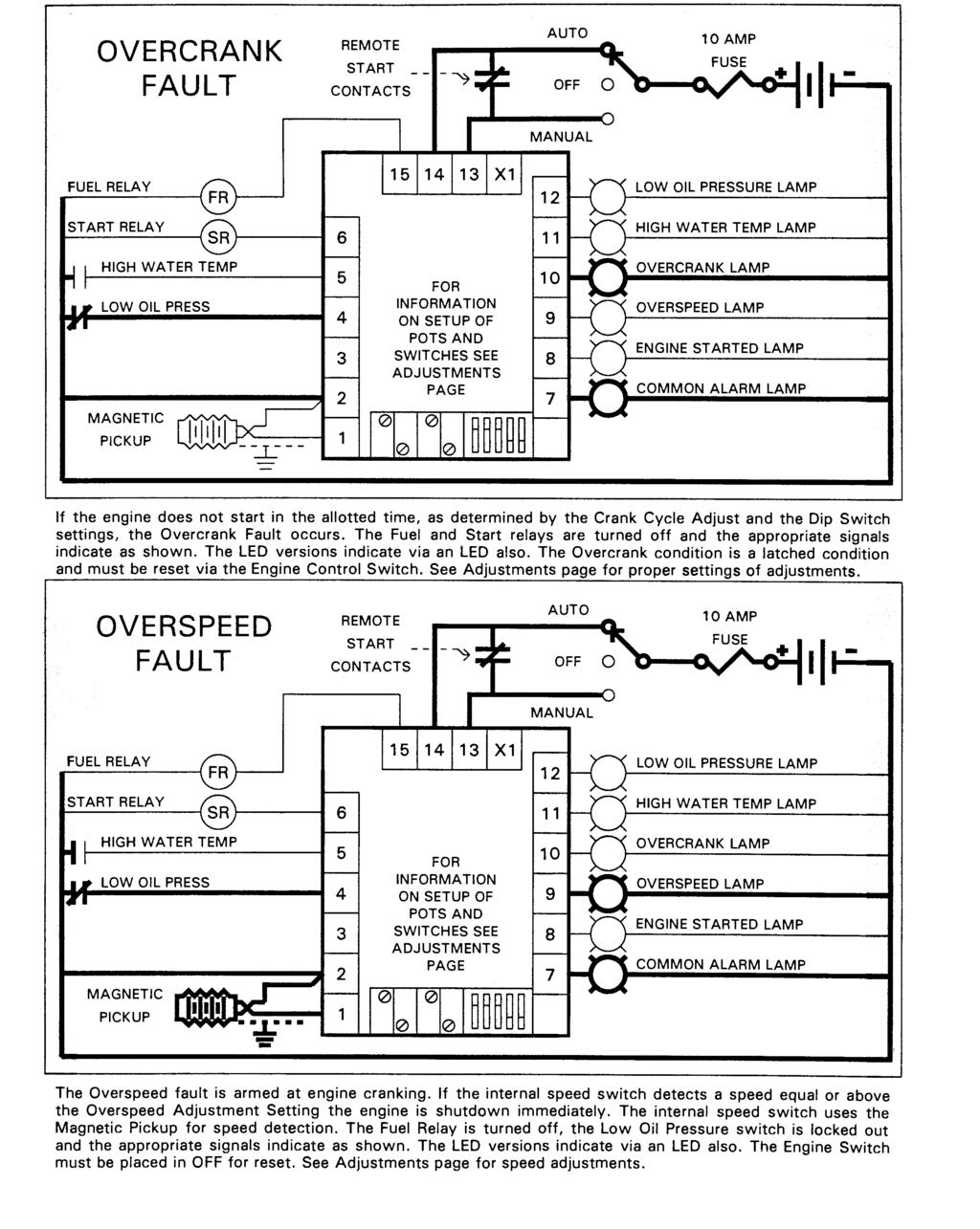
5 SAMPLE ECU -9988N APPLICATION: FUEL RELAY FR REMOTE START CONTACTS AUTO OFF 10 AMP FUSE BATTERY START RELAY BATTERY POSITIVE HIGH WATER TEMP LOW OIL PRESS MAGNETIC PICKUP INPUT SR LAMP TEST X1 HIGH WATER TEMP OIL PRESS DELAY CRANK ATTEMPTS OVER SPEED CRANK DISCONNECT CRANK CYCLE MANUAL LOW OIL PRESSURE LAMP HIGH WATER TEMP LAMP OVERCRANK LAMP OVERSPEED LAMP ENGINE STARTED LAMP COMMON ALARM LAMP EXTRA FAULTS TIE TO BATTERY POSITIVE OVERSPEED VERIFY SINGLE OR CYCLE CRANK The above illustrates the ECU-9988N engine control with an energized to run engine. Placing the control switch in MANUAL or closure of the Remote Start Contacts while in AUTO initiates the Crank mode. The Fuel and Starter Relays are energized causing the engine to begin cranking. If the engine does not start in the allotted time, as determined by the Crank Cycle Adjust and Dip Switch setting, the Overcrank Fault occurs, and the Fuel and Starter Relays are turned off. If during cranking the internal speed switch detects a speed equal to or above the Crank Disconnect Adjustment Setting the Starter Relay turns off, the LOP/HWT delay timer is initiated. After this delay period if the LOP or HWT switch closes the engine will shutdown immediately. If the internal speed switch detects a speed equal to or above the Overspeed Adjustment Setting the engine is shutdown immediately. To stop the engine or to clear a fault condition place the control switch in the Off position. If the signal from the magnetic pickup is lost during cranking or running the engine will shut down and the Overcrank & Overspeed LED's will both turn on. SPECIFICATIONS: VOLTAGE RANGE - 9 TO 28 VOLTS MAGNETIC PICKUP HERTZ STARTER AND FUEL OUTPUT - 5 AMPS MAX LAMP OUTPUTS (TOTAL) - 1 AMP MAX ECU -9988N TERMINAL OUT PHYSICAL DIMENSIONS AUTO FUEL RELAY OUTPUT MANUAL X1 12 LOW OIL PRESSUR LAMP OUTPUT STARTER RELAY OUTPUT HIGH WATER TEMP. INPUT LOW OIL PRESSURE INPUT LAMP TEST BATTERY NEGATIVE MAGNETIC PICKUP INPUT OIL PRESS DELAY OVER SPEED CRANK DISCON CRANK CYCLE HIGH WATER TEM LAMP OUTPUT OVERCRANK LAMP OUTPUT OVERSPEED LAMP OUTPUT ENGINE STARTED LAMP OUTPUT ALARM OUT EXTRA FAULT IN OVERSPEED VERIFY INCH MM BACK VIEW SIDE VIEW CRANK ATTEMPTS SINGLE OR CYCLE CRANK Mounting holes will accept No. 8 or No. 6 screws. All dimensions in inches.
6 Adjusting an ECU engine control with pots Adjusting Crank Disconnect This adjusts when the starter disengages upon start Turn the Crank Disconnect adjustment 30 turns counter clockwise. Then turn it about 3 turns clock wise. Try to start the engine. It should crank and stop quickly. If your engine control has an engine started LED it will be lit. Now try turning the crank disconnect adjustment 1 turn clockwise and try restarting the engine. Keep turning the adjustment clockwise and attempting to start until the engine starts reliably. If the Overcrank and Overspeed LEDS light at the same time on your unit see the trouble shooting guide for more help. Adjusting Overspeed This adjusts overspeed safety trip Be sure you have adjusted the crank disconnect first. Turn the Overspeed adjustment 30 turns clockwise. Flip Switch 5 to the on position. Start the engine. It should crank and start. If your engine control has an engine started LED it will be lit. Now start turning the overspeed adjustment counterclockwise until the engine control shuts down the engine in an overspeed fault. Turn Sw 5 off. If the Overcrank and Overspeed LEDS light at the same time on your unit see the trouble shooting guide for more help. Adjusting Fault Delay This adjusts how long engine can run in fault mode Turn the Fault Delay adjustment 30 turns counter clockwise. This will allow for about 1 second of fault delay. Fault delay is begun after the engine has started. The purpose of the delay is to allow time for oil pressure to build adequately before the oil pressure monitor starts checking the oil pressure sender. High water temperature is also ignored during the fault delay time to allow engine coolant to circulate in the engine. Adjusting Crank Time This adjusts starter on time Turn the Crank Disconnect adjustment 30 turns counter clockwise. Then turn it about 3 turns clock wise. This will allow about 1 second or so of actual engine cranking (starting motor on) time. Each turn up adds about 1 second to the crank time. Adjusting the crank time automatically sets the rest time to the same value.

7 Adjusting an ECU engine control with DIP switch SW1 SW2 SW3 CYCLES OFF OFF OFF 1 OFF ON OFF 2 ON OFF OFF 3 ON ON OFF 4 OFF OFF ON 5 OFF ON ON 6 ON OFF ON 7 ON ON ON 8 Adjusting Crank Cycles Using a pen or small screwdriver and the table on the side of the engine control flip the switches in the pattern to adjust to your desired amount of cycles. Cycles is the amount of times the engine will turn on the starter to attempt engine cranking. Adjusting Single or Multiple cranks Using a pen or small screwdriver adjust switch 4 on for one single crank. This action causes all the multi cranks to add together to create one large crank. In affect it disables the rest cycles. SW 4 ON OFF Action Single Crank Multiple Cranks Using the overspeed verify switch After engine starts and engine is at speed turn this switch on and if properly set the engine will shutdown in overspeed fault. Be sure switch 5 is turned off for proper normal operation. SW 5 ON OFF Action Makes control think engine is going approximately 13% faster than it really is True engine speed
8
9
10
11
12
13
14
15
16
ANALOG CONTROL PANEL
 ANALOG CONTROL PANEL 1. AC VOLTS: Displays generator output in voltage. 2. AC FREQUENCY: Displays the speed of the generator set in Hertz. 3. Percent of Load: Displays percentage of load on the generator.
ECU. Speed Switch Manual. Contents. ECU is a registered trademark of Engineering Concepts Unlimited Inc.
 ECU Speed Switch Manual Contents ECU is a registered trademark of Engineering Concepts Unlimited Inc. Contents Unit review Magnetic pickup example AC input example Design Guide Troubleshooting guide 24
GENSET CONTROL MODULE A121H / A241H. User selectable time delays for engine start and engine stop (cool down).
.") Technical Data Sheet GENSET CONTROL MODULE A121H / A241H Features: Models for both 12V and 24V systems. One model for both spark ignition and diesel engines. 4-alarm light outputs with lamp-test provisions.
Technical Data Sheet GENSET CONTROL MODULE A121H / A241H Features: Models for both 12V and 24V systems. One model for both spark ignition and diesel engines. 4-alarm light outputs with lamp-test provisions.
GENSET CONTROL MODULE LEVEL 1 A121CM / A241CM. Special logic to re-establish cranking following a false start.
 Technical Data Sheet GENSET CONTROL MODULE LEVEL 1 A121CM / A241CM Features: Models for both 12V and 24V systems. One model for both spark ignition and diesel engines. 5-alarm light outputs with lamp-test
GENSET CONTROL MODULE A121A / A241A
 Technical Data Sheet GENSET CONTROL MODULE A121A / A241A Features: Models for both 12V and 24V systems. One model for both spark ignition and diesel engines. 4-alarm light outputs with lamp-test provisions.
60 Series Engine Controls
 ECU 60 Series Engine Controls Use CAUTION since you are applying 120VAC RMS to the AC Input terminals and that it is always potentially their during engine run!!! ECU is a registered trademark of Engineering
GENSET CONTROL MODULE LEVEL 0 A120A. User selectable time delays for engine start and engine stop (cool down).
.") Technical Data Sheet GENSET CONTROL MODULE LEVEL 0 A120A Features: One model for both spark ignition and diesel engines. 4-alarm light outputs with automatic lamp-test provision. Overspeed adjustment not
Technical Data Sheet GENSET CONTROL MODULE LEVEL 0 A120A Features: One model for both spark ignition and diesel engines. 4-alarm light outputs with automatic lamp-test provision. Overspeed adjustment not
GCU-10. Automatic Engine Control Unit Operators Manual
 GCU-10 Automatic Engine Control Unit Operators Manual KUTAI ELECTRONICS INDUSTRY CO., LTD. TEL : +886-7-8121771 FAX : +886-7-8121775 Website : www.kutai.com.tw Headquarters : No.3, Lane 201, Chien Fu St.,
Flight Systems. Replacement for KASSEC DESCRIPTION
 DESCRIPTION The is a universal generator controller that will start, stop, and provide engine protection for most generators. Universal replacement for both the 90353 and 90354 KASSEC Compatible with most
MD10. Engine Controller. Installation and User Manual for the MD10 Engine Controller. Full Version
 MD10 Engine Controller Installation and User Manual for the MD10 Engine Controller. Full Version File: MartinMD10rev1.4.doc May 16, 2002 2 READ MANUAL BEFORE INSTALLING UNIT Receipt of shipment and warranty
PSM72H Push-Button Start Module
 Capricorn Controls DA02PSM72H1-2 Data & Application Note Page 1 of 6 PSM72H Push-Button Start Module Genset Controls - Timers/Monitors/Trips - Battery Charging Spares & Accessories - Custom Products Ultra
ES52 Auto Start Engine Controller Installation and User Manual for the ES52 Auto Start Engine Controller.
 ES52 Auto Start Engine Controller Installation and User Manual for the ES52 Auto Start Engine Controller. Full Version File: ES52rev2.63.doc October 24, 2006 2 Thank You For Purchasing This DynaGen Product
ES52. Auto Start Engine Controller. Full Version. Installation and User Manual for the ES52 Auto Start Engine Controller.
 ES52 Auto Start Engine Controller Installation and User Manual for the ES52 Auto Start Engine Controller. Full Version File: MAN-0001 R4.0, ES52 User Manual.doc Date: August 2017 Thank You For Purchasing
GSC300. Auto Start Engine Controller. Installation and User Manual for the GSC300 Auto Start Engine Controller. Full Version
 GSC300 Auto Start Engine Controller Installation and User Manual for the GSC300 Auto Start Engine Controller Full Version File: GSC300rev2.4.doc Dec. 08, 2005 2 Thank You For Purchasing This DynaGen Product
ENGEN -100/ENGEN -200 ENGINE GENERATOR CONTROLLER
 ENGEN -100/ENGEN -200 ENGINE GENERATOR CONTROLLER The engine/generator controller is an integrated genset controller contained in a single, easy to install package. The controller contains a microprocessor-based
Cascade CD101 Auto-Start Controller. Installation and Operations Manual Sections 40 & 75
 Cascade CD101 Auto-Start Controller Installation and Operations Manual 00-02-0594 2018-02-15 Sections 40 & 75 In order to consistently bring you the highest quality, full featured products, we reserve
ECU-02 Ver2.1 Automatic Engine Control Unit Operators Manual
 ECU-02 Ver2.1 Automatic Engine Control Unit Operators Manual Headquarters : No.3, Lane 201, Chien Fu St., Chyan Jenn Dist., Kaohsiung, TAIWAN Tel : + 886-7-8121771 Fax : + 886-7-8121775 URL : http://www.kutai.com.tw
702 AUTOMATIC START MODULE OPERATING INSTRUCTIONS
 702 AUTOMATIC START MODULE OPERATING INSTRUCTIONS > TABLE OF CONTENTS 1 DESCRIPTION OF OPERATION... 4 1.1 MANUAL MODE OPERATION... 4 1.2 AUTOMATIC MODE OF OPERATION...
Specification. Terminals Detail. AUTO (Remote Start) Operation. TEST Operation. OFF Operation
 Operation. TEST Operation. OFF Operation") Specification ITM SRIPTION Supply 9.0 to 35 V lternator Input Range 5 ~ 300V lternator Input Frequency 50/60 Hz MPU Signal Input Range ± 2V to 70V Peak Rated MPU Frequency 100 Hz ~ 10,000 Hz Operating
Specification ITM SRIPTION Supply 9.0 to 35 V lternator Input Range 5 ~ 300V lternator Input Frequency 50/60 Hz MPU Signal Input Range ± 2V to 70V Peak Rated MPU Frequency 100 Hz ~ 10,000 Hz Operating
MODEL 520 REMOTE START ENGINE MANAGEMENT SYSTEM
 MODEL 520 REMOTE START ENGINE MANAGEMENT SYSTEM DSE 520 ISSUE 4 4/4/02 MR 1 TABLE OF CONTENTS Section Page INTRODUCTION... 4 CLARIFICATION OF NOTATION USED WITHIN THIS PUBLICATION.... 4 1. OPERATION...
HGM72 Automatic Generator Module OPERATING MANUAL Smartgen Electronic
 HGM72 Automatic Generator Module OPERATING MANUAL Smartgen Electronic CONTENT 1 SUMMARY... 4 2 FEATURES... 4 3 SPECIFICATION... 4 4 DISPLAY SYMBOL AND OPERATION... 5 5 ALARM... 7 6 PARAMETERS TABLE (ONLY
DEEP SEA ELECTRONICS PLC
 COMPLEX SOLUTIONS MADE SIMPLE DEEP SEA ELECTRONICS PLC DSE704 AUTOSTART CONTROL MODULE OPERATING MANUAL 057-042 704 Operating Instructions Issue 2.1 18/06/2007 11:27:00 JR - 1 - Deep Sea Electronics Plc
Model H30 Operation Manual
 Model H30 Operation Manual Model H30 Version 1.0 August 1, 2007 2 135 West Davenport Street Rhinelander WI 54501 Phone: 866.441.7997 Fax: 866.278.0036 info@houstonst.com www.houstonst.com 3 Table of Contents
DSEULTRA DSE6000 Quick Start Guide Document Number
 n DSEULTRA DSE6000 Quick Start Guide Document Number 057-102 Author : John Ruddock Deep Sea Electronics Plc Highfield House Hunmanby North Yorkshire YO14 0PH ENGLAND Sales Tel: +44 (0) 1723 890099 Sales
EPM72 Engine Protection Module
 Capricorn Controls DA01EPM1-1 Data & Application Note Page 1 of 8 EPM2 Engine Protection Module Genset Controls - Timers - Monitors - Trips - Battery Charging - Spares & Accessories - Custom Products All
Auto Mains Failure AMF Controller AE10113
 Auto Mains Failure AMF Controller AE03 Auto Mains Failure DESCRIPTION AMF Controller AE03 is an Automatic Mains Failure controller, which activates the generator during power failure & vice versa. The
Deep Sea Electronics Plc
 Deep Sea Electronics Plc 5120 AUTOMATIC MAINS FAILURE MODULE OPERATING MANUAL Author: Anthony Manton Deep Sea Electronics Plc Highfield House Hunmanby North Yorkshire YO14 0PH England Tel: +44 (0) 1723
Generator Controller Manual
 Generator Controller Manual Web Site:http://www.monicon.com.tw E-mail:sales@monicon.com.tw 1. Controller Description is low cost but multi-function diesel engine generator controller. It applies with 3
R-200A Digital Controller TECHNICAL MANUAL. A new standard of reliability. This manual should remain with the unit.
 R-200A Digital Controller TECHNICAL MANUAL A new standard of reliability This manual should remain with the unit. IMPORTANT SAFETY INSTRUCTIONS Save These Instructions The manufacturer suggests that these
HGM6410/6420 AUTOMATIC GENERATOR MODULE WITH J1939 INTERFACE SOFTWARE MANUAL
 HGM6410/6420 AUTOMATIC GENERATOR MODULE WITH J1939 INTERFACE SOFTWARE MANUAL SMARTGEN ELECTRONICS Smartgen Electronic Equipment Co., Ltd No.12 Dongqing Street Zhengzhou Henan Province P.R.China Tel : (0086)-371-67992951
DEEP SEA ELECTRONICS PLC
 DEEP SEA ELECTRONICS PLC 703 AUTOMATIC START MODULE OPERATING INSTRUCTIONS Author:- John Ruddock 703 Operating Instructions Issue Beta1 25/08/2003 2:45 PM JR - 1 - >
STANDARD OWNER S MANUAL
 WILLIE 1.0 STANDARD OWNER S MANUAL OPERATION, MAINTENANCE, & TROUBLESHOOTING STANDARD INSTRUCTIONS FOR ALL SYSTEMS DSE 3100 4/28/2011 Willis Power Systems 2950 N Martin Springfield, MO 65803 417.831.2520
HGM72 Automatic Generator Module OPERATING MANUAL Smartgen Electronic
 HGM72 Automatic Generator Module OPERATING MANUAL Smartgen Electronic Smartgen Electronic Equipment Co., Ltd No.28 Jinsuo Road Zhengzhou Henan Province P.R.China Tel: 0086-371-67988888/67981888 0086-371-67991553/67992951/67992952
GSC300 Auto Start Engine Controller
 GSC300 Auto Start Engine Controller Revision 2.9 Installation and User Manual for the GSC300 Auto Start Engine Controller File: MAN-0039 R2.9, GSC300 User Manual.doc May 2011 2 of 29 Thank You For Purchasing
DEEP SEA ELECTRONICS PLC
 COMPLEX SOLUTIONS MADE SIMPLE. DEEP SEA ELECTRONICS PLC DSE4120 AUTO MAINS FAILURE MODULE OPERATING MANUAL Deep Sea Electronics Plc Highfield House Hunmanby North Yorkshire YO14 0PH ENGLAND Sales Tel:
OIL FIELD ELECTRIC ACTUATOR INSTRUCTION MANUAL SPECIAL APPLICATIONS ACTUATORS Q 6.0.1
 OIL FIELD ELECTRIC ACTUATOR INSTRUCTION MANUAL SPECIAL APPLICATIONS ACTUATORS Q 6.0.1 This instruction manual contains important information regarding the installation, operation, and troubleshooting of
Deep Sea Electronics Plc
 Deep Sea Electronics Plc 550 Operators Manual Author Miles Revell Deep Sea Electronics Plc Highfield House Hunmanby Industrial Estate North Yorkshire YO14 0PH ENGLAND Tel +44 (0) 1723 890099 Fax +44 (0)
Starting System DS-102 Series 200. Elmatik AS P.O.Box 309 NO-3471, Slemmestad T F
 Starting System DS-102 Series 200 Elmatik AS P.O.Box 309 NO-3471, Slemmestad T - +47 31 28 37 83 F - +47 31 28 37 93 www.elmatik.no post@elmatik.no CONTENT 1. INTRODUCTION 3 2. TECHNICAL SPECIFICATIONS
INSTRUCTION MANUAL. A battery protector for vehicles with equipment that Is operated with the engine not running. MODEL# INPUT: 12 Volts D.C.
 INSTRUCTION MANUAL FILE: IM_091-141_Rev_B DATE: 10-02-03 LOAD MANAGER P A battery protector for vehicles with equipment that Is operated with the engine not running MODEL# 091-141 INPUT: 12 Volts D.C.
N1387 Series Troubleshooting Guide for N Alternators
 N1387 Series Troubleshooting Guide for N1387-1 Alternators Hazard Definitions These terms are used to bring attention to presence of hazards of various risk levels or to important information concerning
GSC300 Auto Start Engine Controller
 GSC300 Auto Start Engine Controller Revision 2.12 Installation and User Manual for the GSC300 Auto Start Engine Controller File: MAN-0039 R2.12, GSC300 User Manual.doc June 2014 2 of 28 Thank You For Purchasing
Controls and Instruments
 CHAPTER 9 Controls and Instruments A complex set of controls and instruments monitors the operation of an electric generator set. Equipment operators must understand what these controls and instruments
AA4006 Speed Sensitive Trip Unit. User Manual
 AA4006 Speed Sensitive Trip Unit User Manual Software Version 2.00 Issued 01/2005 Don Controls Limited Westfield Industrial Estate Kirk Lane, Yeadon Leeds, LS19 7LX Telephone: +44 (0)845 1304946 Fax: +44
PBA Series Prelube Controls
 VARNA Products Engineered Innovation PBA Series Prelube Controls Simple, Compact, Industrial Full featured control for running prelube from the control or from a remote station Easy internal wiring connections
CM 5000D IN A HURRY?
 CM 5000D Conventional and Tunnel Instructions IN A HURRY? Flip to Pages 6-13 for Wiring Diagrams 4-11. Investigate The REEL-FREE Winch Handle The REEL-FREE Winch Handle adds features to your curtain winching
HGM1780 AUTOMATIC GENERATOR MODULE CONTENT 1. SUMMARY PERFORMANCE AND CHARACTERISTICS SPECIFICATION OPERATION...
 CONTENT 1. SUMMARY...4 2. PERFORMANCE AND CHARACTERISTICS...4 3. SPECIFICATION...5 4. OPERATION...6 4.1. DISPLAY PANEL...6 4.2. LCD ICON INSTRUCTION...7 4.3. DISPLAY INSTRUCTIONS...7 4.4. DISPLAY DESCRIPTION...8
5220 AUTOMATIC MAINS FAILURE MODULE OPERATING MANUAL
 5220 AUTOMATIC MAINS FAILURE MODULE OPERATING MANUAL > Section DSE Model 5220 Automatic Mains Failure & Instrumentation System Operators Manual TABLE OF CONTENTS
STARTING SYSTEM TEST STARTING SYSTEM
 2013 Dodge or Ram Truck RAM 1500 Truck 2WD V8-5.7L Vehicle > Starting and Charging > Starting System > Testing and Inspection > Component Tests and General Diagnostics STARTING SYSTEM TEST STARTING SYSTEM
AUTOSTART 705S V1.00 AUTOSTART 710S / 720S / 730S V1.04 Programming Reference and Check Sheets
 The Generator Controls Division of Frank W. Murphy AUTOSTART 705S V1.00 AUTOSTART 710S / 720S / 730S V1.04 Programming Reference and Check Sheets MODEX AUTOMATION FRANK W. MURPHY LTD. Church Road Laverstock
HGM1770 Automatic Generator Control Module OPERATING MANUAL Smartgen Electronic
 HGM1770 Automatic Generator Control Module OPERATING MANUAL Smartgen Electronic CONTENT 1. SUMMARY... 4 2. PERFORMANCE AND CHARACTERISTICS... 4 3. SPECIFICATIONS... 5 4. OPERATION... 6 5. PROTECTION...
CHAPTER 10 ELECTRIC SYSTEM
 CHAPTER 10 ELECTRIC SYSTEM 1. ELECTRIC SYSTEM ELECTRIC SYSTEM 1.1 WIRING DIAGRAM CK20-USA 196WA00A S196-WOO Jul. 2003 10-3 CK20(M) CHAPTER 10 CK20-EU 196WA51A 10-4 S196-WOO Jul. 2003 ELECTRIC SYSTEM 1.2
MODEL RMS INSTALLATION INSTRUCTIONS. CONTENTS Page A. Introduction 1. Usage 2 2. How it operates 2
 CONVEYOR COMPONENTS COMPANY Division of Material Control, Inc. 130 Seltzer Road, PO Box 167 Croswell, MI 48422 USA PHONE: (810) 679-4211 TOLL FREE (800) 233-3233 FAX: (810) 679-4510 Email: info@conveyorcomponents.com
GSC300. Auto Start Engine Controller. Installation and User Manual for the GSC300 Auto Start Engine Controller. Full Version
 GSC300 Auto Start Engine Controller Installation and User Manual for the GSC300 Auto Start Engine Controller Full Version File: GSC300_R2_6doc September 2009 LIMITED WARRANTY POLICY: The Northern Lights
DEEP SEA ELECTRONICS PLC DSE3210 Configuration Suite Software Manual
 DEEP SEA ELECTRONICS PLC DSE3210 Configuration Suite Software Manual Document Number 057-152 Author : Paul Gibbons DSE3210 Configuration Suite Software Manual Issue 1 DSE3210 Configuration Suite Software
HSC940 Genset Controller CONTENTS 1 OVERVIEW PERFORMANCE AND CHARACTERISTICS SPECIFICATION OPERATION KEY FUNCTIONS...
 CONTENTS 1 OVERVIEW... 4 2 PERFORMANCE AND CHARACTERISTICS... 5 3 SPECIFICATION... 7 4 OPERATION... 8 4.1 KEY FUNCTIONS... 8 4.2 INDICATOR LIGHT... 9 4.3 AUTO START/STOP OPERATION... 10 4.4 MANUAL START/STOP
HGM1780. Automatic Genset Controller USER MANUAL. Smartgen Technology
 HGM1780 Automatic Genset Controller USER MANUAL Smartgen Technology Smartgen Technology Co., Ltd No. 28 Jinsuo Road Zhengzhou Henan Province P. R. China Tel: 0086-371-67988888/67981888 0086-371-67991553/67992951
Product Manual. Part Number: MVP-193 Mefi-6 ECU Revision: 1.0
 Product Manual Part Number: MVP-193 Mefi-6 ECU Revision: 1.0 Copyright Controls, Inc. P.O. Box 368 Sharon Center, OH 44274 Phone 330.239.4345 Fax 330.239.2845 www.controlsinc.com TABLE OF CONTENTS PRIOR
AUTO-EC-3-E-PLC Electric Filter Backwash Controller Operation & Maintenance Manual
 AUTOEC3EPLC Electric Filter Backwash Controller Operation & Maintenance Manual Contents Contents Controller Basics 3 Controller Components 4 Screen Flow Diagram Controller Functions 6 Installation 7 Warranty
IMI vibration switch USER MANUAL INSTALLATION - OPERATION - MAINTENANCE
 USER MANUAL IMI vibration switch INSTALLATION - OPERATION - MAINTENANCE Z0929039_A ISSUED 03/2017 READ AND UNDERSTAND THIS MANUAL PRIOR TO OPERATING OR SERVICING THIS PRODUCT. contents Overview General
DEEP SEA ELECTRONICS PLC
 COMPLEX SOLUTIONS MADE SIMPLE. DEEP SEA ELECTRONICS PLC DSE5110 AUTOSTART CONTROL MODULE OPERATING MANUAL Deep Sea Electronics Plc Highfield House Hunmanby North Yorkshire YO14 0PH ENGLAND Sales Tel: +44
DEEP SEA ELECTRONICS PLC
 COMPLEX SOLUTIONS MADE SIMPLE. DEEP SEA ELECTRONICS PLC DSE710 AUTOSTART CONTROL MODULE OPERATING MANUAL Deep Sea Electronics Plc Highfield House Hunmanby North Yorkshire YO14 0PH ENGLAND Sales Tel: +44
R-200A R-200C Digital Controller TECHNICAL MANUAL. A new standard of reliability. This manual should remain with the unit.
 R-200A R-200C Digital Controller TECHNICAL MANUAL A new standard of reliability This manual should remain with the unit. IMPORTANT SAFETY INSTRUCTIONS SAVE THESE INSTRUCTIONS The manufacturer suggests
Energy Division
 Energy Division http://energy.tycoelectronics.com Installation and Operating Manual GEN-TRANS Automatic Generator Transfer Switch Controller with Metering Tyco Electronics UK Limited Crompton Instruments
Generator Start Control Module
 Generator Start Control Module Part# GSCM Rev C. Code Version: 5.13 ATKINSON ELECTRONICS, INC. 14 West Vine Street Murray, Utah 84107 Table of Contents Operations... 3 Specifications... 3 GSCM Wiring Diagram...
Generator Start Control Module
 Generator Start Control Module Part# GSCM-mini-o ATKINSON ELECTRONICS, INC. 14 West Vine Street Murray, Utah 84107 Contact cbdsales@atkinsonel.com for the proper hookup diagram. Please include the generator
Deep Sea Electronics Plc
 Deep Sea Electronics Plc 5520 Operators Manual Author Tony Manton Deep Sea Electronics Plc Highfield House Hunmanby Industrial Estate North Yorkshire YO14 0PH ENGLAND Tel +44 (0) 1723 890099 Fax +44 (0)
Generator Start Control Module
 Generator Start Control Module Part# GSCM-mini-i ATKINSON ELECTRONICS, INC. 14 West Vine Street Murray, Utah 84107 Contact cbdsales@atkinsonel.com for the proper hookup diagram. Please include the generator
ADD-ON REMOTE STARTER TO AFTERMARKET SYSTEM
 MEGATRONIX RS 110 ADD-ON REMOTE STARTER TO AFTERMARKET SYSTEM Installation and Operation Manual MEGATRONIX CHATSWORTH, CA U.S.A. RS110 ADD-ON REMOTE CAR STARTER For Vehicles Equipped With Automatic Transmission
INSTALLATION, OPERATION & MAINTENANCE SERIES ABC11B-120-XX BATTERY CHARGERS
 MANUAL NUMBER: 64073 REV: 2 DATE: October 3, 2006 INSTALLATION, OPERATION & MAINTENANCE SERIES ABC11B-120-XX BATTERY CHARGERS AMERICAN BATTERY CHARGING, INC. P.O. BOX 17040 28 MAPLE AVENUE SMITHFIELD,
XCITE Owner s Manual. Reso-not TM Damping System XCITE 1502C HYDRAULIC POWER SUPPLY
 Reso-not TM Damping System XCITE Owner s Manual 1502C HYDRAULIC POWER SUPPLY Xcite Systems Corporation 675 Cincinnati RDS Batavia - 1 Pike Cincinnati, Ohio 45245 Tel: (239) 980-9093 Fax: (239) 985-0074
Application Engineering
 Application Engineering February, 2009 Copeland Digital Compressor Controller Introduction The Digital Compressor Controller is the electronics interface between the Copeland Scroll Digital Compressor
HGM6000K Series Automatic Generator Module OPERATING MANUAL Smartgen Electronic
 HGM6000K Series Automatic Generator Module OPERATING MANUAL Smartgen Electronic CONTENT 1 SUMMARY... 4 2 PERFORMANCE AND CHARACTERISTICS... 4 3 SPECIFICATION... 6 4 OPERATION... 6 4.1 KEY FUNCTION... 6
DKG-114 MANUAL AND REMOTE START UNIT
 DKG-114 MANUAL AND REMOTE START UNIT FEATURES Both manual and remote controlled engine starting and stopping, Automatic shutdown on fault condition, Optional cooldown cycle on remote start operation, Optional
INSTALLATION MANUAL ACL 5500 COMBUSTION SAFETY CONTROLLER
 5500 COMBUSTION SAFETY CONTROL INSTALLATION MANUAL FOR 5500 COMBUSTION SAFETY CONTROLLER WARNING This manual must be read in its entirety before installation of this controller. Installation must be performed
HGM6410/6420. Automatic Generator Module. With J1939 Interface OPERATING MANUAL. Smartgen Electronics
 HGM6410/6420 Automatic Generator Module With J1939 Interface OPERATING MANUAL Smartgen Electronics Smartgen Electronic Equipment Co,.Ltd No.12 Dongqing Street Zhengzhou Henan Province P.R.China Tel : (0086)-371-67992951
WARNING. Murphy W-Series Engine Panels General Installation Instructions. Installation Accessories
 Murphy W-Series Engine Panels General Installation Instructions WS-93002N Revised 04-06 Section 30 (00-02-0191) Read the following information before installing. These installation instructions are typical
DEEP SEA ELECTRONICS PLC
 COMPLEX SOLUTIONS MADE SIMPLE. DEEP SEA ELECTRONICS PLC DSE5220 AUTO MAINS FAILURE MODULE OPERATING MANUAL Deep Sea Electronics Plc Highfield House Hunmanby North Yorkshire YO14 0PH ENGLAND Sales Tel:
Electric Gage Shutdown Panels for DEUTZ 1011/2011, 912/913 and 914
 Electric Gage Shutdown Panels for DEUTZ 1011/2011, 912/913 and 914 WDU-04001B Effective 02-04 Catalog Section 30 (00-02-0560) WDU0814, WDU0815, WDU0816 Panels Coolant Temperature Voltmeter Oil Pressure
WARNING. Murphy W-Series Engine Panels General Installation Instructions. Installation Accessories
 Murphy W-Series Engine Panels General Installation Instructions WS-93002N Revised 08-02 Section 30 (00-02-0191) Read the following information before installing. These installation instructions are typical
R-200A R-200B Digital Controller TECHNICAL MANUAL. A new standard of reliability. This manual should remain with the unit.
 R-200A R-200B Digital Controller TECHNICAL MANUAL A new standard of reliability This manual should remain with the unit. IMPORTANT SAFETY INSTRUCTIONS SAVE THESE INSTRUCTIONS The manufacturer suggests
Visit our web site at AMR LS-3000, LS-3010 & LS-3020 BELT SLIP/SEQUENCE CONTROL INSTALLATION AND SETUP INSTRUCTIONS
 AMR INC. DESIGN & MANUFACTURING FOR MINING WORLDWIDE P.O. BOX 234, ROCKY GAP, VA 24366 PHONE (276)928-1712 FAX (276)928-1814 Email sales@americanmineresearch.com Visit our web site at www.americanmineresearch.com
DGC-2020 DIGITAL GENSET CONTROLLER
 DIGITAL GENSET CONTROLLER Basler Electric s Digital Genset Controller (DGC-2020) is a highly advanced integrated genset control system. The DGC-2020 is perfectly focused, combining rugged construction
Be2K-Plus AMF panel control wiring --
 Be2K-Plus OEM's Manual V200 - August - 014 page 1 Be2K-Plus AMF panel control wiring -- Consult Section 17.0 for software upgrades & revisions The information in this document may be subject to change
ROCKLEA TRUCK ELECTRICAL. Sleeper Air NXT. Owner s Manual. Revision th March 2013
 ROCKLEA TRUCK ELECTRICAL Sleeper Air NT Owner s Manual Revision 230 24 th March 2013 Rocklea Truck Electrical Rocklea Truck Electrical is Brisbane's premier truck lighting and custom accessory manufacturer
DEEP SEA ELECTRONICS PLC
 COMPLEX SOLUTIONS MADE SIMPLE DEEP SEA ELECTRONICS PLC DSE720 AUTOSTART CONTROL MODULE OPERATING MANUAL http://bestgenerator.spb.ru/?page_id=6765 Deep Sea Electronics Plc Highfield House Hunmanby North
ELECTRICAL SYSTEM RP-7
 ELECTRICAL SYSTEM RP-7 This section of the manual does not include integral electrical components of the engine. Refer to section Engine RP-1 for details. This section of the manual is divided into three
GSC400 Series. Automatic Gen-Set Controller Manual. Revision 2.6
 GSC400 Series Automatic Gen-Set Controller Manual Revision 2.6 GSC400 Automatic Gen-Set Controller Installation and User Manual MAN-0076 Rev2.6, GSC400 User Manual.doc, May 2010 2 of 105 Thank You For
Tattletale Annunciators and Magnetic Switches
 Tattletale Annunciators and Magnetic Switches Tattletale annunciators and magnetic switches are the nerve centers that translate Swichgage contact operations into decisions and operate the alarm or shutdown
HGM6100K Series Automatic Generator Module OPERATING MANUAL Smartgen Electronics
 HGM6100K Series Automatic Generator Module OPERATING MANUAL Smartgen Electronics All rights reserved. No part of this publication may be reproduced in any material form (including photocopying or storing
canaaair chaiiencjer
 canaaair chaiiencjer AUXILIARY POWER UNIT (APU) TABLE OF CONTENTS Subject Page GENERAL APU CONTROL START SYSTEM SHUTDOWN I BLEED AIR SYSTEM OIL SYSTEM 1 1 3 5 5 7 Figure Number LIST OF ILLUSTRATIONS Title
ICON 2 1. FEATURES AND CHARACTEIRICS
 ICON 2 1. FEATURES AND CHARACTEIRICS High end Micro-controller(DSP) technology Wide range of auxiliary supply: 7V to 45Vdc. Low power Consumption : 200 ma @ 12 V DC. Alphanumeric 16X4 or 16X2 LCD display
System Connection Box. Engine Connection Box. Engine. Legend. VP Wiring. VP Supply. Yard Wiring SEM C. File Name: SEM C
 Modbus on RS To yard System Connection Box Marine Control Unit MCU Potential free relay contacts X... X6 Signals from VP system to yard IDCOM Shut Down Unit SDU Terminal Block X9 Signals to VP system from
MAGNAMAX DVR DIGITAL VOLTAGE REGULATOR
 MAGNAMAX DVR DIGITAL VOLTAGE REGULATOR TECHNICAL MANUAL MODEL DVR 2000 AND DVR 2000C FIGURE 1 - FRONT AND REAR VIEW OF VOLTAGE REGULATOR...4 SECTION 1- INTRODUCTION...5 GENERAL DESCRIPTION...5 SPECIFICATIONS...5
TI23 Pre-Instructional Survey
 TI23 Pre-Instructional Survey Name: Date: 1. Identify the balloon contents that represent the relationship between the three electrical measurements as they relate to Ohm s Law. 2. Which of the statements
30A SMART ENERGY MANAGEMENT SYSTEM TM
 30 Amp EMS Display Panel P/N 00-00903-030 (Black) 30 Amp EMS Distribution Panel P/N 00-0091-000 CAUTION The 30A SMART EMS is a centralized power switching, fusing, and distribution center. Power from the
R & D SPECIALTIES ROTROL I USER'S MANUAL
 R & D SPECIALTIES ROTROL I USER'S MANUAL TABLE OF CONTENTS INTRODUCTION...2 SPECIFICATIONS...2 CONTROLS AND INDICATORS...3 TIME DELAYS...4 INSTALLATION...5 SYSTEM OPERATION...9 TROUBLESHOOTING...13 OPTIONAL
The measurements module provides the following engine features information:
 1. INTRODUCTION The CEM6 control board is a monitoring network signal and monitoring and control generator feeding device. The device consists of 2 different modules: - Visualization module. The visualization
canfield connector 8510 Foxwood Court Youngstown, Ohio (330) Fax: (330)
 Fax: (330)") canfield connector 8510 Foxwood Court Youngstown, Ohio 44514 (330) 758-8299 Fax: (330) 758-8912 www.canfieldconnector.com MODEL MBT MULTIFUNCTION BLOCK TIMER 12 FUNCTIONS IN 1 TIMER General Description
canfield connector 8510 Foxwood Court Youngstown, Ohio 44514 (330) 758-8299 Fax: (330) 758-8912 www.canfieldconnector.com MODEL MBT MULTIFUNCTION BLOCK TIMER 12 FUNCTIONS IN 1 TIMER General Description
ESD5100 Series Speed Control Unit PART NUMBER ESD5120 ESD (127)
") ESD5100 Series Speed Control Unit 1 INTRODUCTI The ESD5100 Series speed control unit is an all electronic device designed to control engine speed with fast and precise response to transient load changes.
ESD5100 Series Speed Control Unit 1 INTRODUCTI The ESD5100 Series speed control unit is an all electronic device designed to control engine speed with fast and precise response to transient load changes.
INSTALLING, OPERATING AND MAINTAINING THE MODEL D1028 COMPUTER INPUT BI-DIRECTIONAL GENERATOR FIELD REGULATOR INSTRUCTION MANUAL # S-225
 INSTALLING, OPERATING AND MAINTAINING THE MODEL D1028 COMPUTER INPUT BI-DIRECTIONAL GENERATOR FIELD REGULATOR INSTRUCTION MANUAL # S-225 INSTALLING, OPERATING AND MAINTAINING THE MODEL D1028 BI-DIRECTIONAL