Cascade CD101 Auto-Start Controller. Installation and Operations Manual Sections 40 & 75
|
|
|
- Jeffry Russell
- 5 years ago
- Views:
Transcription

1 Cascade CD101 Auto-Start Controller Installation and Operations Manual Sections 40 & 75

2 In order to consistently bring you the highest quality, full featured products, we reserve the right to change our specifications and designs at any time. The latest version of this manual can be found at enovationcontrols.com. Please read the following information before installing. BEFORE BEGINNING INSTALLATION OF THIS MURPHY PRODUCT: Read and follow all installation instructions. A visual inspection of this product for damage during shipping is recommended before mounting. It is your responsibility to have a qualified person install this unit and make sure it conforms to NEC and local codes. Disconnect all electrical power to the machine. Make sure the machine cannot operate during installation. Follow all safety warnings of the machine manufacturer. Please contact Enovation Controls immediately if you have any questions.
3 Table of Contents Operating the Cascade... 1 LED Status Lights... 2 Setting up the Cascade... 4 Modes of Operation... 4 Installing the Cascade Auto-Start Controller... 6 Tools Needed... 6 Mounting the Cascade... 6 Recommended Wiring Practices... 7 Typical Wiring Diagrams... 8 Specifications Tables... 15
4 (NOTES)

5 Operating the Cascade When power is first applied, all LEDs will flash indicating a Lamp Test function. To manually start the engine, press the MAN (Manual) button. The controller will initiate a normal start sequence. In MANUAL MODE, operating the UP/DOWN arrow keys will activate Aux outputs 1-4 if they are configured for SPEED UP / SPEED DOWN. To manually stop the engine (or turn off the controller), press the OFF button. To place the controller in automatic mode, press the button labeled AUTO. The LED next to the AUTO button should come on to indicate that the controller is waiting for the remote start input to become active to initiate a start sequence. If there is no activity (key presses or start signal) for 2 minutes, the controller will go into low-power sleep-mode. A start input will wake the controller. To reset the controller, press the OFF button. Then correct the cause of the shutdown. This will clear all faults except when the aux inputs are programmed for either shutdown immediate or warning immediate, or if the engine ECU is broadcasting a shutdown fault. In the event of a fault that causes the engine to shutdown, the cause of the event will be indicated on one of the 11 status lights on the right hand side of the controller. When the cause of shutdown is corrected, the controller can resume normal operation
6 LED Status Lights Eleven LEDs separated into two banks (see Fig. 1) are provided on the faceplate. The LEDs Bank 1 includes 6 LEDs and Bank 2 includes 5. In Setup mode, these banks form a binary code to indicate either the controller setup configuration or error status, which is indicated by the last 8 (red) LEDs. Refer to Tables 1, 2, 3 and 4 for configuration and status listings. One LED is located next to the AUTO button to indicate that the controller is waiting for the remote start input to become active. The LED Status lights are (from top to bottom): LED Status Light Descriptions: LEDs Engine Running Description If the green LED is ON, then the unit is receiving a speed signal, indicating that the engine is above the crank cut speed. ECU Status Remote Start/ Crank Rest Low Oil Pressure High Engine Temperature Overspeed Underspeed If the green LED is on solid, it indicates that in a J1939 application the ECU and the unit are communicating properly. If the LED is blinking slowly the ECU is broadcasting a wait to start message. If the LED is blinking fast, the ECU is NOT communicating properly. If the green LED is on, then the remote start input is active and if the system is in AUTO mode, it will try to start. If the LED is blinking, the crank cycle has ended and is now in crank rest cycle. If the red LED is on, the controller has caused the engine to shutdown and lockout. If the LED is blinking, the engine ECU has transmitted a SPN for an oil pressure related condition. If the LED comes on before the crank sequence, it indicates the Low Oil Pressure Input is not grounded (close/fault) while the engine is off. If the red LED is on, the controller has caused the engine to shutdown and lockout. If the LED is blinking, the engine ECU has transmitted a SPN for an engine temperature related condition. If the red LED is on, the controller has caused the engine to shutdown and lock out due to engine speed exceeding the setpoint. If the red LED is on, the controller has caused the engine to shutdown and lock out due to engine speed falling below the minimum needed for proper operation. Table continued on next page
7 Overcrank/ Start Fail Charge Fail Auxiliary 1 If the red LED is on, the controller has exceeded the set number of start attempts without receiving a valid speed signal indicating that engine speed is above crank disconnect. This causes the engine to shutdown and lockout. If the red LED is on, it indicates that the battery-charging alternator is not charging the cranking batteries, or that the battery charger fail output is on. If the red LED is on, it indicates that this custom-configured input is active. On an ECU (ECM) equipped engine, if this LED is blinking slowly, it indicates that one or more engine parameters are near exceeding engine manufacturer s setpoints. If the LED is blinking fast, it indicates that one or more engine parameters have exceeded the setpoints, and the ECU has issued a fault. In this case the engine has most likely shut down or is running in a derated condition. Auxiliary 2 If the red LED is on it indicates that this custom-configured input is active. For more information, see Table 2 LED States for Normal Operating Mode. NOTE: If the Overspeed and Underspeed LED s are both blinking, the controller has lost its speed signal
8 Setting up the Cascade To enter the SETUP MODE, first remove DC power to the Cascade controller for approximately 10 seconds. On the back of the controller are four DIP switches, set switch #1 to ON (see schematic at right) then restore DC power. The AUTO mode LED will blink to indicate that the Cascade is in the SETUP MODE. When in the SETUP MODE, pressing the MAN (Manual) button steps up thru the entire list of parameters. The pattern of the top six LEDs, LEDs Bank 1 (see Fig. 1 ), is used to indicate which parameter is selected. The pattern will change once each time the MAN button is pressed. Pressing the OFF button steps up thru all the available values for each parameter. The pattern of the bottom five LEDs, LEDs Bank 2 (see Fig. 1 ), is used to indicate which value is selected. The pattern will change once each time the OFF button is pushed. Pressing the AUTO button stores the displayed value. If any value is changed, it will blink until stored, except a value of zero. If any value is changed but not stored, and then the parameter is changed, the value will still be what was shown originally. If you accidentally go past a desired parameter or value, you can step back by pressing the down arrow button. The parameter/value list and corresponding LED indication are shown on Table 1 Parameter Values and Corresponding LED Indication. When you are finished with setup, set switch #1 to in the Normal Operating Position (OPEN), remove DC power for 10 seconds, then restore DC power. Modes of Operation Setup Mode Refer to the section Setting up the Cascade and Table 1 Parameter Values and Corresponding LED Indication. Normal Operating Mode (Engine Control Mode) The DIP switch #1 must be in the open position in order to enter this mode upon power up. Table 2 LED States for Normal Operating Mode shows the meaning of each LED state for this mode
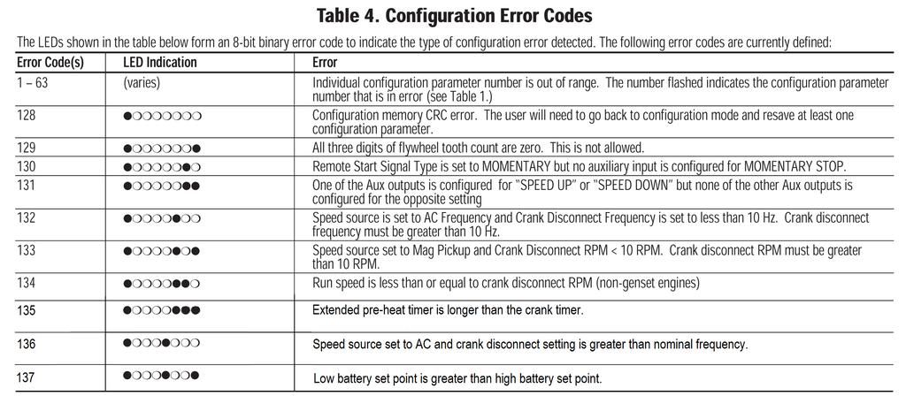
9 Error Mode Upon power up, when the DIP switch #1 is in the normal operating position (open position) and an error is detected in the user configuration, the Error Mode will be accessed. The LEDs will blink fast indicating the error. To correct the errors before the unit can operate in Engine Control Mode, the user will need to go back to Setup Mode. Table 3 Error Codes LED States and Table 4 Configuration Error Codes show the meaning of each LED state and configuration for the Error Mode. Sleep Mode In Auto Mode the Cascade will enter Sleep Mode after 2 minutes of inactivity. The unit will exit Sleep Mode on key press or remote call to run. It will not enter Sleep Mode if there is an active fault. NOTE: If PVA Gages are connected, Sleep Mode is not available
10 Installing the Cascade Auto-Start Controller The Cascade controller offers automatic start/stop control with easy configuration for a broad number of engine driven applications. Tools Needed To install the Cascade, the following tools are needed: #2 Philips (cross head) head screwdriver 5/16 Nut driver to fit #6-32 machine nuts Wire for hook-up (rising cage clamp suitable for gage wire) Mounting the Cascade WARNING Explosion Hazards This Equipment is suitable for use in Class I, Division 2, Groups A, B, C, and D or Non-hazardous locations only. Explosion Hazard Substitution of components may impair suitability for Class I, Division 2. Explosion Hazard Do not disconnect equipment while the circuit is live or make sure the area is known to be free of ignitable concentrations. NOTE: This unit shall be mounted in a Type 1 electrical enclosure (minimum requirement) for other than indoor applications

11 Cut a 5.63 x 4.06 in. (143 x 103mm) mounting hole, and drill four in. (4.3mm) diameter holes for the mounting screws. See Schematic below: Recommended Wiring Practices WARNING: For applications involving automatic start equipment, we strongly recommend the installation of an appropriate Emergency Stop safety device. The CASCADE is designed for pilot-duty use. Outputs should be connected to relays to pilot the loads. Wire the CASCADE controller with 18-gage stranded wire. 1. To help prevent electrical noise and voltage drop to the controller during cranking and preheat, wire the controller DC power connections directly to the cranking battery. This will also help improve Low battery starting capability. 2. When using a battery charger, it should be connected directly to the battery to help prevent electrical noise which could cause an engine ECU or associated equipment to operate erratically. 3. Never route low voltage DC wiring in the same conduit as high voltage AC wiring. Noise from electrical loads such as motors and variable frequency drives can be coupled into the engine ECU, governor, or associated equipment and may cause erratic operation. 4. Always use twisted shielded pair wires for the magnetic pickup wiring. Ground one end of the shield only
12 5. In spark ignited engine applications, always use resistive spark plugs and spark plug wires, as these greatly reduce the amount of radiated noise. 6. Always place a snubbing diode (sometimes also called a flyback, antikickback or reverse bias diode) directly across any inductive load. This helps eliminate a common source of electrical noise, as well as increases the operating lifetime of any solid-state output. 7. Always use twisted shielded pair communications wiring for RS-485 and SAE J1939 compliant wiring for J1939 communications. Make sure that terminating resistors (if required) have the correct rating and are installed properly. Typical Wiring Diagrams Cascade Basic Engine AC Speed Sensing
13 Cascade Basic Mechanical Engine MPU Speed Sensing
14 Cascade Basic ECU Engine ECU Speed Sensing
15 Inc/Dec Throttle (Manual), Line Fill Delay, Low Oil/Coolant Level, Preheat, Common Alarm
16 Mechanical Engine MPU Speed Source, Low Liquid Level Shutdowns Warmup-Cooldown Output
17 Mechanical Engine Winter/Summer Switch, Preheat Output, and Run & Idle Switch Output
18 Specifications Power input: 9-35VDC continuous - operates during total blackout for 2 sec. min. Power consumption: Sleep Mode (Manual): 2mA typical; (Automatic), 10mA typical. Running Mode (Manual): 45mA typical; (Automatic): 50mA typical. Operating/Storage temperature: -40 to 85 C; (-40 to 185 F). Humidity: 0-100%, non-condensing. Housing: UV stabilized black polycarbonate and epoxy encapsulation. Weather tight and includes sealing gasket to keep moisture and debris out of enclosure. Properly mounted controller will maintain NEMA4 / IP65 rating of enclosure. Vibration: Rated to 6G. Impact: Rated to 10G. Inputs: Dedicated digital inputs for low oil pressure, high engine temperature, remote start, DC charge fail/alternator fail. Two aux inputs are configurable for multiple functions. Outputs: 7 4 auxiliary, configurable (1A DC protected). 3 dedicated outputs for Crank, Fuel/ECU, Alternator excitation. Outputs are low side FET switches. Crank attempts: 3, 5, 10, Continuous. Crank Rest: 5-60 seconds, adjustable. Shutdown lockout time delay: 5, 10, 15, 20, 25, 30 seconds. Crank Disconnect speed setting: Field settable RPM (16-60Hz AC freq input). Overspeed/underspeed trip point setting: ±5 to 50% of nominal. Speed sensing inputs: Magnetic pickup (5-120VAC RMS / 0-10 khz) & AC frequency (30-600VAC RMS / Hz). CANbus interface: Directly reads engine speed, oil pressure, coolant temperature, system voltage, & engine status data* from SAE-J1939 enabled engines. MODbus interface: In J1939 applications drives PVA series analog gages. Gages limited to tach ( rpm), coolant temperature, oil pressure (0-100 & 0-150), DC volts (12v & 24v), AC freq, and audible alarm. *Engine status data limited to low oil pressure, high engine temperature, Wait to start status, Warning & Fault lamp information, and communication error
19
20
21
22
23

24
Flight Systems. Replacement for KASSEC DESCRIPTION
 DESCRIPTION The is a universal generator controller that will start, stop, and provide engine protection for most generators. Universal replacement for both the 90353 and 90354 KASSEC Compatible with most
GENSET CONTROL MODULE A121A / A241A
 Technical Data Sheet GENSET CONTROL MODULE A121A / A241A Features: Models for both 12V and 24V systems. One model for both spark ignition and diesel engines. 4-alarm light outputs with lamp-test provisions.
60 Series Engine Controls
 ECU 60 Series Engine Controls Use CAUTION since you are applying 120VAC RMS to the AC Input terminals and that it is always potentially their during engine run!!! ECU is a registered trademark of Engineering
GENSET CONTROL MODULE A121H / A241H. User selectable time delays for engine start and engine stop (cool down).
.") Technical Data Sheet GENSET CONTROL MODULE A121H / A241H Features: Models for both 12V and 24V systems. One model for both spark ignition and diesel engines. 4-alarm light outputs with lamp-test provisions.
Technical Data Sheet GENSET CONTROL MODULE A121H / A241H Features: Models for both 12V and 24V systems. One model for both spark ignition and diesel engines. 4-alarm light outputs with lamp-test provisions.
GENSET CONTROL MODULE LEVEL 1 A121CM / A241CM. Special logic to re-establish cranking following a false start.
 Technical Data Sheet GENSET CONTROL MODULE LEVEL 1 A121CM / A241CM Features: Models for both 12V and 24V systems. One model for both spark ignition and diesel engines. 5-alarm light outputs with lamp-test
DKG-114 MANUAL AND REMOTE START UNIT
 DKG-114 MANUAL AND REMOTE START UNIT FEATURES Both manual and remote controlled engine starting and stopping, Automatic shutdown on fault condition, Optional cooldown cycle on remote start operation, Optional
1. AC VOLTS: Displays generator output in voltage. 2. AC FREQUENCY: Displays the speed of the generator set in Hertz.
 1. AC VOLTS: Displays generator output in voltage. 2. AC FREQUENCY: Displays the speed of the generator set in Hertz. 3. AMMETER/PERCENT OF LOAD: Displays the load on the generator in amps or in percentage.
ANALOG CONTROL PANEL
 ANALOG CONTROL PANEL 1. AC VOLTS: Displays generator output in voltage. 2. AC FREQUENCY: Displays the speed of the generator set in Hertz. 3. Percent of Load: Displays percentage of load on the generator.
Model H30 Operation Manual
 Model H30 Operation Manual Model H30 Version 1.0 August 1, 2007 2 135 West Davenport Street Rhinelander WI 54501 Phone: 866.441.7997 Fax: 866.278.0036 info@houstonst.com www.houstonst.com 3 Table of Contents
GENSET CONTROL MODULE LEVEL 0 A120A. User selectable time delays for engine start and engine stop (cool down).
.") Technical Data Sheet GENSET CONTROL MODULE LEVEL 0 A120A Features: One model for both spark ignition and diesel engines. 4-alarm light outputs with automatic lamp-test provision. Overspeed adjustment not
Technical Data Sheet GENSET CONTROL MODULE LEVEL 0 A120A Features: One model for both spark ignition and diesel engines. 4-alarm light outputs with automatic lamp-test provision. Overspeed adjustment not
TG350 User Manual. Manual Revision: Min. FW Revision: Date Released: 09/01/ DYNAGEN Technologies Inc
 TG350 User Manual Manual Revision: 1.4.0 Min. FW Revision: 1.42.01 Date Released: 09/01/2014 Table of Contents 1 Introduction 1.1 Specifications... 3 2 Installation 2.1 Terminal s... 6 2.2 Typical Wiring...
HGM1780. Automatic Genset Controller USER MANUAL. Smartgen Technology
 HGM1780 Automatic Genset Controller USER MANUAL Smartgen Technology Smartgen Technology Co., Ltd No. 28 Jinsuo Road Zhengzhou Henan Province P. R. China Tel: 0086-371-67988888/67981888 0086-371-67991553/67992951
MD10. Engine Controller. Installation and User Manual for the MD10 Engine Controller. Full Version
 MD10 Engine Controller Installation and User Manual for the MD10 Engine Controller. Full Version File: MartinMD10rev1.4.doc May 16, 2002 2 READ MANUAL BEFORE INSTALLING UNIT Receipt of shipment and warranty
5220 AUTOMATIC MAINS FAILURE MODULE OPERATING MANUAL
 5220 AUTOMATIC MAINS FAILURE MODULE OPERATING MANUAL > Section DSE Model 5220 Automatic Mains Failure & Instrumentation System Operators Manual TABLE OF CONTENTS
HGM1780 AUTOMATIC GENERATOR MODULE CONTENT 1. SUMMARY PERFORMANCE AND CHARACTERISTICS SPECIFICATION OPERATION...
 CONTENT 1. SUMMARY...4 2. PERFORMANCE AND CHARACTERISTICS...4 3. SPECIFICATION...5 4. OPERATION...6 4.1. DISPLAY PANEL...6 4.2. LCD ICON INSTRUCTION...7 4.3. DISPLAY INSTRUCTIONS...7 4.4. DISPLAY DESCRIPTION...8
HGM1770 Automatic Generator Control Module OPERATING MANUAL Smartgen Electronic
 HGM1770 Automatic Generator Control Module OPERATING MANUAL Smartgen Electronic CONTENT 1. SUMMARY... 4 2. PERFORMANCE AND CHARACTERISTICS... 4 3. SPECIFICATIONS... 5 4. OPERATION... 6 5. PROTECTION...
ORDERING INFORMATION SPECIFICATIONS APPLICATION
 ORDERING INFORMATION UNIVERSAL MODELS The ordering part number for the universal model is 82UNIVERSAL. The 82UNIVERSAL comes with remote flame sense active. For internal flame sense, the supplied universal
MODEL 520 REMOTE START ENGINE MANAGEMENT SYSTEM
 MODEL 520 REMOTE START ENGINE MANAGEMENT SYSTEM DSE 520 ISSUE 4 4/4/02 MR 1 TABLE OF CONTENTS Section Page INTRODUCTION... 4 CLARIFICATION OF NOTATION USED WITHIN THIS PUBLICATION.... 4 1. OPERATION...
ENGEN -100/ENGEN -200 ENGINE GENERATOR CONTROLLER
 ENGEN -100/ENGEN -200 ENGINE GENERATOR CONTROLLER The engine/generator controller is an integrated genset controller contained in a single, easy to install package. The controller contains a microprocessor-based
GSC400 Series. Automatic Gen-Set Controller Manual. Revision 2.6
 GSC400 Series Automatic Gen-Set Controller Manual Revision 2.6 GSC400 Automatic Gen-Set Controller Installation and User Manual MAN-0076 Rev2.6, GSC400 User Manual.doc, May 2010 2 of 105 Thank You For
ES52. Auto Start Engine Controller. Full Version. Installation and User Manual for the ES52 Auto Start Engine Controller.
 ES52 Auto Start Engine Controller Installation and User Manual for the ES52 Auto Start Engine Controller. Full Version File: MAN-0001 R4.0, ES52 User Manual.doc Date: August 2017 Thank You For Purchasing
702 AUTOMATIC START MODULE OPERATING INSTRUCTIONS
 702 AUTOMATIC START MODULE OPERATING INSTRUCTIONS > TABLE OF CONTENTS 1 DESCRIPTION OF OPERATION... 4 1.1 MANUAL MODE OPERATION... 4 1.2 AUTOMATIC MODE OF OPERATION...
Generator Start Control Module
 Generator Start Control Module Part# GSCM-mini-i ATKINSON ELECTRONICS, INC. 14 West Vine Street Murray, Utah 84107 Contact cbdsales@atkinsonel.com for the proper hookup diagram. Please include the generator
Section 3 Technical Information
 Section 3 Technical Information In this Module: Engine identification Modes of operation Battery charging and heat manage operation Service and repair procedures Maintenance requirements Engine Identification
HGM72 Automatic Generator Module OPERATING MANUAL Smartgen Electronic
 HGM72 Automatic Generator Module OPERATING MANUAL Smartgen Electronic CONTENT 1 SUMMARY... 4 2 FEATURES... 4 3 SPECIFICATION... 4 4 DISPLAY SYMBOL AND OPERATION... 5 5 ALARM... 7 6 PARAMETERS TABLE (ONLY
DEEP SEA ELECTRONICS PLC
 COMPLEX SOLUTIONS MADE SIMPLE. DEEP SEA ELECTRONICS PLC DSE710 AUTOSTART CONTROL MODULE OPERATING MANUAL Deep Sea Electronics Plc Highfield House Hunmanby North Yorkshire YO14 0PH ENGLAND Sales Tel: +44
Generator Start Control Module
 Generator Start Control Module Part# GSCM-mini-o ATKINSON ELECTRONICS, INC. 14 West Vine Street Murray, Utah 84107 Contact cbdsales@atkinsonel.com for the proper hookup diagram. Please include the generator
Observe all necessary safety precautions when controlling the soft starter remotely. Alert personnel that machinery may start without warning.
 Introduction OPERATING INSTRUCTIONS: MCD REMOTE OPERATOR Order Codes: 175G94 (for MCD 2) 175G361 + 175G9 (for MCD 5) 175G361 (for MCD 3) 1. Introduction 1.1. Important User Information Observe all necessary
ES52 Auto Start Engine Controller Installation and User Manual for the ES52 Auto Start Engine Controller.
 ES52 Auto Start Engine Controller Installation and User Manual for the ES52 Auto Start Engine Controller. Full Version File: ES52rev2.63.doc October 24, 2006 2 Thank You For Purchasing This DynaGen Product
PowerCommand 1.1 control system
 Specification sheet PowerCommand 1.1 control system Description The PowerCommand control system is a microprocessor-based generator set monitoring, metering and control system designed to meet the demands
PowerView PV380-R2 Mechanical Configuration
 PowerView PV380-R2 Mechanical Configuration Operations Manual *Products covered in this document comply with European Council electromagnetic compatibility directive 2004/108/EC and electrical safety directive
DIESEL Engine Fire Pump Controllers Features
 1-1 Printer / Recorder The industrial grade thermal printer is housed in a rugged steel enclosure within the controller. The on/off switch, feed and reset buttons are front accessible. A bi-color status
iguard Digital Generator Set Controller Installation and Operations Manual Section 75
 iguard Digital Generator Set Controller Installation and Operations Manual 00-02-0522 09-24-12 Section 75 In order to consistently bring you the highest quality, full featured products, we reserve the
EDG6000 Electronic Digital Governor
 INTRODUCTION GAC s digital governor is designed to regulate engine speed on diesel and gaseous fueled engines. When paired with a GAC actuator the EDG is a suitable upgrade for any mechanical governor
ECU-02 Ver2.1 Automatic Engine Control Unit Operators Manual
 ECU-02 Ver2.1 Automatic Engine Control Unit Operators Manual Headquarters : No.3, Lane 201, Chien Fu St., Chyan Jenn Dist., Kaohsiung, TAIWAN Tel : + 886-7-8121771 Fax : + 886-7-8121775 URL : http://www.kutai.com.tw
Te 803 Electronic Controller. Service, Operation & Technical Information Manual
 Te 803 Electronic Controller Service, Operation & Technical Information Manual WARNING! Technical descriptions and data given in this document are accurate, to the best of our knowledge, but can be subject
Deep Sea Electronics Plc
 Deep Sea Electronics Plc 5120 AUTOMATIC MAINS FAILURE MODULE OPERATING MANUAL Author: Anthony Manton Deep Sea Electronics Plc Highfield House Hunmanby North Yorkshire YO14 0PH England Tel: +44 (0) 1723
Spark-ignited generator set
 Specification sheet Spark-ignited generator set 20-40 kw EPA emissions Description Cummins generator sets are fully integrated power generation systems providing optimum performance, reliability and versatility
GENSET PRODUCTS 013 2
 GENSET PRODUCTS 2013 TECHNOLOGY IS NOW FOR EVERYONE D 700 COMMUNICATION CAPABILITIES AUTOMATIC MAINS FAILURE UNITS DKG 107 DKG 107 The lowest cost AMF module Factory set timers Adjustable AC low voltage
DEEP SEA ELECTRONICS PLC
 COMPLEX SOLUTIONS MADE SIMPLE DEEP SEA ELECTRONICS PLC DSE720 AUTOSTART CONTROL MODULE OPERATING MANUAL http://bestgenerator.spb.ru/?page_id=6765 Deep Sea Electronics Plc Highfield House Hunmanby North
HGM6320T AUTOMATIC GENERATOR CONTROLLER USER MANUAL
 HGM6320T AUTOMATIC GENERATOR CONTROLLER USER MANUAL Smartgen Technology CONTENT 1 SUMMARY... 4 2 PERFORMANCE AND CHARACTERISTICS... 4 3 SPECIFICATION... 5 4 OPERATION... 6 4.1 LCD DISPLAY... 6 4.2 KEY
GSC400 Series. Automatic Gen-Set Controller Manual. Revision 2.5
 GSC400 Series Automatic Gen-Set Controller Manual Revision 2.5 GSC400 Automatic Gen-Set Controller Installation and User Manual Full Version File: GSC400 User Manual Rev2.5.doc, December 2009 2 of 98 Thank
Murphy-Link Series Panels Models ML25, ML50, ML100 ML150, and ML300. Installation and Operations Manual Section 30
 Murphy-Link Series Panels Models ML25, ML50, ML100 ML150, and ML300 Installation and Operations Manual 00-02-0842 2012-07-06 Section 30 In order to consistently bring you the highest quality, full featured
Application Engineering
 Application Engineering February, 2009 Copeland Digital Compressor Controller Introduction The Digital Compressor Controller is the electronics interface between the Copeland Scroll Digital Compressor
Energy Division
 Energy Division http://energy.tycoelectronics.com Installation and Operating Manual GEN-TRANS Automatic Generator Transfer Switch Controller with Metering Tyco Electronics UK Limited Crompton Instruments
HGM6400 Automatic Genset Controller (With J1939 Interface) USER MANUAL Smartgen Technology
 USER MANUAL Smartgen Technology") HGM6400 Automatic Genset Controller (With J1939 Interface) USER MANUAL Smartgen Technology Chinese trademark English trademark Smartgen make your generator smart Smartgen Technology Co., Ltd No. 28 Jinsuo
HGM6400 Automatic Genset Controller (With J1939 Interface) USER MANUAL Smartgen Technology Chinese trademark English trademark Smartgen make your generator smart Smartgen Technology Co., Ltd No. 28 Jinsuo
DEEP SEA ELECTRONICS PLC
 DEEP SEA ELECTRONICS PLC 703 AUTOMATIC START MODULE OPERATING INSTRUCTIONS Author:- John Ruddock 703 Operating Instructions Issue Beta1 25/08/2003 2:45 PM JR - 1 - >
Installation Instructions
 Smart Start Assist Kit For use with Single-Phase Residential Geothermal Heat Pumps 8-733-934-497 Installation Instructions NOTE: Read the entire instruction manual before starting the installation. SAFETY
ICON 2 1. FEATURES AND CHARACTEIRICS
 ICON 2 1. FEATURES AND CHARACTEIRICS High end Micro-controller(DSP) technology Wide range of auxiliary supply: 7V to 45Vdc. Low power Consumption : 200 ma @ 12 V DC. Alphanumeric 16X4 or 16X2 LCD display
PSM72H Push-Button Start Module
 Capricorn Controls DA02PSM72H1-2 Data & Application Note Page 1 of 6 PSM72H Push-Button Start Module Genset Controls - Timers/Monitors/Trips - Battery Charging Spares & Accessories - Custom Products Ultra
Generator Sets Controller 210. Operation Manual. Ver1.0
 Generator Sets Controller 210 Operation Manual Ver1.0 Note This information could include technical inaccuracies or typographical error. Manufacturer may make improvements and/or changes in the product(s)
PRODUCT SERIES: DPG-2100
 Service Information PRODUCT SERIES: DPG-2100 DYNA Programmable Governor for Isochronous Generators Calibration and Troubleshooting for DPG-2101, DPG-2102, DPG-2103, DPG-2104 DPG-2100 The DPG-2100 governors
Diesel generator set QSB7 series engine
 Specification sheet Diesel generator set QSB7 series engine 100 200 kw 60Hz Description Cummins commercial generator sets are fully integrated power generation systems providing optimum performance, reliability
HGM6320T AUTOMATIC GENERATOR CONTROLLER USER MANUAL
 HGM6320T AUTOMATIC GENERATOR CONTROLLER USER MANUAL Smartgen Technology Smartgen Technology Co., Ltd No. 28 Jinsuo Road Zhengzhou Henan Province P. R. China Tel: 0086-371-67988888/67981888 0086-371-67991553/67992951/67992952
DEEP SEA ELECTRONICS PLC
 COMPLEX SOLUTIONS MADE SIMPLE. DEEP SEA ELECTRONICS PLC DSE5220 AUTO MAINS FAILURE MODULE OPERATING MANUAL Deep Sea Electronics Plc Highfield House Hunmanby North Yorkshire YO14 0PH ENGLAND Sales Tel:
Spark-ignited generator set
 Specification sheet Spark-ignited generator set 85 100 kw Standby EPA emissions Description Cummins commercial generator sets are fully integrated power generation systems providing optimum performance,
QGP Allegro Bus (Tiffin's ECM Template)
") ISL9 EPA 2010 CM2250 Accelerator Interlock Accelerator Options Dual Accelerator Remote Accelerator Pedal or Lever Adjustable Low Air Speed Low Idle Speed Low Idle Speed Adjustment Switch Aftertreatment
ISL9 EPA 2010 CM2250 Accelerator Interlock Accelerator Options Dual Accelerator Remote Accelerator Pedal or Lever Adjustable Low Air Speed Low Idle Speed Low Idle Speed Adjustment Switch Aftertreatment
ECU. Speed Switch Manual. Contents. ECU is a registered trademark of Engineering Concepts Unlimited Inc.
 ECU Speed Switch Manual Contents ECU is a registered trademark of Engineering Concepts Unlimited Inc. Contents Unit review Magnetic pickup example AC input example Design Guide Troubleshooting guide 24
Application Engineering
 Application Engineering March 2011 Copeland Digital Compressor Controller Introduction The Digital Compressor Controller is the electronics interface between the Copeland Scroll Digital compressor or the
DEEP SEA ELECTRONICS PLC
 COMPLEX SOLUTIONS MADE SIMPLE. DEEP SEA ELECTRONICS PLC DSE5110 AUTOSTART CONTROL MODULE OPERATING MANUAL Deep Sea Electronics Plc Highfield House Hunmanby North Yorkshire YO14 0PH ENGLAND Sales Tel: +44
AUTOSTART 705S V1.00 AUTOSTART 710S / 720S / 730S V1.04 Programming Reference and Check Sheets
 The Generator Controls Division of Frank W. Murphy AUTOSTART 705S V1.00 AUTOSTART 710S / 720S / 730S V1.04 Programming Reference and Check Sheets MODEX AUTOMATION FRANK W. MURPHY LTD. Church Road Laverstock
GSC300. Auto Start Engine Controller. Installation and User Manual for the GSC300 Auto Start Engine Controller. Full Version
 GSC300 Auto Start Engine Controller Installation and User Manual for the GSC300 Auto Start Engine Controller Full Version File: GSC300rev2.4.doc Dec. 08, 2005 2 Thank You For Purchasing This DynaGen Product
Automatic Genset Controller, AGC-4 Display readings Push-button functions Alarm handling Log list
 OPERATOR'S MANUAL Automatic Genset Controller, AGC-4 Display readings Push-button functions handling Log list DEIF A/S Frisenborgvej 33 DK-7800 Skive Tel.: +45 9614 9614 Fax: +45 9614 9615 info@deif.com
SOLAR LIGHTING CONTROLLER SUNLIGHT MODELS INCLUDED IN THIS MANUAL SL-10 SL-10-24V SL-20 SL-20-24V
 SOLAR LIGHTING CONTROLLER OPERATOR S MANUAL SUNLIGHT MODELS INCLUDED IN THIS MANUAL SL-10 SL-10-24V SL-20 SL-20-24V 10A / 12V 10A / 24V 20A / 12V 20A / 24V 1098 Washington Crossing Road Washington Crossing,
HGM72 Automatic Generator Module OPERATING MANUAL Smartgen Electronic
 HGM72 Automatic Generator Module OPERATING MANUAL Smartgen Electronic Smartgen Electronic Equipment Co., Ltd No.28 Jinsuo Road Zhengzhou Henan Province P.R.China Tel: 0086-371-67988888/67981888 0086-371-67991553/67992951/67992952
INSTRUCTION AND USE MANUAL
 CONTROL UNITS FOR ENGINE CONTROL AND PROTECTION TYPE CEP-090 INSTRUCTION AND USE MANUAL It is equipped with display to show the INSTRUMENTS: - hour-meter - fuel level indicator - tachometer - battery voltmeter
DEEP SEA ELECTRONICS PLC DSE3210 Configuration Suite Software Manual
 DEEP SEA ELECTRONICS PLC DSE3210 Configuration Suite Software Manual Document Number 057-152 Author : Paul Gibbons DSE3210 Configuration Suite Software Manual Issue 1 DSE3210 Configuration Suite Software
USERS MANUAL MCD REMOTE OPERATOR
 USERS MANUAL MCD REMOTE OPERATOR Order Code: 175G9004, 175G3061 Contents Contents Introduction...2 Important User Information...2 General Description...2 Symbols Used in this Manual...2 Installation...3
Rental Power QSL9 series engine
 Specification sheet Rental Power QSL9 series engine 250 kva - 300 kva 50 Hz 225 kw - 275 kw 60 Hz Description This Cummins commercial generator set is a fully integrated power generation system, providing
E.S.P. Embedded Sensing Probes for Motor Brushes
 E.S.P. Embedded Sensing Probes for Motor Brushes 2/13 Installation & Operating Manual MN609 Any trademarks used in this manual are the property of their respective owners. Important: Be sure to check www.baldor.com
TG350 User Manual. Manual Revision: Min. FW Revision: Date Released: 18/12/ DynaGen Technologies Inc
 TG350 User Manual Manual Revision: 6.0.0 Min. FW Revision: 1.82.09 Date Released: 18/12/2017 TG350 User Manual Table of Contents User Guide 1 Introduction 4... 4 1.1 Specifications 2 Installation 6...
IMI vibration switch USER MANUAL INSTALLATION - OPERATION - MAINTENANCE
 USER MANUAL IMI vibration switch INSTALLATION - OPERATION - MAINTENANCE Z0929039_A ISSUED 03/2017 READ AND UNDERSTAND THIS MANUAL PRIOR TO OPERATING OR SERVICING THIS PRODUCT. contents Overview General
GUARD-LITE SERIES EMERGENCY UNIT EQUIPMENT
 GUARD-LITE SERIES EMERGENCY UNIT EQUIPMENT Service Questions Call: 910-259-1131 IMPORTANT SAFEGUARDS CLASS I DIV 2 HAZARDOUS LOCATION GROUPS A, B, C, AND D ZONE 2 GROUPS IIC, IIB AND IIA CLASS II DIV 2
WARNING. Diode Package The Murphy diode package ( ) is designed to allow the fuel shutoff valve to be used with dual Magneto Ignition systems.
 is designed to allow the fuel shutoff valve to be used with dual Magneto Ignition systems.") M2582, M508, and M580 Series Electromechanical and Pneumatic, Fuel Gas Shutoff Valves Installation and Operation Instructions Please read the following instructions before installing. A visual inspection
M2582, M508, and M580 Series Electromechanical and Pneumatic, Fuel Gas Shutoff Valves Installation and Operation Instructions Please read the following instructions before installing. A visual inspection
Low Pressure Sensor. Overview. Specifications. Installation and Operation
 Overview The Low Pressure Sensor with display measures building pressure, air velocities and volumes. The heart of the unit is a micro-machined silicon pressure sensor. The unit includes a static pressure
GCU-10. Automatic Engine Control Unit Operators Manual
 GCU-10 Automatic Engine Control Unit Operators Manual KUTAI ELECTRONICS INDUSTRY CO., LTD. TEL : +886-7-8121771 FAX : +886-7-8121775 Website : www.kutai.com.tw Headquarters : No.3, Lane 201, Chien Fu St.,
Diesel generator set QSX15 series engine
 Specification sheet Diesel generator set QSX15 series engine 410 kw 455 kw 60 Hz Data Center Continuous EPA Emissions Description Cummins commercial generator sets are fully integrated power generation
HGM6410/6420. Automatic Generator Module. With J1939 Interface OPERATING MANUAL. Smartgen Electronics
 HGM6410/6420 Automatic Generator Module With J1939 Interface OPERATING MANUAL Smartgen Electronics Smartgen Electronic Equipment Co,.Ltd No.12 Dongqing Street Zhengzhou Henan Province P.R.China Tel : (0086)-371-67992951
Generator Set Applications FT-10 Network Control Communications Module (CCM-G) Kit
 Kit") Instruction Sheet 10 2004 Generator Set Applications FT-10 Network Control Communications Module (CCM-G) Kit 541 0810 GENERAL INFORMATION This kit contains one Control Communications Module (CCM-G) with
Instruction Sheet 10 2004 Generator Set Applications FT-10 Network Control Communications Module (CCM-G) Kit 541 0810 GENERAL INFORMATION This kit contains one Control Communications Module (CCM-G) with
HGM6310D/6320D AUTOMATIC GENERATOR MODULE USER MANUAL
 HGM6310D/6320D AUTOMATIC GENERATOR MODULE USER MANUAL SMARTGEN ELECTRONIC CONTENT 1 SUMMARY... 4 2 PERFORMANCE AND CHARACTERISTICS... 4 3 SPECIFICATION... 6 4 OPERATION... 7 4.1 KEY FUNCTION... 7 4.2 AUTOMATIC
Diesel generator set. QSB5 series engine Hz EPA Tier 3 emissions. Specification sheet. Description. Features
 Specification sheet Diesel generator set QSB5 series engine 50-125 kw @ 60 Hz EPA Tier 3 emissions Description Cummins generator sets are fully integrated power generation systems providing optimum performance,
SE-3SCR-LM MANUAL MOTOR LOAD MANAGER
 3714 Kinnear Place Saskatoon, SK Canada S7P 0A6 Ph: (306) 373-5505 Fx: (306) 374-2245 www.littelfuse.com/relayscontrols SE-3SCR-LM MANUAL MOTOR LOAD MANAGER MARCH 5, 2013 REVISION 4 MOTOR LOAD MANAGER
TG410 User Manual. Manual Revision: Min. FW Revision: Date Released: 18/12/ DynaGen Technologies Inc
 TG410 User Manual Manual Revision: 6.0.0 Min. FW Revision: 1.82.09 Date Released: 18/12/2017 TG410 User Manual Table of Contents User Guide 1 Introduction 4... 5 1.1 Specifications 2 Installation 6...
DEEP SEA ELECTRONICS
 DEEP SEA ELECTRONICS DSE6010 MKII / DSE6020 MKII Configuration Suite PC Software Manual Document Number: 057-223 Author: Fady Atallah DSE6010 MKII / DSE6020 MKII Configuration Suite PC Software Manual
PRESSURE GOVERNOR, ENGINE MONITORING, AND MASTER PRESSURE DISPLAY MODEL: TCA100
 Document Number: XE-TCA1PM-R0A TCA100 Rev0511 PRESSURE GOVERNOR, ENGINE MONITORING, AND MASTER PRESSURE DISPLAY MODEL: TCA100 FIRE RESEARCH CORPORATION www.fireresearch.com 26 Southern Blvd., Nesconset,
Diesel generator set 6BT5.9 series engine
 Specification sheet Diesel generator set 6BT5.9 series engine 85 kw - 100 kw Standby Description Cummins commercial generator sets are fully integrated power generation systems providing optimum performance,
DEEP SEA ELECTRONICS PLC
 COMPLEX SOLUTIONS MADE SIMPLE DEEP SEA ELECTRONICS PLC DSE704 AUTOSTART CONTROL MODULE OPERATING MANUAL 057-042 704 Operating Instructions Issue 2.1 18/06/2007 11:27:00 JR - 1 - Deep Sea Electronics Plc
PRODUCT INFORMATION BULLETIN
 724-283-4681 724-283-5939 (fax) PRODUCT INFORMATION BULLETIN DESCRIPTION The, Model 10-7100 is one in a series of critical speed switches that monitor speed and detect motion in all types of machinery
DEEP SEA ELECTRONICS DSE7110 MKII / DSE7120 MKII Configuration Suite PC Software Manual
 DEEP SEA ELECTRONICS DSE7110 MKII / DSE7120 MKII Configuration Suite PC Software Manual Document Number 057-185 Author: Fady Atallah DSE7110 MKII / DSE7120 MKII Configuration Suite PC Software Manual DSE7110
C.E. Niehoff & Co. C840D Alternator Troubleshooting Guide CAUTION. Testing Guidelines. Hazard Definitions WARNING.
 C.E. Niehoff & Co. C840D Alternator Troubleshooting Guide WARNING Before troubleshooting any CEN products, the service technician should: read, understand, and agree to follow all information contained
Deep Sea Electronics Plc
 Deep Sea Electronics Plc 5520 Operators Manual Author Tony Manton Deep Sea Electronics Plc Highfield House Hunmanby Industrial Estate North Yorkshire YO14 0PH ENGLAND Tel +44 (0) 1723 890099 Fax +44 (0)
ENGINE PROTECTION BOARD PDM1
 ENGINE PROTECTION BOARD REFERENCE MANUAL. Standard of reference: IEC/EN 60255-6 IEC/EN 61000-4-2 IEC/EN 61000-4-3 IEC/EN 61000-4-4, IEC/EN 61000-4-5 IEC/EN 61000-4-6 IEC/EN 55011 IEC/EN 60028-2-61 IEC/EN
DG SYNCHRONIZING &AMF PANEL
 A 80, Sector 80, Phase 2, Noida 201305, Utter Pradesh, India DG SYNCHRONIZING &AMF PANEL Clients Bharat Petroleum Corp.Ltd PROJECT- DG Synchronization panel with AMF function. Design BY:- Errection By
User Manual Solar Charge Controller 3KW
 User Manual Solar Charge Controller 3KW Version: 1.3 CONTENTS 1 ABOUT THIS MANUAL... 1 1.1 Purpose... 1 1.2 Scope... 1 1.3 SAFETY INSTRUCTIONS... 1 2 INTRODUCTION... 2 2.1 Features... 2 2.2 Product Overview...
Tachometers and Tach/Hourmeters AT and ATH Series
 Tachometers and Tach/Hourmeters AT and ATH Series Installation Instructions 00-02-0986 Section 70 IMPORTANT! These instructions are specific to tachometer models with a single calibration push button.
N1387 Series Troubleshooting Guide for N Alternators
 N1387 Series Troubleshooting Guide for N1387-1 Alternators Hazard Definitions These terms are used to bring attention to presence of hazards of various risk levels or to important information concerning
INSTRUCTION MANUAL FOR. VOLTAGE REGULATOR Model: APR Part Number:
 INSTRUCTION MANUAL FOR VOLTAGE REGULATOR Model: APR 125-5 Part Number: 9 1688 00 100 Publication Number: 9 1688 00 990 Revision H: 07/2001 CONTENTS SECTION 1 GENERAL INFORMATION...1-1 DESCRIPTION... 1-1
4.2 Component Identification
 Digital Control Panels Deep Sea Electronics 5220 4.1 General 4.2 Component Identification 4.3 The YML5220 Controller 4.4 Description of Controls 4.5 Navigation 4.5.1 General Navigation 4.5.2 The Event
Automatic Transfer Switch FT-10 Network Control Communications Module (CCM-T) Kit
 Kit") Instruction Sheet 10-2004 Automatic Transfer Switch FT-10 Network Control Communications Module (CCM-T) Kit 541 0811 PURPOSE OF KIT A CCM-T is used to monitor and control an automatic transfer switch.
Instruction Sheet 10-2004 Automatic Transfer Switch FT-10 Network Control Communications Module (CCM-T) Kit 541 0811 PURPOSE OF KIT A CCM-T is used to monitor and control an automatic transfer switch.
EPM72 Engine Protection Module
 Capricorn Controls DA01EPM1-1 Data & Application Note Page 1 of 8 EPM2 Engine Protection Module Genset Controls - Timers - Monitors - Trips - Battery Charging - Spares & Accessories - Custom Products All