RapidLED NanoCube 24 Aurora Array Retrofit
|
|
|
- Beverley Melton
- 6 years ago
- Views:
Transcription
1 1 RapidLED NanoCube 24 Aurora Array Retrofit Contents Overview... 1 Hood Preparation... 2 Hood Power Wiring Preparation... 3 Fan and AC Adapter Wiring... 5 Heatsink Installation Aurora LED Array Specifications Wiring the Aurora Puck Wiring the Aurora LED Array to Drivers Wiring the Driver to AC Power RapidLED Nano Drivers with Potentiometer (Skip if you have any other driver): Mean Well LDD Drivers (Skip if you have any other driver): Wiring Power Cord to Power Supply Wiring LDD Drivers to Power Supply Connecting LDD Drivers to LED Strings Finishing Up Overview As with any type of lighting retrofit, there are many dangers, difficulties, and pitfalls that may occur. The Nano Cube 24 retrofit should be attempted by people familiar with AC power and wiring, electronics, LEDs, LED Drivers, series circuits, and be comfortable with the fact that this retrofit will require complete disassembly and removal of all contents of the original hood. If you are uncomfortable with or inexperienced at any of the prerequisites required for this retrofit, you should not attempt this retrofit. NOTE: These instructions are for installing the Aurora array in your hood. If you are using the kit with individual LEDs, refer to the instructions located here: JBJ Nanocube 24 Instructions


2 2 Hood Preparation Any and all power wires must be unplugged and disconnected before beginning. We will keep the original fans and the two large wires coming out of the rear of the hood. Everything else will be removed. Start: Reflectors Removed: Switch Removal:


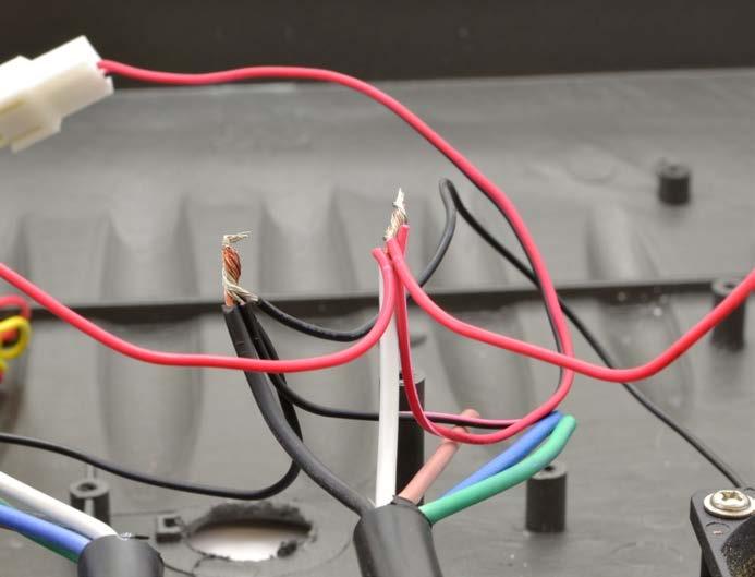
3 3 To remove the switch, press in with a flat blade screwdriver at the edges as indicated by the arrows and gently wiggle it out of the socket. You will have to remove the red wiring to get it out of the hood. Finish: Hood Power Wiring Preparation We will be utilizing one of the original (two rear) power wires in the hood. Remove the other power cable, the hole will be used to run the driver jumpers from the array to the drivers. First step is to strip off about inches of the outermost jacket material from the end of the wire do not strip the ends off of any of the individual wires yet. Be sure you do not damage or cut the protective jacket of

: 4 Next, we do")
4 the inner wires when stripping off the black power wire jacket that encompasses the 5 inner wires. You can cut off the brown, blue and green wires, they will not be used in this installation (hood shown below has two cables, your hood will have one): 4 Next, we do the same for the opposite end of the power wire: First, cut the end off of the power wire:

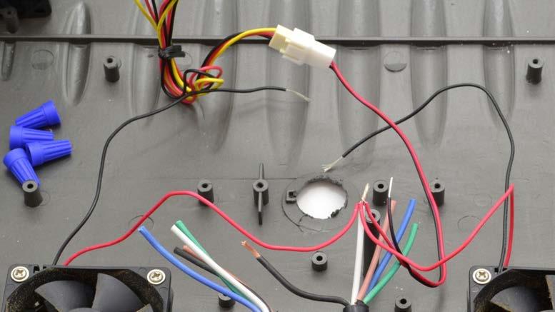
5 Next, strip off the outermost jacket that encompasses the 5 inner wires, being careful to not damage or cut any of the inner 5 wires (hood shown below has two cables, your hood will have one). You can cut off the blue, green and brown wires: 5 Fan and AC Adapter Wiring In this step we will install the fans. We will use the original fans and add one additional fan for cross-flow ventilation. For wiring, we will wire the included AC adapter to one of the original power wires and then wire the fans to the same wire. The final result has an AC adapter attached to one end and 3 fans attached to the other. Step 1: Cut off the original fan connectors and strip each fan wire. Do this for both original fans.

, the black wire is negative (-).")

6 6 Step 2: The Vantec fan includes an adapter. Cut the end off of it and strip a little bit of wire off of each end. The red wire is positive (+), the black wire is negative (-). Step 3: Cut the end off of the AC adapter. Step 4: Strip a little bit of wire off of the end of the AC adapter wire. Note which wire is positive on the AC adapter and which wire is negative.


 white wire from the power cable, 2) red wire from the 1 st original fan, 3) red wire")
7 7 No dashes indicate negative ( ) AC adapter wire White dashes indicate positive (+) AC adapter wire Step 5: In this step, use the original power cable bundle to wire the fans. We chose the right cable bundle (with the back of the hood facing our body). Within the right cable, we used the white wire as + and the black wire as -. Once you decide which wires you will use, strip off both ends of each wire. Step 6: Now we wire the fan cables together. Take one of the included wire nuts and wire the four positive (+) wires together. The wires are: 1) white wire from the power cable, 2) red wire from the 1 st original fan, 3) red wire from the 2 nd original fan, 4) red wire from the Vantec fan adapter. After we wire the reds, we do the same for all black fan wires, connecting them to the black power wire with a wire nut.
8 8

 and should be wired together.")
9 Step 7: Now that the inside wiring is done, we will wire the AC adapter to the outside wires. Simply wire nut the positive and negative wires together. In our example the white power wire and the dashed wire from the AC adapter are positive (+) and should be wired together. The negative (-) wires are the black power wire and the AC adapter non-dashed wire. 9

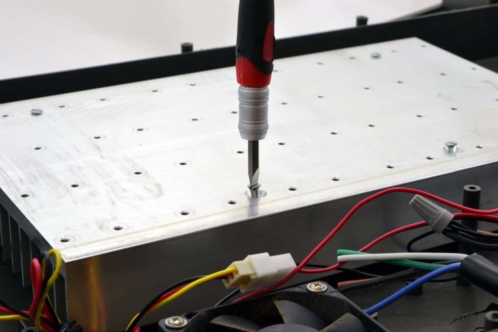
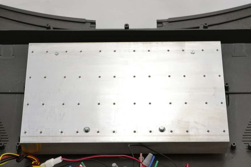
10 10 Your fans are now completely wired. If you want, try them out and make sure they work! Heatsink Installation The heatsink attaches to the plastic posts already in the hood via 4 screws. The screws are the large screws included with the kit. Tighten gently until heatsink is snug. Tightening them more than this may strip out the plastic screw bosses in the hood at which point you will have fill the stripped bosses with a hard glue or epoxy and drill them back out so the screw will grip again or find some other solution. Over tightening may also snap the screw bosses from the hood, in which case, you will have to attempt repair with super glue.
11 11
 - 4 XP-G Cool White o UV (700mA max) 4 SemiLEDs Violet UV Wiring the Aurora Puck In this step, we will connect")

12 12 Aurora LED Array Specifications The Array has 4 channels: o Blue (1000mA max) - 4 XT-E Royal Blue + 3 XP-E Blue o Color (700mA max) - 2 XP-E Green + 1 XP-E Blue + 2 XP-E Red + 1 XP-E Red-Orange o White (1500mA max) - 4 XP-G Cool White o UV (700mA max) 4 SemiLEDs Violet UV Wiring the Aurora Puck In this step, we will connect the driver jumpers and terminal plugs to the array. First, insert 4 terminal plugs into the 2-pin sockets on the edge labeled Connect to second array or Plug before Applying Power. They will snap in and be difficult to remove if fully inserted. Give them a little tug (monkey tug, not gorilla tug) to ensure they do not fall out.
 and ensure they do not fall out.")

13 Next, on the opposite end, insert one driver jumper into each of the 2-pin sockets on the edge labeled with the colors Blue, Color, White, and UV. As with the terminal plugs, these should snap in and not fall out. Give them a gentle tug (monkey tug, not gorilla tug) and ensure they do not fall out. 13 Attaching Aurora LED Array to Heatsink To attach the Aurora LED Array to the heatsink, we will use the backside of the array and mix Parts A and B of the thermal adhesive directly on it. Note that the thermal adhesive, once mixed, has a working time of approximately 5 minutes. If the thermal adhesive hardens before you adhere it to the heatsink, you will need to sand the backside of your Aurora LED array with fine grit sandpaper (600 to 1000) to remove the adhesive and start over. We have found using a double cross works well. To begin, apply Part A of the thermal adhesive to the back of the array in a cross pattern as shown:


14 14 Apply Part B next to Part A on the back of the array in a similar pattern: Using a paddle, mix the 2 parts together to make a thin, even layer. You do not need to spread the thermal adhesive across the entire underside of the array. You do need to cover the parts underneath all LEDs to ensure proper cooling of the LEDs in the array. Once again, after mixing both Parts A and B together working time before hardening is approximately 5 minutes. After you have mixed the adhesive on the underside, flip the array over, place it on the heatsink in its final location, and press down firmly on the mounting holes. Do not press down on the LEDs themselves (the LEDs should not be touched, but will not die if you do touch them.) Allow the adhesive to set for approximately 1 hour before attempting to move the array. If the adhesive is not set properly your

15 15 array may slip and you will have to redo the thermal adhesive to ensure proper thermal conductivity between the array and the heatsink. The array will look like this on the heatsink: Wiring the Aurora LED Array to Drivers The Aurora LED Array is compatible with many driver choices. Contact RapidLED with any questions not covered by this document. Included below are instructions for using Mean Well LPC, LDD, and RapidLED Nano drivers. We do not recommend using any type of switches/quick connects on the DC (LED) portion of the set-up. ***DO NOT APPLY POWER TO ANY COMPONENTS BEFORE ALL CONNECTIONS AND WIRING ARE COMPLETE OR YOU RISK BURNING OUT THE LEDs IN YOUR ARRAY(S).*** You will be using the hole where the power cable was removed to run the driver jumpers to the drivers. Mean Well LPC Drivers (Skip if you have any other driver): For LPC drivers, use wire nuts to connect the V+ from a driver to the first red wire of the driver jumper for the first channel. Then connect the V- from the same driver to corresponding black wire on that driver jumper. Repeat for the other 3 drivers and driver jumpers.
 and attach them to the blue and brown wires on the driver with the included moisture resistant wire nuts.")

16 16 Wiring the Driver to AC Power The AC Line and Neutral, or ACL and ACN wires, which are brown and blue, connect to the power cord included in our kits. Strip the white and black wires of the power cord (green is ground and unused) and attach them to the blue and brown wires on the driver with the included moisture resistant wire nuts. Order is not important because AC current alternates. Obviously, this step is dangerous because you are working with 120AC current. Make sure nothing is plugged in and have a licensed electrician assist you with this step. RapidLED Nano Drivers with Potentiometer (Skip if you have any other driver): Using a screwdriver, remove the cover screws from the right side of the Nano driver (the side with the potentiometer) and take off the cover exposing the green screw terminals.


17 17 Next, we will insert the red driver jumper wire and black driver jumper into the V+ and V- screw terminals on the Nano driver. To do this, unscrew the V+ and V- terminals and remove any pre-existing wires in those terminals. Make sure not to unscrew the terminal screws too much or the screws will come out. Insert the red driver jumper wire into the V+ jack and tighten the terminal screw until the wire the terminal when lightly tugged on. Repeat with the black driver jumper wire and the V- terminal screw. If you are using an 0-10V analog controller (ie. Apex) instead of the potentiometer, you will repeat these steps for the D+ and D- terminal to remove the potentiometer and to insert the positive and negative dimming wires from the controller. Consult the controller s documentation to identify these wires. With all of the wires attached securely in the terminals, replace the cover on the Nano driver. Repeat these steps for the remaining Nano drivers.

18 18 Mean Well LDD Drivers (Skip if you have any other driver): Wiring Power Cord to Power Supply Make sure all 3 wires from the power cord are stripped. Loosen the screw terminals on the right side of the SE power supply, insert the wires into the proper screw terminals and tighten the screws. The green wire must go to ground as pictured below. The white wire should go to N and the black to L. NOTE: If you are using AC power other than VAC, there is a switch on the side of the power supply that must be flipped or you will damage the power supply.


19 Wiring LDD Drivers to Power Supply Next, loosen a screw on the +V and V areas of the power supply. The red Vin + wire goes to a +V screw on the power supply and the black Vin wire goes to a V screw on the power supply. Insert wires and tighten the screws. 19


20 20 Repeat with the remaining LDD drivers as pictured below. Connecting LDD Drivers to LED Strings Finally, connect the Vout + and wires from one LDD driver to one driver jumper per the diagram below. Repeat this for all 3 remaining LDD drivers and driver jumpers. The LDD-1000HW drivers will connect to the Blue and White channels ONLY, and the LDD-700HW drivers will be used on the UV and Color channels due to the current limitations of each channel. If you are using a PWM controller, connect your controller to the white Dim wire. Other connections might be necessary, so consult your controller s instructions on this wiring. The LDD drivers are only compatible with a controller that outputs a 0-5V PWM dimming signal such as the Storm controller: Finishing Up After all of your wiring is complete, re-attach the plastic cover, power it up and enjoy!
RapidLED Oceanic BioCube 8 Retrofit Contents
 RapidLED Oceanic BioCube 8 Retrofit Contents Foreword... 2 Outline... 2 Hood Preparation... 2 Attaching LEDs to Heatsink and Wiring LEDs Together... 6 Thermal Grease... 6 Soldering Notes... 7 Tinning Wire
Forge Motorsport BMW N54 Diverter Valves
 Forge Motorsport BMW N54 Diverter Valves Please thoroughly read through and familiarize yourself with these instructions in their entirety prior to beginning any part of the installation process of any
Ford Mustang V6 OEM-Style Fog Light Kit Parts List: Quantity: Tool List:
 2015-2017 Ford Mustang V6 OEM-Style Fog Light Kit Parts List: Quantity: Tool List: LED Foglights/ Bezels 2 Flat head & Phillips screwdriver (if you ordered part#3600) Ratchet & Socket set OR Wiring harness
Depress each tab as you pull the bezel off. The bezels are tight. L.H. shown.
 2013-2014 Ford Mustang V6 & Boss 302 Lower Valance Fog Light Kit Parts List: Quantity: Tool List: Fog light & bulb with bracket 2 Flat head & Phillips screwdriver Black bezels 2 Ratchet & Socket set OR
Installation Instructions: HYPERION R-Lite SYSTEM
 Installation Instructions: HYPERION R-Lite SYSTEM READ THIS MANUAL BEFORE PROCEEDING WITH THE INSTALLATION. FAILURE TO FOLLOW THE INSTALLATION INSTRUCTIONS WILL VOID YOUR WARRANTY! INSTALLATION TIPS Read
ipod Touch 5th Generation Display Assembly Replacement
 ipod Touch 5th Generation Display Assembly Replacement Remove the display assembly from your ipod Touch 5th Generation. Written By: Andrew Optimus Goldberg ifixit CC BY-NC-SA www.ifixit.com Page 1 of 23
Lexus ES Fine Mesh and Adaptive Cruise Control Fine Mesh Grilles Upper and Lower Replacements
 IMPORTANT: PLEASE KEEP THIS INSTRUCTION MANUAL FOR FUTURE REFERENCE! 2013-15 Lexus ES Fine Mesh and Adaptive Cruise Control Fine Mesh Grilles Upper and Lower Replacements Part #1372-0102-13 / Black Ice
Mustang Headlight w/ CCFL Halo (05-09) - Installation Instructions
 - Installation Instructions") Mustang Headlight w/ CCFL Halo (05-09) - Installation Instructions The below installation instructions work for the following products: Chrome Mustang Headlight w/ CCFL Halo (05-09) Smoked Mustang Headlight
Mustang Headlight w/ CCFL Halo (05-09) - Installation Instructions The below installation instructions work for the following products: Chrome Mustang Headlight w/ CCFL Halo (05-09) Smoked Mustang Headlight
4000 SYSTEM OPERATING MANUAL
 4000 SYSTEM OPERATING MANUAL REV 1.4 COPYRIGHT 1996 Xenotech, Inc. PAGE 1 INSTRUCTIONS FOR REMOVING AND INSTALLING A TYPE XT XENON BULB IN A BL4000 FIXTURE NOTE FAMILIARIZE YOURSELF WITH THE LOCATION AND
A B C D E F. Tools Required (supplied by others)
") Page 1 of 17 Parts List Below Deck Automatic Retractable Security Cover Kit (1) Tube End Bearing Plate (A) (1) Rope Reel and Cover Drum Motor Assembly (B) (1) Cover Drum (1) Pulley Support Channel (2)
Page 1 of 17 Parts List Below Deck Automatic Retractable Security Cover Kit (1) Tube End Bearing Plate (A) (1) Rope Reel and Cover Drum Motor Assembly (B) (1) Cover Drum (1) Pulley Support Channel (2)
COLD AIR INTAKE INSTALLATION INSTRUCTIONS PART NUMBER D A. APPLICATION: E36/7 M-Roadster or M-Coupe 3.
 COLD AIR INTAKE INSTALLATION INSTRUCTIONS PART NUMBER D760-0323A APPLICATION: 1998-00 E36/7 M-Roadster or M-Coupe 3.2 Liter PARTS LIST Air Filter Assembly 3 1/2" Tube Intake Shield Silicone Hose Airflow
MR-1. Please read and understand all instructions before building!
 MR-1 This kit contains all the parts necessary* to build a flying high power rocket: (1) Pre-slotted main airframe (1) Nose cone with strap (3) Fins (1) Transition (1) Airframe section 1 long (1) Piston
2011 Honda Accord Coupe Fine Mesh Grille
 IMPORTANT: PLEASE KEEP THIS INSTRUCTION MANUAL FOR FUTURE REFERENCE! TOOLS REQUIRED 2011 Honda Accord Coupe Fine Mesh Grille Replacement Upper / Lower Overlay Part #: Complete #1124-0102-11 / Black Ice
Tru-Billet Climate Control Knob Installation Instructions
 P/N S197-525-07 2007-08 Tru-Billet Climate Control Knob Installation Instructions Thank you for your purchase of SilverHorse Racing products. Please read all directions before beginning the installation.
Rear Bumper Cover Unpainted ( ):
:") Rear Bumper Cover Unpainted (1999-2004): Tools Required: Ratchet Socket extension 7/16 deep well socket 7/16 wrench 5/16 socket Fastener Removal Tool Offset Phillips screwdriver Extendable magnet (optional
Rear Bumper Cover Unpainted (1999-2004): Tools Required: Ratchet Socket extension 7/16 deep well socket 7/16 wrench 5/16 socket Fastener Removal Tool Offset Phillips screwdriver Extendable magnet (optional
Remove 4 circled pins. Route wiring along dashed line. Remove the 2 9mm nuts and black retaining plate that secure extractor.
 2015 Ford Mustang Turn Signal Hood Kit Parts List: Quantity: Tool List: Bracket & pre-installed lamp 2 Flat head screwdriver Wiring harness 1 Phillips screwdriver PB-3660 Parts Bag 1 Ratchet & Socket set
2013 RT / 2014RT / 2015 RT - Shock Spring Adjuster Installation Instructions
 2013 RT / 2014RT / 2015 RT - Shock Spring Adjuster Installation Instructions Billet Aluminum Adjusters (2) Shock Spring Compressors (Optional) Spanner Wrench (1) BajaRon Decals Not Shown (4) Adjuster Scuff
Installation Instructions: ACCENT SYSTEM
 Installation Instructions: ACCENT SYSTEM READ THIS MANUAL BEFORE PROCEEDING WITH THE INSTALLATION. FAILURE TO FOLLOW THE INSTALLATION INSTRUCTIONS WILL VOID YOUR WARRANTY! INSTALLATION TIPS Read this entire
Ebling Back Blade Snow Plow Wireless Controller Kit Only sold by SnowplowsPlus.com and ControlAllWireless.com
 Ebling Back Blade Snow Plow Wireless Controller Kit Only sold by SnowplowsPlus.com and ControlAllWireless.com WARNING Always unplug the plow or shut off the battery breaker when in transport or not in
Fanatec GT3RS V1 to GT3RS V2 Tutorial
 Fanatec GT3RS V1 to GT3RS V2 Tutorial by Roy Visser 1 How to update your Fanatec GT3RS V1 wheel to a GT3RS V2 wheel Welcome to this guided and detailed tutorial for upgrading your Fanatec GT3RS V1 wheel
Lexus NX Fine Mesh and Dynamic Radar Cruise Control Fine Mesh Grilles
 IMPORTANT: PLEASE KEEP THIS INSTRUCTION MANUAL FOR FUTURE REFERENCE! 2015-16 Lexus NX Fine Mesh and Dynamic Radar Cruise Control Fine Mesh Grilles Upper Insert - factory chrome surround and emblem reused
Carousel Unit User Manual Replacing the Check Stand Motor
 Carousel Unit User Manual Replacing the Check Stand Motor 02/01/2017 1 Table of Contents Tools:... 3 Turn Off Power to the Unit:... 4 Remove Power Switch... 5 Remove Electric Eyes:... 6 Remove POS (Point-Of-Sale)
Remove the 3-11mm nuts holding mirror on. Don t drop the nuts!
 2005-2012 Ford Mustang Puddle Lamp Kit Parts List: Quantity: Tool List: LED Lamps 2 Flat head screwdriver Seals 2 Ratchet & Socket set OR Nuts 2 Adjustable Wrench Wiring harness 1 Drill & 11/16 th bit
(Glider) ASSEMBLY MANUAL
 ASSEMBLY MANUAL") (Glider) MS:132 ASSEMBLY MANUAL Graphics and specifications may change without notice. Specifications: Wing span ------------------------------118.1in (300cm). Wing area ---------------------902.1sq.in
(Glider) MS:132 ASSEMBLY MANUAL Graphics and specifications may change without notice. Specifications: Wing span ------------------------------118.1in (300cm). Wing area ---------------------902.1sq.in
3D PRINTER. Pack 09. Anything you can imagine, you can make! 3D technology is now available for you at home! BUILD YOUR OWN
 BUILD YOUR OWN Pack 09 Anything you can imagine, you can make! 3D PRINTER Compatible with Windows 7 & 8 Mac OS X 3D technology is now available for you at home! www.model-space.com BUILD YOUR OWN 3D PRINTER
How I installed new brake pads on my i with Sport Package (should be fine for other E39 s) By Robert B.
 By Robert B.") How I installed new brake pads on my 1999 528i with Sport Package (should be fine for other E39 s) How I installed new brake pads on my 1999 528i with Sport Package (should be fine for other E39 s) By
How I installed new brake pads on my 1999 528i with Sport Package (should be fine for other E39 s) How I installed new brake pads on my 1999 528i with Sport Package (should be fine for other E39 s) By
*Some speedometers have these additional electronic connections. If yours does, then remove the smaller slotted screws shown.
 www.odometergears.com 1981-1985 240 Cable-Driven Speedometers (NOT for 1986 and later electronic units) http://www.davebarton.com/240-odometer-repair.html For this set of instructions below, I will not
WXGUARD WIND SEGMENTED LIGHTNING DIVERTER STRIPS INSTALLATION GUIDE.
 WXGUARD WIND SEGMENTED LIGHTNING DIVERTER STRIPS INSTALLATION GUIDE www.wxguardwind.com Shine Wire Products, Inc. 25 Print Works Drive Adams, MA 01220 1-800-543-5151 www.shinewire.com WXGuard is the new
Adjusting Carbs For Re-Jetting (Procedure written for an Intruder 1500 LC) NEWLY UPDATED: APRIL 2003
 NEWLY UPDATED: APRIL 2003") SECTION ONE: Get Prepared - Tools Adjusting Carbs For Re-Jetting (Procedure written for an Intruder 1500 LC) NEWLY UPDATED: APRIL 2003 Courtesy of: Half-Crazy Get a manual impact driver (the kind you hit
SECTION ONE: Get Prepared - Tools Adjusting Carbs For Re-Jetting (Procedure written for an Intruder 1500 LC) NEWLY UPDATED: APRIL 2003 Courtesy of: Half-Crazy Get a manual impact driver (the kind you hit
Introduction. Congratulations on purchasing the Spirit Lights Upgrade Kit that adds some serious lighting effects to your nuclear accelerator!
 Introduction Congratulations on purchasing the Spirit Lights Upgrade Kit that adds some serious lighting effects to your nuclear accelerator! The Spirit Light Kit is designed to work in the Spirit Halloween
UV8 & UV90 SERIES INSTALLATION INSTRUCTIONS
 UV8 & UV90 SERIES INSTALLATION INSTRUCTIONS Important THIS SHEET CONTAINS IMPORTANT SAFETY INSTRUCTIONS. SAVE THESE INSTRUCTIONS. Warning This product must be installed in accordance with National Electrical
INSTALLATION INSTRUCTIONS FOR MK4 VOLKSWAGEN JETTA (BORA) /GOLF 1.8T, 2.0L, VR6, & R32 MODELS ALSO FITS ALL MODELS OF SEAT LEON & TOLEDO
 /GOLF 1.8T, 2.0L, VR6, & R32 MODELS ALSO FITS ALL MODELS OF SEAT LEON & TOLEDO") CI100001 INSTALLATION INSTRUCTIONS FOR 1999.5-2005 MK4 VOLKSWAGEN JETTA (BORA) /GOLF 1.8T, 2.0L, VR6, & R32 MODELS ALSO FITS ALL MODELS OF SEAT LEON & TOLEDO Thank you for choosing to purchase a Carbonio
CI100001 INSTALLATION INSTRUCTIONS FOR 1999.5-2005 MK4 VOLKSWAGEN JETTA (BORA) /GOLF 1.8T, 2.0L, VR6, & R32 MODELS ALSO FITS ALL MODELS OF SEAT LEON & TOLEDO Thank you for choosing to purchase a Carbonio
Genuine Corvette Accessories Carbon Fiber Radio Surround Installation Instructions for Corvettes.
 Genuine Corvette Accessories Carbon Fiber Radio Surround Installation Instructions for 2005-2007 Corvettes. Difficulty: 3 out of 5. Time: Plan on about 1 hour. The tools used are: A small flashlight A
Installation Guide. WARNINGS Read all instructions and warnings before attempting installation
 Installation Guide WARNINGS Read all instructions and warnings before attempting installation ALWAYS MAKE ABSOLUTELY SURE THE POWER IS OFF WHEN PERFORMING THE FIXTURE MODIFICATION. DURING INSTALLATION,
Turn Signal / Horn Kit PN 7101 by All years Polaris RZR 1000 and RZR 900, 900-4, 900 trail, 900S and 900XC STOP - THIS KIT IS DESIGNED
 All years Polaris RZR 1000 and 1000-4 2015 RZR 900, 900-4, 900 trail, 900S and 900XC STOP - THIS KIT IS DESIGNED SPECIFICALLY FOR ALL YEAR AND MODEL POLARIS RZR 1000 AND 1000-4. ALSO THE 2015 POLARIS RZR
20 Rigid Industries LED Light Bar Installation into a 2002 Ford Super Duty
 20 Rigid Industries LED Light Bar Installation into a 2002 Ford Super Duty This write-up is how I installed the Rigid Industries 20" E-Series LED Light Bar into the grill area behind the license plate
Installation Instructions
 01 Inspect : Inspect the box for obvious damage. Make sure the product box was delivered in proper condition and all the fragile labels were honored. If the box looks to be in bad shape; straps are broken,
1 Engine nacelle kit with outrigger for A 10 and similar models 7249 /52 1 Taper collet, 3.17 mm bore, 2 locking screws and cap nut 7249 /69
 Instructions for Order no. 249/51 The impeller unit was developed by our team of experienced model flyers for semiscale electric-powered model jets. The result is that the is designed specifically to cater
EXPRESS/SAVANNA 155 WHEELBASE. Installation Instructions Van: VNGM96EXSV65 TOOLS REQUIRED 1996-CURRENT. follow us : CHEVROLET & GMC
 Installation Instructions Van: VNGM96EXSV65 CHEVROLET & GMC EXPRESS/SAVANNA 155 WHEELBASE 1996-CURRENT TOOLS REQUIRED Adjustable wrench (that opens to about 1 ), 1/2 open end wrench, Phillips screwdriver,
BL7000 SYSTEM OPERATING MANUAL
 BL7000 SYSTEM OPERATING MANUAL REV 2.0 208 / 230V COPYRIGHT 1995 Xenotech, Inc. PAGE 1 POWER INPUT CONNECTOR WIRING INSTRUCTIONS THE INPUT POWER REQUIREMENTS FOR A 7 KW POWER SUPPLY ARE AS FOLLOWS. VOLTAGE
INSTALLATION INSTRUCTIONS
 2012-2014 F-150 4 MyFord factory display 360º Vision System (Kit # AVMS-3604) Please read thoroughly before starting installation and check that kit contents are complete. Items Included in the Kit: Video
 www.greenelectricalsupply.com 1x4 2x2 & 2x4 Read all instructions and warnings before attempting installation. RISK OF FIRE OR ELECTRIC SHOCK. LED RETROFIT INSTALLATION REQUIRES KNOWLEDGE OF LUMINAIRES
v2.0 Qube Engineering 2010 LED Gauge Cluster DIY Supplemental Instructions AP2_1.x v2.0 Page 1
 Qube Engineering 21914 Palos Verdes Blvd Torrance, CA 90503 818-271-QUBE (7823) art@qube-engineering.com v2.0 Qube Engineering 2010 LED Gauge Cluster DIY Supplemental Instructions AP2_1.x v2.0 Page 1 Qube
X-Type w/ non-premium sound amplifier installation instructions
 X-Type w/ non-premium sound amplifier installation instructions 1. Pull radio from dash (see Radio Removal Instructions ) 2. Disconnect wiring harness from back of radio by pushing in tab on plug and pulling
EasyStart Installation Instructions for Dometic Family RV A/Cs
 EasyStart Installation Instructions for Dometic Family RV A/Cs DuoTherm Brisk Brisk II Penguin Penguin II Contents Introduction... 4 Safety first... 4 Making a good crimp... 4 Identifying Dometic AC Units...
Z32 Solid Rear Subframe Bushing Installation
 Z32 Solid Rear Subframe Bushing Installation Thank you for purchasing a set of Sonic Motorsport (NZ) designed and 300 Degree produced solid subframe bushings! Over time the OEM subframe bushings will fail.
Contents. TCS/ Driver Mod Installation Manual
 Contents Introduction... 1 TCS Packing List... 3 Tools Needed for Installation... 4 How to Properly Solder... 5 Soldering Standard Butt Connection... 5 Soldering T Connection... 6 How to Properly Crimp...
M V Intake Manifold INSTRUCTION SHEET
 Please visit www.fordracingparts.com for the most current instruction information.!!! PLEASE READ ALL OF THE FOLLOWING INSTRUCTIONS CAREFULLY PRIOR TO INSTALLATION. AT ANY TIME YOU DO NOT UNDERSTAND THE
INSTALLATION INSTRUCTIONS
 COLD AIR INTAKE INSTALLATION INSTRUCTIONS PART NUMBER D760-0390C APPLICATION: 1999-2003 E39 M5 PARTS LIST 1 Left Aluminum Intake Tube 1 Air Pump Bracket (A) 1 Right Aluminum Intake Tube 1 Air Pump Bracket
THIS GUIDE IS INTENDED FOR DEALERS AND SOLAR COMFORT TECHNICIANS ONLY AND IS NOT MEANT OR INTENDED TO BE REPRODUCED OR DISTRIBUTED TO THE CONSUMER
 THIS GUIDE IS INTENDED FOR DEALERS AND SOLAR COMFORT TECHNICIANS ONLY AND IS NOT MEANT OR INTENDED TO BE REPRODUCED OR DISTRIBUTED TO THE CONSUMER Table of Contents Page Tools Needed (A) 3 Replacement
Switchback Carrier Rack System
 Switchback Carrier Rack System Installation Instructions 1 Rocky Mountain Westy Ph. (970)310-3441 Introduction Thank you for purchasing the Rocky Mountain Westy Switchback Carrier Rack System. We pride
Desktop 5.5 Z Axis Retrofit
 Page 1 Kit parts Desktop 5.5 Z Axis Retrofit Carriage plate with stop bolt and Z proximity switch installed Zip ties Spare bolts Spindle mounting plate with stop bolt, spring mount, and rail Z proximity
BMW E61 Hydraulic Pump replacement instructions
 BMW E61 Hydraulic Pump replacement instructions This DIY will guide you through the tasks needed to successfully replace your defective tailgate hydraulic pump Difficulty 3 of 10. The most difficult part
Assembly Instructions Retrofitting
 Assembly Instructions Retrofitting These instructions are for replacing existing lighting fixtures or systems with our new, higher efficiency TLS, drivers and controls. www.tls-lumisign.com 514-858-6556
Steeda S550 Mustang Street Short Throw Shift Lever Installation Instructions: &
 Steeda S550 Mustang Street Short Throw Shift Lever Installation Instructions: 555-7316 & 555-7322 Tools required 1. 7mm socket 2. 10mm socket 3. Small flathead screwdriver 4. T20 torx bit or driver 5.
Instructions for Front Midrange / Tweeter Installation in BMW 3 Series/M3 (E36)
") Disclaimer: Bavarian Soundwerks highly recommends professional installation of the products we sell. We provide these installation instructions free of charge as a guide to assist those customers who choose
Disclaimer: Bavarian Soundwerks highly recommends professional installation of the products we sell. We provide these installation instructions free of charge as a guide to assist those customers who choose
J & D Machine / Hyperdrive / MSA 3711 Moon Bend Rd. Chapel Hill, TN 37034
 J & D Machine / Hyperdrive / MSA 3711 Moon Bend Rd. Chapel Hill, TN 37034 www.hyperdriveracing.com 1 You now own a state of the art 1/10 scale oval race car. The Hyperdrive Assault has gone through months
Bachmann GWR Earl (Dukedog) EM Finescale Conversion
 EM Finescale Conversion") Bachmann GWR Earl (Dukedog) EM Finescale Conversion Before you start, it is a good idea to have some small containers or snap top poly bags to put screws and components in for safe keeping...much better
Bachmann GWR Earl (Dukedog) EM Finescale Conversion Before you start, it is a good idea to have some small containers or snap top poly bags to put screws and components in for safe keeping...much better
ELECTRICAL SYSTEM UPGRADE
 NEW CONTROLLER & ELECTRICAL SYSTEM UPGRADE FOR DAIRY TECH, INCORPORATED 10, 30 & 60G PASTEURIZERS Parts to Include 2 Wire ties (Nuts) 2 sticky wire mount pads Large Rubber Grommet (for bottom of electric
Current Ford F150 Race Series R Rear Bumper Installation Instructions
 2015 - Current Ford F150 Race Series R Rear Bumper Installation Instructions PREPARATION STEPS 1. Disconnect the negative terminal on the battery. Park the vehicle on level ground and set the emergency
PRODUCT MANUAL Onyx 2 Zone In-Wall Wireless LED Dimmer and Receiver
 Product Description Main Functions: Control Up to 2 Zones Independently Wireless Control for Quick and Easy Installation Touch Sensitive Dark Glass Surface 50 Foot Wireless Range Soft Touch On/Off Memory
NAME: Ford Mustang GT ColorFuse DRL Color Change grille kit ( ) PART # : FO-MUGT-CFG-1517
 PART # : FO-MUGT-CFG-1517") NAME: Ford Mustang GT ColorFuse DRL Color Change grille kit (2015-2017) PART # : FO-MUGT-CFG-1517 For technical support or install tips visit www.flashtechinfo.com Summary Flashtech ColorFuse LED DRL grille
NAME: Ford Mustang GT ColorFuse DRL Color Change grille kit (2015-2017) PART # : FO-MUGT-CFG-1517 For technical support or install tips visit www.flashtechinfo.com Summary Flashtech ColorFuse LED DRL grille
Go-ped ESR750 / ESR750EX Rear Brake Installation Instructions
 Go-ped ESR750 / ESR750EX Rear Brake Installation Instructions This kit provides all the parts you need to install a rear brake on your ESR750 or ESR750EX. It will not work on an ESR Sport, or other Go-ped
STREET SCENE EQUIPMENT,INC. CONNECTING STREET SCENE SIGNAL MIRRORS
 STREET SCENE EQUIPMENT,INC. CONNECTING 365 McCormick Avenue STREET SCENE SIGNAL MIRRORS Phone (714) 426-0590 Fax (714) 426-0591 1993-2001 CONNECTING STREET SCENE SIGNAL MIRRORS INSTRUCTIONS FOR PART NUMBERS
Appendix B A Step-by-Step Guide to Changing the Front Oil Seals on the Volvo B-230 Engine
 Appendix B A Step-by-Step Guide to Changing the Front Oil Seals on the Volvo B-230 Engine When replacing the timing belt, check to see that there are no oil leaks around any of the pulleys. If no leaks,
AUTOMATIC DUST COLLECTION FOR SMALL SHOPS INSTRUCTIONS GG500C MOTOR CONTACTOR WITH THERMAL PROTECTION 220VAC COIL
 AUTOMATIC DUST COLLECTION FOR SMALL SHOPS INSTRUCTIONS GG500C MOTOR CONTACTOR WITH THERMAL PROTECTION 220VAC COIL Thank you for choosing our Automatic Dust Collection System. We at Grngate have developed
Ford Racing BOSS 302 Engine Oil Cooler (11-14 GT)
") Tools needed: 14mm hex socket 7mm socket/wrench 8mm socket/wrench Ford Racing BOSS 302 Engine Oil Cooler (11-14 GT) 10mm socket (for airbox removal) ¾ inch or 19mm wrench Torque wrench Appropriate ratchets
Tools needed: 14mm hex socket 7mm socket/wrench 8mm socket/wrench Ford Racing BOSS 302 Engine Oil Cooler (11-14 GT) 10mm socket (for airbox removal) ¾ inch or 19mm wrench Torque wrench Appropriate ratchets
A B C D E F. b.tools Required (supplied by others) 3/16" Drill Bit 3/8" Wrench Phillips Head Screwdriver
 3/16 Drill Bit 3/8 Wrench Phillips Head Screwdriver") Page 1 of 13 5E.1 Parts List a. Below Deck Automatic Retractable Security Cover Kit (1) Tube End Bearing Plate (A) (1) Rope Reel with Motor Attached (B) (1) Rope Reel Cover (C) (1) Cover Drum (1) Cover
Page 1 of 13 5E.1 Parts List a. Below Deck Automatic Retractable Security Cover Kit (1) Tube End Bearing Plate (A) (1) Rope Reel with Motor Attached (B) (1) Rope Reel Cover (C) (1) Cover Drum (1) Cover
Tip: LED Lighting for the 4367 SBB Euro City Set, 4366 and 4368 Cars Date: , Corrections Modified , Photos
 Hi All, I have had the 4367 SBB Euro City set with extra cars 4366 and 4368 since 1998, apart from a test run on the layout they have stayed in storage ever since. I decided to change some rolling stock
Remove black panel shown. Save 6 retaining pins for re-install later. Pry up on center part of pin first. Then pry out entire retaining pin.
 2005-2009 Ford Mustang V6 Fog Light Wiring Kit Parts List: Quantity: Tools Required: Wiring harness 1 Flat head screwdriver Supplemental wire leads 2 Ratchet & Socket set OR Wire tap red 2 Adjustable Wrench
OEM Cruise Control Installation in GMC/Chevy NBS trucks
 OEM Cruise Control Installation in 99-02 GMC/Chevy NBS trucks May 2008 ~ Rampage_Rick Having just installed factory cruise control in my 00 Sierra, I thought I d share the fun. I followed the steps outlined
Safe-T-element Installation Instructions
 Safe-T-element Installation Instructions For: PTI STEZA (2x2 Burner Configuration) & PTI STEZB (3x1 Burner Configuration) Revision K (May. 3 2012) TABLE OF CONTENTS 1. PREPARATION... 3 1.1 General Safety
#TL T EA888 GEN 3 FUELING SYSTEM/ INSTALLATION INSTRUCTIONS
 #TL100069 2.0T EA888 GEN 3 FUELING SYSTEM/ INSTALLATION INSTRUCTIONS Notes: These instructions were written for a North American specification MkVII GTI. Other models, like the Golf R, are similar. When
Re-Energy.ca - Solar Electricity - Build Your Own Solar Car
 Backgrounder Build Your Own Solar Car Back to Page 1 Build It! These step-by-step instructions provide you with a plan for making a basic solar car. If you can think of ways to improve the design of your
TL4076 Top 5 Tips Get to know your TL4076
 TL4076 Top 5 Tips Get to know your TL4076 Thermal Break with Teflon liner (behind fan) Hot End Assembly Fan Heat Block Extruder with toothed gear(brass) and idler (steel) Filament Guide Tube Nozzle Cable
5102 JK Hood Louver Panel
 SYNERGY MFG. 870 INDUSTRIAL WAY, SAN LUIS OBISPO, CA (805) 242-0397 5102 JK Hood Louver Panel GENERAL NOTES: These instructions are also available on our website; www.synergymfg.com. Check the website
Shown with optional GFR-1017R Body Posts. J & D Machine / Hyperdrive / MSA 3711 Moon Bend Rd. Chapel Hill, TN
 Shown with optional GFR-1017R Body Posts J & D Machine / Hyperdrive / MSA 3711 Moon Bend Rd. Chapel Hill, TN 37034 www.hyperdriveracing.com 1 You now own a state of the art 1/10 scale oval race car. The
Low Range HD 2 Inch Body Lift Kit (Sidekick, GV, Vitara, Tracker, X90) SKU# KSP-BL2
 SKU# KSP-BL2") Low Range HD 2 Inch Body Lift Kit (Sidekick, GV, Vitara, Tracker, X90) SKU# KSP-BL2 Installation Instructions Background: These instructions are designed for installing the 2 body lift. They can also be
Low Range HD 2 Inch Body Lift Kit (Sidekick, GV, Vitara, Tracker, X90) SKU# KSP-BL2 Installation Instructions Background: These instructions are designed for installing the 2 body lift. They can also be
Wheel Bearing Replacement Passat TDI
 Rear Bearing/hub assembly replacement This is a fairly straight forward process. Pictures are not necessary for most of this procedure for a person with skills to do this repair. Anyone who thinks they
REPAIR for: Sidelamp Bulb(s) Faulty, Left Tail Lamp Faulty, Right Tail Lamp Faulty, Directional Indicator Faulty, Left Hand Stop Bulb Faulty
 Faulty, Left Tail Lamp Faulty, Right Tail Lamp Faulty, Directional Indicator Faulty, Left Hand Stop Bulb Faulty") REPAIR for: Sidelamp Bulb(s) Faulty, Left Tail Lamp Faulty, Right Tail Lamp Faulty, Directional Indicator Faulty, Left Hand Stop Bulb Faulty DIFFICULTY LEVEL: ***** Drilling, Wire Crimping, Tight Spaces,
REPAIR for: Sidelamp Bulb(s) Faulty, Left Tail Lamp Faulty, Right Tail Lamp Faulty, Directional Indicator Faulty, Left Hand Stop Bulb Faulty DIFFICULTY LEVEL: ***** Drilling, Wire Crimping, Tight Spaces,
Installing Nameless Performance High Flow cats on a Jaguar XKR
 Installing Nameless Performance High Flow cats on a 2000-2002 Jaguar XKR Part I, removal preparation under the hood, left side. 1. Open the hood and remove the coolant tank cap on the driver's side of
Z1 Motorsports 370Z/G37 Oil Cooler Kit Installation Manual
 Z1 Motorsports 2877 Carrollton Villa Rica Hwy Carrollton GA 30116 770.838.7777 Z1 Motorsports 370Z/G37 Oil Cooler Kit Installation Manual For 19, 25 and 34 Row Oil Cooler Kits Parts Included: 1 SETRAB
2016 HONDA 1000 Pioneer PN 3102 Turn signal / horn kit rev nc
 2016 Honda 1000 Pioneer STOP - THIS KIT IS DESIGNED SPECIFICALLY FOR 2016 HONDA 1000 PIONEER IF YOUR MACHINE IS NOT THIS MODEL DO NOT PROCEED. THIS KIT DOES NOT WORK ON THE PIONEER 500 nor 700 S. Contact
Porsche 928 with 16v LH-Jetronic Fuel System
 Porsche 928 with 16v LH-Jetronic Fuel System Toll-Free Tech Hot Line: 877-FOR-928M 877-367-9286 Please do not copy this manual and give copies to your friends. Our ability to bring you this supercharger
INSTALLATION INSTRUCTIONS
 INSTALLATION INSTRUCTIONS Models: 7105 & 7105TK Dodge Ram 1500 ('02 Current) Ram 2500 & 3500 '03 - Current with stock manual mirrors. IF YOU DO NOT CURRENTLY HAVE MANUAL MIRRORS, THE WRONG SET HAS BEEN
COLD AIR INTAKE INSTALLATION INSTRUCTIONS. # D Fits: F10 M5 # D Fits: F06/F12/F13 M6 PARTS LIST
 COLD AIR INTAKE INSTALLATION INSTRUCTIONS # D760-0035 Fits: 2013-15 F10 M5 # D760-0037 Fits: 2012-15 F06/F12/F13 M6 PARTS LIST (1) Left Carbon Airbox Lid (1) Right Carbon Airbox Lid (1) Left Carbon Snorkel
LGT-312L E-Z-Go TXT Light Bar Bumper Kit Installation Instructions
 LGT-312L E-Z-Go TXT 2014+ Light Bar Bumper Kit Installation Instructions Caution: Please read through the instructions carefully. Before starting this project, remove the system s positive and negative
J&M Mustang Adjustable Panhard Rod (05-09) - Installation Instructions
 - Installation Instructions") J&M Mustang Adjustable Panhard Rod (05-09) - Installation Instructions The below installation instructions work for the following products: J&M Mustang Adjustable Panhard Rod (05-09) Please read through
J&M Mustang Adjustable Panhard Rod (05-09) - Installation Instructions The below installation instructions work for the following products: J&M Mustang Adjustable Panhard Rod (05-09) Please read through
Porsche 911/996/997 Carrera Do-It-Yourself Convertible Top Hydraulic Cylinder Inspection, Removal and Shipping Instructions
 Porsche 911/996/997 Carrera Do-It-Yourself Convertible Top Hydraulic Cylinder Inspection, Removal and Shipping Instructions Disclaimer: These instructions are intended as a guide. Cabriolet Hydraulics
Installation Instructions For The O.CT S4 Boost Gauge
 Installation Instructions For The O.CT S4 Boost Gauge The ultimate power display FROM AND Stratmosphere 28 Boulder Creek Drive Rush, NY 14543 585-533-1777 O.CT Tuning Oberscheider O.CT-Tuning, Reichsstr.
Instructions to Improve SS Dash Gauge Cluster Lighting. By Paul Carreiro, Updated June 2nd, Introduction
 Page 1 Instructions to Improve SS Dash Gauge Cluster Lighting By Paul Carreiro, Updated June 2nd, 2004 Introduction One of the more common complaints from 4th Generation Monte Carlo SS owners is the dim
INSTALLATION INSTRUCTIONS
 HIGH FLOW AIRFLOW METER INSTALLATION INSTRUCTIONS PART NUMBER D763-1600A APPLICATION: 2001-06 E46 M3 Parts List: Hose clamp 64Z (7) Plastic Rivets Air Filter Temp Sensor & Harness (2) Button Head Screws
Installation Guide. Kennedy Technology Group, Inc.
 Installation Guide Harley-Davidson Amp Module - Base Kit Kennedy Technology Group, Inc. 614 Ridgeway, Rose Hill, Kansas 67133 - USA voice 316.776.1111 fax 316.776.9035 email:kennedy@cellset.com www.cellset.com
Installation Manual TWM Performance Short Shifter Cobalt SS/SC, SS/TC, HHR SS, Ion Redline and Saab 9-3
 Page 1 Installation Manual TWM Performance Short Shifter Cobalt SS/SC, SS/TC, HHR SS, Ion Redline and Saab 9-3 Please Note: It is preferable to park on a flat surface, as you will have to engage and disengage
HIGH FLOW COLD AIR INTAKE SYSTEM INSTALLATION INSTRUCTIONS D , D A
 HIGH FLOW COLD AIR INTAKE SYSTEM INSTALLATION INSTRUCTIONS D760-0320, D760-0320A 1992-95 325i, is 1995 M3 (3.0L) Parts List: 1 Intake Tube 1 Silicone Hose 1 Air Flow Meter Bracket 1 Hose Clamp (#36z) 1
Customer service: or Upper mounting ring. Canopy
 Components included: Upper mounting ring Canopy Fixture base Fluorescent - 2 x 42 W 4-pin compact fluorescent lamps required (not included). Lutron recommends GE, Sylvania, or Philips lamps that are certified
GVW AGM Auxiliary Battery Kit for Air-cooled Westfalia Campers and all Vanagon NON-campers
 GVW-253-701AGM Auxiliary Battery Kit for 1980-1983 Air-cooled Westfalia Campers and all Vanagon NON-campers The purpose of this kit is to add an Interstate SLA1161 battery as an auxiliary battery under
AUTOMATIC DUST COLLECTION FOR SMALL SHOPS INSTRUCTIONS GG500B MOTOR CONTACTOR WITH THERMAL PROTECTION 115VAC COIL
 AUTOMATIC DUST COLLECTION FOR SMALL SHOPS INSTRUCTIONS GG500B MOTOR CONTACTOR WITH THERMAL PROTECTION 115VAC COIL Thank you for choosing our Automatic Dust Collection System. We at Grngate have developed
Installing the Wireless Charging upgrade kit in a 2018 XT5 (Platinum version)
") Installing the Wireless Charging upgrade kit in a 2018 XT5 (Platinum version) September 2, 2018 Tools needed: Wireless charger upgrade kit Plastic trim tools 7 mm nut driver Background: I purchased the
Installing the Wireless Charging upgrade kit in a 2018 XT5 (Platinum version) September 2, 2018 Tools needed: Wireless charger upgrade kit Plastic trim tools 7 mm nut driver Background: I purchased the
PRODUCT MANUAL Gecko Wireless One Zone LED Dimmer and Receiver
 Product Description The Gecko Wireless One Zone Wall LED Dimmer has been designed to bring light control easily. No wires or switch box locations are needed, just stick or mount the Gecko to any flat location