Ford F L Phase 1 ROUSHcharger Kit Installation Instructions P/N: (R1115-P1CAL-AA)
|
|
|
- Stephany Sullivan
- 6 years ago
- Views:
Transcription


1 Ford F L Phase 1 ROUSHcharger Kit Installation Instructions P/N: (R1115-P1CAL-AA) Schoolcraft Rd, Plymouth MI, ROUSH

2 Ford F L Phase 1 ROUSHcharger Kit Installation Instructions P/N: (R1115-P1CAL-AA) EO D ( ONLY) Application: Ford F-150 with 5.0L 4-Valve Engine and Automatic Transmission. CARB E.O. is only applicable to models. Important Notes: Before installing your F-150 ROUSHcharger Kit, please read the installation manual and verify that all items are present. If you are missing hardware or have any questions, please contact ROUSH Performance at 1-(800) 59-ROUSH. Premium fuel (91 octane or higher) is required to prevent spark-knock or detonation under certain operating conditions. Once this modification has been completed this vehicle is no longer capable of running E85 (it is no longer a flex-fuel vehicle). Operating your engine without the Roush PCM recalibration will result in engine damage or failure and will void your warranty. The use of fuel additives (i.e. octane boosters) is not recommended. There is a possibility that these chemicals can damage your engine and cause driveability issues with your vehicle. R1115-P1CAL-AA ROUSH
3 Packing List for (R1115-P1CAL-AA) ROUSHcharger Kit... 3 Equipment and Supplies Required... 6 Glossary of Terms... 6 Information About the Supercharger Bypass Operation... 7 Limit of Liability Statement... 7 Safety Precautions... 7 Section A Disassembly... 8 Instructions for Returning the PCM to ROUSH for Calibration... 9 Section B Modifications A/C Compressor Pulley Replacement Crankshaft Pulley Replacement Brake Booster Hose and Aspirator Assembly Modification VMV Hose Modification Front Cover Modification A/C Line Modification TPS/ETC Wiring Canister Purge Valve Wiring Intercooler Pump Wiring Air Charge Temperature (ACT) Wiring Supercharger Inlet Pressure (SIP) Wiring T-Map Wiring Knock Sensor Orientation Adjustment Section C Subassembly Air Box Assembly Clean Air Tube Assembly Intercooler Low Temperature Radiator (LTR) Intake Manifold Build Up Throttle Body Spacer Assembly Fuel Rail Assembly Section D Installation Intake Manifold and Supercharger Installation FEAD Assembly Intercooler Reservoir Mounting Intercooler Radiator Assembly Mounting Intercooler Pump Mounting Coolant Hoses Air Induction System Final Assembly PCM Flashing Section E Upper And Lower Grille Removal Removal Procedure R1115-P1CAL-AA ROUSH
4 PACKING LIST FOR (R1115-P1CAL-AA) ROUSHCHARGER KIT Description Part Number Quantity Air Induction Airbox Tray A612 1 Air Filter Dry Media R-AA 1 MAF Tube B579 1 Tube, Clean Air - EPDM 1115SC-9B660 1 Hardware Kit A F-150 Air Induction 1115-TVSHKA 1 Coupler - MAF to CAT 1115SC-9B661 1 Cuff - T-body to CAT 1115SC-9B662 1 Grommet, 5/8" ID GRMT 1 Fitting Bypass Vacuum S 1 Fitting, 5/8 PCV Fresh Air N285 1 Connector, Vacuum 3/8" x 3/8" Straight P2233A 1 Hose Clamp R Bolt - MAF Tube to Airbox (M8 x 1.25 x 25) W S437 2 Seal Filler - 5 in B624FOAM 1 Airbox Seal - F B624 1 Intake Manifold Hardware Fuel Charging Assembly H487 1 Supercharger Assembly - Hub Only 1311H-6F066 1 Fuel Rail Assembly 13119F792 1 Fuel Injector Kit (M-9593-LU47ROU) 13119F593K 1 Clip - Fuel Injector 13119C995 8 T-Body Spacer Asy: 5.0L A589 1 Sensor Assembly - TMAP BV6Z-9F479 1 T-Body Assembly (Dual 60 mm) R Spark Plug 0.9 mm Gap (CYSF 12YP) BL3E Hardware Kit B - Fuel Charging Assembly 1115-TVSHKB 1 Bolt, M6 x 1.0 x 16, Hex Head (Pulley to S/C/TMAP) W S307 8 Bolt, M8 x 55 (S/C to Upper Intake) N S Gasket, Spacer to S/C R Gasket, T-Body to Spacer R Bolt, M6 x 1.00 x 40 Hex Flange S439 Coating R S439 6 Bolt, M6 x 31 Hex Head Flange and Washer R FEAD FEAD Bracket - Upper B653U 1 Hardware Kit C - FEAD 1315-TVSHKC 1 Pulley - Idler B/S 76 mm (Double Flanged) (8W93-19A216-E) Litens# Bolt - Idler (M8 x 1.25 x 28 large washer) (N808102) R Bolt - Upper Bracket to Engine and Upper Intake (M8 x 1.25 x 84) W S437 2 Bolt - Upper Bracket to Engine (M8 x 1.25 x 60) R1115-P1CAL-AA ROUSH
5 Description Part Number Quantity Bolt - Lower Bracket to Upper Bracket (M8 x 1.25 x 41) W S437 1 Bolt - Lower Bracket to Engine (M8 x 1.25 x 120) N S437 2 Tensioner Bracket Assembly, FEAD 13118B603 1 Serpentine FEAD Belt - 1st Sheave 6K, Length 2085 mm (82.105") K S/C Pulley - 6K 80 mm DOB K L Crank Damper FR3Z L Mustang AC Compressor Clutch/Pulley Assembly BL3Z-19D784 1 Bolt, Crank Damper BR3Z-6A340 1 PCV and Vacuum PCV Fresh Air Inlet (AR3Z-6758-A <-- Ford Service Number ) AR3V PCV Purge Hose with Bubbler -- Valve to Spacer 13116K /32" Vacuum Hose - S/C Bypass (Length = 4" or.345') (hose may need R to be cut to length) 7/32" Vacuum Hose - Bypass Reference (Length = 600 mm / 23.5 in / 1.9) R (hose may need to be cut to length) Hose - Fuel Vapor Safe (BEVIS) " Length (Gates PN 27004) Cap, 3/8 VMV Outlet Vacuum CS Clamps - Worm Drive (BEVIS Hose) Split Loom Convolute - Ø 3/4" x 60" Length 1312-TRANSCONV 60 Brake Aspirator - 4x4 Fitting to Booster - Make from BULK D693 2 Brake Aspirator - Aspirator to T/B Spacer - formed EPDM D692 1 Brake Aspirator - Aspirator to Clean Air Tube - formed EPDM D691 1 Wiring Electrical Jumper, I/C Pump W501 1 Wire Harness, ACT A690 1 TPS/ETC Extension Harness A595 1 Bevis Extension Harness 13119G866 1 SIP Extension Harness D930 1 T-MAP Jumper: IMRC to MAP A588 1 Decals/Labels/Instructions Hardware Kit F - Decals 1315-TVSHKF 1 Decal - Premium Fuel Only (Fuel Door) 13109A095 1 Decal Belt Routing and Vacuum 13116E072 1 Decal EO D D A025EO 1 RDT Voucher Card P1115-P1-AA 1 Instructions and calibration information 1315-P1INST-AA 1 ROUSH Limited Warranty 2015 F year 36,000 miles 1115-TVSCALWC-AA 1 R1115-P1CAL-AA ROUSH
6 Description Part Number Quantity Intercooler System - Tubes, Hoses and Clamps Hose, 3/4" Intercooler Reservoir Inlet D031 1 Hose Assembly, 3/4" Intercooler Pump Inlet D029 1 Hose Assembly, 3/4" Low Temp Rad Outlet D030 1 Hose Assembly, 3/4" Intercooler Pump to LTR K236 1 Hose Assembly, 3/4" Heater Hose K579 1 Reservoir, Mustang/F-150 Supercharger Degas R Electric Water Pump I/C, without Brackets F8YH Bracket, Inter Cooler Pump Mounting R G 1 Intercooler Pump Bracket C Spanner Bracket, LTR Mounting K241 1 Intercooler System - Miscellaneous Hardware Kit D - Intercooler System 1115-TVSHKD 1 Clamps - 3/4" Hoses (Constant Tension) CT19x12-BO 9 Degas Bottle Cap 9C3Z Hardware Kit E - Degas Bottle Mounting 1115-TVSHKE 1 Bracket - Degas Bottle to Fan Shroud B634 1 Screw, M6 x 1.0 x 20 W S437 6 Nut, M6 x 1.0 HEX W S437 2 J-Clip, M6 x 1.0 N S439 2 Hardware Kit F - LTR Mounting 1115-TVSHKF 1 Bolt, M8 x 1.25 x 29 W S437 4 Bolt, M8 x 33 N S437 2 Bolt - Degas Bottle to Fan Shroud and I/C Pump Brkt (M6 x 1.00 x 16) N S437 1 J-Clip, M8 x 1.25 W S439 2 Grommet R Steel Grommet Insert R Bracket - LTR Lower LH K242 1 Bracket - LTR Lower RH K243 1 Bolt - M x 20 mm 90386A108 4 Foam - LTR to shroud 39" K229FOAM 1 Low Temp Radiator - Air Deflector K235 1 Low Temperature Radiator Assembly K229 1 If you are missing any items, please call us toll free at ROUSH. R1115-P1CAL-AA ROUSH
7 EQUIPMENT And SUPPLIES REQUIRED Cordless Impact Wrench 1/4 and 3/8 Drive Ratchets with Extensions Metric and Standard Socket Sets (short and deep recommended) 1/2 Drive Ratchet or Breaker Bar Metric and Standard Wrench Sets 3/8 Drive Torque Wrench (7-35 ft-lb range) Short Phillips-head Screwdriver 5/8 Fuel Line Removal Tool T-20 Torx Bit Screwdriver or Socket 5/16 Drill Bits and Drill Motor Grinder/Cutoff Wheel (Angle Grinder/Dremel) Coolant (meeting Factory Ford specification for F-150) 6 Scale, Tape Measure, or Other Measuring Device Assembly Lubricant (White Lithium Grease or Petroleum Jelly) Electrical Tape Sharp Knife or Razor Blade Solder & Soldering Iron Heat Gun or Small Torch for Heat Shrink Tubing Tie Straps (Zip Ties) Trim Tool Trim Pad Tool (for pushpin removal) Hammer (Mini-Sledge) Fender Cover (2) Medium Strength Thread Locker - Loctite 242 (Blue) or equivalent Rust Preventative Isopropyl Alcohol GLOSSARY OF TERMS ACT Air Charge Temperature Sensor (From the factory, this function is integrated into the MAF sensor. With this kit, a separate ACT sensor is installed into the intake manifold) ETC Electronic Throttle Control IMRC Intake Manifold Runner Control MAFS Mass Air Flow Sensor PCM Powertrain Control Module (a.k.a. ECM, ECU, PCU, EEC) PCV Positive Crankcase Ventilation T-MAP Manifold Absolute Pressure and Temperature Sensor TPS Throttle Position Sensor RDT ROUSH Diagnostic Tool SIP Supercharger Inlet Pressure VMV Vapor Management Valve (aka Canister Purge Valve) Breakout Point A place in an electrical harness where the wiring for an individual component leaves (breaks out of) the main harness to attach to an individual component. R1115-P1CAL-AA ROUSH
8 INFORMATION ABOUT THE SUPERCHARGER BYPASS OPERATION There is a great deal of misinformation about the function of supercharger bypass systems. The supercharger is a positive-displacement pump; that is, so long as it is rotating, it is always pumping air. During low demand or high vacuum operation (i.e. idle, deceleration, and light throttle cruise), the pumping action is undesirable as it creates unwanted heat and noise. The bypass circuit, when open, prevents any pressure buildup across the supercharger and allows air to circulate through the rotors, allowing the supercharger to idle freely during these conditions. This results in reduced noise, and by reducing heat buildup in the intake, significantly improves street and strip performance. As throttle demand increases, the bypass circuit is closed, resulting in full performance from the supercharger. The bypass circuit is never used to limit or control boost during full-throttle operation and defeating or altering the bypass function will not result in improved performance in any condition, and will result in poor driveability. LIMIT OF LIABILITY STATEMENT The information contained in this publication was accurate and in effect at the time the publication was approved for printing and is subject to change without notice or liability. ROUSH Performance Parts reserves the right to revise the information presented herein or to discontinue the production of parts described at any time. SAFETY PRECAUTIONS STOP STOP CAREFULLY READ THE IMPORTANT SAFETY PRECAUTIONS and WARNINGS BEFORE PROCEEDING WITH THE INSTALLATION! Appropriate disassembly, assembly methods and procedures are essential to ensure the personal safety of the individual performing the kit installation. Improper installation due to the failure to correctly follow these instructions could cause personal injury or death. Read each step of the installation manual carefully before starting the installation. Always wear safety glasses for eye protection. Place the ignition switch in the OFF position. Always apply the parking brake when working on the vehicle. Block the front and rear tire surfaces to prevent unexpected vehicle movement. Operate the engine only in well-ventilated areas to avoid exposure to carbon monoxide. Do not smoke or use flammable items near or around the fuel system. Use chemicals and cleaners only in well-ventilated areas. Batteries can produce explosive hydrogen gas which can cause personal injury. Do not allow flames, sparks or flammable sources to come near the battery. Keep hands and any other objects away from the radiator fan blades. Keep yourself and your clothing away from moving parts when the engine is running. Do not wear loose clothing or jewelry that can be caught in rotating or moving parts. R1115-P1CAL-AA ROUSH
9 SECTION A DISASSEMBLY SECTION A DISASSEMBLY The following section will guide you through the disassembly of the stock components. Special care should be taken to label fasteners and parts that are taken off during this procedure since many will be reused: 1. Cover both fenders with fender covers to protect the vehicle finish. 2. Release the fuel system pressure. NOTE: The following procedure is taken directly from the Ford Service Manual. Fuel in the fuel system remains under high pressure even when the engine is not running. Before working on or disconnecting any of the fuel lines or fuel system components, the fuel system pressure must be relieved. Failure to do so can result in personal injury. Do not smoke or carry lighted tobacco or open flame of any type when working on or near any fuel-related components. Highly flammable mixtures are always present and can be ignited, resulting in personal injury. a. Disconnect the fuel pump control module electrical connector. It is located on the frame rail above the spare tire. c. After the engine stalls, crank the engine for approximately 5 seconds to make sure the fuel rail pressure has been released. d. Turn the ignition switch to the OFF position. 3. Using an 8 mm wrench, disconnect the (-) negative and (+) positive connections to the battery and remove the battery from the vehicle. STOP STOP Before continuing, refer to the CALKIT included with your ROUSHcharger kit. Determine the PCM flash method you will be using. If performing the PCM flash yourself or at a preferred ROUSH dealer, proceed to step 6. If sending the PCM to ROUSH for a ROUSH performed PCM flash, continue with steps 4 and Remove the PCM cover by undoing the two (2) crimp nuts retaining the cover to the studs. 5. Undo the three (3) PCM connectors by lifting the grey levers over the connector back shell and lifting the connectors from their sockets. Remove the PCM by removing the two (2) studs and pulling the PCM forward and lifting out of the engine compartment. Follow the instructions on the next page as soon as possible to help minimize the amount of time you are without a PCM. IMPORTANT: Be sure to write your VIN number and phone number on the PCM using a permanent marker. Please do this in the case that we need to contact you for additional vehicle information. b. Start the engine and allow it to idle until it stalls. R1115-P1CAL-AA ROUSH


10 SECTION A DISASSEMBLY INSTRUCTIONS FOR RETURNING THE PCM TO ROUSH FOR CALIBRATION Outlined below are the instructions for returning your stock powertrain control module (PCM) to ROUSH Performance Products so we can install our calibration to make the engine run properly with the new components. Please complete the Base Limited Warranty Registration card and include it, along with the PCM, the Optional Roush PCM Flash request document, and the Voucher Card. Once we receive your PCM, we will reprogram and return it back to you the same day for next-day delivery. Operating your engine without our calibration will result in engine damage or failure and will void all warranty. NOTE: It is important to reinstall the PCM in the vehicle it came from to prevent setting a trouble code and having to relearn the anti-theft code which can only be performed using specialized Ford Service Bay tools. If you haven t already done so, write your vehicle identification number (VIN) and phone number on the PCM using a permanent marker. Using bubble wrap, or another appropriate packing material, wrap and package the PCM to help prevent it from being damaged during shipping. Place the wrapped PCM in an appropriate shipping box. Complete the Warranty Registration Card (1150-TVSCALWC). Complete the Optional ROUSH PCM Flash request document (PCM-FLASHDOC) and attach the flash Voucher Card (P1150-P2) to the document. Include the Warranty Registration Card, Optional ROUSH PCM Flash document, and the Voucher Card in the shipping box, along with the PCM. Ship the PCM and contents to: ATTN: PCM FLASH Schoolcraft Rd Plymouth, MI Upon receipt of the PCM, a customer service representative will contact you to arrange payment. Once you receive your ROUSH-flashed PCM, reverse steps 4 and 5 for PCM installation. 6. With the engine cool, remove the cap on the engine coolant degas reservoir bottle and the upper radiator fill cap. Drain the coolant using the petcock located on the lower passenger side of the radiator. Tighten the petcock once the engine coolant has been drained. TIP: Connect a 3/8" hose to the drain fitting next to the petcock and run into a clean drain pan or bottle. Use a flat-blade screwdriver to open petcock and allow coolant to drain out of the fitting. 7. Disconnect the PCV fresh air inlet tube from the left-hand (driver side) cam cover and the clean air tube. Remove hose from vehicle. Disconnect the brake booster vacuum hose from the clean air tube. Disconnect the clean air tube from the throttle body and the upper airbox lid. Remove the clean air tube from the vehicle. Neither of these components will be reused. 8. Disconnect the heater supply hose quick connect fitting on the front passenger side of the engine. Position this hose aside. R1115-P1CAL-AA ROUSH


 Refer to figure shown. 14.")
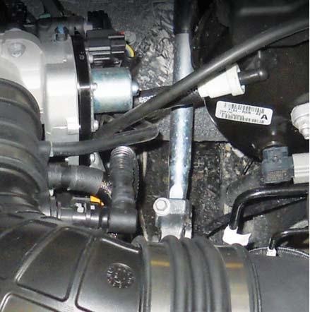
11 SECTION A DISASSEMBLY 9. Cut the heater return hose at the plastic tee fitting at the front passenger side of the engine. Disconnect the heater return hose quick-connect fitting on the front driver side of the engine and remove the cut hose. It is not reused. 12. Disconnect the white quick-connect fitting from the brake booster. 10. Using a suitable tool, cut the clamp from the T-fitting holding the short hose just cut. Remove the hose. 11. Remove the PCV purge line from the intake manifold and passenger side cam cover. This line will not be reused. 13. Disconnect the throttle body electrical connector. (Pull the red locking tab back; press the black release tab to disengage the lock.) Refer to figure shown. 14. Disconnect the VMV (evaporative emission canister purge valve) tube and electrical connector. Remove the VMV tube retainer from the fuel rail and fuel supply line. R1115-P1CAL-AA ROUSH
 fuel injector electrical connectors. 19. Remove the four (4) fuel rail bolts.")
 intake manifold mounting bolts.")


12 SECTION A DISASSEMBLY 1. Throttle Body Electrical Connector 2. VMV Tube 3. VMV Electrical Connector 4. PCV Purge Line 18. Remove and discard the LH and RH fuel rail insulators. Disconnect the eight (8) fuel injector electrical connectors. 19. Remove the four (4) fuel rail bolts. These bolts will be reused. NOTE: It is not necessary to remove the fuel rail from the intake manifold assembly. 20. Remove the remaining six (6) intake manifold mounting bolts. Lift up and move the manifold forward enough to access and remove the retaining pins attaching the wiring harness at the back of the manifold. Remove the intake manifold and fuel rail assembly from the vehicle. This hardware will not be reused. 15. Disconnect the fuel supply line from the fuel rail. Refer to figure shown below. 16. Disconnect the brake booster vacuum hose from the intake manifold. This port is located directly behind the throttle body. 17. Remove the 3/8 engine coolant degas hose from the connection at the engine and place the loose end of the hose to the side for later connection. 21. Carefully disconnect the four (4) harness connectors (circled) and from the rear of the intake manifold. Remove the two (2) pushpins attaching the wiring harness to the manifold; retain the pushpins for reuse at installation. R1115-P1CAL-AA ROUSH
 coil plug electrical connectors and remove the eight (8) coils from the vehicle by removing the bolt securing them to the cam covers. 28.")
 provided with the kit.")

13 SECTION A DISASSEMBLY 22. Clean the intake mounting surfaces and apply tape over the open intake ports to prevent engine contamination. 23. Disconnect the eight (8) coil plug electrical connectors and remove the eight (8) coils from the vehicle by removing the bolt securing them to the cam covers. 28. Remove the four (4) bolts securing the water pump pulley to the engine. 29. Cut the A/C compressor belt and remove the belt from the engine. Then remove the tensioner and the idler; these parts will not be re-used. 24. Remove the factory spark plugs and install the new spark plugs (CYSF 12YP) provided with the kit. Torque to 14 Nm. 25. Re-install the coil on plugs and torque to 6 Nm. Connect the electrical connector to the coil on plugs in eight (8) places. 26. Disconnect both ends of the upper radiator hose and remove from the vehicle. 27. Loosen the four (4) water pump pulley bolts, and then remove the front engine accessory drive (FEAD) belt. Rotate the FEAD tensioner counterclockwise to release the belt tension and remove the belt. R1115-P1CAL-AA ROUSH

14 SECTION B MODIFICATIONS SECTION B MODIFICATIONS The following section will guide you through the required modifications of existing components and build up of the assemblies used to complete the installation. With the exception of the wiring modifications and the A/C compressor clutch assembly R&R, all of this work can be performed away from the vehicle. A/C COMPRESSOR PULLEY REPLACEMENT A/C Clutch Disc and Hub Bolt Removal 1. Using the A/C Clutch Holding Tool, hold the A/C clutch disc and hub. 2. Remove the A/C clutch disc and hub bolt. Compressor Pulley Installation NOTE: The supplemental kit includes the electro magnet as well. Installation of the electro magnet is REQUIRED on 2017 F F-150 can save or discard the electro magnet. 1. Clean the A/C pulley mounting surfaces. NOTE: The A/C compressor pulley is a tight fit on the A/C compressor. It must be correctly aligned during installation. 2. Install the A/C compressor pulley. 3. Install the A/C compressor pulley snap ring with the bevel side out. 4. Place one nominal thickness A/C clutch disc and hub spacer inside the clutch hub spline opening. 3. Remove the A/C clutch disc and hub. 4. Remove the A/C compressor pulley snap ring. Compressor Pulley Removal NOTICE: Do not use air tools. Damage to the air conditioning (A/C) clutch pulley or A/C compressor may result. 1. Install the Compressor Pulley Remover. 2. Remove the A/C compressor pulley. A/C Clutch Disc and Hub Bolt Installation 1. Using the A/C Clutch Holding Tool, hold the A/C clutch disc and hub. 2. Tighten the bolt to 14 Nm. R1115-P1CAL-AA ROUSH


15 SECTION B MODIFICATIONS CRANKSHAFT PULLEY REPLACEMENT NOTE: After crankshaft pulley installation, it will be necessary to relearn the misfire profile correction using RDT. Refer to the RDT-CALIM included with your ROUSHcharger kit. Pulley Removal 1. Loosen the crankshaft pulley bolt and washer. 3. Measure and adjust the clutch air gap at three (3) spaces by removing or adding A/C clutch disc and hub spacers MM ( IN.) 2. Using a 3-Jaw Puller and the crankshaft pulley bolt, remove the crankshaft pulley. Discard the crankshaft pulley bolt. Pulley Installation NOTE: If not secured within 5 minutes, the sealant must be removed and the sealing area cleaned with silicone gasket remover and metal surface prep. Failure to follow this procedure can cause future oil leakage. 1. Apply silicone gasket and sealant to the Woodruff key slot in the crankshaft pulley. R1115-P1CAL-AA ROUSH

 stages: Stage 1: Tighten to 140 Nm. Stage 2: Loosen 360 degrees.")


16 SECTION B MODIFICATIONS 2. Lubricate the crankshaft pulley sealing surface with clean engine oil prior to installation. 4. Using the Strap Wrench, install a new crankshaft pulley bolt and the original washer. Tighten the bolt in four (4) stages: Stage 1: Tighten to 140 Nm. Stage 2: Loosen 360 degrees. Stage 3: Tighten to 100 Nm. Stage 4: Tighten an additional 90 degrees 3. Using a suitable Damper Installation Tool, install the crankshaft pulley. BRAKE BOOSTER HOSE AND ASPIRATOR ASSEMBLY MODIFICATION 1. With the brake booster hose and aspirator assembly removed from the intake manifold, locate the stock clean air tube hose with the quick-connect fitting. Carefully cut the hose at the grey port barb as shown and remove the hose and fitting from the brake aspirator. The removed hose and fitting are not reused. R1115-P1CAL-AA ROUSH


 with the new formed EPDM")
17 SECTION B MODIFICATIONS 2. Carefully cut and remove the stock intake manifold hose from the black port of the brake aspirator. The removed hose is not reused. 4. Shorten the brake booster hose as follows. Carefully cut the two (2) nylon hose sections over the four (4) barbed port ends of the coupling and check valves in the areas shown. Remove and discard the hose sections. 3. Slide the clamp away from the check valve and the factory aspirator-to-throttle body hose. Replace the removed hose (top) with the new formed EPDM aspirator-to-throttle body spacer hose (1115-9D692) (bottom) and install it on the brake aspirator assembly. Use the original clamp to secure the hose to the assembly. R1115-P1CAL-AA ROUSH
 sections of brake aspirator 4x4 hose")

 on the black aspirator port. 2.")


18 SECTION B MODIFICATIONS 5. Replace the removed hose sections with two (2) sections of brake aspirator 4x4 hose (1115-9D693). This shortens the brake booster hose line by approximately 2 inches. 6. Complete the hose assembly by installing the new formed EPDM aspirator-to-clean air tube (1115-9D691) on the grey port of the aspirator. Then, install the new 3/8" cap (CS2575) on the black aspirator port. 2. With the line removed from the vehicle, carefully cut along the opposite end of the hose where the fitting is inserted and remove the quick connect fitting from the hose. VMV HOSE MODIFICATION 1. Locate the fuel vapor hose beside the fuel supply line. At the joint where the tube transitions from steel to plastic, cut the VMV line in a vertical direction and remove the covered plastic portion from the steel line fixed in the vehicle. R1115-P1CAL-AA ROUSH


 and secure using one (1) worm drive clamp (62003). 4.")

19 SECTION B MODIFICATIONS 5. Cut a six-inch piece of the protective convolute tubing from that supplied in the kit and insert it over the quick-connect fitting. Position the tubing so it covers the clamp between the fuel supply line and the VMV line and tape the ends of tubing to keep it in position. 3. Install the quick connect fitting into one end of the new VMV hose (27004) and secure using one (1) worm drive clamp (62003). 4. Place the second worm drive clamp (62003) over the opposite end of the new VMV hose and install onto the steel line. Position the clamp so the screw (drive) side is closest to the cylinder head and tighten the clamp. R1115-P1CAL-AA ROUSH
 bosses located at A and B need to be reduced in height such that they are flush, or 2 mm off of the front cover surface.")
20 SECTION B MODIFICATIONS FRONT COVER MODIFICATION Using a grinder or cut-off wheel, modify the front cover in the areas shown. The two (2) bosses located at A and B need to be reduced in height such that they are flush, or 2 mm off of the front cover surface. The boss located at C needs to be reduced in height and cut in half. Cross-hatched surfaces A and B must be lower than or equal to this rib height (2 mm). A B R1115-P1CAL-AA ROUSH


21 SECTION B MODIFICATIONS REMOVE MATERIAL OFF OF BOSS C UNTIL THE 20 MM HEIGHT IS ACHIEVED 20 MM A/C LINE MODIFICATION Grab the A/C line as shown and pull forward to bend the line slightly to reposition it for more clearance at the front of the engine. NOTE: You should be able to pass a 1/4" drive extension through this area. R1115-P1CAL-AA ROUSH
 connector and harness at the front of")


22 SECTION B MODIFICATIONS TPS/ETC WIRING 1. Locate the throttle position sensor (TPS) connector and harness at the front of the passenger side cylinder head. Use a proper depinning tool to remove the connector from the harness. 3. Populate the new connector such that the yellow with violet wire is in position 1, the blue with green wire is in position 2, the brown wire is in position 3, the blue with orange wire is in position 4, the yellow wire is in position 5 and the green with violet wire is in position 6. Install the red plastic lock into the connector to secure the wires in place. 2. Depress the locking tab and separate the empty female 1 x 6 connector from the new TPS/ETC extension harness (131114A595). It will be used in the next step. R1115-P1CAL-AA ROUSH


.")
23 SECTION B MODIFICATIONS 4. Connect the TPS/ETC extension harness to the newly installed connector. The wire colors on each side of the connector pair should align. Route the harness along the main wiring harness to the rear of the driver side cam cover. Use tape or zip ties to secure the extension harness to the main harness. CANISTER PURGE VALVE WIRING 1. Locate the canister purge valve electrical connector at the front of the passenger side cylinder head. Remove and discard the 90-degree wire retainer. Use a proper de-pinning tool to remove the connector from the harness. Discard the retainer. 2. Depress the locking tab and separate the empty female 1 x 2 connector from the canister purge valve extension harness (13119G866). This connector replaces the connector removed in the previous step. Carefully pull the white locking tab forward to allow wires to be installed into the connector. Populate the new connector such that the white with brown wire is in position 1 and the green wire is in position 2. Depress the white locking tab to secure the wires. R1115-P1CAL-AA ROUSH
 over the hole in the front corner of the battery box as shown. 3.")

 onto the J-clip. Use the one (1) M6 x 1.")

24 SECTION B MODIFICATIONS INTERCOOLER PUMP WIRING 1. Install the M6 J-clip found in Hardware Kit E (1115-TVSHKE) over the hole in the front corner of the battery box as shown. 3. Connect the canister purge valve extension harness to the newly installed connector. The wire colors on each side of the connector pair should align. Route the harness along the main wiring harness to the rear of the driver side cam cover. Use tape or zip ties to secure the extension harness to the main harness. 2. Install the relay and fuse from the intercooler pump wiring harness (1315-8W501) onto the J-clip. Use the one (1) M6 x 1.0 x 20 bolt (W S437) from the Hardware Kit E (1115-TVSHKE) to secure the relay and fuse to the J-clip. Torque the bolt to 5 Nm. 3. Route the black ground wire from the I/C pump harness along the chassis and up the radiator support to the battery negative cable terminal. Remove the ground stud nut from the cable terminal and install I/C pump black ground wire eyelet. Reinstall the nut to secure the factory ground and I/C grounding eyelet to the cable terminal; torque the nut to 10 Nm. Install a zip tie to secure the harness to the battery cable. R1115-P1CAL-AA ROUSH
 electrical connectors along the factory engine harness to the rear of the")

 at the rear of the passenger side cylinder head. 2.")
 to the positive terminal of the")
25 SECTION B MODIFICATIONS 5. Route the single wire with the two (2) electrical connectors along the factory engine harness to the rear of the driver side cylinder head. Connect these two (2) connectors inline with the driver side radio capacitor. The single connector will be routed to the intercooler pump in Section D of this manual. AIR CHARGE TEMPERATURE (ACT) WIRING 1. Locate the IMRC sensor connector (light grey) at the rear of the passenger side cylinder head. 2. Connect the IMRC sensor connector into the ACT wiring harness ( A690). 4. Route the red wire (part of the intercooler pump wiring harness installed above) to the positive terminal of the battery cable. Remove the nut from the positive terminal and install the red wire eyelet. Reinstall the nut onto the terminal and torque to 10 Nm. 3. Route the extension wiring harness across the engine to the passenger side cylinder head. R1115-P1CAL-AA ROUSH


 bolts which retain the knock sensors to the engine block and rotate the RH and LH knock sensor toward the RH and LH cylinder")

26 SECTION B MODIFICATIONS 4. Wrap electrical tape around the two (2) blue CMCV connectors at the rear of the cylinder head as shown. 3. Route the extension wiring harness along the back of the driver side cylinder head. CMCV connectors taped up SUPERCHARGER INLET PRESSURE (SIP) WIRING 1. Locate the manifold pressure sensor connector at the rear of the passenger side cylinder head. 2. Connect the SIP extension harness (1115-9D930) to the manifold pressure sensor connector. KNOCK SENSOR ORIENTATION ADJUSTMENT 1. Loosen the two (2) bolts which retain the knock sensors to the engine block and rotate the RH and LH knock sensor toward the RH and LH cylinder heads respectively. In order to do so, first remove the 90-degree plastic wiring retainer clipped to the connector and taped to the wiring convolute. Torque the knock sensor bolts to 25 Nm. 3. Route the extension wiring harness to the driver side cylinder head. T-MAP WIRING 1. Locate the IMRC sensor connector (light grey) at the rear of the driver side cylinder head. 2. Connect the IMRC sensor connector into the T-MAP jumper harness (1115-9A588). R1115-P1CAL-AA ROUSH

 on the airbox flange starting at the position shown and secure it with the supplied clamp. Torque the clamp to 3-5 Nm. 2.")

 as shown. 2. Install the 5 8\" PCV fresh air fitting (1311-9N285) and grommet (1150-5/8GRMT) on the clean air tube. 3.")
27 SECTION C SUBASSEMBLY SECTION C SUBASSEMBLY AIR BOX ASSEMBLY 1. With the stock dirty air duct and airbox tray assembly removed from the vehicle, remove the bolt securing the duct in place on the airbox tray. Separate the tube from the airbox; the airbox tray will not be reused. 5. Install the airbox seal (1115-9B624) on the airbox flange starting at the position shown and secure it with the supplied clamp. Torque the clamp to 3-5 Nm. 2. Transfer and assemble the stock dirty air duct to the new airbox tray (1115-9A612). Install the factory bolt to secure the duct in place. Torque the bolt to 3 Nm. CLEAN AIR TUBE ASSEMBLY 1. Using two (2) hose clamps (R ), install the cuff, T-body-to-CAT (1115SC-9B662) and the coupler, MAF-to-CAT (1115SC-9B661) on the respective ends of the clean air tube (1115SC- 9B660) as shown. 2. Install the 5 8" PCV fresh air fitting (1311-9N285) and grommet (1150-5/8GRMT) on the clean air tube. 3. Install the bypass vacuum fitting ( S) and 3/8" x 3/8" straight connector (P2233A) in the respective ports on the T-body-to-CAT cuff. 3. Install the air filter ( R-AA) on the MAF tube ( B579) and secure it with the supplied clamp. Torque the clamp to 3 Nm. 4. Insert the MAF tube and filter into the airbox tray and secure in place with two (2) M8 x 1.25 x 25 bolts (W S437). Torque the bolts to 10 Nm. R1115-P1CAL-AA ROUSH
 (1115-8K229) on your work surface with the")
 supplied in Hardware Kit")


28 SECTION C SUBASSEMBLY INTERCOOLER LOW TEMPERATURE RADIATOR (LTR) 1. Position the low temp radiator (LTR) (1115-8K229) on your work surface with the inlet and outlet ports facing down as shown. 2. Apply foam tape cut from the bulk tape (1115-8K229FOAM) supplied in Hardware Kit F (1115-TVSHKF) to the top and two (2) sides of the LTR. 3. Remove the protective backing from the foam tape. Place the LTR air deflector (1115-5K235) in position over the LTR using care to align the mounting holes. Install the four (4) M6 x 20 bolts (W S437) to attach the deflector to the LTR. Torque the bolts to 10 Nm. R1115-P1CAL-AA ROUSH
 and a steel grommet insert")
 LTR mounting brackets, lower LH (1115-8K243) and lower RH")
. 5.")
 M8 x 1.")

29 SECTION C SUBASSEMBLY 4. Insert a grommet (R ) and a steel grommet insert (R ) into the vehicle frame mounting holes of the two (2) LTR mounting brackets, lower LH (1115-8K243) and lower RH (1115-8K242) and the LTR mounting spanner bracket (1115-8K241). These can be found in Hardware Kit F (1115-TVSHKF). 5. Position the two (2) LTR lower mounting brackets into place on the LTR. Loosely install one (1) M8 x 1.25 x 20 bolt (90386A108) from Hardware Kit F through the non-grommet/insert bracket hole of each bracket and secure to the threaded boss on the LTR (two [2] places). R1115-P1CAL-AA ROUSH
 to the bubbler fitting (3/8\" barb) on the bottom of the fuel")
 attaches to the two (2) threaded bosses located at the upper end the LTR.")

 will be installed on the LTR spanner bracket after the bracket and the LTR have")
30 SECTION C SUBASSEMBLY INTAKE MANIFOLD BUILD UP 1. Remove the fuel charging assembly (13119H487) from the packaging. 2. Attach the rubber hose from the PCV purge hose (13116K817) to the bubbler fitting (3/8" barb) on the bottom of the fuel charging assembly and secure it with the supplied clamp. 6. The LTR spanner bracket (1115-8K241) attaches to the two (2) threaded bosses located at the upper end the LTR. Do NOT attach the bracket at this time. The spanner bracket must be installed on the vehicle before the LTR assembly is attached. This will be done later in SECTION D INSTALLATION. NOTE: The intercooler pump (F8YH-8501) will be installed on the LTR spanner bracket after the bracket and the LTR have been installed on the vehicle. 3. Install the T-MAP sensor (BV6Z-9F479) on the lower intake manifold housing and secure with an M6 x 1.0 x 16 bolt (W S307) found in Hardware Kit B (1115-TVSHKB). Torque bolt to 10 Nm. R1115-P1CAL-AA ROUSH


 and secure using the two")


31 SECTION C SUBASSEMBLY THROTTLE BODY SPACER ASSEMBLY 1. Remove the evaporative emission canister purge valve from the stock intake manifold. 4. Remove the T-MAP sensor from the stock intake manifold. 5. Install the T-MAP sensor on the throttle body spacer and secure with an M6 x 1.0 x 16 bolt (W S307) found in Hardware Kit B (1115-TVSHKB). Torque bolt to 10 Nm. 2. Install the valve into the new throttle body spacer (1115-9A589) and secure using the two (2) M6 x 31 bolts (R ) found in Hardware Kit B (1115-TVSHKB). Torque bolts to 10 Nm. 3. Connect the supercharger boost bypass actuator hose (short 4" hose R ) to the straight fitting on throttle body spacer. 6. Connect the modified brake aspirator assembly to the 90-degree elbow on the throttle body. This will be connected to the brake booster once the throttle spacer is installed. R1115-P1CAL-AA ROUSH
.")
32 SECTION C SUBASSEMBLY FUEL RAIL ASSEMBLY 1. Carefully install the eight (8) new anti-rotation fuel injector clips (13119C995) onto the fuel injectors (13119F593K) provided. 2. Apply assembly lubricant to the injector O-rings and install the injectors into the new fuel rail (13119F792). NOTE: Verify that the anti-rotation clips are properly aligned and fully engaged into the fuel rail injector cups. R1115-P1CAL-AA ROUSH

 M6 x 1.0 x 40 mm bolts (R18020004) found in Hardware Kit B (1115-TVSHKB). Tighten the fasteners in two stages with the sequence shown.")

33 SECTION D INSTALLATION SECTION D INSTALLATION The following section will guide you through the final installation of the kit into the vehicle. If you need to stop during any part of the installation, make sure you cover any open ports in the cylinder heads or intake manifold to prevent foreign material from contaminating your engine. INTAKE MANIFOLD AND SUPERCHARGER INSTALLATION 1. Remove the tape from the cylinder heads and clean the cylinder head-to-intake manifold mating surfaces. 2. Install the intake manifold using six (6) M6 x 1.0 x 40 mm bolts (R ) found in Hardware Kit B (1115-TVSHKB). Tighten the fasteners in two stages with the sequence shown. Stage 1; torque bolts to 10 Nm. Stage 2; tighten bolts an additional 45 degrees. Reinstall the engine wiring harness retention clips at the rear of the intake manifold. 3. Lubricate the fuel injector O-rings with assembly lubricant. Install the fuel rail and injectors into the intake manifold using the take-off bolts. Be sure each injector is properly seated into the intake manifold. Tighten the fasteners in two stages with the sequence shown. Stage 1; torque bolts to 10 Nm. Stage 2; tighten bolts an additional 45 degrees. 4. Connect the eight (8) fuel injector electrical connectors. 5. Connect the IMRC-MAP wiring harness to the T-MAP sensor installed on the lower intake manifold housing. 6. Connect the ACT wiring harness to the ACT sensor on the passenger side intake manifold. 7. Remove the supercharger assembly (1311H- 6F066) from the protective packaging and place on a workbench or solid, flat surface. Use extreme caution as the bypass actuator housing is fragile. Remove the protective shipping covers. 8. Install the 80 mm supercharger pulley (1313-6K80) onto the hub of the supercharger using the six (6) M6 x 1.0 x 16 bolts (W ) found in Hardware Kit B (1115-TVSHKB). Apply a small amount of blue thread locking compound to the bolts, and torque to 10 Nm. R1115-P1CAL-AA ROUSH

 between the throttle body spacer assembly and the supercharger and mount the spacer using four (4) M6 x 31 bolts (R18020009-00).")


34 SECTION D INSTALLATION 9. Connect the supercharger bypass reference vacuum line (23.5" length of hose R ) to the bottom fitting on the supercharger bypass actuator. Route this underneath the VMV and fuel line. 12. Connect the boost bypass hose from the throttle body spacer to the top port of the supercharger bypass actuator. 10. Insert one (1) of the M8 x 55 fasteners (N S437) found in Hardware Kit B (1115-TVSHKB) into the mounting hole directly below the supercharger inlet. 11. Install the throttle body spacer-to-supercharger gasket (R ) between the throttle body spacer assembly and the supercharger and mount the spacer using four (4) M6 x 31 bolts (R ). These parts can be found in Hardware Kit B (1115-TVSHKB). Torque the fasteners to 10 Nm. 13. With the help of an assistant, carefully place the supercharger and throttle spacer on top of the intake manifold, sliding it underneath the cowl into position. Ensure that the supercharger is fully seated on the intake mounting dowels. NOTE: Make sure the bolt mounted below the throttle body spacers does not catch on anything as you slide the supercharger into position. 14. Install the remaining nine (9) M8 x 55 fasteners (N S437) provided in Hardware Kit B (1115-TVSHKB) into the mounting holes. Torque fasteners in three (3) stages: Stage 1: Tighten fasteners to 10 Nm in the sequence shown. Stage 2: Tighten fasteners to 20 Nm in the sequence shown. Stage 3: Tighten fasteners to 30 Nm in the sequence shown. Access bolt hole number 10 by reaching behind the supercharger from the passenger side of the vehicle. R1115-P1CAL-AA ROUSH


35 SECTION D INSTALLATION 15. Connect the short hose quick connect to the 90-degree fitting on the brake booster. NOTE: It is recommended that some form of abrasionresistant sleeve or convoluting be installed on the brake aspirator lines to prevent chaffing of components. Use care in routing the brake booster hose to avoid crushing the fuel line. 18. Connect the new evaporative emission canister purge valve hose quick-connect fitting to the relocated purge valve on the throttle body spacer. 16. Connect the evaporative emission canister purge valve electrical connector. 17. Connect the new SIP extension harness (1115-9D930) to the TMAP sensor on the throttle body spacer. 19. Connect the fuel inlet line to the fuel rail. Secure the lock into position. R1115-P1CAL-AA ROUSH
 to the PCV valve on the passenger side cam cover")
 in the throttle body spacer.")
 to secure the throttle body assembly (R07060150-13) to")
36 SECTION D INSTALLATION 20. Connect the PCV purge line (13116K817) to the PCV valve on the passenger side cam cover and the port on the supercharger. 21. Install the throttle body gasket (R ) in the throttle body spacer. Use four (4) M6 x 1.0 x 31 mm bolts (R ) to secure the throttle body assembly (R ) to the spacer. Torque bolts to 10 Nm. These can be found in Hardware Kit B (1115-TVSHKB). 22. Connect the TPS and ETC throttle body electrical connectors. R1115-P1CAL-AA ROUSH
 bolts and one (1) stud from the front cover as shown. 2. Remove and discard the 10 mm water pump fastener shown below. 4.")
 found in Hardware Kit C (1315-TVSHKC). Torque bolts to 25 Nm. 3. Install the upper FEAD bracket (1314-8B653U) using one (1) M8 x 1.")
 onto the front cover using two (2) M8 x 1.")
37 SECTION D INSTALLATION FEAD ASSEMBLY NOTE: If installing on F-150, install the components included in the optional supplemental FEAD kit before proceeding. 1. Remove the four (4) bolts and one (1) stud from the front cover as shown. 2. Remove and discard the 10 mm water pump fastener shown below. 4. Install two (2) idler pulleys (953045) onto the machined posts of the upper FEAD bracket. Secure the pulleys using two (2) M8 x 1.25 x 28 mm idler bolts (R ) found in Hardware Kit C (1315-TVSHKC). Torque bolts to 25 Nm. 3. Install the upper FEAD bracket (1314-8B653U) using one (1) M8 x 1.25 x 57 bolt that was removed in the previous step, three (3) M8 x 1.25 x 60 bolts ( ) and two (2) M8 x 1.25 x 84 bolts (W S437) from Hardware Kit C (1315-TVSHKC). Torque bolts to Nm. 5. Loosely install the FEAD tensioner bracket assembly (13118B603) onto the front cover using two (2) M8 x 1.25 x 120 mm bolts (N S437) found in Hardware Kit C (1315-TVSHKC), leaving at least a 10 mm gap between the two (2) new FEAD brackets. R1115-P1CAL-AA ROUSH

 M8 x 1.")
 tensioner bracket bolts to 20-30 Nm. 9.")
38 SECTION D INSTALLATION 6. Route the FEAD belt (6K ). Do not route the belt onto the supercharger pulley. 8. Using a 17 mm socket, rotate the new tensioner clockwise to install the belt on to the supercharger pulley. Inspect each pulley to ensure the belt is properly seated. 7. Install one (1) M8 x 1.25 x 41 mm (W S437) bolt found in Hardware Kit C (1315-TVSHKC), to fasten the tensioner bracket to the upper FEAD bracket. Torque all three (3) tensioner bracket bolts to Nm. 9. Re-install the coolant pump pulley using the four (4) take-off bolts. Torque bolts to Nm. R1115-P1CAL-AA ROUSH


 in position on the fan shroud with the RH mounting hole under the overflow tank and the left hole over the new J-clip.")

39 SECTION D INSTALLATION 10. Re-install the stock FEAD belt by rotating the tensioner counterclockwise and routing the belt as per the stock Ford belt routing. 11. Using a 1/4-inch drive extension as a feeler gauge, make sure it fits between the tensioner bracket and the air conditioning line. INTERCOOLER RESERVOIR MOUNTING 1. Remove the bolt attaching the radiator overflow tank to the fan shroud at the left (driver) side. Set the bolt aside; this bolt location will be used for the degas bottle mounting bracket attachment. 3. Install a M6 J-clip (N S439) supplied in Hardware Kit E (1115-TVSHKE) over the drilled hole. 4. Place the mounting bracket (1115-6B634) in position on the fan shroud with the RH mounting hole under the overflow tank and the left hole over the new J-clip. Install the original overflow tank bolt in the RH mounting hole and an M6 x 1.0 x 20 bolt to secure the bracket in the lower LH J-clip. Torque to 10 Nm. 2. Using the degas bottle-to-fan shroud mounting bracket (1115-6B634) as a template, mark and drill a new mounting hole in the fan shroud. 5. Install the degas bottle (R ) over the two (2) studs on the mounting bracket. Install two (2) M6 nuts (W S437) found in Hardware Kit E (1115-TVSHKE), over the studs and torque to 10 Nm. R1115-P1CAL-AA ROUSH


 M8 x 1.")
 in position between the spanner bracket at the top and the bumper beam. Install two (2) M8 x 1.")
40 SECTION D INSTALLATION 2. Remove the two (2) OEM bolts at the base of the bumper beam inboard of the LH and RH frame rails. These holes will be the attachment point for the lower LTR mounting brackets. The OEM bolts are not reused. INTERCOOLER RADIATOR ASSEMBLY MOUNTING 1. Install the LTR mounting spanner bracket (1115-8K241) on the vehicle between the LH and RH frames rails as follows: Locate the open hole in the top of the LH frame near the front and the corresponding open hole in the RH frame rail. Insert an M8 x 1.25 J-clip (W S439) supplied in Hardware Kit F (1115-TVSHKF) through the opening in each frame rail and over the mounting hole. Place the spanner bracket in position on top of the frame rails with the flange to the rear and facing down. With the mounting holes aligned, install two (2) M8 x 1.25 x 29 bolts (W S437) to attach the spanner bracket to the frame rails. Torque to 25 Nm. 3. Place the LTR assembly (1115-8K229) in position between the spanner bracket at the top and the bumper beam. Install two (2) M8 x 1.25 x 20 bolts (90386A108) supplied in Hardware Kit F (1115-TVSHKF) to attach the LTR to the spanner bar. Torque the bolts to 25 Nm. 4. Align the lower LTR brackets with the open holes in the support panel and install the longer M8 x 1.25 x 33 bolts (N S437) supplied in Hardware Kit F (1115-TVSHKF) to attach the LTR brackets to the bumper beam. Torque the bolts to 25 Nm. R1115-P1CAL-AA ROUSH
 in position on")


41 SECTION D INSTALLATION INTERCOOLER PUMP MOUNTING 1. Place the intercooler pump mounting bracket (R G) in position on the intercooler pump (F8YH-8501) as shown and hand tighten the clamp bolt. Do not fully tighten the bolt at this time to allow for proper alignment of the inlet and outlet ports during installation in the vehicle. 2. Install the pump and bracket assembly on the LTR spanner bracket using two (2) M8 x 1.25 x 29 bolts (W S437). Position the pump so that the inlet tube is facing the LTR outlet tube. Torque the bolts to 25 Nm. R1115-P1CAL-AA ROUSH
 3. LTR outlet hose (1115-8D030) 4. Intercooler pump-to-ltr hose (1115-8K236) NOTE: Route all intercooler hoses very carefully.")
 from the intercooler down along the left radiator support and through the opening between the frame and radiator.")
42 SECTION D INSTALLATION COOLANT HOSES Intercooler Hose Circuit Following are the four (4) 3/4" hoses that make up the intercooler circuit. 1. Intercooler reservoir inlet hose (1115-8D031) 2. Intercooler pump inlet hose ( D029) 3. LTR outlet hose (1115-8D030) 4. Intercooler pump-to-ltr hose (1115-8K236) NOTE: Route all intercooler hoses very carefully. It is critical for intercooler performance that these hoses are not kinked once installed into the vehicle. Starting at the top of the engine, install the hoses as follows. 1. Route the LTR outlet hose (1111-8D030) from the intercooler down along the left radiator support and through the opening between the frame and radiator. Connect the hose to the lower port on the intercooler using one (1) 3/4" constant tension clamp (CT19x12-BO). This can be found in Hardware Kit D (1115-TVSHKD). 2. Route the intercooler pump inlet hose (1115-8D029) from the degas bottle outlet port (bottom port) to the inlet port of the intercooler pump by routing the hose along the radiator support at the left front of the engine. Route the hose through the opening between the frame rail and the radiator support. Connect the hose to the degas bottle using one (1) 3/4" constant tension clamp (CT19x12-BO). 3. Install the intercooler reservoir hose (1111-8D031) between the intercooler outlet port and top port on the degas bottle (facing the cowl). Secure the hose to the inlet of the degas bottle using one (1) 3/4 constant tension clamp (CT19x12-BO). 4. Connect the intercooler pump inlet hose (1115-8D029) from the degas bottle outlet port to the inlet port on the pump using one (1) 3/4" constant tension clamp (CT19x12-BO) at each end. 5. Install one (1) 3/4" constant tension clamp (CT19x12-BO) onto each end of the intercooler pump-to-ltr hose (1115-8K236). Install the hose onto the pump outlet and onto the LTR inlet; position the clamps to secure the hose. R1115-P1CAL-AA ROUSH
 from the")
. 6.")

 underneath the drive snout of")

43 SECTION D INSTALLATION 7. On the passenger side of the LTR, connect the LTR outlet hose (1115-8D030) from the intercooler lower port to the outlet port on the LTR using one (1) 3/4" constant tension clamp (CT19x12-BO). 6. Connect the intercooler pump electrical jumper harness (1315-8W501) to the pump. Then, using a zip tie, secure the harness to the transmission cooler line at the center of the front crossmember. Heater Hose 1. Route the new heater inlet hose assembly ( K579) underneath the drive snout of the supercharger and connect the 90-degree quickconnect fitting to the heater return tube. 2. Remove the turret bolt on the upper passenger side of the engine, and install the P-clip that was in the heater hose kit. Wrap the clip around the heater inlet hose as shown and re-install the turret bolt. Torque to 10 Nm. R1115-P1CAL-AA ROUSH


 heater hoses together and")


44 SECTION D INSTALLATION 4. Reinstall the upper radiator hose and connect to both the engine and radiator. 3. Connect the other end of the heater inlet hose assembly ( K579) to the heater hose T- fitting at the passenger side of the engine and secure with a clamp (8863T78). Route the two (2) heater hoses together and re-connect the plastic hose connector that will hold them together. 5. Reinstall the factory 3/8" engine degas bottle hose between the new degas bottle and the fitting on the driver side cylinder head. Secure with the constant tension clamp. R1115-P1CAL-AA ROUSH


45 SECTION D INSTALLATION AIR INDUCTION SYSTEM 1. If not already done, reinstall the OEM mounting bolt and rubber isolator. Place the new ROUSH air box and OEM dirty air duct assembly in position on the vehicle. Align and slide the edge slot of the air box into the rubber isolator and secure the assembly in place with the two (2) original pushpins at the front of the dirty air duct. FINAL ASSEMBLY 1. Cut a 25 cm piece of heater hose from the discarded piece. Carefully cut the piece open as shown. 2. Install the new clean air tube assembly (1115SC- 9B660) into position between the throttle body and the MAF tube. Torque the clamps on each end to 3 Nm. 2. Use the piece of hose to cover the PCV line on the passenger side coil cover. Use 2 (two) zip ties to attach it at each end. 3. Connect the PCV fresh air inlet line from the cam cover and to the quick-connect fitting on the clean air tube. Connect the bypass vacuum line to the small upper fitting and the brake aspirator hose to the lower fitting in the cuff at the throttle body. 3. Fill the engine cooling system (using a proper coolant mixture) to the marked level on the radiator degas bottle. Make sure the radiator petcock is closed tightly. R1115-P1CAL-AA ROUSH
 and tighten when full. IMPORTANT: Both coolant systems can trap a large amount of air.")


46 SECTION D INSTALLATION 4. Using the same coolant mixture, fill the intercooler system through the degas bottle. The coolant should be approximately one inch below the top of the cap. Install the degas bottle cap (9C3Z- 8101) and tighten when full. IMPORTANT: Both coolant systems can trap a large amount of air. It is very important to verify that the air is purged and that coolant is flowing properly through both systems. ROUSH recommends vacuum filling both systems to properly evacuate the trapped air. 5. Inspect all underhood wiring harnesses for potential interference issues. Use zip ties to safely position the harness away from any areas of concern. 6. If the PCM was removed and shipped to ROUSH for a ROUSH-performed flash, reinstall it once the PCM is returned from ROUSH. If you are equipped with a SAE J2534 pass-through device, refer to the PCM Flashing section when installation is complete. DO NOT ATTEMPT TO REINSTALL THE PCM AND START THE VEHICLE IF THE PCM IS NOT EQUIPPED WITH A ROUSH CALIBRATION. OPERATING THE ENGINE WITHOUT THE RECALIBRATED PCM WILL RESULT IN ENGINE DAMAGE OR FAILURE AND WILL VOID THE WARRANTY. 7. Re-install the battery into the vehicle and make the terminal connections by connecting the positive (+) cable first then connecting the negative (-) cable. 8. Reconnect the fuel pump control module electrical connector located above the spare tire on the frame. 9. Place the PCM warning sticker above the PCM on the cowl of the vehicle. 10. The belt routing diagram (13116E072) is to be placed on the underside of the hood, on the driver side, opposite of the factory Vehicle Emission Control Information decal. 11. Place the fuel door decal (R ) on the backside of the fuel door. With the supercharger system installed, the vehicle is no longer E85 compatible. If your vehicle has a Flex-Fuel badge, it is recommended that this also be removed at this time. 12. Place the premium unleaded fuel only decal (13109A095) inside the fuel door, below the fuel filler neck. 13. Place the "Premium Fuel" clear decal with white lettering on the instrument cluster bezel, on the flat area below the small center gauges as shown. R1115-P1CAL-AA ROUSH
47 SECTION D INSTALLATION 14. If performing the PCM Flash procedure, proceed to the "PCM Flashing" section. If the PCM was sent to ROUSH for the Optional ROUSH Performed Flash and it has been reinstalled, start the engine and check for unusual noise, dash service lights, and/or unusual operation. If problems are detected, immediately stop the engine or vehicle, diagnose and repair the problem. Congratulations, you can now go enjoy your new ROUSHcharged 5.0L F-150. PCM FLASHING 1. If equipped with a SAE J2534 pass-through device, refer to the RDT-CALIM manual included in the CALKIT for PCM flashing. The RDT-CALIM manual will guide you through the ROUSH Diagnostic Tool (RDT) software installation process and the ROUSH PCM flashing procedure. OPERATING THE ENGINE WITHOUT THE RECALIBRATED PCM WILL RESULT IN ENGINE DAMAGE OR FAILURE AND WILL VOID THE WARRANTY. 2. Once the PCM has been successfully recalibrated, start the engine and check for unusual noises, dash service lights, and unusual operation. If problems are detected, immediately stop the engine or vehicle, diagnose and repair the problem. R1115-P1CAL-AA ROUSH


 10 mm screws that hold in the front grille.")
 pushpins that attach the liner to the")
 on either end that hold the side grille")
48 SECTION E UPPER AND LOWER GRILLE REMOVAL SECTION E UPPER AND LOWER GRILLE REMOVAL REMOVAL PROCEDURE 1. Remove the grille closeout by using a trim tool to take out ten (10) pushpins. Retain the close out and pushpins for reinstallation. 4. Release the clips on the side grille pieces, but DO NOT COMPLETELY REMOVE THEM. 2. Remove the four (4) 10 mm screws that hold in the front grille. Retain the bolts for reinstallation. 5. Use a trim tool to remove three (3) pushpins that attach the liner to the grille. Repeat this on the other side. Retain pushpins for reinstallation. 3. Remove the pushpins (2 total) on either end that hold the side grille pieces. Retain the pushpins for reinstallation. R1115-P1CAL-AA ROUSH

 fasteners for reinstallation. 9.")


49 SECTION E UPPER AND LOWER GRILLE REMOVAL 6. Unplug the wire harnesses on the top center of the grille. 7. Remove the 8 mm screws at the bottom corners of the grille. Retain the two (2) fasteners for reinstallation. 9. Unfasten the lower grille liner by removing the pushpins that are attached to the front bumper. 8. Remove the grille by pulling upward first to disengage the locating pins on the top of the grille. Then pull forward on the center of the grille to remove it. 10. Remove the lower grille by unlatching the clips that hold it onto the bumper. NOTE: Flat-jaw pliers can be used to compress the clips for easier removal. R1115-P1CAL-AA ROUSH


50 SECTION E UPPER AND LOWER GRILLE REMOVAL 11. Modify the stock bumper cover to provide an opening for the radiator, purchase Ford EcoBoost part (FL3Z-17E810-DA) shown below and reverse the removal procedure or purchase Roush bumper cover. R1115-P1CAL-AA ROUSH
Ford F L PHASE 2 ROUSHcharger Kit
 2011-2014 Ford F-150 6.2L PHASE 2 ROUSHcharger Kit P/N: 421432 (1162-P2CAL) EO # D-418-23 Installation Instructions Application: 2011-2014 Ford F-150 with 6.2L 2-Valve Engine w/ Automatic Transmission.
Installation Instructions
 2012-2014 Ford F-150 ROUSH Phase 1 Kit 3.5L V6 Eco-Boost P/N: 421735 (1135-P1CAL) Installation Instructions Before installing your ROUSH Cold Air Kit, please read through the entire installation procedure
M-6066-SGT (Black)/M-6066-SGTP (Polished) SVT Mustang Supercharger Upgrade Kit INSTALLATION INSTRUCTIONS
/M-6066-SGTP (Polished) SVT Mustang Supercharger Upgrade Kit INSTALLATION INSTRUCTIONS") Please contact the Techline for the most current instruction information (800) FORD788.!!! PLEASE READ THE FOLLOWING INSTRUCTIONS CAREFULLY PRIOR TO INSTALLATION!!! OVERVIEW: This kit is designed for use
Please contact the Techline for the most current instruction information (800) FORD788.!!! PLEASE READ THE FOLLOWING INSTRUCTIONS CAREFULLY PRIOR TO INSTALLATION!!! OVERVIEW: This kit is designed for use
LChevrolet Camaro Supercharger Kit
 PART #92000A Important Notes: 2010-2013 6.2LChevrolet Camaro Supercharger Kit The use of fuel additives (ie. octane boosters) is not recommended. There is a possibility that these chemicals can damage
L Mustang Phase 1 ROUSHcharger Kit Installation Instructions P/N: (R1315-P1CAL) EO D (EO not applicable with MY2016)
 EO D (EO not applicable with MY2016)") 2015-2016 5.0L Mustang Phase 1 ROUSHcharger Kit Installation Instructions P/N: 421823 (R1315-P1CAL) EO D-418-25 (EO not applicable with MY2016) 39555 Schoolcraft Rd, Plymouth MI, 48170 800.59.ROUSH 2015
2015-2016 5.0L Mustang Phase 1 ROUSHcharger Kit Installation Instructions P/N: 421823 (R1315-P1CAL) EO D-418-25 (EO not applicable with MY2016) 39555 Schoolcraft Rd, Plymouth MI, 48170 800.59.ROUSH 2015
L Mustang Supercharger Kit
 2015-2017 5.0L Mustang Supercharger Kit Installation Instructions P/N: M-6066-M8627 EO D-418-27 Application: 2015-2017 Ford Mustang GT with 5.0L 4-Valve Engine w/ Manual Transmission Important Notes: Before
2018 F L Cold Air Intake Installation Instructions P/N: ( )
") Installation Instructions P/N: 422088 (111850-9600) 39555 Schoolcraft Rd, Plymouth MI, 48170 800.59.ROUSH 2018 F-150 5.0L Cold Air Intake Installation Instructions P/N: 422088 (111850-9600) Application:
Installation Instructions P/N: 422088 (111850-9600) 39555 Schoolcraft Rd, Plymouth MI, 48170 800.59.ROUSH 2018 F-150 5.0L Cold Air Intake Installation Instructions P/N: 422088 (111850-9600) Application:
F L NA Cold Air Intake Installation Instructions P/N: ( )
") 2015-2017 F-150 3.5L NA Cold Air Intake Installation Instructions P/N: 421982 (111535-9600) 39555 Schoolcraft Rd, Plymouth MI, 48170 800.59.ROUSH 2015-2017 F-150 3.5L NA Cold Air Intake Installation Instructions
2015-2017 F-150 3.5L NA Cold Air Intake Installation Instructions P/N: 421982 (111535-9600) 39555 Schoolcraft Rd, Plymouth MI, 48170 800.59.ROUSH 2015-2017 F-150 3.5L NA Cold Air Intake Installation Instructions
Installation Instructions
 2011+ Mustang GT Supercharger Kit(s) P/Ns: M-6066-MGT525D M-6066-MGT525PD M-6066-MGT624D M-6066-MGT624PD Installation Instructions Application: 2011+ Ford Mustang GT with 5.0L 4-Valve Engines w/ Manual
F L Ecoboost V F L Ecoboost V6 Performance Pac Level 2 Installation Instructions P/N: (1115TT-PWRPK2)
") 2015-2016 F-150 3.5L Ecoboost V6 2015-2017 F-150 2.7L Ecoboost V6 Performance Pac Level 2 Installation Instructions P/N: 422007 (1115TT-PWRPK2) 39555 Schoolcraft Rd, Plymouth MI, 48170 800.59.ROUSH 2015-2016
2015-2016 F-150 3.5L Ecoboost V6 2015-2017 F-150 2.7L Ecoboost V6 Performance Pac Level 2 Installation Instructions P/N: 422007 (1115TT-PWRPK2) 39555 Schoolcraft Rd, Plymouth MI, 48170 800.59.ROUSH 2015-2016
2018 Mustang 5.0L Cold Air Intake Installation Instructions P/N: ( )
") Installation Instructions P/N: 422086 (131850-9600) 39555 Schoolcraft Rd, Plymouth MI, 48170 800.59.ROUSH 2018 Mustang 5.0L Cold Air Intake Installation Instructions P/N: 422086 (131850-9600) Application:
Installation Instructions P/N: 422086 (131850-9600) 39555 Schoolcraft Rd, Plymouth MI, 48170 800.59.ROUSH 2018 Mustang 5.0L Cold Air Intake Installation Instructions P/N: 422086 (131850-9600) Application:
2018 Mustang 5.0L Performance PAC1 Installation Instructions P/N: ( PERFPK1)
") 2018 Mustang 5.0L Performance PAC1 Installation Instructions P/N: 422113 (131850-PERFPK1) 39555 Schoolcraft Rd, Plymouth MI, 48170 800.59.ROUSH 2018 Mustang 5.0L Performance PAC1 Installation Instructions
2018 Mustang 5.0L Performance PAC1 Installation Instructions P/N: 422113 (131850-PERFPK1) 39555 Schoolcraft Rd, Plymouth MI, 48170 800.59.ROUSH 2018 Mustang 5.0L Performance PAC1 Installation Instructions
2015 Mustang Ecoboost Cold Air Intake
 2015 Mustang Ecoboost Cold Air Intake Installation Instructions P/N: 421827 (131523-9A600) Application: 2015 Ford Mustang 2.3L Manual or Automatic Transmission Important Note: Before installing the ROUSH
Mustang 5.0L Cold Air Intake Installation Instructions P/N:
 2015-2017 Mustang 5.0L Cold Air Intake Installation Instructions P/N: 421826 39555 Schoolcraft Rd, Plymouth MI, 48170 800.59.ROUSH 2015-2017 Mustang 5.0L Cold Air Intake Installation Instructions P/N:
Mustang V-6 Level 1 Performance Pack Installation Instructions P/N: ( PWRPK1-AA)
") 2015-2017 Mustang V-6 Level 1 Performance Pack Installation Instructions P/N: 421999 (131537-PWRPK1-AA) 39555 Schoolcraft Rd, Plymouth MI, 48170 800.59.ROUSH 2015-2017 Mustang V-6 Level 1 Performance Pack
2015-2017 Mustang V-6 Level 1 Performance Pack Installation Instructions P/N: 421999 (131537-PWRPK1-AA) 39555 Schoolcraft Rd, Plymouth MI, 48170 800.59.ROUSH 2015-2017 Mustang V-6 Level 1 Performance Pack
M-9603-GTB 85 mm Cold Air Kit w/premium Cal. for 4.6L 3V V8 Mustang INSTALLATION INSTRUCTIONS
 Please contact the Techline for the most current instruction information 800-367-3788.!!! PLEASE READ THE FOLLOWING INSTRUCTIONS CAREFULLY PRIOR TO INSTALLATION!!! OVERVIEW: This kit is designed for use
M-9603-CJ 123 mm Cold Air Kit for 5.4L 4V V8 Cobra Jet Mustang INSTALLATION INSTRUCTIONS
 Please contact the Techline for the most current instruction information 1-800-367-3788.!!! PLEASE READ THE FOLLOWING INSTRUCTIONS CAREFULLY PRIOR TO INSTALLATION!!! OVERVIEW: This kit is designed for
M-9603-SVT mm Cold Air Kit w/premium Calibration INSTALLATION INSTRUCTIONS
 Please visit www.fordracingparts.com for the most current instruction information!!! PLEASE READ ALL OF THE FOLLOWING INSTRUCTIONS CAREFULLY PRIOR TO INSTALLATION. AT ANY TIME YOU DO NOT UNDERSTAND THE
F L and 2.7L Ecoboost V6
 2015-2016 F-150 3.5L and 2.7L Ecoboost V6 Installation Instructions P/N: 421981 (1115TT-9600) Application: 2015-2016 Ford F-150 2.7L Ecoboost V6, 2015-2016 Ford F-150 3.5L Ecoboost V6 Important Note: Before
2018 Mustang Ecoboost Cold Air Intake P/N: ( ) Application: 2018 Ford Mustang 2.3L Manual or Automatic Transmission
 Application: 2018 Ford Mustang 2.3L Manual or Automatic Transmission") 2018 Mustang Ecoboost Cold Air Intake P/N: 422087 (131823-9600) Application: 2018 Ford Mustang 2.3L Manual or Automatic Transmission Installation Instructions Before installing your ROUSH Performance Product(s),
2018 Mustang Ecoboost Cold Air Intake P/N: 422087 (131823-9600) Application: 2018 Ford Mustang 2.3L Manual or Automatic Transmission Installation Instructions Before installing your ROUSH Performance Product(s),
Installation Instructions
 SLP GM/Chevrolet LS3 COIL COVER KIT 2010+ Camaro 5.3L/6.2L 2007+ GMT900 5.3L/6.2L PN: 620038 Installation Instructions Important Notes: Before installing your SLP Coil Cover Kit, please read the installation
M-9603-SVT mm Cold Air Kit w/premium Calibration INSTALLATION INSTRUCTIONS
 Please contact the Tech Line for the most current instruction information (800) 367-3788.!!! PLEASE READ THE FOLLOWING INSTRUCTIONS CAREFULLY PRIOR TO INSTALLATION!!! OVERVIEW: This kit is designed for
2012+ Focus Focus ST ROUSH Cold Air Induction Kit(s)
") 2012+ Focus 2013+ Focus ST ROUSH Cold Air Induction Kit(s) P/N: 421642 (1213NA-9600) 421609 (1213ST-9600) Installation Instructions Before installing your ROUSH Performance Product(s), read through the
2012+ Focus 2013+ Focus ST ROUSH Cold Air Induction Kit(s) P/N: 421642 (1213NA-9600) 421609 (1213ST-9600) Installation Instructions Before installing your ROUSH Performance Product(s), read through the
2015+ Mustang Rear Valance Installation Instructions P/N: (R F953) (R F953BS)
 (R F953BS)") 2015+ Mustang Rear Valance Installation Instructions P/N: 421894 (R1315-17F953) 421919 (R1315-17F953BS) 39555 Schoolcraft Rd, Plymouth MI, 48170 800.59.ROUSH 2015+ Mustang Rear Valance Kit Installation
2015+ Mustang Rear Valance Installation Instructions P/N: 421894 (R1315-17F953) 421919 (R1315-17F953BS) 39555 Schoolcraft Rd, Plymouth MI, 48170 800.59.ROUSH 2015+ Mustang Rear Valance Kit Installation
ROUSH Convertible Stylebar Installation Instructions P/N: (1315-STYLEBAR) Convertible Only
 Convertible Only") Installation Instructions P/N: 421911 (1315-STYLEBAR) Convertible Only 39555 Schoolcraft Rd, Plymouth MI, 48170 800.59.ROUSH Installation Instructions P/N: 421911 (1315-STYLEBAR) Convertible Only Application:
Installation Instructions P/N: 421911 (1315-STYLEBAR) Convertible Only 39555 Schoolcraft Rd, Plymouth MI, 48170 800.59.ROUSH Installation Instructions P/N: 421911 (1315-STYLEBAR) Convertible Only Application:
INSTALLATION GUIDE HOLDEN COLORADO (RG) INTERCOOLER KIT P/N PWI66175K INTERCOOLER P/N PWA64553 ( ) PIPE KIT
 INTERCOOLER KIT P/N PWI66175K INTERCOOLER P/N PWA64553 ( ) PIPE KIT") INSTALLATION GUIDE HOLDEN COLORADO (RG) INTERCOOLER KIT P/N PWI66175K INTERCOOLER P/N PWA64553 (2012-13) PIPE KIT ENGINEERING THE UNFAIR ADVANTAGE Contents CONDITIONAL MANUFACTURERS WARRANTY... 2 Warranty
INSTALLATION GUIDE HOLDEN COLORADO (RG) INTERCOOLER KIT P/N PWI66175K INTERCOOLER P/N PWA64553 (2012-13) PIPE KIT ENGINEERING THE UNFAIR ADVANTAGE Contents CONDITIONAL MANUFACTURERS WARRANTY... 2 Warranty
Mustang V-6 Cold Air Intake P/N: ( A600) Application: Ford Mustang 3.7L Manual or Automatic Transmission
 Application: Ford Mustang 3.7L Manual or Automatic Transmission") 2015-2017 Mustang V-6 Cold Air Intake P/N: 421828 (131537-9A600) Application: 2015-2017 Ford Mustang 3.7L Manual or Automatic Transmission Installation Instructions Before installing your ROUSH Performance
2015-2017 Mustang V-6 Cold Air Intake P/N: 421828 (131537-9A600) Application: 2015-2017 Ford Mustang 3.7L Manual or Automatic Transmission Installation Instructions Before installing your ROUSH Performance
2015+ F-150 Active Exhaust Kit Installation Instructions P/N: (1117-5E292LITE)
") 2015+ F-150 Active Exhaust Kit Installation Instructions P/N: 422104 (1117-5E292LITE) 39555 Schoolcraft Rd, Plymouth MI, 48170 800.59.ROUSH 2015+ Ford F-150 Active Exhaust Kit Installation Instructions
2015+ F-150 Active Exhaust Kit Installation Instructions P/N: 422104 (1117-5E292LITE) 39555 Schoolcraft Rd, Plymouth MI, 48170 800.59.ROUSH 2015+ Ford F-150 Active Exhaust Kit Installation Instructions
Installation Instructions
 2014+ Silverado Sierra 5.3L and 6.2L TVS1900 Supercharger Kit P/N: 620068 (2414-6006) 620072 (241462-6006) Installation Instructions Applications: 2014+ GMC Sierra and Chevrolet Silverado 1500 Trucks with
2015 Mustang Heat Extractors Installation Instructions P/N: (R C920)
") Installation Instructions P/N: 421869 (R1315-16C920) 39555 Schoolcraft Rd, Plymouth MI, 48170 800.59.ROUSH 2015 Mustang Heat Extractors Installation Instructions P/N: 421869 (R1315-16C920) Application:
Installation Instructions P/N: 421869 (R1315-16C920) 39555 Schoolcraft Rd, Plymouth MI, 48170 800.59.ROUSH 2015 Mustang Heat Extractors Installation Instructions P/N: 421869 (R1315-16C920) Application:
2018+ Mustang Lower Grill and Chin Spoiler Kits Installation Instructions P/N: (R K945) P/N: (R F775)
 P/N: (R F775)") 2018+ Mustang Lower Grill and Chin Spoiler Kits Installation Instructions P/N: 422081 (R1318-17K945) P/N: 422082 (R1318-17F775) 39555 Schoolcraft Rd, Plymouth MI, 48170 800.59.ROUSH 2018+ Mustang Lower
2018+ Mustang Lower Grill and Chin Spoiler Kits Installation Instructions P/N: 422081 (R1318-17K945) P/N: 422082 (R1318-17F775) 39555 Schoolcraft Rd, Plymouth MI, 48170 800.59.ROUSH 2018+ Mustang Lower
ROUSH Active IO Exhaust. Installation Instructions P/N: (R LITE) Fastback GT Convertible GT V8
 Fastback GT Convertible GT V8") Installation Instructions P/N: 422128 (R1318-5231LITE) Fastback GT Convertible GT V8 39555 Schoolcraft Rd, Plymouth MI, 48170 800.59.ROUSH ROUSH Active IO Exhaust Installation Instructions P/N: 422128
Installation Instructions P/N: 422128 (R1318-5231LITE) Fastback GT Convertible GT V8 39555 Schoolcraft Rd, Plymouth MI, 48170 800.59.ROUSH ROUSH Active IO Exhaust Installation Instructions P/N: 422128
2015+ Mustang GT V8 X-Pipe Exhaust Kit Installation Instructions P/N: (99-137)
") 2015+ Mustang GT V8 X-Pipe Exhaust Kit Installation Instructions P/N: 422046 (99-137) 39555 Schoolcraft Rd, Plymouth MI, 48170 800.59.ROUSH 2015+ Mustang GT V8 X-Pipe Exhaust Kit Installation Instructions
2015+ Mustang GT V8 X-Pipe Exhaust Kit Installation Instructions P/N: 422046 (99-137) 39555 Schoolcraft Rd, Plymouth MI, 48170 800.59.ROUSH 2015+ Mustang GT V8 X-Pipe Exhaust Kit Installation Instructions
Procharger Stage II Intercooled Supercharger System (11-14 GT)
") Procharger Stage II Intercooled Supercharger System (11-14 GT) Installation Time: Approximately one day. Installed on 2012 Mustang GT 5.0/Manual Required Tools 3/8 Socket Set (Standard and Metric) 1/2
Procharger Stage II Intercooled Supercharger System (11-14 GT) Installation Time: Approximately one day. Installed on 2012 Mustang GT 5.0/Manual Required Tools 3/8 Socket Set (Standard and Metric) 1/2
2015+ Mustang GT V8 X-Pipe/H-Pipe Exhaust Kit Installation Instructions
 2015+ Mustang GT V8 X-Pipe/H-Pipe Exhaust Kit Installation Instructions P/N: 422046 and 422119 39555 Schoolcraft Rd, Plymouth MI, 48170 800.59.ROUSH 2015+ Mustang GT V8 X-Pipe/H-Pipe Exhaust Kit Installation
INSTALLATION GUIDE NISSAN NAVARA INTERCOOLER KIT P/N PWI65094K
 INSTALLATION GUIDE NISSAN NAVARA INTERCOOLER KIT P/N PWI65094K ENGINEERING THE UNFAIR ADVANTAGE Contents CONDITIONAL MANUFACTURERS WARRANTY... 2 WARRANTY VOIDS... 2 WARRANTY DOES NOT COVER... 2 LIMIT OF
ENGINE ASSEMBLY STOCK TO 250 HP
 GM SPORT COMPACT Performance Build Book 25 ENGINE ASSEMBLY STOCK TO 250 HP Fig. 3 The stock ECOTEC engine has proven reliable to 250 hp.(fig. 3) Performance upgrades are available from GM Performance Parts
10-RIB BELT SYSTEM UPGRADE INSTALLATION MANUAL
 10-RIB BELT SYSTEM UPGRADE INSTALLATION MANUAL 2011-2017 AND UP FORD MUSTANG GT 5.0L COYOTE WHIPPLE SUPERCHARGERS 3292 NORTH WEBER AVE FRESNO, CA 93722 TEL 559.442.1261 FAX 559.442.4153 WWW.WHIPPLESUPERCHARGERS.COM
10-rib belt system upgrade Installation Manual
 10-rib belt system upgrade Installation Manual 2011-2017 and up Ford MUSTANG gt 5.0l coyote WHIPPLE SUPERCHARGERS 3292 NORTH WEBER AVE FRESNO, CA 93722 TEL 559.442.1261 FAX 559.442.4153 A color PDF of
2015+ Mustang I-4 Y-Pipe Exhaust Kit Installation Instructions P/N: (1315-5G206)
") 2015+ Mustang I-4 Y-Pipe Exhaust Kit Installation Instructions P/N: 422091 (1315-5G206) 39555 Schoolcraft Rd, Plymouth MI, 48170 800.59.ROUSH 2015+ Mustang I-4 Y-Pipe Exhaust Kit Installation Instructions
2015+ Mustang I-4 Y-Pipe Exhaust Kit Installation Instructions P/N: 422091 (1315-5G206) 39555 Schoolcraft Rd, Plymouth MI, 48170 800.59.ROUSH 2015+ Mustang I-4 Y-Pipe Exhaust Kit Installation Instructions
2018+ Mustang Hood Heat Extractors Installation Instructions P/N: (R C920)
") 2018+ Mustang Hood Heat Extractors Installation Instructions P/N: 422083 (R1318-16C920) 39555 Schoolcraft Rd, Plymouth MI, 48170 800.59.ROUSH 2018+ Mustang Hood Heat Extractors Installation Instructions
2018+ Mustang Hood Heat Extractors Installation Instructions P/N: 422083 (R1318-16C920) 39555 Schoolcraft Rd, Plymouth MI, 48170 800.59.ROUSH 2018+ Mustang Hood Heat Extractors Installation Instructions
2015+ Ford F-150 Off-Road Exhaust Kit
 2015+ Ford F-150 Off-Road Exhaust Kit Installation Instructions P/N: 421985 (1115-5E292ORR) Application: 2015+ Ford F-150 OFF-ROAD USE ONLY Important Note: Before installing the ROUSH Performance Product,
M-9424-M50CJ INTAKE MANIFOLD INSTALLATION INSTRUCTIONS
 Please visit www.fordracingparts.com for the most current instruction information!!! PLEASE READ ALL OF THE FOLLOWING INSTRUCTIONS CAREFULLY PRIOR TO INSTALLATION. AT ANY TIME YOU DO NOT UNDERSTAND THE
3.4L V6 SUPERCHARGER 7 TH INJECTOR KIT
 Part Number: 00602-17620-260 00602-17620-261 00602-17620-263 00602-17620-264 00602-17620-274 00602-17620-275 00602-17620-276 Section I Installation Preparation Kit Contents Item # Quantity Reqd. Description
Engine. Special Tool(s) Compressor, Piston Ring 303-D032 (D81L-6002-C) or equivalent. Compressor, Valve Spring (T93P-6565-AR)
 Compressor, Piston Ring 303-D032 (D81L-6002-C) or equivalent. Compressor, Valve Spring (T93P-6565-AR)") SECTION 303-01C: Engine 5.4L (4V) 2009 Mustang Workshop Manual ASSEMBLY Procedure revision date: 12/12/2008 Engine Special Tool(s) Compressor, Piston Ring 303-D032 (D81L-6002-C) or equivalent Compressor,
SECTION 303-01C: Engine 5.4L (4V) 2009 Mustang Workshop Manual ASSEMBLY Procedure revision date: 12/12/2008 Engine Special Tool(s) Compressor, Piston Ring 303-D032 (D81L-6002-C) or equivalent Compressor,
1999 E-Series Workshop Manual
 http://www.fordservicecontent.com/pubs/content/~wsxm/~mus~len/21/sxm31c16.h... Page 1 of 3 SECTION 303-01C: Engine 6.8L 1999 E-Series Workshop Manual IN-VEHICLE REPAIR Procedure revision date: 06/30/1998
Front Fascia Kit Installation Instructions P/N:
 Installation Instructions P/N: 421843 421844 421845 421846 421847 421848 421849 421850 421851 421852 421853 39555 Schoolcraft Rd, Plymouth MI, 48170 800.59.ROUSH 2015-2017 Front Fascia Kit Installation
2015+ Mustang Trunk Toolkit Installation Instructions P/N: (R1315-TOOLKIT)
") Installation Instructions P/N: 421910 (R1315-TOOLKIT) 39555 Schoolcraft Rd, Plymouth MI, 48170 800.59.ROUSH 2015+ Mustang Trunk Toolkit Installation Instructions P/N: 421910 (R1315-TOOLKIT) Important Note:
Installation Instructions P/N: 421910 (R1315-TOOLKIT) 39555 Schoolcraft Rd, Plymouth MI, 48170 800.59.ROUSH 2015+ Mustang Trunk Toolkit Installation Instructions P/N: 421910 (R1315-TOOLKIT) Important Note:
2014 GM Truck Level 1 Performance Pack
 2014 GM Truck Level 1 Performance Pack Installation Instructions P/N: 2414-PRFPC1-AA Application: 2014+ Chevy Silverado and GMC Sierra 5.3L and 6.2L Important Note: Before installing your Blackwing cold
Installation Instructions for: TOYOTA 4.5L SUPERCHARGER SYSTEM
 Installation Instructions for: TOYOTA 4.5L SUPERCHARGER SYSTEM 1995-1997 Land Cruiser * PREMIUM FUEL REQUIRED * Magnuson Products LLC 1990 Knoll Drive, Bldg A, Ventura, CA 93003 (805) 642-8833 phone *
Weistec M113K Supercharger System Installation Guide
 Weistec M113K Supercharger System Installation Guide WARNING! DO NOT HAVE YOUR ECU REPROGRAMMED ANYWHERE BUT AT WEISTEC FOR THIS SUPERCHARGER. THE AMG 55 USES AN ELECTRONIC THROTTLE CONTROL (ETC), WHICH
Intake Manifold Removal
 PLEASE READ ALL OF THE FOLLOWING INSTRUCTIONS CAREFULLY PRIOR TO INSTALLATION. AT ANY TIME YOU DO NOT UNDERSTAND THE INSTRUCTIONS Parts included: -GT350 Intake manifold M-944-M5 -GT350 Air bucket w/filter.
2015+ Mustang Shift Ball Installation Instructions P/N: (R BLK) P/N: (R WHT)
 P/N: (R WHT)") 2015+ Mustang Shift Ball Installation Instructions P/N: 421906 (R1315-7213 BLK) P/N: 421907 (R1315-7213 WHT) 39555 Schoolcraft Rd, Plymouth MI, 48170 800.59.ROUSH 2015+ Mustang Shift Ball Installation
2015+ Mustang Shift Ball Installation Instructions P/N: 421906 (R1315-7213 BLK) P/N: 421907 (R1315-7213 WHT) 39555 Schoolcraft Rd, Plymouth MI, 48170 800.59.ROUSH 2015+ Mustang Shift Ball Installation
2015+ Mustang Windshield Banner Installation Instructions P/N: (R )
") Installation Instructions P/N: 421903 (R1315-03088) 39555 Schoolcraft Rd, Plymouth MI, 48170 800.59.ROUSH 2015+ Mustang Windshield Banner Installation Instructions P/N: 421903 (R1315-03088) Application:
Installation Instructions P/N: 421903 (R1315-03088) 39555 Schoolcraft Rd, Plymouth MI, 48170 800.59.ROUSH 2015+ Mustang Windshield Banner Installation Instructions P/N: 421903 (R1315-03088) Application:
Mustang Hood Scoop
 Installation Instructions P/N: 421858 421859 421860 421861 421862 421863 421864 421865 421866 421867 421868 422055 422056 422057 39555 Schoolcraft Rd, Plymouth MI, 48170 800.59.ROUSH 2015-2017 Mustang
BLACKBIRD INSTALLATION SUPPLEMENT
 BLACKBIRD INSTALLATION SUPPLEMENT FOR 2003-7 FORD 6.0 LITER DIESEL SINGLE ALTERNATOR F-350, F-450, F-550, EXCURSION VERSION 7-07 Parts Description Blackbird Wiring Manual Installation Supplement 6.0 Liter
2015+ Ford F-150 Windshield Banner Kit Installation Instructions P/N: (R )
") 2015+ Ford F-150 Windshield Banner Kit Installation Instructions P/N: 422016 (R1115-03088) 39555 Schoolcraft Rd, Plymouth MI, 48170 800.59.ROUSH 2015+ F-150 Windshield Banner Installation Instructions
2015+ Ford F-150 Windshield Banner Kit Installation Instructions P/N: 422016 (R1115-03088) 39555 Schoolcraft Rd, Plymouth MI, 48170 800.59.ROUSH 2015+ F-150 Windshield Banner Installation Instructions
2015+ Mustang LoudMouth I and LoudMouth II Exhaust Kits
 2015+ Mustang LoudMouth I and Installation Instructions P/N: 620054, 620055, 620061, 620062 (S1315-5231LM1, S1315-5231LM2, S1315S1-5231LM1, S1315S1-5231LM2) *LoudMouth II shown. BY 39555 Schoolcraft Rd,
FREE $15 Gift Card for every $100 spent on Ship To Home orders. Find Out How
 1 of 29 10/12/2011 5:05 PM FREE $15 Gift Card for every $100 spent on Ship To Home orders. Find Out How Ford Ranger/Explorer/Mountaineer 1991-1999 Intake Manifold REMOVAL & INSTALLATION Print The engines
Edelbrock E-Force Supercharger Part #1538: Dodge 1500 Truck 5.7L V8 HEMI
 Edelbrock E-Force Supercharger Part #1538: 2009-2014 Dodge 1500 Truck 5.7L V8 HEMI 2009-14 Dodge 5.7L Hemi 1500 Truck INTRODUCTION Thank you for purchasing the Edelbrock Supercharger System for the 2009-15
ROUSH FUEL SYSTEM UPGRADE CURRENT FORD MUSTANG 5.0L
 ROUSH FUEL SYSTEM UPGRADE 2011- CURRENT FORD MUSTANG 5.0L P/N: 421602 (1313-FPVRKIT) Installation Instructions Before installing your ROUSH Performance Product(s), read through the entire installation
ROUSH Active Exhaust. Installation Instructions P/N: (R AVC) Fastback GT V8 - Convertible GT V8
 Fastback GT V8 - Convertible GT V8") Installation Instructions P/N: 422100 (R1318-5231AVC) Fastback GT V8 - Convertible GT V8 39555 Schoolcraft Rd, Plymouth MI, 48170 800.59.ROUSH ROUSH Active Exhaust Installation Instructions P/N: 422100
Installation Instructions P/N: 422100 (R1318-5231AVC) Fastback GT V8 - Convertible GT V8 39555 Schoolcraft Rd, Plymouth MI, 48170 800.59.ROUSH ROUSH Active Exhaust Installation Instructions P/N: 422100
2006 Honda Civic SI Supercharger Kit Installation Instruction Kit #
 2006 Honda Civic SI Supercharger Kit Installation Instruction Kit #350-091 3239 MONIER CIRCLE, STE.5 RANCHO CORDOVA, CA 95742 916.635.4550 FAX 916.635.4632 www.ct-engineering.com INS-157 VERSION: 3.25.2009
INTERCOOLED SUPERCHARGER SYSTEM FORD 5.4L 3V F-150 TRUCK
 Installation Instructions for: INTERCOOLED SUPERCHARGER SYSTEM 2004-2006 FORD 5.4L 3V F-150 TRUCK Step-by-step instructions for installing the best in supercharger systems. 89-89-65-001 Rev C Magnuson
SLP Camaro ZL1 STAGE 3 (650 HP)
") SLP - 2012 Camaro ZL1 STAGE 3 (650 HP) PART #26002 PACKING LIST Before installation, use this check list to make sure all necessary parts have been included. ITEM QTY CHECK PART NUMBER DESCRIPTION 1. 1
SLP - 2012 Camaro ZL1 STAGE 3 (650 HP) PART #26002 PACKING LIST Before installation, use this check list to make sure all necessary parts have been included. ITEM QTY CHECK PART NUMBER DESCRIPTION 1. 1
INSTALLATION GUIDE VW AMAROK INTERCOOLER KIT P/N PWI63123 INTERCOOLER P/N PWA64398 PIPE KIT
 INSTALLATION GUIDE VW AMAROK INTERCOOLER KIT P/N PWI63123 INTERCOOLER P/N PWA64398 PIPE KIT ENGINEERING THE UNFAIR ADVANTAGE Contents CONDITIONAL MANUFACTURERS WARRANTY... 2 Warranty voids... 2 Warranty
#TL T EA888 GEN 3 FUELING SYSTEM/ INSTALLATION INSTRUCTIONS
 #TL100069 2.0T EA888 GEN 3 FUELING SYSTEM/ INSTALLATION INSTRUCTIONS Notes: These instructions were written for a North American specification MkVII GTI. Other models, like the Golf R, are similar. When
Lower Intake Manifold Replacement
 Lower Intake Manifold Replacement Removal Procedure 1. Turn OFF all the lamps and the accessories. 2. Ensure the ignition switch is in the OFF position. 3. Disconnect the negative battery cable from the
TOYOTA FJ CRUISER / 4RUNNER COLD AIR INTAKE Section I Installation Preparation. 4.0L V6 (1GR) Roller Rocker Part Number(s): PTR
 Roller Rocker Part Number(s): PTR") Section I Installation Preparation Part Number(s): PTR03-89100 Kit Contents Item # Quantity Reqd. Description 1 1 Air Filter (P/N: PTR43-00083) 2 1 Upper Air Box 3 1 Lower Air Box 4 1 Hump Coupler 5 1
Section I Installation Preparation Part Number(s): PTR03-89100 Kit Contents Item # Quantity Reqd. Description 1 1 Air Filter (P/N: PTR43-00083) 2 1 Upper Air Box 3 1 Lower Air Box 4 1 Hump Coupler 5 1
Installation Instructions Part Number
 Installation Instructions Part Number 84152143 Thank you for choosing Chevrolet Performance as your high performance source. Chevrolet is committed to providing proven, innovative performance technology
Installation Instructions
 Ford F-450 / F-550 Chassis Cab Liquid Propane Autogas Fuel System Aft-Cab Tank Revision History -AA Initial Release 7/2013 -AA2 Revised VECI Label and Text (pg 26) 8/22/2013 -AB Document Version Update
2015 Mustang Quarter Window Scoop Installation Instructions P/N: (R UA)
") 2015 Mustang Quarter Window Scoop Installation Instructions P/N: 421881 (R1315-011104UA) 39555 Schoolcraft Rd, Plymouth MI, 48170 800.59.ROUSH 2015 Mustang Quarter Window Scoop Installation Instructions
2015 Mustang Quarter Window Scoop Installation Instructions P/N: 421881 (R1315-011104UA) 39555 Schoolcraft Rd, Plymouth MI, 48170 800.59.ROUSH 2015 Mustang Quarter Window Scoop Installation Instructions
M-9424-M50B 2012 Boss 302 Intake Manifold INSTALLATION INSTRUCTIONS
 !!! PLEASE READ ALL OF THE FOLLOWING INSTRUCTIONS CAREFULLY PRIOR TO INSTALLATION. WARNING: CUSTOM CALIBRATION REQUIRED! CALIBRATION NOT INCLUDED! KIT CONTENTS: 1) Intake Manifold Assembly 2) Assembly
Huron Speed Products Twin Turbo Install Gen 2 CTS-V (09-15)
") Huron Speed Products Twin Turbo Install Gen 2 CTS-V (09-15) 1 2 Remove two bolts in trunk cover with 8mm socket. Pull up on cover to remove. Unscrew net tie down on side cover where battery is located
Huron Speed Products Twin Turbo Install Gen 2 CTS-V (09-15) 1 2 Remove two bolts in trunk cover with 8mm socket. Pull up on cover to remove. Unscrew net tie down on side cover where battery is located
ROUSH Quad Tip Exhaust Installation Instructions P/N:
 Installation Instructions P/N: 421920 421921 421922 421923 39555 Schoolcraft Rd, Plymouth MI, 48170 800.59.ROUSH ROUSH Quad Tip Exhaust Installation Instructions P/N: 421920 (R1315-5231PV) Fastback GT
ROUSH Cat Back Exhaust
 ROUSH Cat Back Exhaust Installation Instructions 2015-2018 2.3L I-4 P/N: 422094 (1315-5G203) 2015-2017 5.0L V8 P/N: 422092 (1315-5G201) 2018 5.0L V8 P/N: 422093 (1318-5G202) 39555 Schoolcraft Rd, Plymouth
2015 Mustang Fastback Rear Spoiler Installation Instructions P/N:
 Installation Instructions P/N: 421883 421884 421885 421886 421887 421888 421889 421890 421891 421892 421893 39555 Schoolcraft Rd, Plymouth MI, 48170 800.59.ROUSH 2015 Mustang Fastback Rear Spoiler Installation
2015 Corvette Supercharger System Instructions
 2015 Corvette Supercharger System Instructions These instructions are meant to serve as a guide to the installation of the ECS 2015 Corvette Supercharging system. Please be sure to use all safety equipment
2016+ Camaro V8 or V6/I4 Exhaust Kit
 2016+ Camaro V8 or V6/I4 Exhaust Kit Installation Instructions P/N: 620079 (99-135) P/N: 620078 (99-136) 39555 Schoolcraft Rd, Plymouth MI, 48170 855.SLP.PERF 2016+ Camaro V8 or V6/I4 Exhaust Kit Installation
Zoom and Print Options
 Vehicle» Engine, Cooling and Exhaust» Engine» Service and Repair» Removal and Replacement» Engine Replacement Engine Replacement ^ Tools Required - J 38185 Hose Clamp Pliers Removal Procedure 1. Remove
1. With the vehicle in NEUTRAL, position it on a hoist. For additional information, refer to Section
 SECTION 303-01C: Engine 5.4L (4V) 2009 Mustang Workshop Manual REMOVAL Procedure revision date: 07/25/2008 Engine Special Tool(s) Heavy Duty Floor Crane 014-00071 or equivalent Lifting Bracket, Engine
Ford F-150 Off Road Exhaust Kit
 2011-14 Ford F-150 Off Road Exhaust Kit P/N: 620092 (SLP1111-5E292) Application: 2011-14 Ford F-150 equipped with the following engine options: 3.5L Eco-Boost Engine with automatic transmission. 5.0L 4V
Huron Speed Products Twin Turbo Install Gen 2 CTS-V (09-15)
") Huron Speed Products Twin Turbo Install Gen 2 CTS-V (09-15) The following install guide is simply that, a guide to help you with installation. It is by no means the exact method to perform installation,
Huron Speed Products Twin Turbo Install Gen 2 CTS-V (09-15) The following install guide is simply that, a guide to help you with installation. It is by no means the exact method to perform installation,
Always wear safety glasses when working on your vehicle.
 90-93 MAZDA MIATA SUPERCHARGER KIT The KraftWerks 90-93 Mazda Miata Supercharger Kit was designed for easy installation. Competent mechanics with the appropriate tools will find the process to be relatively
2014+ GM Truck Cat Back Exhaust Kit 4.3L/5.3L/6.2L
 2014+ GM Truck Cat Back Exhaust Kit 4.3L/5.3L/6.2L Installation Instructions P/N: 620074 (99-47) 4.3L/5.3L P/N: 620080 (99-139) 6.2L 39555 Schoolcraft Rd, Plymouth MI, 48170 855.SLP.PERF 2014+ GM Truck
Installation Instructions
 Ford F-650 Chassis Cab Liquid Propane Autogas Fuel System Dual and Single Tanks Revision History -AA Initial Release 10/2013 -AB SRM Isolator Delete 11/2014 -BA Add Single Tank Configuration 02/2015 Installation
BLACKBIRD INSTALLATION SUPPLEMENT
 BLACKBIRD INSTALLATION SUPPLEMENT FOR 2003-7 FORD 6.0 LITER DIESEL F-SERIES DUAL ALTERNATOR VERSION 10/07 Blackbird Installation Supplement for Ford 6.0. Liter Dual Alternator Parts included in the 6.0
WARNING: ALWAYS relieve fuel pressure before disconnecting any fuel related component. DO NOT allow fuel to contact engine or electrical components.
 4.0L V8 - VINS [K,U] Selected Block 1990 Lexus LS 400 For Lextreme Powertrain 2020 S. Hacienda Blvd. # D Hacienda Heights California 91745 Copyright 1998 Mitchell Repair Information Company, LLC Friday,
Cylinder Head. Special Tool(s) Compressor, Valve Spring (T93P-6565-AR) Heavy Duty Floor Crane or equivalent
 Compressor, Valve Spring (T93P-6565-AR) Heavy Duty Floor Crane or equivalent") SECTION 303-01C: Engine 5.4L (4V) 2009 Mustang Workshop Manual INSTALLATION Procedure revision date: 04/03/2009 Cylinder Head Special Tool(s) Compressor, Valve Spring 303-452 (T93P-6565-AR) Heavy Duty
SECTION 303-01C: Engine 5.4L (4V) 2009 Mustang Workshop Manual INSTALLATION Procedure revision date: 04/03/2009 Cylinder Head Special Tool(s) Compressor, Valve Spring 303-452 (T93P-6565-AR) Heavy Duty
Slingshot Rotrex Supercharger Kit
 Slingshot Rotrex Supercharger Kit This supercharger kit improves on the Slingshot by forcing more dense air into the engine and creating more power. Installation time of the supercharger depends on you
SL63 Weistec M156 Supercharger System Installation Guide Stage 1 / Stage 2
 SL63 Weistec M156 Supercharger System Installation Guide Stage 1 / Stage 2 WARNING! DO NOT HAVE YOUR ECU REPROGRAMMED ANYWHERE BUT AT WEISTEC FOR THIS SUPERCHARGER. THE AMG 63 USES AN ELECTRONIC THROTTLE
SLS825 Weistec Supercharger System Installation Guide
 SLS825 Weistec Supercharger System Installation Guide 2010-Present SLS AMG (Gullwing and Roadster) 2014 SLS Black Series WARNING! DO NOT HAVE YOUR ECU REPROGRAMMED ANYWHERE BUT AT WEISTEC FOR THIS SUPERCHARGER.
ROUSH Performance Air Induction Kit Pt # R
 ROUSH Performance Air Induction Kit Pt # R07060087 C. A. R. B. EO # D-418-14 See Important EO Note below Included with your ROUSH Intake System Kit is a sticker with a California Air Resources Board (C.
Disconnect the APP sensor harness connector. See Fig. 4. Remove the accelerator pedal mounting nuts. Remove the APP assembly.
 ENGINE CONTROLS - REMOVAL, OVERHAUL & INSTALLATION - 6.6L DIESEL... Page 1 of 41 FUEL SYSTEMS ACCELERATOR PEDAL POSITION SENSOR Removal & Installation Disconnect the APP sensor harness connector. See Fig.
ROUSH Performance Air Induction Kit Pt # Installation Instructions
 ROUSH Performance Air Induction Kit Pt #11099600 Application: 2009 Ford F-150 with 4.6L and 5.4L V8 Engines 2008-09 Ford F-250/F-350 Super Duty with 5.4L V8 and 6.8L V10 Engines For Off Road Use Only Installation
Installation Instructions
 Ford F-450/F-550 Chassis Cab, F-53/F-59 G.A.S. Conversion Liquid Propane Autogas Fuel System Revision History -BA Initial Release 8/2013 -Rev Updated Wiring Instruction 8/23/2013 -Rev Updated Label Instruction
Before installing your Roush Performance Product(s), read through the entire installation procedure and check to make sure all items are present.
, read through the entire installation procedure and check to make sure all items are present.") Ford Mustang Roush Fog Lamp Wiring Harness Installation Instructions Application: 2005 Ford Mustang GT Model (Designed for use with Roush Fog Lamps SM01-6400-AL) Before installing your Roush Performance
Ford Mustang Roush Fog Lamp Wiring Harness Installation Instructions Application: 2005 Ford Mustang GT Model (Designed for use with Roush Fog Lamps SM01-6400-AL) Before installing your Roush Performance
Installation Instructions
 VMP 2.3L TVS Supercharger Kit 11-14 GT/Boss 5.0 Installation Instructions Application: 2011-2014 Ford Mustang GT and Boss 302 with 5.0L 4-Valve Engine w/ Manual or Automatic 2015 Ford Mustang GT with some
Edelbrock E-Force Supercharger JEEP WRANGLER JK 3.6L V6 Part #1527 and 15270
 Edelbrock E-Force Supercharger 2012-14 JEEP WRANGLER JK 3.6L V6 Part #1527 and 15270 INTRODUCTION Thank you for purchasing the Edelbrock Supercharger System for the Jeep Wrangler with 3.6L V6 Pentastar.
Installation Instructions
 Ford F-250/F-350 Pickups Liquid Propane Autogas Fuel System Midship Tank Revision History -BA Initial Release 9/26/2013 Installation Instructions P13DH-01F001-BA 9/26/2013 September 2013 CONTENTS A Vehicle