L Mustang Supercharger Kit
|
|
|
- Louise Dixon
- 5 years ago
- Views:
Transcription

1 L Mustang Supercharger Kit Installation Instructions P/N: M-6066-M8627 EO D Application: Ford Mustang GT with 5.0L 4-Valve Engine w/ Manual Transmission Important Notes: Before installing your Mustang Supercharger Kit, please read the installation manual and verify that all items are present. If you are missing hardware or have any questions, please contact Ford Performance at 1-(800) FORD788. Premium fuel (91 octane or higher) is required to prevent spark-knock or detonation under certain operating conditions. The use of fuel additives (i.e. octane boosters) is not recommended. There is a possibility that these chemicals can damage your engine and cause drivability issues with your vehicle. Operating your engine without the Ford PCM recalibration will result in engine damage or failure and will void your warranty. Manual transmission only available at this time. M-6066-M8627IM-BA (800) FORD788
2 TABLE OF CONTENTS Packing List for M-6066-M8627 Supercharger Kit... 3 Equipment and Supplies Required... 6 Glossary of Terms... 6 Information About the Supercharger Bypass Operation... 7 Limit of Liability Statement... 7 Safety Precautions... 7 Section A Disassembly... 8 Section B Modifications Brake Booster Vacuum and Aspirator Hose Assembly Modification Evaporative Emissions Canister Purge Line K-Brace Modification Electric Fan Shroud Modification Front Cover Modification Intake Valley Modification TPS/ETC Wiring Evaporative Emissions Canister Purge Valve Wiring Air Charge Temperature (ACT) Wiring TPS/ETC and EECPV Harness Routing Engine Harness Ground Wire Intercooler Pump Wiring Knock Sensor Orientation Adjustment Changing the Factory Spark Plugs Section C Subassembly Intercooler Low Temperature Radiator (LTR) Intake Manifold Buildup Supercharger Buildup Fuel Rail Assembly Airbox Assembly Section D Installation Induction Resonance Tube Delete Grommet Intake Manifold, Fuel Rails, Supercharger, Spacer and Throttle Body FEAD Assembly Intercooler Low Temperature Radiator (LTR) Assembly Intercooler Pump, Mounting Bracket and Hoses Electric Fan, Intercooler Reservoir and Hoses Radiator Hoses, Engine Degas Bottle and Hoses Air Induction System K-Brace Section E Final Assembly PCM Flashing M-6066-M8627IM-BA (800) FORD788
3 PACKING LIST FOR M-6066-M8627 SUPERCHARGER KIT Description Part Number Quantity Air Induction Upper Airbox Cover/Lid MAF Tube Assembly B579HC 1 Lower Airbox Tray A612 1 Dirty Air Duct F763 1 Tube Assembly, Clean Air w/fittings R504 1 Filter w/ Clamp - Red (dry) R 1 Hardware Kit A Air Induction 1315-TVSHKA 1 Hose Clamp R Screw, Self-Tapping M6 x 25 mm W Bolt - MAF Tube to Airbox (M8 x 1.25 x 25) W J-Clip - MAF Tube to Airbox (M8) W Grommet - Boom Tube Delete W Intake Manifold Hardware Manf Assembly - Fuel Charging H487 1 Supercharger Assembly - less pulley F066 1 Badge - Supercharger (Roush / FRT) F066BDG 1 Pulley - 6K Grooved - 85mm K85 1 Fastener - Pulley to Supercharger (M6 x 1.0 x 16) W Fuel Injector Kit 13119F593K 1 Fuel Rail Assembly F792 1 Clip - Fuel Injector 13119C995 8 T-Body Spacer P697 1 T-Body Assembly (dual 60mm) R Spark Plug - 0.9mm gap (CYFS12YP) BL3E Hardware Kit B - Fuel Charging Assembly 1315-TVSHKB 1 Gasket - Spacer to Supercharger (Viton dia) E152 1 Gasket - T-Body to Spacer R Screw and Washer - T-Body and Supercharger to Spacer (M6 x 1.0 x 32.5) R Bolt - Intake to Cylinder Head (M6 x 1 x 40) R Bolt - Supercharger to Intake Manifold Upper (M8 x 1.25 x 53) N Screw and Washer - EECPV to Supercharger (M6 x 1.0 x 35.5) N FEAD FEAD Bracket - Upper B653U 1 FEAD Tensioner Bracket Assembly 13118B603 1 Serpentine FEAD Belt - 1st Sheave 6K K Hardware Kit C - FEAD 1315-TVSHKC 1 Pulley - Idler B/S 76 mm (Double Flanged) Bolt - Idler (M8 x 1.25 x 28 large washer) R Bolt - Upper Bracket to Engine and Upper Intake (M8 x 1.25 x 84) W M-6066-M8627IM-BA (800) FORD788
4 Description Part Number Quantity Bolt - Upper Bracket to Engine (M8 x 1.25 x 60) Bolt - Lower Bracket to Upper Bracket (M8 x 1.25 x 41) W Bolt - Lower Bracket to Engine (M8 x 1.25 x 120) N PCV and Vacuum PCV Fresh Air Inlet PCV Purge Hose w/bubbler - Valve to Spacer 13116K817 1 Hardware Kit D - PCV and Vacuum 1315-TVSHKD 1 Vacuum Hose - Supercharger Bypass (0.6 FT) E498 1 Clamps - 5/8" Hoses (Constant Tension) 7329K11 2 Hose - Aspirator to Booster D690 1 Hose - Aspirator to Clean Air Tube D691 1 Hose - Aspirator to SC D692 1 Brake Aspirator Plug CS Protective Hose Sleeve for EECPV (Length=975 mm/38.5") (pre-cut) K579SLV 1 Protective Hose Sleeve for Heater Hose (Length 424 mm) K579 1 Vacuum Harness - Supercharger Bypass Reference 7R3V-9E498 1 Wiring Hardware Kit E - Wiring 1315-TVSHKE 1 Electrical Jumper - I/C Pump W501 1 ACT Wiring Harness A690 1 TPS/ETC Extension Harness A595 1 EECPV Extension Harness 13119G866 1 Connector, Block off IMRC Sens 3 Pin A464 1 Zip tie w/fur Tree (Wire Harness retention to Front Cover) Nut - I/C Relay Mounting (M6 x 1.0) W Bolt - I/C Relay Mounting (M6 x 1.0 x 14) N Decals/Labels/Instructions Hardware Kit F - Decals 1315-TVSHKF 1 Decal - Premium Fuel Only (Fuel Door) 13109A095 1 Decal Belt Routing and Vacuum 13116E072 1 Intercooler System - Tubes, Hoses and Clamps 3/4" Hose Assembly - Intrclr Resvr Inlet D /4" Hose Assembly - Intrclr Pmp Inlet D /4" Hose Assembly - Intrclr Pmp to LTR K /4" Hose Assembly - Intrclr LTR Outlet D /8" Hose Assembly - Engine Bottle Degas Hose Heater Hose Assembly K579 1 Hardware Kit G - Clamps 1315-TVSHKG 1 M-6066-M8627IM-BA (800) FORD788
5 Description Part Number Quantity Clamps - 3/4" Hoses (Constant Tension) CT19x12-BO 9 Intercooler System - Miscellaneous Degas Bottle D080 1 Degas Bottle Mounting Template 1315-DGSTMPL 1 I/C Electric Water Pump F8YH Low Temperature Radiator Assembly K229 1 Band Clamp (5/8"-1/4" x 5/16") Hardware Kit H - Intercooler System 1315-TVSHKH 1 Degas Bottle Cap 9C3Z I/C Pump Bracket C I/C Pump Retainer R G 1 Bracket - LTR Lower RH K245 1 Bracket - LTR Lower LH K244 1 Rubber Grommet - LTR Isolator R Sleeve - LTR Isolator R Bolt- IC Pump Bracket to Chassis/LTR (M8 x 1.25 x 25) W Bolt - Degas bottle to Fan shroud and I/C Pump Brkt (M6 x 1.00 x 16) N Nut - LTR to Rad Support (M8) W Bolt - LTR Bracket to Chassis (N S439) W J-Clip - (M8 Short) W Degas Bottle to Fan Shroud Retaining Clip J-Clip - Degas Bottle (M6 Short) N Flange Bolt (M8 x 1.25 x 16 mm) Paperwork Powertrain Warranty Card 1315-TVSCALWC 1 Decal - Premium Fuel (Cluster) R Instructions and Calibration Information 1315-FRTINST 1 Optional Limited Warranty PIWP 1 Calibration Interface CM-CANTELOPE-B 1 Calibration Voucher CM-0800-PC103 1 Decal - EO D CM-EO-M If you are missing any items, please call us toll free at FORD788. M-6066-M8627IM-BA (800) FORD788
6 EQUIPMENT And SUPPLIES REQUIRED 1/4" and 3/8" Drive Ratchets with Extensions Metric and Standard Socket Sets (short and deep recommended) Metric and Standard Wrench Sets 3/8" Drive Torque Wrench (7-35 ft-lb range) 6" Scale, Tape Measure, or Other Measuring Device Assembly Lubricant (White Lithium Grease or Petroleum Jelly) Electrical Tape Sharp Knife or Razor Blade Medium Strength Thread Locker Loctite 242 (blue) or equivalent T-20 Torx Bit Screwdriver or Socket 5/16" Drill Bits and Drill motor Coolant (meeting Factory Ford specification for 2015 Mustang GT) 1/2" Drive Ratchet or Breaker Bar Short Phillips-head Screwdriver 5/8" Fuel Line Removal Tool Solder and Soldering Iron Heat Gun or Small Torch for Heat Shrink Tubing Tie Straps (Zip Ties) Trim Pad Tool (for pushpin removal) Fender Cover (2) GLOSSARY OF TERMS Air Charge Temperature (ACT) Sensor (From the factory, this function is integrated into the MAF sensor. With this kit, a separate ACT sensor is installed into the intake manifold) Electronic Throttle Control (ETC) Mass Air Flow (MAF) Sensor Powertrain Control Module (a.k.a. ECM, ECU, PCU, EEC) Positive Crankcase Ventilation (PCV) Throttle Position Sensor (TPS) Vapor Management Valve, or Evaporative Emissions Canister Purge Valve (EECPV) Breakout Point A place in an electrical harness where the wiring for an individual component leaves (breaks out of) the main harness to attach to an individual component. M-6066-M8627IM-BA (800) FORD788
7 INFORMATION ABOUT THE SUPERCHARGER BYPASS OPERATION There is a great deal of misinformation about the function of supercharger bypass systems. The supercharger is a positive-displacement pump; that is, so long as it is rotating, it is always pumping air. During low demand or high vacuum operation (i.e. idle, deceleration, and light throttle cruise), the pumping action is undesirable as it creates unwanted heat and noise. The bypass circuit, when open, prevents any pressure buildup across the supercharger and allows air to circulate through the rotors, allowing the supercharger to idle freely during these conditions. This results in reduced noise, and by reducing heat buildup in the intake, significantly improves street and strip performance. As throttle demand increases, the bypass circuit is closed, resulting in full performance from the supercharger. The bypass circuit is never used to limit or control boost during full-throttle operation and defeating or altering the bypass function will not result in improved performance in any condition, and will result in poor drivability. LIMIT OF LIABILITY STATEMENT The information contained in this publication was accurate and in effect at the time the publication was approved for printing and is subject to change without notice or liability. Ford Performance reserves the right to revise the information presented herein or to discontinue the production of parts described at any time. SAFETY PRECAUTIONS STOP STOP CAREFULLY READ THE IMPORTANT SAFETY PRECAUTIONS and WARNINGS BEFORE PROCEEDING WITH THE INSTALLATION! Appropriate disassembly, assembly methods and procedures are essential to ensure the personal safety of the individual performing the kit installation. Improper installation due to the failure to correctly follow these instructions could cause personal injury or death. Read each step of the installation manual carefully before starting the installation. Always wear safety glasses for eye protection. Place the ignition switch in the OFF position. Always apply the parking brake when working on the vehicle. Block the front and rear tire surfaces to prevent unexpected vehicle movement. Operate the engine only in well-ventilated areas to avoid exposure to carbon monoxide. Do not smoke or use flammable items near or around the fuel system. Use chemicals and cleaners only in well-ventilated areas. Batteries can produce explosive hydrogen gas which can cause personal injury. Do not allow flames, sparks or flammable sources to come near the battery. Keep hands and any other objects away from the radiator fan blades. Keep yourself and your clothing away from moving parts when the engine is running. Do not wear loose clothing or jewelry that can be caught in rotating or moving parts. M-6066-M8627IM-BA (800) FORD788


8 SECTION A DISASSEMBLY SECTION A DISASSEMBLY The following section will guide you through the disassembly of the stock components. Special care should be taken to label fasteners and parts that are taken off during this procedure since many will be reused: 1. Cover both fenders with fender covers to protect the vehicle finish. 2. Release the fuel system pressure. NOTE: The following procedure is taken directly from the Ford Service Manual). Fuel in the fuel system remains under high pressure even when the engine is not running. Before working on or disconnecting any of the fuel lines or fuel system components, the fuel system pressure must be relieved. Failure to do so can result in personal injury. Do not smoke or carry lighted tobacco or open flame of any type when working on or near any fuel-related components. Highly flammable mixtures are always present and can be ignited, resulting in personal injury. a. Open the vehicle doors and lift the bottom cushion of the back seat. It is held in place by a push tab in the center of each cushion. c. Start the engine and allow it to idle until it stalls. d. After the engine stalls, crank the engine for approximately 10 seconds to make sure the fuel injector supply manifold pressure has been released. e. Turn the ignition switch to the OFF position. 3. Open the hood. Remove the push pins from the battery cover panel located on the passenger side of the engine bay, and remove the panel. 4. Loosen the retaining nuts and disconnect the (-) negative and (+) positive connections to the battery. Stow the cables out of the way. b. Disconnect the Fuel Pump Control Module electrical connector located under the driver side back seat. M-6066-M8627IM-BA (800) FORD788
 push pin retainers by pulling the")


9 SECTION A DISASSEMBLY 5. Release the (8) push pin retainers by pulling the center pin and remove the radiator trim cover. 6. Raise the front of the vehicle using the Ford recommended lifting points and place onto safety stands. With the tires lifted off of the ground, remove the front wheels. M-6066-M8627IM-BA (800) FORD788
 small, medium and large pushpins on the")


10 SECTION A DISASSEMBLY 7. Note the position of the fourteen (14) small, medium and large pushpins on the inner wheel well splash shields so they can be reinstalled in the same position. Remove the pushpins then remove the inner wheel well splash shields. 9. With the engine cool, remove the cap on the engine coolant degas bottle and drain the coolant using the petcock located on the lower passenger side of the radiator. Save the coolant for reuse. Tip: Connect a 3/8" hose to the drain fitting next to the petcock and run into a clean drain pan or bottle. Use a 3/4" wrench to open petcock and allow coolant to drain out of the fitting. 8. Remove the nineteen (19) lower close-out panel bolts and the two (2) pushpins. Remove the lower close-out panel from the vehicle (7 mm socket). M-6066-M8627IM-BA (800) FORD788

 nuts and the strut tower cross")


 pushpin retainers on the cowl trim panel.")
11 SECTION A DISASSEMBLY 11. Lift up and remove the engine appearance cover. The cover cannot be reused after the supercharger has been installed. 10. If equipped, remove the four (4) nuts and the strut tower cross brace (15 mm socket). The strut tower cross brace cannot be reused after the supercharger has been installed. Discard the nuts. 12. Mark a cut line on the LH side of the K-brace using the wiper cowl as a guide as shown. Remove the six (6) pushpin retainers on the cowl trim panel. Lift up the cowl trim panel and remove the two (2) nuts and five (5) bolts from the K-brace. Slide the K-brace out from the cowl trim panel and remove it from the vehicle. M-6066-M8627IM-BA (800) FORD788


12 SECTION A DISASSEMBLY 13. Pry up the pushpin securing the induction resonance tube to the strut tower. Remove the mounting nut at the base of the induction resonance tube at the firewall (10 mm). If necessary, remove the dipstick to gain access to the nut. Remove the induction resonance tube from the cowl. The induction resonance tube will not be reused. Showing nut at firewall 14. Disconnect the brake aspirator line from the clean air tube. 15. Disconnect the vacuum line from the air cleaner tube. M-6066-M8627IM-BA (800) FORD788


 locking tabs securing the upper airbox lid to the lower airbox.")
13 SECTION A DISASSEMBLY 16. Disconnect the positive crankcase ventilation (PCV) tube from the clean air tube. Clamp at air box 17. Disconnect the PCV Fresh Air Inlet tube from the left-hand cam cover and remove the tube from the vehicle. 18. Loosen the clamps securing the clean air tube at the airbox and throttle body. Remove the clean air tube from the throttle body and airbox lid. The clean air tube will not be reused. Clamp at throttle body 19. Remove the MAF (mass air flow) sensor connector by pulling the red locking tab back and pressing the black release tab. Release the two (2) locking tabs securing the upper airbox lid to the lower airbox. Disconnect the MAF wiring harness retainer from the front edge of the upper airbox lid. Remove the lid from the vehicle and set it aside. The MAF sensor will be reused and the airbox lid will be discarded. M-6066-M8627IM-BA (800) FORD788


14 SECTION A DISASSEMBLY 20. Remove the filter from the airbox. Remove the mounting bolt at the side of the airbox (10 mm socket). Pull up and remove the lower airbox from the vehicle. M-6066-M8627IM-BA (800) FORD788


 tube and electrical connector (green).")


15 SECTION A DISASSEMBLY 21. Disconnect the brake aspirator. 22. Disconnect the throttle body electrical connector. Pull the red locking tab back; press the black release tab to disengage the lock. EECPV electrical connector EECPV tube quick connector with green lock 23. Unlock the green connector and disconnect the evaporative emission canister purge valve (EECPV) tube and electrical connector (green). Remove the EECPV tube retainer from the front left hand cam cover. Disconnect the remainder of the tube at the fitting located behind the inner fender (pry from retainer) below the brake booster. Remove from vehicle and set it aside. The quick connect (green locking) connectors must be transferred to the new line in Hardware Kit E. Remove retainer on cam cover M-6066-M8627IM-BA (800) FORD788


16 SECTION A DISASSEMBLY 24. Remove the PCV Purge line from the intake manifold and RH cam cover. This line will not be reused. Remove tube from retainer 25. Disconnect the fuel supply hose from the fuel rail. NOTE: Use a rag to catch any excess fuel during disconnection. Use a cap, tape or other suitable method to block the rail opening from contaminants. Disconnect green quick connect fitting 26. Disconnect the brake booster vacuum hose from the intake manifold. This port is located directly behind the throttle body. M-6066-M8627IM-BA (800) FORD788

 nuts that secure the brake boost vacuum hose and heater")


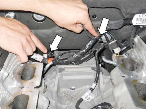
17 SECTION A DISASSEMBLY 27. Move the LH heater hose aside from the support bracket on top of the LH cylinder head. 28. Remove the two (2) nuts that secure the brake boost vacuum hose and heater hose support bracket to the LH cylinder head. 30. Remove the brake boost vacuum hose/line from the vehicle and set it aside. This line will be modified. SECTION A HOSE 1 SECTION B HOSE 2 HOSE 3 HOSE 5 HOSE Remove the LH heater hose support bracket and fuel rail cover from the LH side of the cylinder head. 29. Disconnect the brake boost vacuum hose from the port at the firewall. M-6066-M8627IM-BA (800) FORD788
 nuts and support bracket that retained")


18 SECTION A DISASSEMBLY 32. Remove the two (2) nuts and support bracket that retained the RH heater hose above the RH fuel rail. This hardware will not be reused. Remove the support bracket and fuel rail cover from the RH cylinder head. 33. Disconnect the heater feed and return hoses located at the front of both the LH and RH cylinder head intake flanges. Disconnect and remove the hoses from the ports on the RH firewall. 34. Disconnect the clamps on the hose ends and remove the 3/8" engine coolant degas hose from both the engine and the degas bottle. LH M-6066-M8627IM-BA (800) FORD788

 fuel injector electrical connectors (four [4] on each side). 38.")


19 SECTION A DISASSEMBLY 35. Remove the four (4) fuel rail bolts. These bolts will be reused. NOTE: It is not necessary to remove the fuel rail from the intake manifold assembly. RH shown 37. Remove the line from retainer near the front of the RH cylinder head. LH RH 36. Disconnect the eight (8) fuel injector electrical connectors (four [4] on each side). 38. Remove the six (6) intake manifold mounting bolts. 39. Lift the intake manifold and fuel rail assembly straight up and pull it forward to access the harness connectors at the rear. Disconnect the CMCV harness connector. Cut the retaining clip to remove the harness. Use care Do not cut the harness. Disconnect the four (4) harness connectors. Release/remove the two (2) pushpins. M-6066-M8627IM-BA (800) FORD788


20 SECTION A DISASSEMBLY Connector Harness push pin retainer points on rear of intake Pin retainers on harness M-6066-M8627IM-BA (800) FORD788


21 SECTION A DISASSEMBLY 40. Remove the intake manifold and fuel rail assembly from the vehicle. This hardware will not be reused. 42. Disconnect the vent hose from the engine coolant degas bottle and at the water pump inlet. 41. Clean the intake mounting surfaces and apply tape over the open intake ports to prevent engine contamination. Degas vent Degas hose from bottom of bottle M-6066-M8627IM-BA (800) FORD788
 mounting bolts (10 mm socket) and remove the engine")


22 SECTION A DISASSEMBLY 43. Remove the two (2) mounting bolts (10 mm socket) and remove the engine coolant degas bottle. 44. Disconnect the clamp on the end of the upper radiator hose at the radiator. Use a rag to catch excess coolant. On the thermostat housing end of the hose, push the clip down on the connector and remove the upper radiator hose from the vehicle. 45. Loosen the water pump bolts. 46. Remove the Front End Accessory Drive (FEAD) belt. Rotate the FEAD Tensioner counterclockwise to release the belt tension and remove the belt. Set the belt aside as it will be reused. Some coolant will still be inside the hose. Use a rag to catch coolant when removing the hose. M-6066-M8627IM-BA (800) FORD788


 securing the shroud to")


23 SECTION A DISASSEMBLY LH bolt 47. Disconnect the electric fan harness connector on the cooling module. Remove the two (2) bolts (10 mm socket) securing the shroud to the cooling module, then remove the electric fan and shroud assembly from the vehicle. RH bolt Fan shroud electrical connector M-6066-M8627IM-BA (800) FORD788
 bolts securing the water pump pulley to")


24 SECTION A DISASSEMBLY 48. Remove the three (3) bolts securing the water pump pulley to the engine and remove the water pump pulley. 49. Cut and remove the A/C compressor belt. Discard belt. 3-harness clip points 51. Loosen the clamp and disconnect the coolant hose, at the outlet neck. NOTE: Make sure to remove coolant to keep components clean as you continue procedures. 50. Unclip the engine electrical harness retention clips that retain the engine harness to the top corners of the RH (passenger side) front cover. 52. Remove the two (2) bolts from the thermostat housing (8 mm socket). M-6066-M8627IM-BA (800) FORD788


 water pump")


25 SECTION A DISASSEMBLY 53. Remove the thermostat housing assembly and set it aside. 55. Place a clean towel in the water pump inlet cavity. 54. Remove the four (4) water pump mounting bolts (10 mm socket) and remove the water pump. Set both aside for re-use. 56. Cap or tape off the PCV port, heater feed tube and the heater core ports on the firewall. M-6066-M8627IM-BA (800) FORD788


26 SECTION A DISASSEMBLY 58. Tape off and block the thermostat housing ports. Use care to prevent coolant from leaking from the housing and hose. 57. Tape off the radiator hose port and inlet port. M-6066-M8627IM-BA (800) FORD788


27 SECTION B MODIFICATIONS SECTION B MODIFICATIONS The following section will guide you through the required modifications of existing components and build up of the assemblies used to complete the installation. With the exception of the wiring modifications and intercooler pump bracket mounting, all of this work can be performed away from the vehicle. 5. Return to Section B of the hose/tube assembly. Carefully remove the foam sleeve from the brake aspirator. BRAKE BOOSTER VACUUM AND ASPIRATOR HOSE ASSEMBLY MODIFICATION 1. Retrieve the brake vacuum hose and aspirator assembly and place it on a work bench. 2. Disassemble the vacuum hose assembly and lay it out on the bench as shown in the following steps. SECTION A HOSE 1 SECTION B HOSE 3 HOSE 5 HOSE 2 6. Release the clamp and separate Section B, hose 2, from the steel tube. Disassemble the remaining brake aspirator assembly. Keep all clamps since they will be reused. HOSE 4 3. Release the clamp and remove Section A, hose 1, from the brake booster hose and aspirator assembly. Keep all clamps, they will be reused. 4. Release the clamp and remove the check valve from the straight end of hose 1. CHECK VALVE STRAIGHT END 7. Use the supplied brake aspirator plug (CS2575) to plug the black port that is diagonal to the 1/2- inch grey port of the aspirator assembly. (The arrow indicates the 1/2 inch grey port.) CURVED END M-6066-M8627IM-BA (800) FORD788


 into the black port on the brake")


28 SECTION B MODIFICATIONS 8. Use the takeoff clamps and attach them to the aspirator to brake booster hose (1315-9D690). 10. Install the line that goes from the supercharger to the aspirator assembly (1315-9D692) into the 1/2- inch grey fitting on the aspirator assembly. 9. Install the aspirator to brake booster line (1315-9D690) into the black port on the brake aspirator assembly. Then install the check valve that plugs into the brake booster. 11. Install the hose that goes to the clean air tube (1315-9D691) into the remaining port on the brake aspirator assembly. M-6066-M8627IM-BA (800) FORD788


 over the 36\" length of 3/8\" Rubber Hose")
29 SECTION B MODIFICATIONS 12. Re-install the foam on the brake aspirator assembly as shown. EVAPORATIVE EMISSIONS CANISTER PURGE LINE 1. Remove the convolute and carefully cut the quick connect fittings from both ends of the old EECPV line. 2. Install the Protective Hose Sleeve ( K579SLV) found in Hardware Kit D (1315-TVSHKD) over the 36" length of 3/8" Rubber Hose (1315-9G271). M-6066-M8627IM-BA (800) FORD788

 on the top of the fan shroud and align it with the shroud features.")

 rectangular areas marked as well as the two (2) holes. 3.")
30 SECTION B MODIFICATIONS 3. Install one (1) Clamp (7329K11) found in Hardware Kit D (1315-TVSHKD) onto each end of the new line. Install the quick connect fittings on the ends of the new line using the orientation shown. Secure the fittings with the clamps. 4. Paint the cut area with suitable material to prevent corrosion. ELECTRIC FAN SHROUD MODIFICATION 1. Place the IC degas bottle template (1315-DGSTMPL) on the top of the fan shroud and align it with the shroud features. Use a springloaded punch or other suitable tool to mark the fan shroud for modification. Remove the template. K-BRACE MODIFICATION 1. As described previously, mark the K-brace where it meets the windshield wiper close-out panel. 2. Use a suitable tool to cut the K-brace in the area marked. 2. Use a dremel or other suitable tool to remove material in the three (3) rectangular areas marked as well as the two (2) holes. 3. Use a suitable tool to file the sharp end where the brace was cut. 3. Install two (2) J-Clips (N M6) found in Hardware Kit H (1315-TVSHKH) in the two (2) areas on the edge of the shroud. Exposed point on modified K-brace, shown installed M-6066-M8627IM-BA (800) FORD788
 bosses located at A and B need to be reduced in height such that they are flush, or lower than the height of the nearby rib structure.")
 found in Hardware Kit H (1315-TVSHKH) onto the tab on the bottom of the Intercooler Degas Bottle (1315-8D080). Before B C 5.")

31 SECTION B MODIFICATIONS 3. Using a grinder or cut-off wheel, modify the front cover in the areas shown. The two (2) bosses located at A and B need to be reduced in height such that they are flush, or lower than the height of the nearby rib structure. The boss located at C needs to be reduced in height and cut in half. B C A 4. Insert the Clip (20860) found in Hardware Kit H (1315-TVSHKH) onto the tab on the bottom of the Intercooler Degas Bottle (1315-8D080). Before B C 5. Position the intercooler degas bottle to the fan shroud and check the fit, but do not install. Remove additional material as required so the bottle fits properly. A FRONT COVER MODIFICATION Wear safe eye protection when grinding to prevent serious personal injury. 1. If not already done so, clean the engine surfaces with brake clean and dry with shop air. 2. Block off the grinding area to prevent debris and metal shavings from spreading through the engine compartment. After Surfaces A and B, must be lower than or equal to the adjacent rib height. Cut in half and remove material off of boss C until flush. Refer to the following closeup example views for detail. Crosshatched surfaces A and B must be lower than or equal to this rib height. M-6066-M8627IM-BA (800) FORD788


32 SECTION B MODIFICATIONS 4. Remove the wiring retention clip from the feature on the front cover and set aside. 6. Deburr any rough edges on the cover and remove the retention harness from the wire harness. INTAKE VALLEY MODIFICATION 1. Mark the boss in the intake valley behind the water pump mounting location as shown. 5. Using a suitable cutting tool, remove the mounting tab. Follow the edge of the part. Use caution as to not contact the cam covers. 2. Use a grinder or suitable tool to grind the boss down across the entire length. Make sure to take off material uniformly along the angle. If high spots are left, the intake manifold will not seat properly on the engine. M-6066-M8627IM-BA (800) FORD788
 (6- wire) connector and harness at the")

33 SECTION B MODIFICATIONS 3. Vacuum out metal shavings. TPS/ETC WIRING 1. Locate the Throttle Position Sensor (TPS) (6- wire) connector and harness at the front of the passenger side cylinder head. Using a proper depinning tool, pop out the locking tab and remove the connector from the harness. M-6066-M8627IM-BA (800) FORD788
34 SECTION B MODIFICATIONS A B REMOVE MATERIAL OFF OF BOSS C UNTIL THE 20 MM HEIGHT IS ACHIEVED 20 MM M-6066-M8627IM-BA (800) FORD788


 from Hardware Kit E (1315-TVSHKE) to the newly installed connector.")
35 SECTION B MODIFICATIONS 2. Depress the locking tab and separate the empty female 1 x 6 connector from the new TPS/ETC Extension Harness (131114A595). It will be used in the next step. 3. Populate the new connector such that the yellow with violet wire is in position 1, the blue with green wire is in position 2, the brown wire is in position 3, the blue with orange wire is in position 4, the yellow wire is in position 5 and the green with violet wire is in position 6. Install the red plastic lock into the connector to secure the wires in place. 4. Connect the TPS/ETC Extension Harness (131114A595) from Hardware Kit E (1315-TVSHKE) to the newly installed connector. The wire colors on each side of the connector pair should align. Route the harness along the main wiring harness to the rear of the driver side cam cover. Use tape or zip ties to secure the extension harness to the main harness. M-6066-M8627IM-BA (800) FORD788
 at the front of")

.")

36 SECTION B MODIFICATIONS EVAPORATIVE EMISSIONS CANISTER PURGE VALVE WIRING 1. Locate the Evaporative Emissions Canister Purge Valve electrical connector (2-wire) at the front of the passenger side cylinder head. Use a proper de-pinning tool to remove the connector from the harness. 2. Depress the locking tab and separate the empty female 1 x 2 connector from the Evaporative Emissions Canister Purge Valve Extension Harness (13119G866). This connector replaces the connector removed in the previous step. Carefully pull the white locking tab forward to allow wires to be installed into the connector. Populate the new connector such that the white with brown wire is in position 1 and the green wire is in position 2. Depress the white locking tab to secure the wires. M-6066-M8627IM-BA (800) FORD788
 to the newly installed connector.")


 located at the rear of the driver side cylinder head. TPS/ETC AND EECPV HARNESS ROUTING 1.")
37 SECTION B MODIFICATIONS 3. Connect the Evaporative Emissions Canister Purge Valve Extension Harness (13119G866) to the newly installed connector. The wire colors on each side of the connector pair should align. Route the harness along the main wiring harness to the rear of the passenger side cam cover. Use tape or zip ties to secure the extension harness to the main harness. 3. Route the extension wiring harness to the RH side cylinder head. 4. Install the Connector Block ( A464), found in Hardware Kit E (1315-TVSHKE), into the IMRC 3-pin sensor connector (dark grey) located at the rear of the driver side cylinder head. TPS/ETC AND EECPV HARNESS ROUTING 1. Remove the wiring retainer and clip on the engine harness. AIR CHARGE TEMPERATURE (ACT) WIRING 1. Locate the IMRC sensor connector (light grey) at the rear of the passenger side cylinder head. 2. Connect the IMRC sensor connector into the ACT Wiring Harness ( A690), found in Hardware Kit E (1315-TVSHKE). M-6066-M8627IM-BA (800) FORD788


38 SECTION B MODIFICATIONS 2. Route both extension harnesses along the engine harness. Secure them in place with zip ties. 3. When complete, the secured harnesses will look similar to this. Trim the excess length from the zip ties. M-6066-M8627IM-BA (800) FORD788
 blue CMCV connectors at")


39 SECTION B MODIFICATIONS 4. Wrap electrical tape around the two (2) blue CMCV connectors at the rear of the cylinder head as shown. 2. Peel back the insulation at the base of the ground wire that was attached to the stud on the front cover. Trim back part of the insulation until the ground wire is exposed. CMCV connectors taped up ENGINE HARNESS GROUND WIRE 1. Pry up the engine harness retainers at the RH front and side of the engine. 3. Separate the ground wire further back into the harness. This will create slack necessary for relocating the ground. 4. Rewrap the ground wire with electrical tape. M-6066-M8627IM-BA (800) FORD788
 retaining tabs and locate the hole")

")
. These parts can be found in Hardware Kit E (1315-TVSHKE). 6.")

40 SECTION B MODIFICATIONS INTERCOOLER PUMP WIRING Mustang 1. Lift up the fuse box by releasing the two (2) retaining tabs and locate the hole underneath the fuse box near the PCM. The intercooler pump relay will be attached at this location. 5. Use snips to cut off the bent metal tab on the end of the ground tab. 2. Install the relay and fuse from the Intercooler Pump Wiring Harness (1315-8W501) through the hole and secure it with one (1) M6 x 14 Bolt (N605771) and one (1) M6 Nut (W520412). These parts can be found in Hardware Kit E (1315-TVSHKE). 6. Using a step bit, drill the hole on the tab to enlarge the opening. The hole must be larger to accommodate a larger bolt. TIP: Hold the tab with pliers when drilling to keep the tab stationary. Relay bolt, front side M-6066-M8627IM-BA (800) FORD788


41 SECTION B MODIFICATIONS Relay mounting nut as viewed from inside the wheel well opening 3. Lay the intercooler pump wire harness along the engine harness, in back of the cylinder head to the driver side inboard cylinder head. Disconnect the radio capacitor and plug the intercooler pump harness in line with this connector. 5. Install the intercooler pump harness red power wire to the first post in the fuse box. Tighten the nut to 10 Nm. 6. Install the ground wire with the existing ground wire near the RH strut tower and retighten the bolt to 10 Nm. Coil up the extra wire slack. 4. Route the intercooler pump wire harness in back of the cylinder head along the RH engine harness to the area near the fuse box. M-6066-M8627IM-BA (800) FORD788


 found in Hardware Kit E (1315-TVSHKE).")

42 SECTION B MODIFICATIONS 7. Route and tuck the intercooler pump harness under the engine harness and down the RH coil cover towards the fuse box as shown. Secure it in place with zip ties. 8. Retain the engine harness to the front cover using the zip tie with fur tree ( ) found in Hardware Kit E (1315-TVSHKE). 9. Route the intercooler pump wire harness over the top and in front of the wiper washer bottle. Secure it in place with zip ties as necessary. M-6066-M8627IM-BA (800) FORD788
 to each stud protruding from the")

 to two (2) M6 nuts (W520412) and secure to the studs. 3.")

43 SECTION B MODIFICATIONS 10. Zip tie the excess harness out of the way and secure it to a safe location Mustang 1. Install the relay and fuse from the intercooler pump wiring harness (1315-8W501) to each stud protruding from the battery box. Put the relay on the upper stud, and the fuse on the lower stud as shown. 5. Route the intercooler pump wire harness in back of the cylinder head along the RH engine harness to the area near the fuse box. 6. Install the intercooler pump harness red power wire to the first post in the fuse box. Tighten the nut to 10 Nm. 2. Apply blue Loctite (or equivalent) to two (2) M6 nuts (W520412) and secure to the studs. 3. Torque to 5-10 Nm. 4. Lay the intercooler pump wire harness along the engine harness, in back of the cylinder head to the drivers side inboard cylinder head. Disconnect the radio capacitor and plug the intercooler pump harness in line with this connector. M-6066-M8627IM-BA (800) FORD788

 found in Hardware Kit E (1315-TVSHKE).")
 sensor wires further up the harness in order to gain the necessary slack for proper sensor positioning towards the side of the engine")
44 SECTION B MODIFICATIONS 7. Install the ground wire with the existing ground wire near the RH strut tower and retighten the bolt to 10 Nm (coil up extra wire slack). 8. Route and tuck the intercooler pump harness under the engine harness and down the RH coil cover towards the fuse box as shown. Secure it in place with zip ties. 10. Route the intercooler pump wire harness over the top and in front of the wiper washer bottle. Secure it in place with zip ties as necessary. 9. Retain the engine harness to the front cover using the zip tie with fur tree ( ) found in Hardware Kit E (1315-TVSHKE). KNOCK SENSOR ORIENTATION ADJUSTMENT The knock sensors must be reoriented and the harnesses rewrapped to accommodate the new fuel charging assembly. It will be necessary to split the two (2) sensor wires further up the harness in order to gain the necessary slack for proper sensor positioning towards the side of the engine valley. 1. Remove the 90-degree plastic wiring retainer clipped to the connector and taped to the wiring convolute. M-6066-M8627IM-BA (800) FORD788

 bolts which retain the knock sensors to the engine block (10 mm socket).")


45 SECTION B MODIFICATIONS RH and LH knock sensors as far as possible to the outside of the valley of the block. Check that the sensors lay low on the engine valley so they will not interfere with the fuel charging assembly once it is installed. 2. Loosen the two (2) bolts which retain the knock sensors to the engine block (10 mm socket). If necessary, one (1) of the bolts and sensors can be removed for this modification process. 3. Peel back the tape from the connectors and remove the convolute approximately 1-1/2" past where they meet at the harness. 5. Reinstall the convolute and rewrap the wires with electrical tape as required. 6. Install the knock sensors in position. Install the bolts and torque them to Nm. CHANGING THE FACTORY SPARK PLUGS 1. Remove the coil covers by gently pulling up on them. Remove the oil cap prior to removing the RH coil cover. 2. Disconnect the electrical connectors for each ignition coil (eight [8] places). 4. Temporarily fit the sensors as follows to determine where to rewrap the wires. Install and rotate the M-6066-M8627IM-BA (800) FORD788
 factory spark")

. Save the fasteners for re-use. 6.")


46 SECTION B MODIFICATIONS 5. Use a 5/8" spark plug socket and 6" extension to remove the eight (8) factory spark plugs and set aside. These will not be re-used. NOTE: Use a universal swivel socket at the rear RH plug. 3. Remove the eight (8) fasteners holding the coil on plug assemblies in place (8 mm socket). Save the fasteners for re-use. 6. Unpack the eight (8) provided Spark Plugs (BL3E ) which are pre-gapped to 0.9 mm. Check to ensure the gap is intact and none are damaged. 4. Remove the coil on plug assemblies and label them so they can be reinstalled in their original position. A slight twisting motion will break the seal and ease removal. 7. Install the new spark plugs using a 5/8" spark plug socket and 6" extension. Torque to 14 Nm. NOTE: Use a universal swivel socket for the RH rear plug. M-6066-M8627IM-BA (800) FORD788


47 SECTION B MODIFICATIONS 9. Connect the electrical connectors for each ignition coil eight (8) places. 8. Apply a small amount of dielectric grease to the inside of the coil on plug boots before attaching to the spark plugs. Install the ignition coil on plugs in their original position. Install the coil on plug bolts and torque to 6 Nm. 10. Re-install the coil on plug covers. Reinstall the oil cap after the RH cover is installed. M-6066-M8627IM-BA (800) FORD788
 Rubber Grommet (R07060107) found in Hardware Kit H (1315-TVSHKH) into each lower tab on the Low Temperature Radiator")
 on the bottom rear of the intake manifold")
 Sleeve (R07060108) found in Hardware Kit H (1315-TVSHKH) into each of the rubber grommets. SUPERCHARGER BUILDUP 1.")
 from the packaging.")
48 SECTION C SUBASSEMBLY SECTION C SUBASSEMBLY INTERCOOLER LOW TEMPERATURE RADIATOR (LTR) 1. Insert one (1) Rubber Grommet (R ) found in Hardware Kit H (1315-TVSHKH) into each lower tab on the Low Temperature Radiator (LTR) Assembly (1315-8K229). 2. Attach the rubber hose section from the PCV Purge Hose to the bubbler fitting (3/8" barb) on the bottom rear of the intake manifold (1315-9H487) and secure it with the supplied clamp. 2. Push one (1) Sleeve (R ) found in Hardware Kit H (1315-TVSHKH) into each of the rubber grommets. SUPERCHARGER BUILDUP 1. Remove the two (2) bolts and the Evaporative Emission Canister Purge Valve from the stock intake manifold (8 mm socket). Discard the bolts. INTAKE MANIFOLD BUILDUP 1. Remove the PCV Purge Hose (13116K817) from the packaging. Release the clamp and separate the rubber section of hose as shown. 2. Install the valve into the rear of the supercharger (1315-6F066) using two (2) M6 x 1.0 x 35.5mm Bolts (N808429) found in Hardware Kit B (1315-TVSHKB). Torque bolts to 8-12 Nm. M-6066-M8627IM-BA (800) FORD788
 found in Hardware Kit D (1315-TVSHKD) to the top")
 to the bottom fitting on the supercharger bypass")

 onto the top of the supercharger. FUEL RAIL ASSEMBLY 1.")
49 SECTION C SUBASSEMBLY 3. Connect the Supercharger Boost Bypass Actuator Hose (1315-9E498) found in Hardware Kit D (1315-TVSHKD) to the top port on the actuator and route to the small port on the supercharger. 5. Connect the Supercharger Bypass Reference Vacuum Line (7R3V-9E498) to the bottom fitting on the supercharger bypass actuator. NOTE: This line will later be routed underneath the heater hose and fuel line. 4. Connect the brake boost hose to the 90-degree tube at the rear of the supercharger and secure it with the clamp. This is hose 1 created from the brake boost vacuum and aspirator assembly modification process. 6. Install the supercharger badge (1315-6F066BDG) onto the top of the supercharger. FUEL RAIL ASSEMBLY 1. Carefully install the eight (8) new Anti-Rotation Fuel Injector Clips (1311-9C995) onto the new Fuel Injectors (13119F593K Fuel Injector Kit). M-6066-M8627IM-BA (800) FORD788

.")

 and")
 as shown.")

50 SECTION C SUBASSEMBLY 2. Apply assembly lube to the injector O-rings and install the injectors into the new Fuel Rail ( F792). NOTE: Verify that the anti-rotation clips are properly aligned and fully engaged into the fuel rail injector cups. AIRBOX ASSEMBLY 1. Insert the Dirty Air Duct (1315-9F763) and install it into the Lower Airbox Tray (1315-9A612) as shown. NOTE: These may be separated if needed to ease installation to the vehicle. 2. Insert the two (2) J-Clips (W520823) from Hardware Kit A (1315-TVSHKA) onto the airbox tray as shown. M-6066-M8627IM-BA (800) FORD788
 through the")
 onto the MAF tube and")


 and torque to 10 Nm (10 mm socket).")
51 SECTION C SUBASSEMBLY 3. Place the MAF Tube Assembly ( B579HC) through the opening of the airbox tray from the inside. 5. Install the Filter ( R) onto the MAF tube and secure it with the supplied clamp. Torque clamp to 3-5 Nm. 4. Align the holes on the MAF tube assembly with the J-Clips on the airbox tray. Install two (2) Bolts (W500224) (M8 X 25) from Hardware Kit A (1315-TVSHKA) and torque to 10 Nm (10 mm socket). 6. Remove the MAF sensor from the factory airbox lid. Retain the bolts for reuse. M-6066-M8627IM-BA (800) FORD788


 on the airbox tray.")
. 10.")
52 SECTION C SUBASSEMBLY 9. Remove the grommets and sleeves from the factory lower airbox. Install the grommets and sleeves onto the new airbox assembly. TIP: Remove the center bushing while installing the rubber grommet through the hole in the tab. Re-install the center bushing once the grommet is fully seated. 7. Transfer and install the factory MAF sensor into the MAF tube assembly using the original MAF sensor bolts (M4 X 0.7 X 10) and tighten with a T-20 Torx bit. Torque the screws to Nm. Be careful not to over tighten these screws. Wiggle the MAF sensor to ensure that it is properly fastened. 8. Install the Upper Airbox Cover ( ) on the airbox tray. Using a T-30 Torx head bit, install six (6) Bolts (W506976) from Hardware Kit A (1315-TVSHKA). 10. Remove the rubber mounting isolator from the bottom of the factory airbox and install it onto the mount on the bottom of the new airbox in the same orientation. M-6066-M8627IM-BA (800) FORD788


53 SECTION D INSTALLATION SECTION D INSTALLATION The following section will guide you through the final installation of the kit into the vehicle. If you need to stop during any part of the installation, make sure you cover any open ports in the cylinder heads or intake manifold to prevent foreign material from contaminating your engine. INDUCTION RESONANCE TUBE DELETE GROMMET 1. Obtain the Induction Resonance Tube Delete Grommet (W651016) from Hardware Kit A (1315-TVSHKA). 2. Install the Induction Resonance Tube Delete Grommet in the hole that was exposed when the resonance tube was removed. INTAKE MANIFOLD, FUEL RAILS, SUPERCHARGER, SPACER AND THROTTLE BODY 1. Remove the tape from the cylinder heads and clean the cylinder head to intake manifold mating surfaces. 2. Install the Fuel Charging Assembly (1315-9H487) and check to make sure it is seated completely. If not, remove it and grind the modified area in the engine valley again until the manifold seats properly. Grind area if intake won t seat 3. Install the engine harness ground wire tab at the RH front of the intake manifold using one (1) of the M6 x 1.0 x 40 mm Bolts (R ) found in Hardware Kit B (1315-TVSHKB). Do not tighten the fastener down until the next step. Zip tie the ground wire to the engine harness. M-6066-M8627IM-BA (800) FORD788
 found in Hardware Kit B (1315-TVSHKB) in the positions shown.")


54 SECTION D INSTALLATION 4. Install the other five (5) M6 x 1.0 x 40 mm Bolts (R ) found in Hardware Kit B (1315-TVSHKB) in the positions shown. Tighten the fasteners in two stages with the sequence shown. Stage 1; torque bolts to 10 Nm. Stage 2; tighten bolts an additional 45 degrees. Reinstall the engine wiring harness retention clips at the rear of the intake manifold GROUND WIRE UNDER #5 6 WIRING RETAINERS HERE 5. Check that the hose in back of the intake manifold is routed around the electrical harness and towards the RH cam cover Lube the lower fuel injector O-rings with assembly lube. Install the fuel rail and injectors into the intake manifold. Be sure each injector is properly seated into the intake manifold. Install the previously removed fuel rail mounting bolts. Tighten the fasteners in two stages with the sequence shown. Stage 1; torque bolts to 10 Nm. Stage 2; tighten bolts an additional 45 degrees Connect the ACT sensor from ACT Harness ( A690) to the intake manifold. M-6066-M8627IM-BA (800) FORD788
 M8 x 1.")
 into the")

 fuel injector")


55 SECTION D INSTALLATION 10. Install the ten (10) M8 x 1.25 x 53 Fasteners (N808130) provided found in Hardware Kit B (1315-TVSHKB) into the mounting holes. Torque fasteners to 25 Nm in the sequence shown (10 mm socket). 8. Connect the eight (8) fuel injector electrical connectors. 9. Carefully place the Supercharger Assembly (1315-6F066) on top of the intake manifold. Ensure that the supercharger is fully seated on the intake mounting dowels. Remove protective shipping covers M-6066-M8627IM-BA (800) FORD788
 onto the hub of the supercharger using the six (6) M6 x 16 Bolts (W500013) found in Hardware")


 found in Hardware Kit B (1315-TVSHKB) on the Throttle Body Spacer (1315-9P697) as shown.")
56 SECTION D INSTALLATION 11. Install the 85 mm Supercharger Pulley (1313-6K85) onto the hub of the supercharger using the six (6) M6 x 16 Bolts (W500013) found in Hardware Kit B (1315-TVSHKB). Apply a small amount of blue thread locking compound to each bolt and torque to 8-12 Nm. HINT: You may need to torque the supercharger pulley bolts once the FEAD belt is installed. 12. Install the brake aspirator hose assembly. Connect the hose (with 1/2" barbed fitting) from the supercharger to the 1/2" brake line and secure it with the attached clamp. 14. Inspect the installation of the brake boost vacuum and aspirator assembly in the vehicle to ensure there are no pinched hoses and the convolute is positioned to prevent hose abrasion from other components. 15. Install the Spacer-To-Supercharger Gasket (1315-9E152) found in Hardware Kit B (1315-TVSHKB) on the Throttle Body Spacer (1315-9P697) as shown. 16. Install the Spacer-To-Throttle Body Gasket (R ) found in Hardware Kit B (1315-TVSHKB) as shown. 13. Connect the check valve on the brake vacuum and aspirator assembly to the brake booster. M-6066-M8627IM-BA (800) FORD788
 on the throttle")
 found in Hardware Kit B (1315-TVSHKB) to")

.")

57 SECTION D INSTALLATION 19. Install the Throttle Body Assembly (R ) on the throttle body spacer. Use four (4) M6 x 32.5 mm Bolts (R ) found in Hardware Kit B (1315-TVSHKB) to secure the throttle body assembly to the spacer. Torque bolts to 10 Nm. 17. Mount the Throttle Body Spacer (1315-9P697) using four (4) M6 x 32.5 Fasteners (R ). These parts can be found in Hardware Kit B (1315-TVSHKB). Torque the fasteners to 10 Nm. 20. Install the ETC and TPS electrical connectors to the throttle body. 18. Connect the fuel supply line to the fuel rail and lock it into position. ETC M-6066-M8627IM-BA (800) FORD788


58 SECTION D INSTALLATION TPS 21. Plug the Evaporative Emission Canister Purge Valve Extension Harness (13119G866) electrical connector into the relocated Evaporative Emission Canister Purge Valve on the back of the supercharger. 22. Install the Evaporative Emission Canister Purge Valve Line to the body line tube below the brake booster. Slide the green clip to lock the connector. Route the rest of the line behind the cylinder head to the RH rear of the supercharger. 23. Connect the new Evaporative Emission Canister Purge Valve Line (1315-9G271), to the relocated Evaporative Emission Canister Purge Valve on the back of the supercharger. Slide the green clip to lock the connector. Make sure the hose is routed away from any hot surfaces. M-6066-M8627IM-BA (800) FORD788
 to the heater tube near the front of the LF cylinder head.")


 found in hardware kit D (1315-TVSHKD) over")
59 SECTION D INSTALLATION 24. Connect the Heater Hose Assembly ( K579) to the heater tube near the front of the LF cylinder head. 27. Install the heater hose connector to the bottom port (heater outlet) at the RH firewall. 25. Route the line around the front of the engine underneath the snout of the supercharger towards the heater core. Remove the top intercooler tube bolt and install the P-clamp tab using the fastener on the intercooler coolant inlet. 26. Route the hose along the RH fuel rail and down to the heater outlet at the firewall. 28. Install the 424mm length of protective hose sleeve ( K579) found in hardware kit D (1315-TVSHKD) over the RH factory heater hose and secure with tape on either end of the sleeve. Reinstall the RH factory heater hose to the tube at the RH front of the engine. M-6066-M8627IM-BA (800) FORD788

 to the PCV Valve on the RH cam cover and the port")


60 SECTION D INSTALLATION Outlet hose moved to show hose plug underneath 29. Route the hose along the top of the RH fuel rail and connect it to the top heater core port (inlet) on the RH firewall. 32. Connect the PCV Purge Line (13116K817) to the PCV Valve on the RH cam cover and the port on the RH side of the supercharger. 30. Secure the heater inlet hose to the new heater outlet hose assembly with zip ties. 31. Install the end of the PCV Purge Hose (13116K817) from the hose section previously disassembled onto the bottom rear fitting of the intake manifold. Install the clamp. NOTE: Make sure both sides of the heater hose connections are locked onto the fitting. Pull on the hose to make sure the connection are secured. FEAD ASSEMBLY 1. Remove the four (4) bolts and one (1) stud from the front cover as shown. ONE OF THESE TWO BOLTS WILL BE REUSED M-6066-M8627IM-BA (800) FORD788


 bolts only.")

 thermostat")
61 SECTION D INSTALLATION 2. Lube the water pump gasket. 4. Install the thermostat housing and hose assembly and secure it with the clamp. 3. Install the water pump on the front cover and install the three (3) bolts only. Leave out the bolt at the 10 o clock position. Torque the bolts to 25 Nm. 5. Install the two (2) thermostat housing mounting bolts and torque to 10 Nm. M-6066-M8627IM-BA (800) FORD788
, three (3) (black) M8x1.")
 as shown.")
 Idler Pulleys (953045) onto the machined posts of the Upper FEAD Bracket.")
62 SECTION D INSTALLATION 6. Install the Upper FEAD Bracket (1314-8B653U) using one (1) M8x1.25x57 bolt (that was removed in the step 1 of this section), three (3) (black) M8x1.25x60 bolt ( ) and two (2) M8x1.25x84 Bolts (W704752) from Hardware Kit C (1315-TVSHKC). Torque bolts to 25 Nm. 8. Route the FEAD Belt (K060806) as shown. Do not route the belt onto the supercharger pulley. 7. Install two (2) Idler Pulleys (953045) onto the machined posts of the Upper FEAD Bracket. Secure the pulleys using two (2) M8 x 1.25 x 28 mm Idler Bolts (R ) with washers found in Hardware Kit C (1315-TVHSKC). Torque bolts to 25 Nm (13 mm socket). M-6066-M8627IM-BA (800) FORD788
 found in Hardware Kit C (1315-TVSHKC).")
 M8 x 1.")
 Tensioner Bracket bolts to 25 Nm. 11.")
63 SECTION D INSTALLATION 9. Loosely install the FEAD Tensioner Bracket Assembly (13118B603) onto the front cover using two (2) M8 x 1.25 x 120 mm Bolts (N811329) found in Hardware Kit C (1315-TVSHKC). NOTE: Install the lowest bolt into the casting prior to positioning in vehicle, in order to clear the sway bar. 10. Install one (1) M8 x 1.25 x 41 mm Bolt (W705128) found in Hardware Kit C (1315-TVSHKC), to fasten the Tensioner Bracket to the Upper FEAD Bracket. Torque all three (3) Tensioner Bracket bolts to 25 Nm. 11. Using a 17 mm socket, rotate the new tensioner clockwise to install the belt on to the supercharger pulley. Inspect each pulley to ensure the belt is properly seated. Ensure all supercharger pulley bolts have been torqued to 10 Nm. M-6066-M8627IM-BA (800) FORD788
 ASSEMBLY 1. Raise the vehicle. 2.")
. 12. Re-install the water pump pulley using the three (3) removed bolts. Torque the bolts to 25 Nm. 13.")

64 SECTION D INSTALLATION USE THIS NUT TO ROTATE THE TENSIONER AND INSTALL THE FEAD BELT INTERCOOLER LOW TEMPERATURE RADIATOR (LTR) ASSEMBLY 1. Raise the vehicle. 2. If you have a performance pack car, remove the two (2) outboard bolts on the factory radiator support bracket (as viewed from below the vehicle). 12. Re-install the water pump pulley using the three (3) removed bolts. Torque the bolts to 25 Nm. 13. Re-install the stock FEAD Belt by rotating the tensioner counter-clockwise and routing the belt as per the stock Ford belt routing. 3. Install the Low Temperature Radiator (LTR) Assembly (1315-8K229) and secure the low temp radiator into position with the two M8 x 16 mm bolts included in hardware kit H. M-6066-M8627IM-BA (800) FORD788
 and LH LTR Support Bracket (1315-8K244) found in")

 through the J-Clip. Torque to 25 Nm.")

 on the upper LH side of the LTR radiator")
65 SECTION D INSTALLATION 5. Install the RH LTR Support Bracket (1315-8K245) and LH LTR Support Bracket (1315-8K244) found in Hardware Kit H (1315-TVSHKH) on the lower tabs. Make sure to install the LH and RH in the correct position with the correct orientation. Secure each bracket at the radiator using a Bolt (W705128) and Nut (W520413). Secure each bracket to the chassis using a Bolt (W705128) through the J-Clip. Torque to 25 Nm. RH bracket 4. Install two (2) J-Clips (W520823) on both frame rail ends as shown. Some trimming of the J-Clip may be required to install the J-Clip through the hole in the frame. LH bracket 6. Temporarily install the LTR Outlet Hose (1315-8D030) on the upper LH side of the LTR radiator and route it to the intake manifold. Mark the LH radiator close-out panel where the hose should pass through. Use snips to cut a notch in the close-out panels as required for the hose to pass through. M-6066-M8627IM-BA (800) FORD788


 from Hardware Kit G (1315-TVSHKG). 11.")
66 SECTION D INSTALLATION LTR outlet hose (1315-8D030) 7. Reinstall the hose onto the LTR outlet, and recheck the hose fit. Adjust as necessary until the hose passes through the close-out panel without being kinked. 8. Once a proper fit is obtained, ensure the close-out panel is secure in place. 9. Install the LTR outlet hose through the close-out panel to the intake manifold. 10. Install the hose onto the LTR outlet and secure it with the Clamp (CT19X12) from Hardware Kit G (1315-TVSHKG). 11. Install the hose onto the intake manifold inlet and secure it with the Clamp (CT19X12) from Hardware Kit G (1315-TVSHKG). M-6066-M8627IM-BA (800) FORD788
 as a template, place the pump bracket")


 pilot holes.")

67 SECTION D INSTALLATION INTERCOOLER PUMP, MOUNTING BRACKET AND HOSES 1. Using the Intercooler Pump Bracket (1315-8C4191) as a template, place the pump bracket against the frame behind the wiper fluid reservoir mounting bracket as shown. Mark the holes for drilling and remove the intercooler pump bracket. NOTE: The bracket is placed on the outside of the frame behind the wiper pump reservoir bracket to make it easy to drill the holes. When installed, the intercooler pump and bracket will be mounted on the INSIDE of this section of the frame. 2. Start by drilling two (2) pilot holes. Then, drill out two (2) 3/8" holes. 3. Install the Intercooler Pump (F8YH-8501) into the Pump Retainer (R G) and onto the intercooler pump bracket. Secure the pump and retainer to the bracket using one (1) M6 x 16 Bolt (N605891). Torque the bolt to 10 Nm. M-6066-M8627IM-BA (800) FORD788


 5.")

68 SECTION D INSTALLATION TO LTR RADIATOR TO IC PUMP Pump hose outlet connection view 4. Place the intercooler pump assembly and bracket in mounting position with the pump in-board to the vehicle. Install two (2) Bolts (W500224) (M8 x 25) into the weld nuts. Torque to 25 Nm. Intercooler pump outlet hose (1315-6K236) 5. Install the intercooler pump outlet hose (1315-8K236) from the pump outlet, over the side of the frame rail and to the inlet on the lower RH side of LTR. Pump hose to LTR connection M-6066-M8627IM-BA (800) FORD788
 Clamp (CT19X12) from Hardware Kit G (1315-TVSHKG). CLAMP SECURING HOSE TO IC PUMP OUTLET 7.")


69 SECTION D INSTALLATION 6. Secure the hose to the pump using one (1) Clamp (CT19X12) from Hardware Kit G (1315-TVSHKG). Secure the hose to the LTR inlet using one (1) Clamp (CT19X12) from Hardware Kit G (1315-TVSHKG). CLAMP SECURING HOSE TO IC PUMP OUTLET 7. Connect the intercooler pump harness electrical connecter to the intercooler pump and secure it with a zip tie to the bracket. NOTE: Route all intercooler hoses very carefully. It is critical for intercooler performance that these hoses are not kinked once installed into the vehicle. ELECTRIC FAN, INTERCOOLER RESERVOIR AND HOSES 1. Install the electric fan in position and secure it with the two (2) mounting bolts previously removed. Torque to 10 Nm. 8. Collect the excess intercooler pump harness and secure it with zip ties as needed. M-6066-M8627IM-BA (800) FORD788
 installed during the electric fan modification is in place at the")
 onto the fan")
 M6 x 1.")
 to the bottom of the intercooler degas bottle")
70 SECTION D INSTALLATION 2. Connect the fan electrical connector. Fan electrical connector 3. Ensure that the Clip (20860) installed during the electric fan modification is in place at the bottom of the Intercooler Degas Bottle (1315-8D080). Intercooler pump inlet hose (1315-8D029) 5. Install the intercooler degas bottle with Intercooler Degas Bottle Cap (9C3Z-8101) onto the fan shroud J-Clips. Push the bottle into position. The clip on the bottom should retain the degas bottle in place. 6. Install two (2) M6 x 1.0 x 22 mm Mounting Bolts (N605891) found in Hardware Kit H (1315-TVSHKH) and torque to 10 Nm. 4. Install the Intercooler Pump Inlet Hose (1315-8D029) to the bottom of the intercooler degas bottle and secure it with the Clamp (CT19X12). M-6066-M8627IM-BA (800) FORD788
 from the bottom of the intercooler degas bottle to the intercooler")
 Clamp (CT19X12) from Hardware Kit G")
 to the outlet on the intercooler.")
 Clamp (CT19X12) from Hardware")
71 SECTION D INSTALLATION 7. Install the hose (1315-8D029) from the bottom of the intercooler degas bottle to the intercooler pump inlet. Secure the hose using (1) Clamp (CT19X12) from Hardware Kit G (1315-TVSHKG). 10. Install the hose to the intercooler cooler outlet using (1) Clamp (CT19X12) from Hardware Kit G (1315-TVSHKG). 8. Install the Intercooler Degas Bottle Inlet Hose (1315-8D031) to the outlet on the intercooler. INTERCOOLER OUTLET CONNECTION Outlet hose connection at top port of intercooler 9. Install the hose to the intercooler degas bottle inlet using (1) Clamp (CT19X12) from Hardware Kit G (1315-TVSHKG). RADIATOR HOSES, ENGINE DEGAS BOTTLE AND HOSES 1. Reconnect the coolant hose to the outlet on thermostat housing. M-6066-M8627IM-BA (800) FORD788


 onto the other end of the engine degas hose. 6.")

72 SECTION D INSTALLATION 4. Install the engine degas bottle hose on the rear of the bottle and to the upper LH radiator. Secure both ends of the hose with the clamps. 2. Reconnect the other end of the coolant hose to the upper RH inlet of the radiator. Secure it with the clamp. 5. Transfer the hose clamp from the bottle end of the factory degas hose to new 3/8" Engine Degas Hose ( ). Install the hose clamp (62002) onto the other end of the engine degas hose. 6. Install the 3/8" Engine Bottle Degas Hose from the engine degas bottle to the fitting by the driver side cylinder head on the coolant outlet neck. Tighten worm gear clamp torque to 3 Nm. 3. Reinstall the factory degas bottle onto the fan shroud and torque the bolts to 10 Nm. 7. Install the other end of the hose to the engine degas bottle as shown. Secure the constant tension clamp. M-6066-M8627IM-BA (800) FORD788


73 SECTION D INSTALLATION 8. Ensure that all intercooler hoses, the degas hose and all clamps and wiring have been installed to provide maximum clearance to the supercharger belt. AIR INDUCTION SYSTEM 1. Remove the old MAF wire harness clip christmas tree that retained the harness to the body. 3. Lower the airbox assembly into mounting position. Align the airbox assembly opening with the dirty air duct and press it into the dirty air tube until properly installed. A snap will be heard when properly seated. 4. Secure the airbox using the M6 bolt from the original airbox and torque to 10 Nm. 2. Install the Dirty Air Duct (1315-9F763) at the LH side of the radiator. M-6066-M8627IM-BA (800) FORD788
 in the vehicle")
. Torque clamps to 3 Nm. 6.")


74 SECTION D INSTALLATION 5. Install the Clean Air Tube (1315-9R504) in the vehicle using two (2) Hose Clamps (R ) from Hardware Kit A (1315-TVSHKA). Torque clamps to 3 Nm. 6. Install the PCV Fresh Air Inlet Tube ( ) by connecting the 90-degree fitting to the driver side cam cover and angled fitting to the PCV fitting in the clean air tube. 7. Route the MAF wire harness around the airbox assembly and connect the harness to the MAF sensor. Make sure the red lock is engaged on the connector. M-6066-M8627IM-BA (800) FORD788
 to the fitting on the clean air tube. 9.")

 pushpin retainers on the cowl trim panel. K-BRACE 1.")
75 SECTION D INSTALLATION 8. Connect the open end of the Supercharger Bypass Reference Line (7R3V-9E498) to the fitting on the clean air tube. 9. Connect the brake aspirator hose assembly (hose 3) to the fitting on the clean air tube. 2. Install the nuts on the studs and torque to 25 Nm using a 15 mm socket. 3. Install the five (5) mounting bolts and torque to 25 Nm using a 13 mm socket. 4. Reinstall the six (6) pushpin retainers on the cowl trim panel. K-BRACE 1. Once the supercharger installation process is complete, lift up the cowl trim panel and slide the modified K-brace underneath. Reinstall the K-brace over the studs and into position on the vehicle. M-6066-M8627IM-BA (800) FORD788


76 SECTION E FINAL ASSEMBLY SECTION E FINAL ASSEMBLY 1. Fill the engine cooling system (using a proper coolant mixture) to the marked level on the radiator degas bottle. 2. Using the same coolant mixture, fill the intercooler system. The coolant should be approximately one inch below the top of the cap. IMPORTANT: Both coolant systems can trap a large amount of air. It is very important to verify that the air is purged and that coolant is flowing properly through both systems. Ford Performance recommends vacuum filling both systems to properly evacuate the trapped air. 3. Reinstall lower close-out panel and inner fenders by reversing the removal procedures. 4. Reinstall the front wheels/tires. Torque wheel lugs to the factory Ford specifications. 5. Inspect all underhood wiring harnesses for potential interference issues. Use zip ties to safely position the harness away from any areas of concern. 6. Reinstall the radiator trim cover by reversing the removal instructions. DO NOT ATTEMPT TO REINSTALL THE PCM AND START THE VEHICLE IF THE PCM IS NOT EQUIPPED WITH A FORD PERFORMANCE CALIBRATION. OPERATING THE ENGINE WITHOUT THE RECALIBRATED PCM WILL RESULT IN ENGINE DAMAGE OR FAILURE AND WILL VOID THE WARRANTY. 7. Reinstall the battery connections by connecting the positive cable first then connecting the negative cable. Reinstall the battery cover panel with pushpins. 8. Reconnect the fuel pump control module electrical connector located under the backseat on the driver side. 9. Place the Belt Routing Diagram (13116E072) found in Hardware Kit F (1315-TVSHKF) on the underside of the hood, on the driver side, opposite of the factory Vehicle Emission Control Information decal. 10. Place the PCM Decal (R ) found in Hardware Kit F (1315-TVSHKF) in a visible location. 11. Place the PREMIUM FUEL ONLY Decal (13109A095) (white decal with black lettering) found in Hardware Kit F (1315-TVSHKF) on the arm door of the fuel filler door as shown. 12. Place the PREMIUM FUEL (R ) Clear Decal with white lettering on the instrument cluster bezel, on the flat area below the small center gauges as shown. PLACE DECAL HERE PLACE DECAL IN THIS AREA 13. Place the E.O. label (CM-EO-M8627) in a visible location under the hood. (Top of airbox lid or side of strut tower.) M-6066-M8627IM-BA (800) FORD788
L Mustang Phase 1 ROUSHcharger Kit Installation Instructions P/N: (R1315-P1CAL) EO D (EO not applicable with MY2016)
 EO D (EO not applicable with MY2016)") 2015-2016 5.0L Mustang Phase 1 ROUSHcharger Kit Installation Instructions P/N: 421823 (R1315-P1CAL) EO D-418-25 (EO not applicable with MY2016) 39555 Schoolcraft Rd, Plymouth MI, 48170 800.59.ROUSH 2015
2015-2016 5.0L Mustang Phase 1 ROUSHcharger Kit Installation Instructions P/N: 421823 (R1315-P1CAL) EO D-418-25 (EO not applicable with MY2016) 39555 Schoolcraft Rd, Plymouth MI, 48170 800.59.ROUSH 2015
M-6066-SGT (Black)/M-6066-SGTP (Polished) SVT Mustang Supercharger Upgrade Kit INSTALLATION INSTRUCTIONS
/M-6066-SGTP (Polished) SVT Mustang Supercharger Upgrade Kit INSTALLATION INSTRUCTIONS") Please contact the Techline for the most current instruction information (800) FORD788.!!! PLEASE READ THE FOLLOWING INSTRUCTIONS CAREFULLY PRIOR TO INSTALLATION!!! OVERVIEW: This kit is designed for use
Please contact the Techline for the most current instruction information (800) FORD788.!!! PLEASE READ THE FOLLOWING INSTRUCTIONS CAREFULLY PRIOR TO INSTALLATION!!! OVERVIEW: This kit is designed for use
Ford F L PHASE 2 ROUSHcharger Kit
 2011-2014 Ford F-150 6.2L PHASE 2 ROUSHcharger Kit P/N: 421432 (1162-P2CAL) EO # D-418-23 Installation Instructions Application: 2011-2014 Ford F-150 with 6.2L 2-Valve Engine w/ Automatic Transmission.
Installation Instructions
 2011+ Mustang GT Supercharger Kit(s) P/Ns: M-6066-MGT525D M-6066-MGT525PD M-6066-MGT624D M-6066-MGT624PD Installation Instructions Application: 2011+ Ford Mustang GT with 5.0L 4-Valve Engines w/ Manual
2018 Mustang 5.0L Cold Air Intake Installation Instructions P/N: ( )
") Installation Instructions P/N: 422086 (131850-9600) 39555 Schoolcraft Rd, Plymouth MI, 48170 800.59.ROUSH 2018 Mustang 5.0L Cold Air Intake Installation Instructions P/N: 422086 (131850-9600) Application:
Installation Instructions P/N: 422086 (131850-9600) 39555 Schoolcraft Rd, Plymouth MI, 48170 800.59.ROUSH 2018 Mustang 5.0L Cold Air Intake Installation Instructions P/N: 422086 (131850-9600) Application:
Mustang 5.0L Cold Air Intake Installation Instructions P/N:
 2015-2017 Mustang 5.0L Cold Air Intake Installation Instructions P/N: 421826 39555 Schoolcraft Rd, Plymouth MI, 48170 800.59.ROUSH 2015-2017 Mustang 5.0L Cold Air Intake Installation Instructions P/N:
2018 Mustang 5.0L Performance PAC1 Installation Instructions P/N: ( PERFPK1)
") 2018 Mustang 5.0L Performance PAC1 Installation Instructions P/N: 422113 (131850-PERFPK1) 39555 Schoolcraft Rd, Plymouth MI, 48170 800.59.ROUSH 2018 Mustang 5.0L Performance PAC1 Installation Instructions
2018 Mustang 5.0L Performance PAC1 Installation Instructions P/N: 422113 (131850-PERFPK1) 39555 Schoolcraft Rd, Plymouth MI, 48170 800.59.ROUSH 2018 Mustang 5.0L Performance PAC1 Installation Instructions
LChevrolet Camaro Supercharger Kit
 PART #92000A Important Notes: 2010-2013 6.2LChevrolet Camaro Supercharger Kit The use of fuel additives (ie. octane boosters) is not recommended. There is a possibility that these chemicals can damage
Ford F L Phase 1 ROUSHcharger Kit Installation Instructions P/N: (R1115-P1CAL-AA)
") 2015-2017 Ford F-150 5.0L Phase 1 ROUSHcharger Kit Installation Instructions P/N: 421983 (R1115-P1CAL-AA) 39555 Schoolcraft Rd, Plymouth MI, 48170 800.59.ROUSH 2015-2017 Ford F-150 5.0L Phase 1 ROUSHcharger
2015-2017 Ford F-150 5.0L Phase 1 ROUSHcharger Kit Installation Instructions P/N: 421983 (R1115-P1CAL-AA) 39555 Schoolcraft Rd, Plymouth MI, 48170 800.59.ROUSH 2015-2017 Ford F-150 5.0L Phase 1 ROUSHcharger
M-9424-M50CJ INTAKE MANIFOLD INSTALLATION INSTRUCTIONS
 Please visit www.fordracingparts.com for the most current instruction information!!! PLEASE READ ALL OF THE FOLLOWING INSTRUCTIONS CAREFULLY PRIOR TO INSTALLATION. AT ANY TIME YOU DO NOT UNDERSTAND THE
M-9603-CJ 123 mm Cold Air Kit for 5.4L 4V V8 Cobra Jet Mustang INSTALLATION INSTRUCTIONS
 Please contact the Techline for the most current instruction information 1-800-367-3788.!!! PLEASE READ THE FOLLOWING INSTRUCTIONS CAREFULLY PRIOR TO INSTALLATION!!! OVERVIEW: This kit is designed for
M-9603-SVT mm Cold Air Kit w/premium Calibration INSTALLATION INSTRUCTIONS
 Please visit www.fordracingparts.com for the most current instruction information!!! PLEASE READ ALL OF THE FOLLOWING INSTRUCTIONS CAREFULLY PRIOR TO INSTALLATION. AT ANY TIME YOU DO NOT UNDERSTAND THE
F L Ecoboost V F L Ecoboost V6 Performance Pac Level 2 Installation Instructions P/N: (1115TT-PWRPK2)
") 2015-2016 F-150 3.5L Ecoboost V6 2015-2017 F-150 2.7L Ecoboost V6 Performance Pac Level 2 Installation Instructions P/N: 422007 (1115TT-PWRPK2) 39555 Schoolcraft Rd, Plymouth MI, 48170 800.59.ROUSH 2015-2016
2015-2016 F-150 3.5L Ecoboost V6 2015-2017 F-150 2.7L Ecoboost V6 Performance Pac Level 2 Installation Instructions P/N: 422007 (1115TT-PWRPK2) 39555 Schoolcraft Rd, Plymouth MI, 48170 800.59.ROUSH 2015-2016
2018 Mustang Ecoboost Cold Air Intake P/N: ( ) Application: 2018 Ford Mustang 2.3L Manual or Automatic Transmission
 Application: 2018 Ford Mustang 2.3L Manual or Automatic Transmission") 2018 Mustang Ecoboost Cold Air Intake P/N: 422087 (131823-9600) Application: 2018 Ford Mustang 2.3L Manual or Automatic Transmission Installation Instructions Before installing your ROUSH Performance Product(s),
2018 Mustang Ecoboost Cold Air Intake P/N: 422087 (131823-9600) Application: 2018 Ford Mustang 2.3L Manual or Automatic Transmission Installation Instructions Before installing your ROUSH Performance Product(s),
M-9603-GTB 85 mm Cold Air Kit w/premium Cal. for 4.6L 3V V8 Mustang INSTALLATION INSTRUCTIONS
 Please contact the Techline for the most current instruction information 800-367-3788.!!! PLEASE READ THE FOLLOWING INSTRUCTIONS CAREFULLY PRIOR TO INSTALLATION!!! OVERVIEW: This kit is designed for use
2018 F L Cold Air Intake Installation Instructions P/N: ( )
") Installation Instructions P/N: 422088 (111850-9600) 39555 Schoolcraft Rd, Plymouth MI, 48170 800.59.ROUSH 2018 F-150 5.0L Cold Air Intake Installation Instructions P/N: 422088 (111850-9600) Application:
Installation Instructions P/N: 422088 (111850-9600) 39555 Schoolcraft Rd, Plymouth MI, 48170 800.59.ROUSH 2018 F-150 5.0L Cold Air Intake Installation Instructions P/N: 422088 (111850-9600) Application:
F L NA Cold Air Intake Installation Instructions P/N: ( )
") 2015-2017 F-150 3.5L NA Cold Air Intake Installation Instructions P/N: 421982 (111535-9600) 39555 Schoolcraft Rd, Plymouth MI, 48170 800.59.ROUSH 2015-2017 F-150 3.5L NA Cold Air Intake Installation Instructions
2015-2017 F-150 3.5L NA Cold Air Intake Installation Instructions P/N: 421982 (111535-9600) 39555 Schoolcraft Rd, Plymouth MI, 48170 800.59.ROUSH 2015-2017 F-150 3.5L NA Cold Air Intake Installation Instructions
Installation Instructions
 SLP GM/Chevrolet LS3 COIL COVER KIT 2010+ Camaro 5.3L/6.2L 2007+ GMT900 5.3L/6.2L PN: 620038 Installation Instructions Important Notes: Before installing your SLP Coil Cover Kit, please read the installation
Intake Manifold Removal
 PLEASE READ ALL OF THE FOLLOWING INSTRUCTIONS CAREFULLY PRIOR TO INSTALLATION. AT ANY TIME YOU DO NOT UNDERSTAND THE INSTRUCTIONS Parts included: -GT350 Intake manifold M-944-M5 -GT350 Air bucket w/filter.
2015 Mustang Ecoboost Cold Air Intake
 2015 Mustang Ecoboost Cold Air Intake Installation Instructions P/N: 421827 (131523-9A600) Application: 2015 Ford Mustang 2.3L Manual or Automatic Transmission Important Note: Before installing the ROUSH
F L and 2.7L Ecoboost V6
 2015-2016 F-150 3.5L and 2.7L Ecoboost V6 Installation Instructions P/N: 421981 (1115TT-9600) Application: 2015-2016 Ford F-150 2.7L Ecoboost V6, 2015-2016 Ford F-150 3.5L Ecoboost V6 Important Note: Before
M-9603-SVT mm Cold Air Kit w/premium Calibration INSTALLATION INSTRUCTIONS
 Please contact the Tech Line for the most current instruction information (800) 367-3788.!!! PLEASE READ THE FOLLOWING INSTRUCTIONS CAREFULLY PRIOR TO INSTALLATION!!! OVERVIEW: This kit is designed for
Mustang V-6 Cold Air Intake P/N: ( A600) Application: Ford Mustang 3.7L Manual or Automatic Transmission
 Application: Ford Mustang 3.7L Manual or Automatic Transmission") 2015-2017 Mustang V-6 Cold Air Intake P/N: 421828 (131537-9A600) Application: 2015-2017 Ford Mustang 3.7L Manual or Automatic Transmission Installation Instructions Before installing your ROUSH Performance
2015-2017 Mustang V-6 Cold Air Intake P/N: 421828 (131537-9A600) Application: 2015-2017 Ford Mustang 3.7L Manual or Automatic Transmission Installation Instructions Before installing your ROUSH Performance
Procharger Stage II Intercooled Supercharger System (11-14 GT)
") Procharger Stage II Intercooled Supercharger System (11-14 GT) Installation Time: Approximately one day. Installed on 2012 Mustang GT 5.0/Manual Required Tools 3/8 Socket Set (Standard and Metric) 1/2
Procharger Stage II Intercooled Supercharger System (11-14 GT) Installation Time: Approximately one day. Installed on 2012 Mustang GT 5.0/Manual Required Tools 3/8 Socket Set (Standard and Metric) 1/2
ROUSH Active IO Exhaust. Installation Instructions P/N: (R LITE) Fastback GT Convertible GT V8
 Fastback GT Convertible GT V8") Installation Instructions P/N: 422128 (R1318-5231LITE) Fastback GT Convertible GT V8 39555 Schoolcraft Rd, Plymouth MI, 48170 800.59.ROUSH ROUSH Active IO Exhaust Installation Instructions P/N: 422128
Installation Instructions P/N: 422128 (R1318-5231LITE) Fastback GT Convertible GT V8 39555 Schoolcraft Rd, Plymouth MI, 48170 800.59.ROUSH ROUSH Active IO Exhaust Installation Instructions P/N: 422128
2015+ F-150 Active Exhaust Kit Installation Instructions P/N: (1117-5E292LITE)
") 2015+ F-150 Active Exhaust Kit Installation Instructions P/N: 422104 (1117-5E292LITE) 39555 Schoolcraft Rd, Plymouth MI, 48170 800.59.ROUSH 2015+ Ford F-150 Active Exhaust Kit Installation Instructions
2015+ F-150 Active Exhaust Kit Installation Instructions P/N: 422104 (1117-5E292LITE) 39555 Schoolcraft Rd, Plymouth MI, 48170 800.59.ROUSH 2015+ Ford F-150 Active Exhaust Kit Installation Instructions
Mustang V-6 Level 1 Performance Pack Installation Instructions P/N: ( PWRPK1-AA)
") 2015-2017 Mustang V-6 Level 1 Performance Pack Installation Instructions P/N: 421999 (131537-PWRPK1-AA) 39555 Schoolcraft Rd, Plymouth MI, 48170 800.59.ROUSH 2015-2017 Mustang V-6 Level 1 Performance Pack
2015-2017 Mustang V-6 Level 1 Performance Pack Installation Instructions P/N: 421999 (131537-PWRPK1-AA) 39555 Schoolcraft Rd, Plymouth MI, 48170 800.59.ROUSH 2015-2017 Mustang V-6 Level 1 Performance Pack
2015+ Mustang GT V8 X-Pipe Exhaust Kit Installation Instructions P/N: (99-137)
") 2015+ Mustang GT V8 X-Pipe Exhaust Kit Installation Instructions P/N: 422046 (99-137) 39555 Schoolcraft Rd, Plymouth MI, 48170 800.59.ROUSH 2015+ Mustang GT V8 X-Pipe Exhaust Kit Installation Instructions
2015+ Mustang GT V8 X-Pipe Exhaust Kit Installation Instructions P/N: 422046 (99-137) 39555 Schoolcraft Rd, Plymouth MI, 48170 800.59.ROUSH 2015+ Mustang GT V8 X-Pipe Exhaust Kit Installation Instructions
2015+ Mustang GT V8 X-Pipe/H-Pipe Exhaust Kit Installation Instructions
 2015+ Mustang GT V8 X-Pipe/H-Pipe Exhaust Kit Installation Instructions P/N: 422046 and 422119 39555 Schoolcraft Rd, Plymouth MI, 48170 800.59.ROUSH 2015+ Mustang GT V8 X-Pipe/H-Pipe Exhaust Kit Installation
ROUSH Convertible Stylebar Installation Instructions P/N: (1315-STYLEBAR) Convertible Only
 Convertible Only") Installation Instructions P/N: 421911 (1315-STYLEBAR) Convertible Only 39555 Schoolcraft Rd, Plymouth MI, 48170 800.59.ROUSH Installation Instructions P/N: 421911 (1315-STYLEBAR) Convertible Only Application:
Installation Instructions P/N: 421911 (1315-STYLEBAR) Convertible Only 39555 Schoolcraft Rd, Plymouth MI, 48170 800.59.ROUSH Installation Instructions P/N: 421911 (1315-STYLEBAR) Convertible Only Application:
2015+ Mustang Rear Valance Installation Instructions P/N: (R F953) (R F953BS)
 (R F953BS)") 2015+ Mustang Rear Valance Installation Instructions P/N: 421894 (R1315-17F953) 421919 (R1315-17F953BS) 39555 Schoolcraft Rd, Plymouth MI, 48170 800.59.ROUSH 2015+ Mustang Rear Valance Kit Installation
2015+ Mustang Rear Valance Installation Instructions P/N: 421894 (R1315-17F953) 421919 (R1315-17F953BS) 39555 Schoolcraft Rd, Plymouth MI, 48170 800.59.ROUSH 2015+ Mustang Rear Valance Kit Installation
INSTALLATION GUIDE HOLDEN COLORADO (RG) INTERCOOLER KIT P/N PWI66175K INTERCOOLER P/N PWA64553 ( ) PIPE KIT
 INTERCOOLER KIT P/N PWI66175K INTERCOOLER P/N PWA64553 ( ) PIPE KIT") INSTALLATION GUIDE HOLDEN COLORADO (RG) INTERCOOLER KIT P/N PWI66175K INTERCOOLER P/N PWA64553 (2012-13) PIPE KIT ENGINEERING THE UNFAIR ADVANTAGE Contents CONDITIONAL MANUFACTURERS WARRANTY... 2 Warranty
INSTALLATION GUIDE HOLDEN COLORADO (RG) INTERCOOLER KIT P/N PWI66175K INTERCOOLER P/N PWA64553 (2012-13) PIPE KIT ENGINEERING THE UNFAIR ADVANTAGE Contents CONDITIONAL MANUFACTURERS WARRANTY... 2 Warranty
2012+ Focus Focus ST ROUSH Cold Air Induction Kit(s)
") 2012+ Focus 2013+ Focus ST ROUSH Cold Air Induction Kit(s) P/N: 421642 (1213NA-9600) 421609 (1213ST-9600) Installation Instructions Before installing your ROUSH Performance Product(s), read through the
2012+ Focus 2013+ Focus ST ROUSH Cold Air Induction Kit(s) P/N: 421642 (1213NA-9600) 421609 (1213ST-9600) Installation Instructions Before installing your ROUSH Performance Product(s), read through the
Installation Instructions
 2014+ Silverado Sierra 5.3L and 6.2L TVS1900 Supercharger Kit P/N: 620068 (2414-6006) 620072 (241462-6006) Installation Instructions Applications: 2014+ GMC Sierra and Chevrolet Silverado 1500 Trucks with
Mustang Hood Scoop
 Installation Instructions P/N: 421858 421859 421860 421861 421862 421863 421864 421865 421866 421867 421868 422055 422056 422057 39555 Schoolcraft Rd, Plymouth MI, 48170 800.59.ROUSH 2015-2017 Mustang
3.4L V6 SUPERCHARGER 7 TH INJECTOR KIT
 Part Number: 00602-17620-260 00602-17620-261 00602-17620-263 00602-17620-264 00602-17620-274 00602-17620-275 00602-17620-276 Section I Installation Preparation Kit Contents Item # Quantity Reqd. Description
M-9424-M50B 2012 Boss 302 Intake Manifold INSTALLATION INSTRUCTIONS
 !!! PLEASE READ ALL OF THE FOLLOWING INSTRUCTIONS CAREFULLY PRIOR TO INSTALLATION. WARNING: CUSTOM CALIBRATION REQUIRED! CALIBRATION NOT INCLUDED! KIT CONTENTS: 1) Intake Manifold Assembly 2) Assembly
2015+ Ford F-150 Off-Road Exhaust Kit
 2015+ Ford F-150 Off-Road Exhaust Kit Installation Instructions P/N: 421985 (1115-5E292ORR) Application: 2015+ Ford F-150 OFF-ROAD USE ONLY Important Note: Before installing the ROUSH Performance Product,
2018+ Mustang Hood Heat Extractors Installation Instructions P/N: (R C920)
") 2018+ Mustang Hood Heat Extractors Installation Instructions P/N: 422083 (R1318-16C920) 39555 Schoolcraft Rd, Plymouth MI, 48170 800.59.ROUSH 2018+ Mustang Hood Heat Extractors Installation Instructions
2018+ Mustang Hood Heat Extractors Installation Instructions P/N: 422083 (R1318-16C920) 39555 Schoolcraft Rd, Plymouth MI, 48170 800.59.ROUSH 2018+ Mustang Hood Heat Extractors Installation Instructions
INSTALLATION GUIDE NISSAN NAVARA INTERCOOLER KIT P/N PWI65094K
 INSTALLATION GUIDE NISSAN NAVARA INTERCOOLER KIT P/N PWI65094K ENGINEERING THE UNFAIR ADVANTAGE Contents CONDITIONAL MANUFACTURERS WARRANTY... 2 WARRANTY VOIDS... 2 WARRANTY DOES NOT COVER... 2 LIMIT OF
Edelbrock E-Force Supercharger Part #1538: Dodge 1500 Truck 5.7L V8 HEMI
 Edelbrock E-Force Supercharger Part #1538: 2009-2014 Dodge 1500 Truck 5.7L V8 HEMI 2009-14 Dodge 5.7L Hemi 1500 Truck INTRODUCTION Thank you for purchasing the Edelbrock Supercharger System for the 2009-15
2018+ Mustang Lower Grill and Chin Spoiler Kits Installation Instructions P/N: (R K945) P/N: (R F775)
 P/N: (R F775)") 2018+ Mustang Lower Grill and Chin Spoiler Kits Installation Instructions P/N: 422081 (R1318-17K945) P/N: 422082 (R1318-17F775) 39555 Schoolcraft Rd, Plymouth MI, 48170 800.59.ROUSH 2018+ Mustang Lower
2018+ Mustang Lower Grill and Chin Spoiler Kits Installation Instructions P/N: 422081 (R1318-17K945) P/N: 422082 (R1318-17F775) 39555 Schoolcraft Rd, Plymouth MI, 48170 800.59.ROUSH 2018+ Mustang Lower
2015 Mustang Heat Extractors Installation Instructions P/N: (R C920)
") Installation Instructions P/N: 421869 (R1315-16C920) 39555 Schoolcraft Rd, Plymouth MI, 48170 800.59.ROUSH 2015 Mustang Heat Extractors Installation Instructions P/N: 421869 (R1315-16C920) Application:
Installation Instructions P/N: 421869 (R1315-16C920) 39555 Schoolcraft Rd, Plymouth MI, 48170 800.59.ROUSH 2015 Mustang Heat Extractors Installation Instructions P/N: 421869 (R1315-16C920) Application:
Edelbrock E-Force Supercharger Stage II System Ford Mustang 4.6L Part # s: 15856
 2005-2009 Ford Mustang 4.6L Part # s: 15856 INTRODUCTION Thank you for purchasing the Edelbrock 4.6L Ford Supercharger System for the Mustang GT. The Edelbrock E-Force Supercharger System for the 2005-2009
2015 Mustang Fastback Rear Spoiler Installation Instructions P/N:
 Installation Instructions P/N: 421883 421884 421885 421886 421887 421888 421889 421890 421891 421892 421893 39555 Schoolcraft Rd, Plymouth MI, 48170 800.59.ROUSH 2015 Mustang Fastback Rear Spoiler Installation
2014 GM Truck Level 1 Performance Pack
 2014 GM Truck Level 1 Performance Pack Installation Instructions P/N: 2414-PRFPC1-AA Application: 2014+ Chevy Silverado and GMC Sierra 5.3L and 6.2L Important Note: Before installing your Blackwing cold
SLP Camaro ZL1 STAGE 3 (650 HP)
") SLP - 2012 Camaro ZL1 STAGE 3 (650 HP) PART #26002 PACKING LIST Before installation, use this check list to make sure all necessary parts have been included. ITEM QTY CHECK PART NUMBER DESCRIPTION 1. 1
SLP - 2012 Camaro ZL1 STAGE 3 (650 HP) PART #26002 PACKING LIST Before installation, use this check list to make sure all necessary parts have been included. ITEM QTY CHECK PART NUMBER DESCRIPTION 1. 1
Installation Instructions
 2012-2014 Ford F-150 ROUSH Phase 1 Kit 3.5L V6 Eco-Boost P/N: 421735 (1135-P1CAL) Installation Instructions Before installing your ROUSH Cold Air Kit, please read through the entire installation procedure
10-rib belt system upgrade Installation Manual
 10-rib belt system upgrade Installation Manual 2011-2017 and up Ford MUSTANG gt 5.0l coyote WHIPPLE SUPERCHARGERS 3292 NORTH WEBER AVE FRESNO, CA 93722 TEL 559.442.1261 FAX 559.442.4153 A color PDF of
2006 Honda Civic SI Supercharger Kit Installation Instruction Kit #
 2006 Honda Civic SI Supercharger Kit Installation Instruction Kit #350-091 3239 MONIER CIRCLE, STE.5 RANCHO CORDOVA, CA 95742 916.635.4550 FAX 916.635.4632 www.ct-engineering.com INS-157 VERSION: 3.25.2009
INTERCOOLED SUPERCHARGER SYSTEM FORD 5.4L 3V F-150 TRUCK
 Installation Instructions for: INTERCOOLED SUPERCHARGER SYSTEM 2004-2006 FORD 5.4L 3V F-150 TRUCK Step-by-step instructions for installing the best in supercharger systems. 89-89-65-001 Rev C Magnuson
Installation Instructions for: TOYOTA 4.5L SUPERCHARGER SYSTEM
 Installation Instructions for: TOYOTA 4.5L SUPERCHARGER SYSTEM 1995-1997 Land Cruiser * PREMIUM FUEL REQUIRED * Magnuson Products LLC 1990 Knoll Drive, Bldg A, Ventura, CA 93003 (805) 642-8833 phone *
10-RIB BELT SYSTEM UPGRADE INSTALLATION MANUAL
 10-RIB BELT SYSTEM UPGRADE INSTALLATION MANUAL 2011-2017 AND UP FORD MUSTANG GT 5.0L COYOTE WHIPPLE SUPERCHARGERS 3292 NORTH WEBER AVE FRESNO, CA 93722 TEL 559.442.1261 FAX 559.442.4153 WWW.WHIPPLESUPERCHARGERS.COM
ENGINE DEVELOPMENT INC.
 2003 Ford Expedition 4.6L& 5.4L We encourage you to read this manual thoroughly before you begin work, and perform the following: 1. A quick parts check to make certain your kit is complete. If you discover
1999 E-Series Workshop Manual
 http://www.fordservicecontent.com/pubs/content/~wsxm/~mus~len/21/sxm31c16.h... Page 1 of 3 SECTION 303-01C: Engine 6.8L 1999 E-Series Workshop Manual IN-VEHICLE REPAIR Procedure revision date: 06/30/1998
Always wear safety glasses when working on your vehicle.
 90-93 MAZDA MIATA SUPERCHARGER KIT The KraftWerks 90-93 Mazda Miata Supercharger Kit was designed for easy installation. Competent mechanics with the appropriate tools will find the process to be relatively
ENGINE ASSEMBLY STOCK TO 250 HP
 GM SPORT COMPACT Performance Build Book 25 ENGINE ASSEMBLY STOCK TO 250 HP Fig. 3 The stock ECOTEC engine has proven reliable to 250 hp.(fig. 3) Performance upgrades are available from GM Performance Parts
INSTALLATION INSTRUCTIONS STILLEN SUPERCHARGER KIT Nissan 350Z P/N &
 Equipment needed: 1. Assorted sockets and wrenches 2. +,- Screwdrivers 3. Assorted pliers/ Clamps 4. Wire cutting/crimping tools 5. Thread locking compound (blue) 6. Solder gun/ shrink wrap (optional)
Installation Instructions Part Number
 Installation Instructions Part Number 84152143 Thank you for choosing Chevrolet Performance as your high performance source. Chevrolet is committed to providing proven, innovative performance technology
ROUSH FUEL SYSTEM UPGRADE CURRENT FORD MUSTANG 5.0L
 ROUSH FUEL SYSTEM UPGRADE 2011- CURRENT FORD MUSTANG 5.0L P/N: 421602 (1313-FPVRKIT) Installation Instructions Before installing your ROUSH Performance Product(s), read through the entire installation
2015 Corvette Supercharger System Instructions
 2015 Corvette Supercharger System Instructions These instructions are meant to serve as a guide to the installation of the ECS 2015 Corvette Supercharging system. Please be sure to use all safety equipment
BLACKBIRD INSTALLATION SUPPLEMENT
 BLACKBIRD INSTALLATION SUPPLEMENT FOR 2003-7 FORD 6.0 LITER DIESEL SINGLE ALTERNATOR F-350, F-450, F-550, EXCURSION VERSION 7-07 Parts Description Blackbird Wiring Manual Installation Supplement 6.0 Liter
INSTALLATION INSTRUCTIONS AIR/OIL SEPARATOR KIT
 INSTALLATION INSTRUCTIONS AIR/OIL SEPARATOR KIT 2015+ SUBARU WRX (LHD ONLY) Document: 19-0136 Support: info@radiumauto.com This document covers the installation of the Radium brake master cylinder brace
BBK Intake Manifold Kit ( L) - Installation Instructions
 - Installation Instructions") BBK Intake Manifold Kit (86-93 5.0L) - Installation Instructions The below installation instructions work for the following products: BBK Intake Manifold Kit (86-93 5.0L) Please read through the instructions
BBK Intake Manifold Kit (86-93 5.0L) - Installation Instructions The below installation instructions work for the following products: BBK Intake Manifold Kit (86-93 5.0L) Please read through the instructions
Installation manual BMW E TS1/TS2
 Installation manual BMW E46 330 TS1/TS2 Technical support Europe: +4741558555 Technical support USA: (858)314-2954 Email support: support@esstuning Installation manual BMW E46 330 TS1/TS2 Remove and send
Lower Intake Manifold Replacement
 Lower Intake Manifold Replacement Removal Procedure 1. Turn OFF all the lamps and the accessories. 2. Ensure the ignition switch is in the OFF position. 3. Disconnect the negative battery cable from the
Edelbrock 5.0L Mustang GT Supercharger Part #1588 & 1589
 Edelbrock 5.0L Mustang GT Supercharger Part #1588 & 1589 INTRODUCTION Edelbrock 5.0L Ford Supercharger System Thank you for purchasing the Edelbrock 5.0L Ford Supercharger System for the Mustang GT. The
1. With the vehicle in NEUTRAL, position it on a hoist. For additional information, refer to Section
 SECTION 303-01C: Engine 5.4L (4V) 2009 Mustang Workshop Manual REMOVAL Procedure revision date: 07/25/2008 Engine Special Tool(s) Heavy Duty Floor Crane 014-00071 or equivalent Lifting Bracket, Engine
L Intake Manifold Part #
 86-93 5.0L Intake Manifold Part #5001-5002 I N S T A L L A T I O N I N S T R U C T I O N S Supplied Materials Bottom cover, Upper manifold, Lower manifold, Plenum cover plate, 1501 Throttle body (comes
Front Fascia Kit Installation Instructions P/N:
 Installation Instructions P/N: 421843 421844 421845 421846 421847 421848 421849 421850 421851 421852 421853 39555 Schoolcraft Rd, Plymouth MI, 48170 800.59.ROUSH 2015-2017 Front Fascia Kit Installation
ROUSH Active Exhaust. Installation Instructions P/N: (R AVC) Fastback GT V8 - Convertible GT V8
 Fastback GT V8 - Convertible GT V8") Installation Instructions P/N: 422100 (R1318-5231AVC) Fastback GT V8 - Convertible GT V8 39555 Schoolcraft Rd, Plymouth MI, 48170 800.59.ROUSH ROUSH Active Exhaust Installation Instructions P/N: 422100
Installation Instructions P/N: 422100 (R1318-5231AVC) Fastback GT V8 - Convertible GT V8 39555 Schoolcraft Rd, Plymouth MI, 48170 800.59.ROUSH ROUSH Active Exhaust Installation Instructions P/N: 422100
Weistec M113K Supercharger System Installation Guide
 Weistec M113K Supercharger System Installation Guide WARNING! DO NOT HAVE YOUR ECU REPROGRAMMED ANYWHERE BUT AT WEISTEC FOR THIS SUPERCHARGER. THE AMG 55 USES AN ELECTRONIC THROTTLE CONTROL (ETC), WHICH
Zoom and Print Options
 Vehicle» Engine, Cooling and Exhaust» Engine» Service and Repair» Removal and Replacement» Engine Replacement Engine Replacement ^ Tools Required - J 38185 Hose Clamp Pliers Removal Procedure 1. Remove
05-08 GT. Hellion Power Systems Mustang Kit Instructions
 Hellion Power Systems 05-08 Mustang Kit Instructions 1. Disconnect Battery 2. Drain Radiator, keep fluid for re-installation. 3. Remove air box and inlethoses. 6. Next, underneath, punch oil pan for turbo
2015+ Mustang I-4 Y-Pipe Exhaust Kit Installation Instructions P/N: (1315-5G206)
") 2015+ Mustang I-4 Y-Pipe Exhaust Kit Installation Instructions P/N: 422091 (1315-5G206) 39555 Schoolcraft Rd, Plymouth MI, 48170 800.59.ROUSH 2015+ Mustang I-4 Y-Pipe Exhaust Kit Installation Instructions
2015+ Mustang I-4 Y-Pipe Exhaust Kit Installation Instructions P/N: 422091 (1315-5G206) 39555 Schoolcraft Rd, Plymouth MI, 48170 800.59.ROUSH 2015+ Mustang I-4 Y-Pipe Exhaust Kit Installation Instructions
2015+ Mustang Trunk Toolkit Installation Instructions P/N: (R1315-TOOLKIT)
") Installation Instructions P/N: 421910 (R1315-TOOLKIT) 39555 Schoolcraft Rd, Plymouth MI, 48170 800.59.ROUSH 2015+ Mustang Trunk Toolkit Installation Instructions P/N: 421910 (R1315-TOOLKIT) Important Note:
Installation Instructions P/N: 421910 (R1315-TOOLKIT) 39555 Schoolcraft Rd, Plymouth MI, 48170 800.59.ROUSH 2015+ Mustang Trunk Toolkit Installation Instructions P/N: 421910 (R1315-TOOLKIT) Important Note:
FREE $15 Gift Card for every $100 spent on Ship To Home orders. Find Out How
 1 of 29 10/12/2011 5:05 PM FREE $15 Gift Card for every $100 spent on Ship To Home orders. Find Out How Ford Ranger/Explorer/Mountaineer 1991-1999 Intake Manifold REMOVAL & INSTALLATION Print The engines
2017+ L5P Duramax 3 ½ Down Pipe & EGR Fix Kit
 2017+ L5P Duramax 3 ½ Down Pipe & EGR Fix Kit Covers installation of PN s: WCF100630, WCF100829 Note: This Kit is for off road competition use only! Off Road Competition Use Tuning & Exhaust System is
Installation Instructions
 VMP 2.3L TVS Supercharger Kit 11-14 GT/Boss 5.0 Installation Instructions Application: 2011-2014 Ford Mustang GT and Boss 302 with 5.0L 4-Valve Engine w/ Manual or Automatic 2015 Ford Mustang GT with some
Edelbrock E-Force Supercharger JEEP WRANGLER JK 3.6L V6 Part #1527 and 15270
 Edelbrock E-Force Supercharger 2012-14 JEEP WRANGLER JK 3.6L V6 Part #1527 and 15270 INTRODUCTION Thank you for purchasing the Edelbrock Supercharger System for the Jeep Wrangler with 3.6L V6 Pentastar.
Special Note About The JDM High Performance Water Pump:
 Page 1 of 30 JDM Engineering, Inc. home Call Us! 732-780- 0770 back to Installation Instructions Electric Fan Upgrade Kit Electric Fan Wiring Diagram Thank you for your purchase of the JDM Engineering
SL63 Weistec M156 Supercharger System Installation Guide Stage 1 / Stage 2
 SL63 Weistec M156 Supercharger System Installation Guide Stage 1 / Stage 2 WARNING! DO NOT HAVE YOUR ECU REPROGRAMMED ANYWHERE BUT AT WEISTEC FOR THIS SUPERCHARGER. THE AMG 63 USES AN ELECTRONIC THROTTLE
Installation Instructions for Lingenfelter GM 2500 Suburban & Yukon XL Auxiliary Fan System (with AC clutch controlled fan output)
") Installation Instructions for Lingenfelter 2007-2013 GM 2500 Suburban & Yukon XL Auxiliary Fan System (with AC clutch controlled fan output) PN L300080607 Revision - 1.1 Lingenfelter Performance Engineering
Installation Instructions for Lingenfelter 2007-2013 GM 2500 Suburban & Yukon XL Auxiliary Fan System (with AC clutch controlled fan output) PN L300080607 Revision - 1.1 Lingenfelter Performance Engineering
#TL T EA888 GEN 3 FUELING SYSTEM/ INSTALLATION INSTRUCTIONS
 #TL100069 2.0T EA888 GEN 3 FUELING SYSTEM/ INSTALLATION INSTRUCTIONS Notes: These instructions were written for a North American specification MkVII GTI. Other models, like the Golf R, are similar. When
BLACKBIRD INSTALLATION SUPPLEMENT
 BLACKBIRD INSTALLATION SUPPLEMENT FOR 2003-7 FORD 6.0 LITER DIESEL F-SERIES DUAL ALTERNATOR VERSION 10/07 Blackbird Installation Supplement for Ford 6.0. Liter Dual Alternator Parts included in the 6.0
WARNING: ALWAYS relieve fuel pressure before disconnecting any fuel related component. DO NOT allow fuel to contact engine or electrical components.
 4.0L V8 - VINS [K,U] Selected Block 1990 Lexus LS 400 For Lextreme Powertrain 2020 S. Hacienda Blvd. # D Hacienda Heights California 91745 Copyright 1998 Mitchell Repair Information Company, LLC Friday,
WARNING: IF YOU ARE NOT EXPERIENCED IN THE AREA OF AUTOMOTIVE MECHANICS WE STRONGLY URGE THAT YOU REFER THIS INSTALLATION TO YOUR MECHANIC.
 INSTALLATION INSTRUCTIONS STILLEN SUPERCHARGER KIT 2003+ Infiniti G35 Materials supplied: See attached list Equipment needed: 1. Assorted sockets and wrenches 2. +,- Screwdrivers 3. Assorted pliers/ Clamps
Edelbrock E-Force Stage II Supercharger CHEVY CORVETTE C7 Z06 LT4 6.2L Part #157320
 2015-16 CHEVY CORVETTE C7 Z06 LT4 6.2L Part #157320 INTRODUCTION Thank you for purchasing the Edelbrock Stage II Supercharger System for the 2015-16 Chevy Corvette Z06 LT4. The Edelbrock E-Force Supercharger
Installation Instructions
 Ford F-650 Chassis Cab Liquid Propane Autogas Fuel System Dual and Single Tanks Revision History -AA Initial Release 10/2013 -AB SRM Isolator Delete 11/2014 -BA Add Single Tank Configuration 02/2015 Installation
APR, LLC
 + 1. 3 3 4. 5 0 2. 5 1 8 1 4 8 0 0 U S H W Y 2 8 0 W e s t, O p e l i k a, A l a b a m a 3 6 8 0 1 4 8 0 0 U S H W Y 2 8 0 W e s t, O p e l i k a, A l a b a m a 3 6 8 0 1 + 1. 3 3 4. 5 0 2. 5 1 8 1 NOTES:
Before installing your Roush Performance Product(s), read through the entire installation procedure and check to make sure all items are present.
, read through the entire installation procedure and check to make sure all items are present.") Ford Mustang Roush Fog Lamp Wiring Harness Installation Instructions Application: 2005 Ford Mustang GT Model (Designed for use with Roush Fog Lamps SM01-6400-AL) Before installing your Roush Performance
Ford Mustang Roush Fog Lamp Wiring Harness Installation Instructions Application: 2005 Ford Mustang GT Model (Designed for use with Roush Fog Lamps SM01-6400-AL) Before installing your Roush Performance
99-04 GT. Hellion Power Systems Mustang GT Kit Instructions
 Hellion Power Systems 99-04 Mustang GT Kit Instructions Part 1 Hellion recommends that the front suspension system be installed either by trained professionals or by 5.Remove rack bolts K-Member Installation
REMOVAL & INSTALLATION
 REMOVAL & INSTALLATION NOTE: For reassembly reference, label all electrical connectors, vacuum hoses and fuel lines before removal. Also place mating marks on engine hood and other major assemblies before
1 of 12 10/5/2015 8:11 AM
 1 of 12 10/5/2015 8:11 AM REMOVAL 1. Perform the fuel pressure release procedure See: Fuel Pressure Release > Procedures > Fuel System Pressure Release Procedure. 2. Recover the refrigerant from the refrigerant
SLS825 Weistec Supercharger System Installation Guide
 SLS825 Weistec Supercharger System Installation Guide 2010-Present SLS AMG (Gullwing and Roadster) 2014 SLS Black Series WARNING! DO NOT HAVE YOUR ECU REPROGRAMMED ANYWHERE BUT AT WEISTEC FOR THIS SUPERCHARGER.
ROUSH Performance Air Induction Kit Pt # Installation Instructions
 ROUSH Performance Air Induction Kit Pt #11099600 Application: 2009 Ford F-150 with 4.6L and 5.4L V8 Engines 2008-09 Ford F-250/F-350 Super Duty with 5.4L V8 and 6.8L V10 Engines For Off Road Use Only Installation
INSTALLATION GUIDE VW AMAROK INTERCOOLER KIT P/N PWI63123 INTERCOOLER P/N PWA64398 PIPE KIT
 INSTALLATION GUIDE VW AMAROK INTERCOOLER KIT P/N PWI63123 INTERCOOLER P/N PWA64398 PIPE KIT ENGINEERING THE UNFAIR ADVANTAGE Contents CONDITIONAL MANUFACTURERS WARRANTY... 2 Warranty voids... 2 Warranty
Huron Speed Products Twin Turbo Install Gen 2 CTS-V (09-15)
") Huron Speed Products Twin Turbo Install Gen 2 CTS-V (09-15) 1 2 Remove two bolts in trunk cover with 8mm socket. Pull up on cover to remove. Unscrew net tie down on side cover where battery is located
Huron Speed Products Twin Turbo Install Gen 2 CTS-V (09-15) 1 2 Remove two bolts in trunk cover with 8mm socket. Pull up on cover to remove. Unscrew net tie down on side cover where battery is located
Ford F-150 Off Road Exhaust Kit
 2011-14 Ford F-150 Off Road Exhaust Kit P/N: 620092 (SLP1111-5E292) Application: 2011-14 Ford F-150 equipped with the following engine options: 3.5L Eco-Boost Engine with automatic transmission. 5.0L 4V
BD TrackMaster S D o d g e H P C R Installation Instructions
 7 July 2016 PN#1045701, 1045702, 1045704 Dodge 6.7L TMS400 (I-00361) 1 BD TrackMaster S400 2008-2012 D o d g e H P C R Installation Instructions 1045701 2008-2009 Dodge 6.7L TMS400 1045702 2010-2012 Dodge