Intake Manifold Removal
|
|
|
- Annis Fields
- 5 years ago
- Views:
Transcription
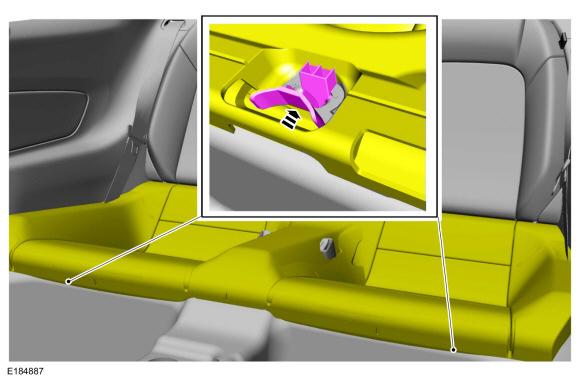
1 PLEASE READ ALL OF THE FOLLOWING INSTRUCTIONS CAREFULLY PRIOR TO INSTALLATION. AT ANY TIME YOU DO NOT UNDERSTAND THE INSTRUCTIONS Parts included: -GT350 Intake manifold M-944-M5 -GT350 Air bucket w/filter. Includes bucket to throttle body pipe -Air bucket inlet -GT350 Throttle body M-996-M5 -EVAP solenoid jumper harness -wire tie w/.5mm offset -Wire tie w/5mm offset -Foam seal -PCV tube, drivers side -Throttle body gasket -Brake booster vacuum line -Plug, sound symposer eliminator -ProCal voucher -Procal 3 vehicle interface connector -EO label -USB Cable -Bolts 6mm with stud, EVAP solenoid -Bolt 6mm PCV tube Warning: Read ProCal voucher before starting installation! Intake Manifold Removal NOTICE: During engine repair procedures, cleanliness is extremely important. Any foreign material, including any material created while cleaning gasket surfaces, that enters the oil passages, coolant passages, air intake ports or the oil pan, can cause engine failure. Release the fuel system pressure. Pressure release Fuel System Pressure Release NOTE: The FPDM are located on the LH side, beneath the rear seat cushion.

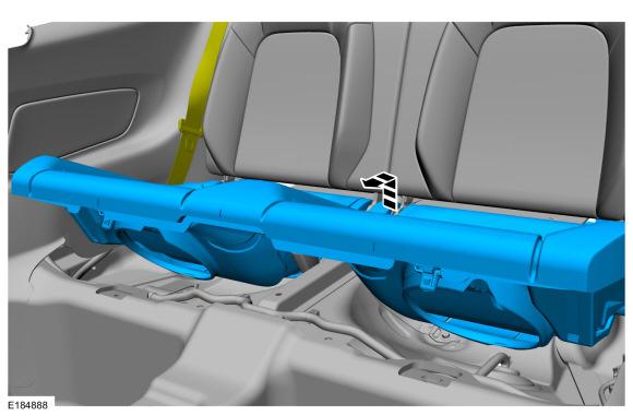
2 Remove the rear seat cushion. Rear Seat Cushion Removal On both sides. Move the front seats to the full forward position. NOTICE: The seat cushion tabs must be pressed in to release them from the floor. If the locking tabs are not pressed in, it may result in damage to the tabs. Located at the front of the seat cushion, press in on the locking tabs to release the seat cushion from the floor.
3

4 Disconnect the two Fuel Pump Control Module electrical connectors. Start the engine and allow it to idle until the engine stalls. Turn the ignition switch to the off position -Intake manifold removal continued- Disconnect the battery ground and positive cables. If equipped with a strut tower cross brace, detach the wiring harness retainer. Remove the nuts and the strut tower cross brace.


5 Remove engine appearance cover by pulling up on cover. Cover will not be reused with GT350 intake.

6 Air cleaner outlet pipe removal Disconnect and position aside the brake booster tubes, crankcase ventilation tube and resonator air inlet tube. Loosen the clamps and remove the air cleaner outlet pipe. Remove the nuts. Position the heater hose aside. Remove the heater hose support. -Intake manifold removal continued


7 Detach the vacuum tube retainer. Disconnect the vacuum tube from intake and brake booster. Release the clamps and remove the vacuum tube assembly. Disconnect the throttle body electrical connector.


8 Disconnect the couplings and remove the crankcase vent tube. Disconnect the EVAP purge valve electrical connector. Disconnect the EVAP tube and position aside. 3 Remove the nuts. Position the heater hose aside. Remove the heater hose support. 3

9 Remove the fuel rail insulators. Insulators will not be reused with GT350 intake. Disconnect the RH fuel injector electrical connectors.


10 Disconnect the LH fuel injector electrical connectors. Disconnect the fuel supply tube. Wrap rag around connector before removing to soak up any residual fuel. NOTE: It is not necessary to remove the fuel rail from the intake manifold assembly at this time.


11 Remove the fuel rail bolts. Loosen the intake manifold bolts. Position the manifold up and towards the front of the engine to access the rear of the manifold.


12 Disconnect the IMRC sensor electrical connectors at lower back of intake. Slide down locks and depress release tab. Detach the wire ties with offset at lower back of intake.


13 Remove the intake manifold. Disconnect the MAF sensor electrical connector. Detach and position the wire harness from the air cleaner. 3 Detach and position the sound symposer from the air cleaner. Remove the bolt and the air cleaner. Detach and remove the sound symposer tube from the air cleaner tube.


14 Use a trim panel removal tool or similar to release symposer tube from push pins. Release symposer tube from engine compartment bulkhead. Remove sound symposer tube from vehicle. Install symposer delete plug in engine compartment bulkhead.


15 GT 350 Intake manifold Installation Install new gaskets. Transfer fuel rail and injectors from GT intake it GT350 intake. Modify engine wiring harness. Un-tape and pull wire harness out of convoluted split loom.

16 Install convoluted loom (not included) over wires and re-taped. Release blue IMRC solenoid connector from tape. This allows the connector to reach the solenoid on the GT350 intake.

17 Install cable tie with 5mm off-set. RH side shown.

18 Install gray cable tie with.5mm off-set. LH side shown.


19 Verify gasket installation Position the intake manifold onto the engine. Attach the cable ties with off-set to intake
20 Plug in white electrical connectors into the IMRC sensors at back of intake. Push red tabs up to lock. Plug the blue electrical connectors into the IMRC solenoids.

21 Position the manifold to the installed position. Tighten the intake manifold bolts. Torque: Stage : 06 lb.in ( Nm) Stage : 35

 Stage : 90")
22 Install the fuel rail bolts. Torque: Stage : 89 lb.in (0 Nm) Stage : 90 Connect the fuel supply tube.
23 NOTE: On both sides. Connect the fuel injector electrical connectors. Remove the EVAP canister purge valve from the GT intake and install on GT350 intake. Use provided fasteners with stud. Both fasteners Torque: 89 lb.in (0 Nm) Remove the PCV tube from the GT intake and install on the GT350 intake. Use provided fastener. Torque: 89 lb.in (0 Nm)
24 Position the crankcase vent tube and connect the couplings. Install the heater hose support. Position the heater hose. Install the nuts. 3 Torque: 6 lb.in (7 Nm)

25 Connect the throttle body electrical connector Connect the EVAP tube. Modify the EVAP purge valve harness. Un-tape 90 degree from EVAP purge harness. Replace EVAP purge harness connector with connector provided.


26 Remove lock. Release pins one at a time and transfer to new connector. Remove pin lock from new connector.


27 Release pins one at a time from connector and insert in new connector. Make sure connector locks are positioned the same. When both pins are in place re-install pin lock removed in previous step. New jumper harness installed.

28 Install the brake booster vacuum tube assembly. 3

29 Install the heater hose support from GT intake. Install the nuts. 3 Torque: 6 lb.in (7 Nm) Position the heater hose.


30 Install the strut tower cross brace and nuts. Apply blue thread locking compound to nuts and Torque: 4 lb.ft (55 Nm) Attach the wiring harness retainer. Install GT350 throttle body Remove and re-use bolts from the Mustang GT throttle body. Install the Throttle Body (TB), then install and tighten the Throttle Body (TB) retaining bolts. Torque: Stage : 89 lb.in (0 Nm) Stage : 60

31 Modify air inlet rubber seal by making two cuts. Install air inlet on air cleaner assembly.

32 Install air cleaner assembly into vehicle. Angle air cleaner assembly with air inlet down. Rotate and push air cleaner assembly down. Reach into air inlet from filter side and make sure rubber flap is folded down while positioning air cleaner assembly. Install hose onto throttle body, do not tighten clamp. Install retaining bolt. Torque bolt to 89 lb. in

33 Route MAF harness as shown. Drill hole in Air filter bucket for existing wire tie on harness. Install wire tie with 5mm offset

34 Install foam seal.
 Connect the two Fuel Pump Control Module electrical")
35 Install supplied drivers side PCV tube. Tighten clamp. Torque: 44 lb.in (5 Nm) Connect the two Fuel Pump Control Module electrical connectors.
36 Install seat cushion. Connect battery cables Warning: calibration must be installed before driving Warning: Minimum 9 octane fuel required Start engine and check for leaks Shop for quality Ford Performance products on our website. On our website you can discover more about performance air intake systems.
NO PART OF THIS DOCUMENT MAY BE REPRODUCED WITHOUT PRIOR AGREEMENT AND WRITTEN PERMISSION OF FORD PERFORMANCE PARTS
 Please visit www. performanceparts.ford.com for the most current instruction and warranty information. PLEASE READ ALL OF THE FOLLOWING INSTRUCTIONS CAREFULLY PRIOR TO INSTALLATION. AT ANY TIME YOU DO
M-9424-M50B 2012 Boss 302 Intake Manifold INSTALLATION INSTRUCTIONS
 !!! PLEASE READ ALL OF THE FOLLOWING INSTRUCTIONS CAREFULLY PRIOR TO INSTALLATION. WARNING: CUSTOM CALIBRATION REQUIRED! CALIBRATION NOT INCLUDED! KIT CONTENTS: 1) Intake Manifold Assembly 2) Assembly
M-9424-M50CJ INTAKE MANIFOLD INSTALLATION INSTRUCTIONS
 Please visit www.fordracingparts.com for the most current instruction information!!! PLEASE READ ALL OF THE FOLLOWING INSTRUCTIONS CAREFULLY PRIOR TO INSTALLATION. AT ANY TIME YOU DO NOT UNDERSTAND THE
10/20/ Ford E 250 Engine Mechanical > Engine, 4.6L and 5.4L > IN VEHICLE REPAIR > Intake Manifold 5.4L
 2005 Ford E 250 : Engine Mechanical > Engine, 4.6L and 5.4L > IN VEHICLE REPAIR > Intake Manifold 5.4L Intake Manifold 5.4L Listen SECTION 303 01A: Engine 4.6L and 5.4L 2005 E Series Workshop Manual IN
IN-VEHICLE REPAIR. Upper Intake Manifold
 303-01-1 Engine 3.9L and 4.2L 303-01-1 IN-VEHICLE REPAIR Upper Intake Manifold Special Tool(s) Remover, Spark Plug Wire 303-106 (T74P-6666-A) Material Item Silicone Brake Caliper Grease and Dielectric
10/30/2018 Intake Manifold Replacement (RPOs LY2/LY6) 2007 GMC Truck Yukon Denali MotoLogic
 2007 GMC Truck Yukon Denali MotoLogic") 2007 Yukon Denali Applies to: 4.8L, 5.3L, 6.0L and 6.2L Report a problem with this article Removal Procedure 1. Remove the air cleaner outlet duct. Refer to Air Cleaner Resonator Outlet Duct Replacement.
2007 Yukon Denali Applies to: 4.8L, 5.3L, 6.0L and 6.2L Report a problem with this article Removal Procedure 1. Remove the air cleaner outlet duct. Refer to Air Cleaner Resonator Outlet Duct Replacement.
Intake Manifold Replacement
 Page 1 of 14 2004 Chevrolet TrailBlazer - 4WD Bravada, Envoy, Rainier, TrailBlazer (VIN S/T) Service Manual Engine Engine Mechanical - 4.8L, 5.3L, and 6.0L Repair Instructions - On Vehicle Document ID:
2001 Lincoln LS Workshop Manual
 Page 1 of 10 SECTION 303-01B: Engine 3.9L 2001 Lincoln LS Workshop Manual IN-VEHICLE REPAIR Procedure revision date: 05/16/2000 Intake Manifold Removal 1. Disconnect the battery ground cable. For additional
Intake Manifold Replacement
 Document ID# 738735 2002 Chevrolet Chevy Suburban - 4WD Print Intake Manifold Replacement Removal Procedure Important: The intake manifold, throttle body, fuel rail, and injectors may
ALLDATA Online Chevy Truck S10/T10 Blazer 2WD V6-4.3L VIN W - Intake... Intake Manifold Replacement (Upper)
") ALLDATA Online - 2001 Chevy Truck S10/T10 Blazer 2WD V6-4.3L VIN W - Intake... Page 1 of 21 Home Account Contact ALLDATA Log Out Help PAUL REDEHOFT Select Vehicle New TSBs Technician's Reference Component
ALLDATA Online - 2001 Chevy Truck S10/T10 Blazer 2WD V6-4.3L VIN W - Intake... Page 1 of 21 Home Account Contact ALLDATA Log Out Help PAUL REDEHOFT Select Vehicle New TSBs Technician's Reference Component
Lower Intake Manifold Replacement
 Lower Intake Manifold Replacement Removal Procedure 1. Turn OFF all the lamps and the accessories. 2. Ensure the ignition switch is in the OFF position. 3. Disconnect the negative battery cable from the
 Page 1 of 6 Section 03-01C: Engine 3.4L SHO 1999 Taurus/Sable Workshop Manual IN-VEHICLE SERVICE Procedure revision date: 06/25/1998 Intake Manifold Upper Removal 1. Disconnect battery ground cable (14301).
Audi > B4 > Liter V6 2V Engine Mechanical, Engine Code(s): AAH, AFC 10 Engine Assembly
: AAH, AFC 10 Engine Assembly") Audi > B4 > 1993 1995 2.8 Liter V6 2V Engine Mechanical, Engine Code(s): AAH, AFC 10 Engine Assembly Removing The engine is removed from above, after being separated from the transmission. Note: All tie
Audi > B4 > 1993 1995 2.8 Liter V6 2V Engine Mechanical, Engine Code(s): AAH, AFC 10 Engine Assembly Removing The engine is removed from above, after being separated from the transmission. Note: All tie
1. With the vehicle in NEUTRAL, position it on a hoist. For additional information, refer to Section
 SECTION 303-01C: Engine 5.4L (4V) 2009 Mustang Workshop Manual REMOVAL Procedure revision date: 07/25/2008 Engine Special Tool(s) Heavy Duty Floor Crane 014-00071 or equivalent Lifting Bracket, Engine
2011 Mercury Grand Marquis LS
 Fig. 6: Locating Intake Manifold Crash Bracket With Tie Strap 24. Remove the intake manifold crash bracket bolt. 25. Disconnect the fuel rail pressure and temperature sensor vacuum and electrical connectors.
Zoom and Print Options
 Vehicle» Engine, Cooling and Exhaust» Engine» Service and Repair» Removal and Replacement» Engine Replacement Engine Replacement ^ Tools Required - J 38185 Hose Clamp Pliers Removal Procedure 1. Remove
Ford Racing Laser Etched Valve Covers (05-10 GT, GT500)
") Applicable Part Numbers: M-6582-FR3VBL (Blue) M-6582-FR3VBLK (Black) M-6582-C543V (Chrome) List of Tools: 1/4 ratchet 3/8 ratchet 8mm socket 10mm socket 7mm socket 1/4 & 3/8 extensions Plastic gasket scraper
Applicable Part Numbers: M-6582-FR3VBL (Blue) M-6582-FR3VBLK (Black) M-6582-C543V (Chrome) List of Tools: 1/4 ratchet 3/8 ratchet 8mm socket 10mm socket 7mm socket 1/4 & 3/8 extensions Plastic gasket scraper
1501 Industrial Way N., Toms River, NJ Fax: PACKING LIST
 1/6/04 1501 Industrial Way N., Toms River, NJ 08755 732-349-2109 Fax:732-244-0867 MODERATE - Installation requires metric tools and possibly cutting and drilling. The ability to closely follow instructions
ALLDATA Online Chevy Truck S10/T10 P/U 2WD L4-2.2L VIN 4 - Service and... Page 1 of 12. Service and Repair
 ALLDATA Online - 2000 Chevy Truck S10/T10 P/U 2WD L4-2.2L VIN 4 - Service and... Page 1 of 12 Home Account Contact ALLDATA Log Out Help PAUL REDEHOFT Select Vehicle New TSBs Technician's Reference Component
1998 F-150/250 Workshop Manual
 Page 1 of 13 SECTION 303-01B: Engine 4.6L and 5.4L 1998 F-150/250 Workshop Manual IN-VEHICLE REPAIR Procedure revision date: 03/07/2000 Intake Manifold Removal WARNING: Do not smoke or carry lighted tobacco
STARTER COMPONENTS FOR REMOVAL AND INSTALLATION
 Removal STARTER COMPONENTS FOR REMOVAL AND INSTALLATION Starter Components For Removal And Installation REMOVAL OF STARTER 1. DISCONNECT CABLE FROM NEGATIVE TERMINAL OF BATTERY CAUTION: Work must be started
L Mustang Supercharger Kit
 2015-2017 5.0L Mustang Supercharger Kit Installation Instructions P/N: M-6066-M8627 EO D-418-27 Application: 2015-2017 Ford Mustang GT with 5.0L 4-Valve Engine w/ Manual Transmission Important Notes: Before
Zoom and Print Options
 Vehicle» Engine, Cooling and Exhaust» Engine» Cylinder Head Assembly» Valve Cover» Service and Repair» Procedures» LH Valve Cover LH Removal 1. Disconnect the battery ground cable. 2. Remove the air cleaner
Installation Instructions for: TOYOTA 4.5L SUPERCHARGER SYSTEM
 Installation Instructions for: TOYOTA 4.5L SUPERCHARGER SYSTEM 1995-1997 Land Cruiser * PREMIUM FUEL REQUIRED * Magnuson Products LLC 1990 Knoll Drive, Bldg A, Ventura, CA 93003 (805) 642-8833 phone *
IN-VEHICLE SERVICING > VALVE COVER - RH
 Page 1 of 20 Service Manual: ENGINE - 5.4L (3V)- F-150 & MARK LT IN-VEHICLE SERVICING > VALVE COVER - RH 2008 Ford Pickup 5.4L Eng F150 Material Item Specification Motorcraft Metal Surface Prep ZC-31 PAG
1999 E-Series Workshop Manual
 http://www.fordservicecontent.com/pubs/content/~wsxm/~mus~len/21/sxm31c16.h... Page 1 of 3 SECTION 303-01C: Engine 6.8L 1999 E-Series Workshop Manual IN-VEHICLE REPAIR Procedure revision date: 06/30/1998
Installation Instructions
 Ford F-650 Chassis Cab Liquid Propane Autogas Fuel System Dual and Single Tanks Revision History -AA Initial Release 10/2013 -AB SRM Isolator Delete 11/2014 -BA Add Single Tank Configuration 02/2015 Installation
INTAKE MANIFOLD INSPECTION/REPLACEMENT
 ATTACHMENT III Owner Notification Program 99M01 INTAKE MANIFOLD INSPECTION/REPLACEMENT AFFECTED VEHICLES: 1997 AND 1998 CROWN VICTORIA POLICE INTERCEPTOR VEHICLES WITH 4.6L SOHC ENGINES BUILT AT THE ST.
Intake Manifold Replacement
 Page 1 of 13 Your Current Vehicle: 2008 Cadillac STS Intake Manifold Replacement Intake Manifold Replacement Removal Procedure 1. Turn the ignition OFF. 2. Remove the fuel injector sight shield. Refer
2011 Transit Connect Workshop Manual
 SECTION 303-12: Intake Air Distribution and Filtering REMOVAL AND INSTALLATION Procedure revision date: 09/23/2010 Intake Air System Components - Exploded View Item Part Number 1 9F991 Throttle Body (TB)
Disconnect the breather tube from the air cleaner outlet duct.
 Disconnect the breather tube from the air cleaner outlet duct. Disconnect the IAT sensor harness connector. Remove the air cleaner outlet duct retaining wingnut. Separate the air cleaner outlet duct from
INSTALLATION INSTRUCTIONS CATCH CAN KIT
 INSTALLATION INSTRUCTIONS CATCH CAN KIT FORD FOCUS Document: 19-0150 Support: info@radiumauto.com STEPS 1 TO 19 COVER THE PCV SIDE CATCH CAN KIT (P/N: 20-0315) STEPS 20-32 COVER THE CRANKCASE CATCH CAN
2003 RSX - Intake Manifold Removal and Installation
 2003 RSX - Intake Manifold Removal and Installation Exploded View - K20A3 Engine Removal - K20A3 Engine 1. Remove the intake manifold cover. 2. Disconnect the intake air temperature (IAT) sensor connector
DISASSEMBLY. Engine. CAUTION: Remove the cylinder heads before removing the crankshaft. Failure to do so can result in engine damage.
 303-01A-1 DISASSEMBLY Engine Special Tool(s) Remover, Crankshaft Vibration Damper 303-101 (T74P-3616-A) Special Tool(s) Crankshaft Socket 303-674 303-01A-1 Remover, Crankshaft Vibration Damper 303-773
Edelbrock Victor II Intake Manifold. For Chrysler 5.7L (Eagle) and 6.1L Gen III HEMI Engines Part #7179
 and 6.1L Gen III HEMI Engines Part #7179") For Chrysler 5.7L (Eagle) and 6.1L Gen III HEMI Engines PLEASE study these instructions carefully before beginning this installation. You should be familiar with and comfortable working on your vehicle.
For Chrysler 5.7L (Eagle) and 6.1L Gen III HEMI Engines PLEASE study these instructions carefully before beginning this installation. You should be familiar with and comfortable working on your vehicle.
M-9603-GTB 85 mm Cold Air Kit w/premium Cal. for 4.6L 3V V8 Mustang INSTALLATION INSTRUCTIONS
 Please contact the Techline for the most current instruction information 800-367-3788.!!! PLEASE READ THE FOLLOWING INSTRUCTIONS CAREFULLY PRIOR TO INSTALLATION!!! OVERVIEW: This kit is designed for use
REMOVAL. Fig Sized for Print
 ALLDATA Online - 2000 Dodge Truck Grand Caravan FWD V6-3.3L VIN R - Intake M... Page 1 of 10 REMOVAL 1. Remove windshield wiper module. 2. Perform fuel system pressure release procedure (before attempting
INSTALLATION INSTRUCTIONS CATCH CAN KIT
 INSTALLATION INSTRUCTIONS CATCH CAN KIT FORD FOCUS Document: 19-0150 Support: info@radiumauto.com STEPS 1 TO 19 COVER THE PCV CATCH CAN KIT (P/N: 20-0315) STEPS 20-32 COVER THE CRANKCASE CATCH CAN KIT
1 of 12 10/5/2015 8:11 AM
 1 of 12 10/5/2015 8:11 AM REMOVAL 1. Perform the fuel pressure release procedure See: Fuel Pressure Release > Procedures > Fuel System Pressure Release Procedure. 2. Recover the refrigerant from the refrigerant
REMOVAL. Cylinder Head. All cylinder heads. 1. Remove the engine. For additional information, refer to Engine in this section.
 303-01B-1 303-01B-1 REMOVAL Cylinder Head Material Item Specification Special Tool(s) Motorcraft Metal Surface Prep Modular Engine Lift Bracket ZC-31 303-F047 (014-00073) or equivalent Silicone Gasket
INSTALLATION INSTRUCTIONS CATCH CAN KIT
 INSTALLATION INSTRUCTIONS CATCH CAN KIT FORD FOCUS Document: 19-0150 Support: info@radiumauto.com STEPS 1-19 COVER THE PCV SIDE CATCH CAN KIT (P/N: 20-0315) STEPS 20-32 COVER THE CRANKCASE CATCH CAN KIT
Procharger Stage II Intercooled Supercharger System (11-14 GT)
") Procharger Stage II Intercooled Supercharger System (11-14 GT) Installation Time: Approximately one day. Installed on 2012 Mustang GT 5.0/Manual Required Tools 3/8 Socket Set (Standard and Metric) 1/2
Procharger Stage II Intercooled Supercharger System (11-14 GT) Installation Time: Approximately one day. Installed on 2012 Mustang GT 5.0/Manual Required Tools 3/8 Socket Set (Standard and Metric) 1/2
FREE $15 Gift Card for every $100 spent on Ship To Home orders. Find Out How
 1 of 29 10/12/2011 5:05 PM FREE $15 Gift Card for every $100 spent on Ship To Home orders. Find Out How Ford Ranger/Explorer/Mountaineer 1991-1999 Intake Manifold REMOVAL & INSTALLATION Print The engines
INTAKE MANIFOLD COLLECTOR. 1. Electric throttle control actuator 2. Gasket 3. Vacuum hose
 INTAKE MANIFOLD COLLECTOR Removal and Installation PFP:14003 ABS0095V 1. Electric throttle control actuator 2. Gasket 3. Vacuum hose 4. EVAP canister purge volume control solenoid valve 5. Bracket 6. Intake
DISASSEMBLY. Engine. Special Tool(s) Locking Tool, Camshaft Phaser Sprocket Special Tool(s)
 Locking Tool, Camshaft Phaser Sprocket Special Tool(s)") 303-01B-1 DISASSEMBLY Engine Special Tool(s) Remover, Crankshaft Rear Slinger 303-514 (T95P-6701-AH) Special Tool(s) 303-01B-1 Locking Tool, Camshaft Phaser Sprocket 303-1046 Remover, Crankshaft Rear Seal
303-01B-1 DISASSEMBLY Engine Special Tool(s) Remover, Crankshaft Rear Slinger 303-514 (T95P-6701-AH) Special Tool(s) 303-01B-1 Locking Tool, Camshaft Phaser Sprocket 303-1046 Remover, Crankshaft Rear Seal
9/20/2017 Automatic Transaxle/Transmission External Controls - Selector Lever Cable - Removal and Installation 2008 Ford Edge MotoLogic
 2008 Edge SECTION 307-05: Automatic Transaxle/Transmission External Controls REMOVAL AND INSTALLATION 2008 Edge/MKX Workshop Manual Procedure revision date: 06/17/2009 Report a problem with this article
Edelbrock Victor II Intake Manifold. For Chrysler 5.7L (Eagle), 6.1L and 6.4L Gen III HEMI Engines Part #7179
, 6.1L and 6.4L Gen III HEMI Engines Part #7179") For Chrysler 5.7L (Eagle), 6.1L and 6.4L Gen III HEMI Engines PLEASE study these instructions carefully before beginning this installation. You should be familiar with and comfortable working on your
For Chrysler 5.7L (Eagle), 6.1L and 6.4L Gen III HEMI Engines PLEASE study these instructions carefully before beginning this installation. You should be familiar with and comfortable working on your
L Mustang Phase 1 ROUSHcharger Kit Installation Instructions P/N: (R1315-P1CAL) EO D (EO not applicable with MY2016)
 EO D (EO not applicable with MY2016)") 2015-2016 5.0L Mustang Phase 1 ROUSHcharger Kit Installation Instructions P/N: 421823 (R1315-P1CAL) EO D-418-25 (EO not applicable with MY2016) 39555 Schoolcraft Rd, Plymouth MI, 48170 800.59.ROUSH 2015
2015-2016 5.0L Mustang Phase 1 ROUSHcharger Kit Installation Instructions P/N: 421823 (R1315-P1CAL) EO D-418-25 (EO not applicable with MY2016) 39555 Schoolcraft Rd, Plymouth MI, 48170 800.59.ROUSH 2015
Installation Instructions
 2011+ Mustang GT Supercharger Kit(s) P/Ns: M-6066-MGT525D M-6066-MGT525PD M-6066-MGT624D M-6066-MGT624PD Installation Instructions Application: 2011+ Ford Mustang GT with 5.0L 4-Valve Engines w/ Manual
7. Remove the starter motor. Refer to Starter Motor Replacement (2.2L) or Starter Motor Replacement (4.3L).
 or Starter Motor Replacement (4.3L).") 1 of 9 1/5/2013 6:40 PM Removal Procedure 1. Disconnect the battery negative cable. Refer to Battery Replacement. 2. Remove the hood. Refer to Hood Replacement. 3. If the vehicle is equipped with a manual
1 of 9 1/5/2013 6:40 PM Removal Procedure 1. Disconnect the battery negative cable. Refer to Battery Replacement. 2. Remove the hood. Refer to Hood Replacement. 3. If the vehicle is equipped with a manual
COMPONENT LOCATOR > DISASSEMBLED VIEWS
 Page 1 of 45 2006 Pontiac Grand Prix 3.8L Eng Base Service Manual: ENGINE MECHANICAL - 3.8L COMPONENT LOCATOR > DISASSEMBLED VIEWS Fig 1: Engine Block Component Views Callout Component Name 100 Engine
8 Zip Tie Zip Tie 1 Union Fitting 1 ½ ½ Union Reducer Fitting Union 1 5/8 ½ (For Plastic Intake Manifold Vehicles)
") P IAG Street Series Air / Oil Separator (AOS) For 2017 STI Part# IAG-ENG-7151 Tools Required: Ratchet, torque wrench, extensions, needle nose pliers, hose cutter, snips/scissors, flat head screw driver,
P IAG Street Series Air / Oil Separator (AOS) For 2017 STI Part# IAG-ENG-7151 Tools Required: Ratchet, torque wrench, extensions, needle nose pliers, hose cutter, snips/scissors, flat head screw driver,
1988 Ford F-350 PICKUP
 1988 Ford F-350 PICKUP Submodel: Engine Type: V8 Liters: 7.5 Fuel Delivery: FI Fuel: GAS 1987 93 4.9L Engine The intake and exhaust manifolds on these engines are known as combination manifolds and are
Disconnect negative battery cable and remove coolant bottle cap.
 1 of 16 3/25/2012 10:18 AM ools Required SA9105E 3-Bar Engine Support Fixture SA9412G Constant Force Clamp Pliers SA9127E Gage Bar Set Powertrain Assembly Removal Caution: Do not allow smoking or the use
2000 Chrysler SEBRING
 2000 Chrysler SEBRING Submodel: JX Engine Type: V6 Liters: 2.5 Fuel Delivery: FI Fuel: GAS 2.0L SOHC and 2.4L DOHC Engines The intake manifold for the 2.0L SOHC engine is a long branch design made of a
3.4L V6 SUPERCHARGER 7 TH INJECTOR KIT
 Part Number: 00602-17620-260 00602-17620-261 00602-17620-263 00602-17620-264 00602-17620-274 00602-17620-275 00602-17620-276 Section I Installation Preparation Kit Contents Item # Quantity Reqd. Description
REMOVAL & INSTALLATION
 REMOVAL & INSTALLATION NOTE: For reassembly reference, label all electrical connectors, vacuum hoses and fuel lines before removal. Also place mating marks on engine hood and other major assemblies before
Ford 6.0L. Part #: Part #: BD GASKET PART# will be needed for this installation.
 1 BD EGR COOLER 2003-2007 Ford 6.0L Part #: 1090201 Part #: 1090202 PLEASE READ ALL INSTRUCTIONS BEFORE INSTALLATION BD GASKET PART# 1090002 will be needed for this installation. 2 K I T C O N T E N T
Valve Cover - RH Material
 1 of 5 5/15/2015 8:06 AM Valve Cover - RH Material 2 of 5 5/15/2015 8:06 AM 3 of 5 5/15/2015 8:06 AM Removal CAUTION: During engine repair procedures, cleanliness is extremely important. Any foreign material,
2. Disconnect the accelerator control cable and the cruise control cable from the throttle body. 3. Disconnect the vacuum hose from the throttle body.
 2002 Silverado K 4WD Applies to: 4.8L, 5.3L, and 6.0L Report a problem with this article Removal Procedure 1. Remove the air intake duct. Refer to Air Cleaner Resonator Outlet Duct Replacement. 2. Disconnect
M-6066-SGT (Black)/M-6066-SGTP (Polished) SVT Mustang Supercharger Upgrade Kit INSTALLATION INSTRUCTIONS
/M-6066-SGTP (Polished) SVT Mustang Supercharger Upgrade Kit INSTALLATION INSTRUCTIONS") Please contact the Techline for the most current instruction information (800) FORD788.!!! PLEASE READ THE FOLLOWING INSTRUCTIONS CAREFULLY PRIOR TO INSTALLATION!!! OVERVIEW: This kit is designed for use
Please contact the Techline for the most current instruction information (800) FORD788.!!! PLEASE READ THE FOLLOWING INSTRUCTIONS CAREFULLY PRIOR TO INSTALLATION!!! OVERVIEW: This kit is designed for use
IAG Competition Series Air / Oil Separator (AOS) For 2017 STI
 For 2017 STI") P IAG Competition Series Air / Oil Separator (AOS) For 2017 STI Part# IAG-ENG-7251 Tools Required: Ratchet, torque wrench, extensions, needle nose pliers, hose cutter, snips/scissors, flat head screw driver,
P IAG Competition Series Air / Oil Separator (AOS) For 2017 STI Part# IAG-ENG-7251 Tools Required: Ratchet, torque wrench, extensions, needle nose pliers, hose cutter, snips/scissors, flat head screw driver,
Zoom and Print Options
 Vehicle» Engine, Cooling and Exhaust» Engine» Cylinder Head Assembly» Valve Cover» Service and Repair» Procedures» RH Valve Cover RH Removal 1. Disconnect the battery ground cable. 2. Remove the air cleaner
Installation Instructions General Motors 8.1 Sequential Vapor Injection (S.V.I.) System 7500/6500 Series Trucks model year.
 System 7500/6500 Series Trucks model year.") Installation Instructions General Motors 8.1 Sequential Vapor Injection (S.V.I.) System 7500/6500 Series Trucks 2003-2005 model year. Technocarb Equipment (2004) Ltd. 4-30435 Progressive Way Abbotsford,
Installation Instructions General Motors 8.1 Sequential Vapor Injection (S.V.I.) System 7500/6500 Series Trucks 2003-2005 model year. Technocarb Equipment (2004) Ltd. 4-30435 Progressive Way Abbotsford,
Cylinder head, removing and
 Page 1 of 35 15-2 Cylinder head, removing and installing Note: Replace cylinder head bolts. Always replace self-locking nuts, bolts as well as gaskets and O-rings. After installing a replacement cylinder
2002 Mustang Workshop Manual
 Page 1 of 13 SECTION 303-01B: Engine 4.6L (2V) 2002 Mustang Workshop Manual REMOVAL Procedure revision date: 01/02/2003 Cylinder Heads Special Tool(s) Remover, Crankshaft Vibration Damper 303-009 (T58P-6316-D)
2006 Honda Civic SI Supercharger Kit Installation Instruction Kit #
 2006 Honda Civic SI Supercharger Kit Installation Instruction Kit #350-091 3239 MONIER CIRCLE, STE.5 RANCHO CORDOVA, CA 95742 916.635.4550 FAX 916.635.4632 www.ct-engineering.com INS-157 VERSION: 3.25.2009
2014+ Ram 3.0 EcoDiesel EGR Delete
 2014+ Ram 3.0 EcoDiesel EGR Delete Installation Guide WARNING: This product is for competition use only in a sanctioned racing event. NOT FOR USE ON VEHICLES USED OR REGISTERED FOR USE ON A PUBLIC ROAD
Ford F L PHASE 2 ROUSHcharger Kit
 2011-2014 Ford F-150 6.2L PHASE 2 ROUSHcharger Kit P/N: 421432 (1162-P2CAL) EO # D-418-23 Installation Instructions Application: 2011-2014 Ford F-150 with 6.2L 2-Valve Engine w/ Automatic Transmission.
Disconnect the APP sensor harness connector. See Fig. 4. Remove the accelerator pedal mounting nuts. Remove the APP assembly.
 ENGINE CONTROLS - REMOVAL, OVERHAUL & INSTALLATION - 6.6L DIESEL... Page 1 of 41 FUEL SYSTEMS ACCELERATOR PEDAL POSITION SENSOR Removal & Installation Disconnect the APP sensor harness connector. See Fig.
2002 Crown Victoria/Grand Marquis Workshop Manual
 Page 1 of 9 SECTION 303-04: Fuel Charging and Controls 2002 Crown Victoria/Grand Marquis Workshop Manual REMOVAL AND INSTALLATION Procedure revision date: 06/13/2001 Fuel Injection Supply Manifold Material
ENGINE ASSEMBLY STOCK TO 250 HP
 GM SPORT COMPACT Performance Build Book 25 ENGINE ASSEMBLY STOCK TO 250 HP Fig. 3 The stock ECOTEC engine has proven reliable to 250 hp.(fig. 3) Performance upgrades are available from GM Performance Parts
Installation Instructions for: Radix. INTERCOOLED SUPERCHARGER SYSTEM 2008 Hummer H3-Alpha
 Installation Instructions for: Radix INTERCOOLED SUPERCHARGER SYSTEM 2008 Hummer H3-Alpha Step-by-step instructions for installing the best in supercharger systems. ATTENTION! Your MAGNA CHARGER intercooler
M-9603-CJ 123 mm Cold Air Kit for 5.4L 4V V8 Cobra Jet Mustang INSTALLATION INSTRUCTIONS
 Please contact the Techline for the most current instruction information 1-800-367-3788.!!! PLEASE READ THE FOLLOWING INSTRUCTIONS CAREFULLY PRIOR TO INSTALLATION!!! OVERVIEW: This kit is designed for
ADM Performance 6079 Mapleshade Lane Dallas, Texas (214)
") 1) Disconnect Battery Ground 2) Raise front end of Vehicle FAN INSTALL INSTRUCTIONS 3) Remove lower Radiator hose and drain coolant into a pan. (you will reuse coolant later) 4) Remove Air Intake piping
1) Disconnect Battery Ground 2) Raise front end of Vehicle FAN INSTALL INSTRUCTIONS 3) Remove lower Radiator hose and drain coolant into a pan. (you will reuse coolant later) 4) Remove Air Intake piping
Intake Manifold Replacement
 ALLDATA Online - 2001 Cadillac DeVille V8-4.6L VIN 9 - Intake Manifold Replacement Page 1 of 15 Home Account Contact ALLDATA Log Out Help DAN GRIMWOOD DAN GRIMWOOD00002 Select Vehicle New TSBs Technician's
READ THIS IMPORTANT NOTICE BEFORE INSTALLING THE TRD SUPERCHARGER SYSTEM.
 Preparation READ THIS IMPORTANT NOTICE BEFORE INSTALLING THE TRD SUPERCHARGER SYSTEM. The TRD Supercharger System requires a special calibration that needs to be installed into the OEM ECU. The supercharger
1997 Volvo 850 GLT. Fig. 2: Removing Drive Shaft, Engine Mount Bolt & Torque Arm (5-Cylinder) Courtesy of VOLVO CARS OF NORTH AMERICA.
 Courtesy of VOLVO CARS OF NORTH AMERICA.") Fig. 2: Removing Drive Shaft, Engine Mount Bolt & Torque Arm (5-Cylinder) 4. Remove front exhaust pipe nuts and springs. Remove front exhaust pipe bolts. Disconnect speedometer. Remove engine mounting
Fig. 2: Removing Drive Shaft, Engine Mount Bolt & Torque Arm (5-Cylinder) 4. Remove front exhaust pipe nuts and springs. Remove front exhaust pipe bolts. Disconnect speedometer. Remove engine mounting
INSTALLATION INSTRUCTIONS CATCH CAN KIT MITSUBISHI EVOLUTION X Document# Customer Support:
 The EVOX catch can kit is available in 3 variations. The PCV kit installs between the PCV valve and the intake manifold. The crankcase kit installs between the valve cover vent port and the pre-turbo air
2013 Mustang Workshop Manual
 32. Attach the wiring harness retainers to the LH side of the oil pan and the front oil pan stud bolts and install the 2 nuts. Tighten to 8 Nm (71 lb-in). 33. Position the underbody shield and install
APR, LLC
 + 1. 3 3 4. 5 0 2. 5 1 8 1 4 8 0 0 U S H W Y 2 8 0 W e s t, O p e l i k a, A l a b a m a 3 6 8 0 1 4 8 0 0 U S H W Y 2 8 0 W e s t, O p e l i k a, A l a b a m a 3 6 8 0 1 + 1. 3 3 4. 5 0 2. 5 1 8 1 NOTES:
Cylinder Head. Special Tool(s) 3-Jaw Puller 303-D121 or equivalent. Compressor, Valve Spring
 3-Jaw Puller 303-D121 or equivalent. Compressor, Valve Spring") SECTION 303-01B: Engine 4.6L (3V) 2009 Mustang Workshop Manual REMOVAL Procedure revision date: 03/15/2009 Cylinder Head Special Tool(s) 3-Jaw Puller 303-D121 or equivalent Compressor, Valve Spring 303-1039
SECTION 303-01B: Engine 4.6L (3V) 2009 Mustang Workshop Manual REMOVAL Procedure revision date: 03/15/2009 Cylinder Head Special Tool(s) 3-Jaw Puller 303-D121 or equivalent Compressor, Valve Spring 303-1039
303-01C Engine 3.5L 2010 Fusion, Milan, MKZ, Fusion Hybrid, Milan Hybrid. REMOVAL Procedure revision date: 10/19/2012. Engine
 2010 MKZ Report a problem with this article 303-01C Engine 3.5L 2010 Fusion, Milan, MKZ, Fusion Hybrid, Milan Hybrid REMOVAL Procedure revision date: 10/19/2012 Engine Special Tool(s) 2,200# Floor Crane,
LChevrolet Camaro Supercharger Kit
 PART #92000A Important Notes: 2010-2013 6.2LChevrolet Camaro Supercharger Kit The use of fuel additives (ie. octane boosters) is not recommended. There is a possibility that these chemicals can damage
REPAIR INSTRUCTIONS ON-VEHICLE SERVICE
 1G-6 REPAIR INSTRUCTIONS ON-VEHICLE SERVICE AIR CLEANER AND INTAKE AIR DUCT Cover Element Housing Specifications Element Type Service Interval Dry-Element Type * Initial cleaning: 5,000 km, Clean or change
1999 F-150/250 Workshop Manual
 Page 1 of 8 SECTION 303-01B: Engine 4.6L and 5.4L IN-VEHICLE REPAIR Procedure revision date: 02/03/1999 Intake Manifold Lightning Removal WARNING: Do not smoke or carry lighted tobacco or open flame of
INTERCOOLED SUPERCHARGER SYSTEM FORD 5.4L 3V F-150 TRUCK
 Installation Instructions for: INTERCOOLED SUPERCHARGER SYSTEM 2004-2006 FORD 5.4L 3V F-150 TRUCK Step-by-step instructions for installing the best in supercharger systems. 89-89-65-001 Rev C Magnuson
Fastener Tightening Specifications Specification
 2008 G6 Applies to: 3.5L Report a problem with this article Fastener Tightening s A/C Compressor Bracket Bolt Camshaft Position Actuator Assembly Bolt 16 Y 12 lb ft Camshaft Position Actuator Magnet Bolt
2. Remove the intake manifold cover. Refer to Intake Manifold Cover Replacement.
 VALVE COVER GASKET Valve Rocker Arm Cover Replacement - Left Side Removal Procedure 1. Partially drain the cooling system. Refer to Cooling System Draining and Filling (LZE, LZ4, LZG, 9C1, 9C3, GE47716
2007 Escape/Mariner/Escape Hybrid/Mariner Hybrid Workshop Manual
 SECTION 303-08A: Engine Emission 2007 Escape/Mariner/Escape Hybrid/Mariner Hybrid Control 2.3L Positive Crankcase Ventilation (PCV) System Components Exploded View View (157 KB) Printable Item Part Number
REMOVAL AND INSTALLATION
 501-12-1 Instrument Panel and Console 501-12-1 REMOVAL AND INSTALLATION Instrument Panel Removal CAUTION: Electronic modules are sensitive to static electrical charges. If exposed to these charges, damage
Turner M50 Manifold Adapter Install. April 26, 2012
 April 26, 2012 Models: 1996-99 E36 328i/M3; 1997-98 E39 528i, 1997-98 Z3 2.8, 1998-2000 MZ3 S52 Product(s): Turner M50 Manifold Adapter Kit Subject: Installation Guidelines and Tips This guide will aid
Intake Components 1117
 Item Part Number Description 1 W705654 Bolt 2 N807309 Bolt (2 req'd) 3 9F460 Bracket 4 N807071 Bolt (5 req'd) 5 9A448 Intake manifold (upper) 6 9E498 Vacuum harness 7 9F792 Fuel injection supply manifold
INTAKE (INDUCTION) IN(TURBO)
 IN(TURBO)") IN(TURBO) Page 1. General Description...2 2. Air Cleaner...7 3. Air Intake Duct...8 4. Intake Duct...9 5. Intercooler...10 6. Turbocharger...12 7. Air By-pass Valve...14 8. Resonator Chamber...15 GENERAL
IN(TURBO) Page 1. General Description...2 2. Air Cleaner...7 3. Air Intake Duct...8 4. Intake Duct...9 5. Intercooler...10 6. Turbocharger...12 7. Air By-pass Valve...14 8. Resonator Chamber...15 GENERAL
2009 PCED Gasoline Engines SECTION 1: Description and Operation. Intake Air System
 2009 PCED Gasoline Engines SECTION 1: Description and Operation Procedure revision date: 05/27/2010 Overview Intake Air Systems The intake air system provides clean air to the engine, optimizes air flow,
2000 Econoline Workshop Manual. 3. Install the upper intake manifold. 2. NOTE: Tighten the bolts in two stages.
 2. NOTE: Tighten the bolts in two stages. Tighten the bolts in the sequence shown. Stage 1: Tighten to 2 Nm (18 lb-in). Stage 2: Tighten to 10 Nm (89 lb-in). 3. Install the upper intake manifold. Position
Engine and A4LDE Automatic Transmission Remove and Install ( ) Remove
 Remove") Engine and A4LDE Automatic Transmission Remove and Install ( 3 0) Special Tools 068A -068A Engine lifting bracket -540 Bolt tightening angle gauge Workshop Equipment Transmission jack Workshop crane Assembly
Engine and A4LDE Automatic Transmission Remove and Install ( 3 0) Special Tools 068A -068A Engine lifting bracket -540 Bolt tightening angle gauge Workshop Equipment Transmission jack Workshop crane Assembly
Huron Speed Products Twin Turbo Install Gen 2 CTS-V (09-15)
") Huron Speed Products Twin Turbo Install Gen 2 CTS-V (09-15) The following install guide is simply that, a guide to help you with installation. It is by no means the exact method to perform installation,
Huron Speed Products Twin Turbo Install Gen 2 CTS-V (09-15) The following install guide is simply that, a guide to help you with installation. It is by no means the exact method to perform installation,
ENGINE AND EMISSION CONTROL
 17-1 GROUP 17 ENGINE AND EMISSION CONTROL CONTENTS ENGINE CONTROL........... 17-3 GENERAL INFORMATION....... 17-3 SERVICE SPECIFICATIONS..... 17-3 ON-VEHICLE SERVICE.......... 17-3 ACCELERATOR CABLE CHECK
M-9603-SVT mm Cold Air Kit w/premium Calibration INSTALLATION INSTRUCTIONS
 Please visit www.fordracingparts.com for the most current instruction information!!! PLEASE READ ALL OF THE FOLLOWING INSTRUCTIONS CAREFULLY PRIOR TO INSTALLATION. AT ANY TIME YOU DO NOT UNDERSTAND THE