400 VMC Series. Compressor Manual Models: 440, 450, 450XL, and 460. Manufacturers of Industrial Refrigeration and Gas Compression Equipment
|
|
|
- Clementine Norris
- 6 years ago
- Views:
Transcription


1 Manufacturers of Industrial Refrigeration and Gas Compression Equipment 400 VMC Series Compressor Manual Models: 440, 450, 450XL, and 460 VPN 35391B June 2003 Rev_00 Price$60.00
2
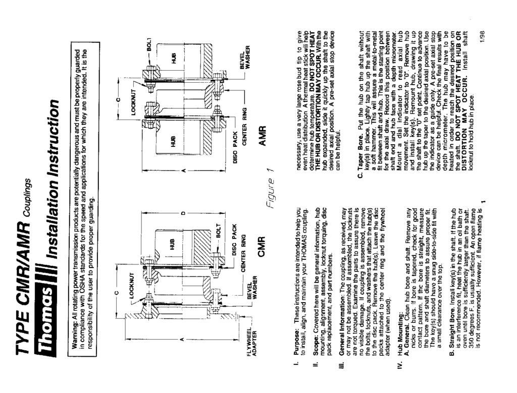
3 VILTER MANUFACTURING CORPORATION VILTER Multicylinder Compressor OPERATING INSTRUCTION MANUAL 400 SERIES COMPRESSORS READ CAREFULLY BEFORE INSTALLING AND STARTING YOUR COMPRESSOR. The entire manual should be reviewed before attempting to install, service or repair the compressor. A refrigeration compressor is a positive displacement machine. It is designed to pump superheated vapor. The compressor must not be subjected to liquid carry over. Care must be exercised in properly designing and maintaining the system to prevent conditions that could lead to liquid carry over. Vilter Manufacturing Corporation is not responsible for the system or the controls needed to prevent liquid carry over and as such Vilter Manufacturing Corporation cannot warrant equipment damaged by improperly protected or operating systems. Vilter screw compressor components are thoroughly inspected at the factory, assuring the shipment of a mechanically perfect piece of equipment. Damage can occur in shipment, however. For this reason, the units should be thoroughly inspected upon arrival. Any damage noted should be reported immediately to the Transportation Company. This way, an authorized agent can examine the unit, determine the extent of damage and take necessary steps to rectify the claim with no serious or costly delays. At the same time, the local Vilter representative or the home office should be notified of any claim made. TABLE OF CONTENTS This manual consists of the following sections: EXTENDED STORAGE PROCEDURES INSTALLATION INSTRUCTION SECTION This section should be read thoroughly before attempting to install a VMC Compressor. IMPORTANT: Local codes and ordinances should be checked beforehand so that violations do not occur, especially concerning devices for control and safety. COMPRESSOR OPERATION SECTION COMPRESSOR SERVICE SECTION COMPRESSOR REPLACEMENT PARTS SECTION Section 100R Section 102R Section 105R Section 105X
4
5
6
7
8
9
10
11
12
13
14
15
16
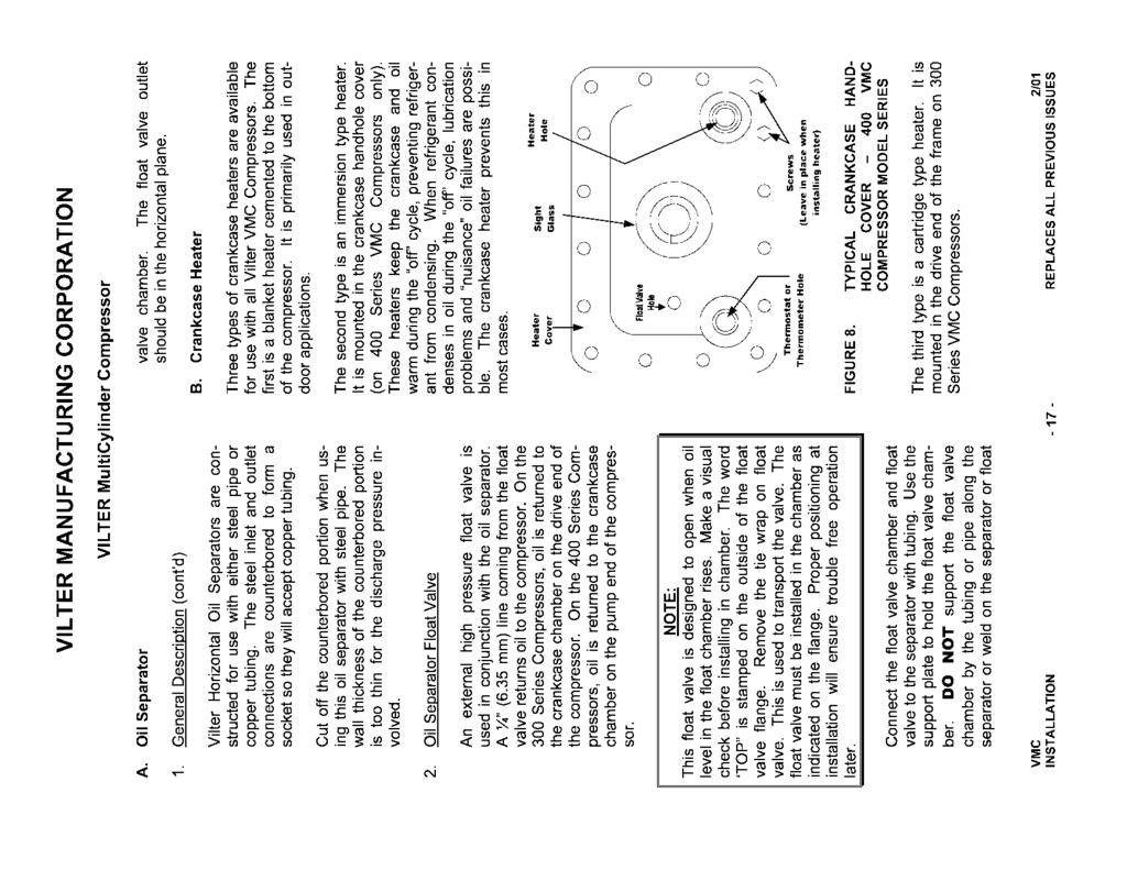
17
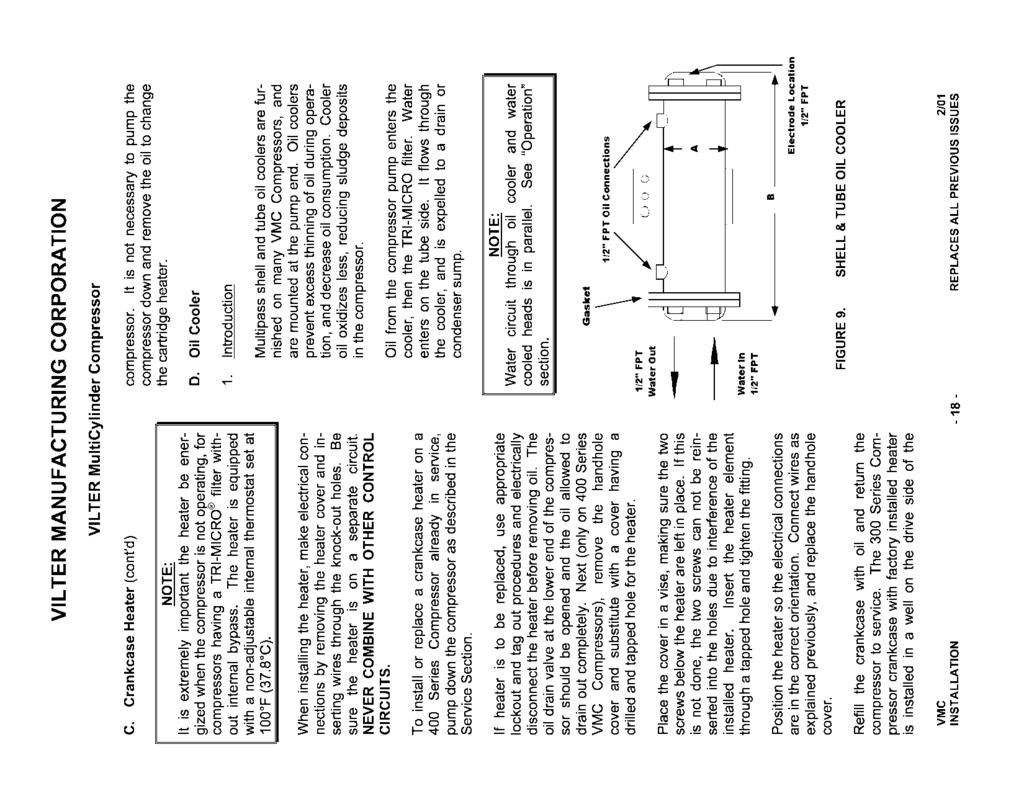
18
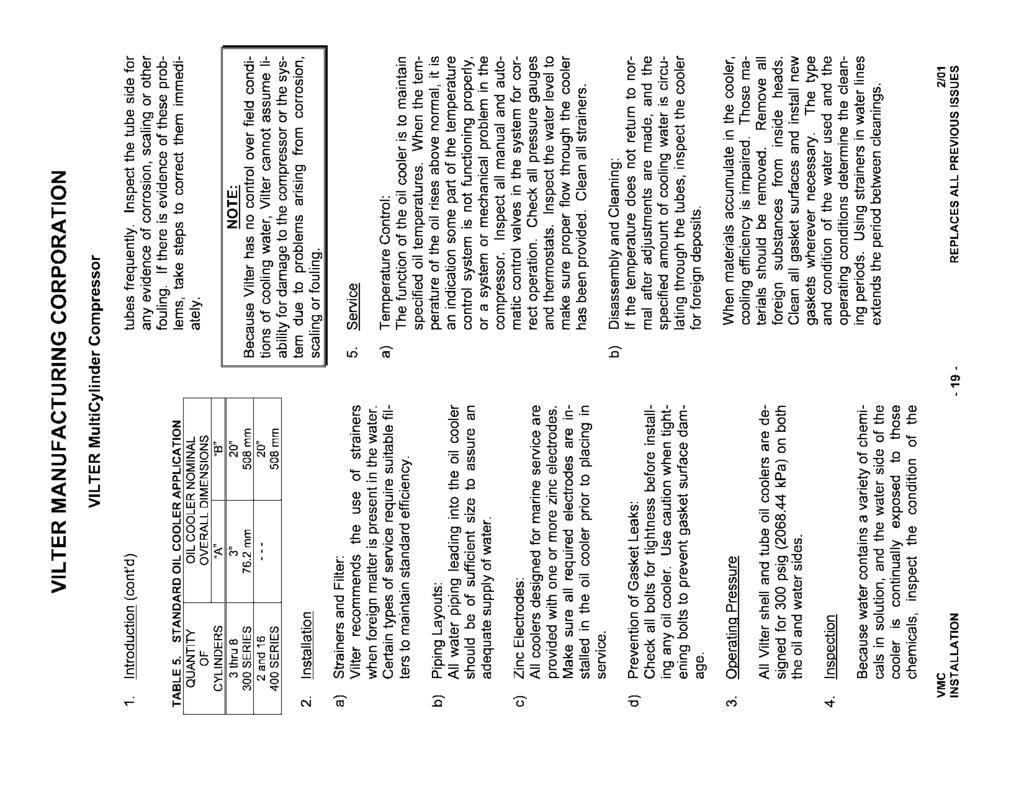
19
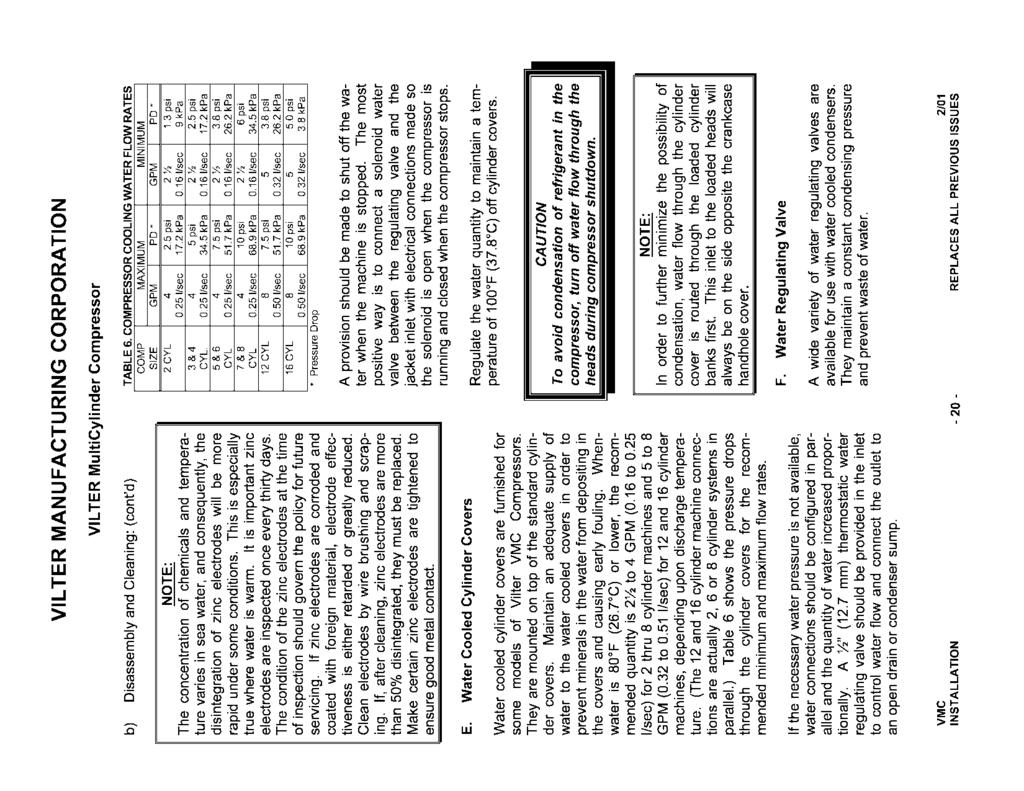
20
21
22
23
24
25
26

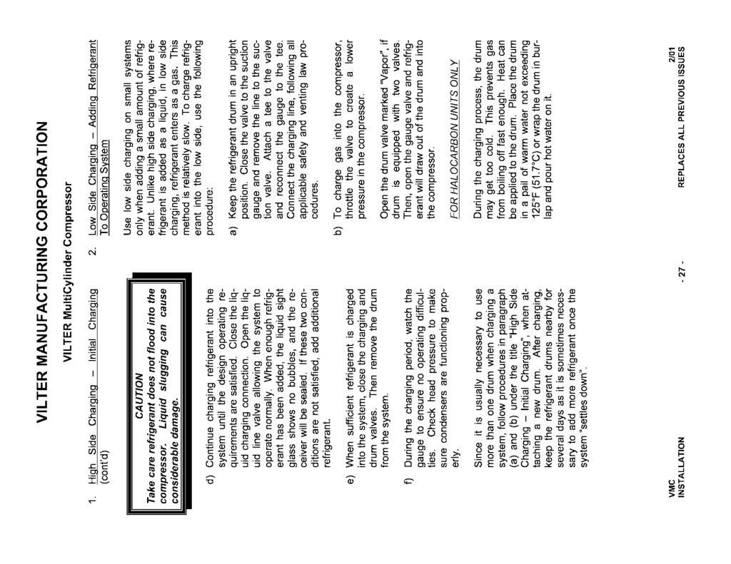
27
28

29
30
31
32
33
34
35
36
37
38
39

40

41

42
43
44
45
46
47
48
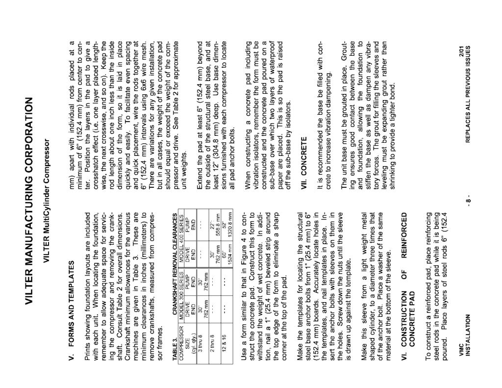
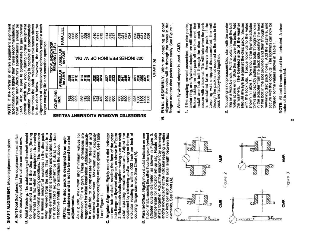
49 Vilter Stop/Check-Valve General Information AUTO In the Auto Position, the stop valve is operating as a check valve, allowing flow in the directions of the arrows. To set the valve to the automatic position, fully close the valve, and turn the stem out as indicated by the chart below. CLOSED In the manually Closed Postion, the stop check is operating as a convientional stop valve, not allowing flow in either direction. OPEN In the manually Open Position, with the valve stem fully back seated, the valve disc is lifted slightly, allowing flow in either direction.
50 Verify the location of Spring and note the direction of the Vilter name Installation: The new design will apply only to the 2 thru 4 stop valves. Retrofitting a field installation will require replacing the bonnet assembly. The bonnet must be installed with the spring towards the bottom (see illustrations above). The drill fixture is designed so that the hole for the spring will always be drilled on the opposite side from the cast in Vilter name on the bonnet. From the outside of the valve, the casting numbers must always be towards the top of the valve.
51
52
53
54

55

56
57

58
59

60
61
62
63
64
65
66
67
68
69
70
71
72
73
74
75
76
77
78
79
80
81
82
83
84
85
86

87 Master Catalog 125 Pressure Controls Section P Product/Technical Bulletin P28 Issue Date 0498 P28 and P128 Series Lube Oil Controls with Built-in Time Delay Relay The P28 and P128 Series Lube Oil Controls provide dependable and economical oil pressure cut-out for pressure-lubricated refrigeration compressors. The field-adjustable pressure differential of these controls provides compressor operation according to the manufacturer s specifications. The P28 and P128 controls operate by measuring the net lube oil pressure and de-energizing the compressor if the pressure falls below the differential setpoint. Manual or automatic reset models are available with factory set and sealed time delays of 30, 45, 60, 90, or 120 seconds (all time delays may not be available on all models). The P128 is the same control as the P28 but with 1/4 inch male flare pressure connections. Figure 1: P128AA Features and Benefits Built-in Time Delay Relay with Ambient Compensation Trip-free Manual Reset Replaceable Time Delay Relay Assembly Available with Runlight and Alarm Terminals Minimizes timing fluctuations due to temperature variations Provides manual reset that cannot be overridden by pressing and holding the reset button Allows easy field replacement of the time delay relay and terminal board Allows the control to be wired for normal oil pressure runlight signals and shutdown alarm circuits for remote monitoring of oil pressure status 1998 Johnson Controls, Inc. 1 Part No , Rev. A Code No. LIT
88 I ntroduction! WARNING: Personal injury hazard. All P28 and P128 controls are designed as lubrication protection controls. Failure of the P28 or P128 could allow the refrigeration compressor to be damaged in a way that may not be apparent upon visual inspection. Follow proper procedures and the compressor manufacturer s instructions, as well as any warning signs on or around the equipment, when discharging and disassembling the compressor. Environmental damage hazard. If leakage of sensed media (such as refrigerant or oil) can be harmful to the environment, or hazardous in any way, user must provide for proper containment. The P28 and P128 controls measure the net oil pressure available to circulate oil throughout a pressure-lubricated refrigeration system. The net oil pressure is the difference between the oil pressure at the pump discharge and the refrigerant pressure in the compressor crankcase. Example: If the oil pressure pump discharge reading is 90 psi (621 kpa) and the crankcase pressure is 70 psi (483 kpa), the net oil pressure is 20 psi (138 kpa). The P28 and P128 have a built-in time delay relay. This relay allows the oil pressure to build up for the time delay period before the compressor trips. This also prevents nuisance lockouts due to intermittent loss of oil pressure. The time delay relay is a trip free device. The manual reset cannot be overridden by pressing and holding the reset button. Manual reset models are available with time delays of 30, 45, 60, 90, or 120 seconds. Automatic reset models are available with a 90-second time delay. The time delay relay is compensated to minimize the effect of ambient temperature variations. However, the time delay relay will be affected by voltage variations. Dimensions Figure 2: P28 or P128 Dimensions (in./mm) O peration When the compressor starts, the timer is energized because the net oil pressure of the system is zero. During normal operation, the net oil pressure should build up to the pressure switch s cut-out setting (scale setting) plus the switch differential (3 to 5 psi [21 to 34 kpa]) within the required time delay, causing the time delay relay to de-energize. If the net oil pressure does not rise to the cut-out pressure setting plus the switch differential within the required time delay, the time delay relay trips and stops the compressor. If the net oil pressure drops below the cut-out pressure setting during the compressor s run cycle, the time delay relay energizes. If the net oil pressure returns within the time delay, the time delay relay deenergizes and the compressor continues to operate normally. If the net oil pressure does not return within the time delay, the control shuts down and locks out the compressor. 2 P P28 and P128 Series Lube Oil Controls with Built-in Time Delay Relay Product/Technical Bulletin
89 Example: Net oil pressure (oil pump pressure minus crankcase pressure) required to the bearings is 9 psi (62 kpa). The control scale setting should be 9 psi (62 kpa). The switch differential is 5 psi (34 kpa). Upon initial start of the compressor, the time delay relay energizes. If the net oil pressure does not build up to 14 psi (97 kpa), or the scale setting (9 psi) plus the switch differential (5 psi), during the time delay, the control breaks the circuit to the compressor. If the pressure of 14 psi (97 kpa) is reached during the time delay, the time delay relay de-energizes and the compressor continues to operate normally. Installation Mounting! CAUTION: Equipment damage hazard. A P28AN or P28DN control used for ammonia service must be mounted separately from the electrical cabinet. An ammonia leak could damage the electrical circuitry. Do not use Johnson Controls/Penn Ecosafe hose tubing in applications with ammonia or other corrosive refrigerants. Corrosion could cause tube breakage and refrigerant leakage. Use only the mounting screws supplied with the control. Damage to internal components may occur if other screws are used. The P28 and P128 controls are not position sensitive and can be mounted in any position. Use the two mounting screw holes located on the back of the control case to mount the control directly to a wall or panel board. Mount the control so that the pressure connections on the bellows are above the crankcase liquid level of the equipment being controlled. Note: When mounting the control to a compressor is required, a mounting bracket (Part No ) is available. Pressure Connections! CAUTION: Equipment damage hazard. Avoid sharp bends or kinks in the capillary or tubing to avoid damage to the capillary. Coil and secure excess capillary or tubing. Because harmonic vibration can break the capillary or tubing, some slack must be provided. Do not allow the capillary or tubing to rub against metal surfaces where friction can cause damage. When using a control with 1/4 in. / 6.4 mm tubing, a pulsation damper must be used. Pulsation can cause excessive wear and damage the control. 1. Purge all tubing and lines before connecting the pressure control. 2. Connect the oil pressure line pump discharge to the pressure connector labeled OIL. 3. Connect the crankcase pressure line to the pressure connector labeled LOW. 4. Coil and secure excess capillary or tubing to avoid vibration. Wiring! WARNING: Shock hazard. Disconnect all power supplies before making wiring connections to avoid electrical shock or damage to the equipment. Make all wiring connections using copper conductors only. Wire in accordance with National Electric Code and local regulations. For maximum electrical rating of the control, see the label inside the control cover. Use the terminal screws furnished (8-32 x 1/4 in. binder head). Substitution of other screws may cause faulty connections. P P28 and P128 Series Lube Oil Controls with Built-in Time Delay Relay Product/Technical Bulletin 3
90 See Figures 3 through 10 for typical wiring diagrams or refer to the compressor manufacturer s specifications. When the P28 or P128 control is supplied with a Terminal 3, it may be wired to operate a runlight for indicating when there is sufficient net oil pressure. When the control is supplied with a Terminal A, it can be wired to operate a shutdown alarm or signal for indicating when the compressor has tripped. For applications using a 208V control circuit, it is suggested that one leg of the 208V circuit and a neutral or ground wire be used as a 120V source to power the time delay relay. When a P28 or P128 is installed on a 440 or 550 VAC system, use an external step-down transformer to provide either 120 or 240V to the pilot and time delay relay circuits. The transformer must be of sufficient volt ampere capacity to operate the motor starter and the time delay relay. Table 1 presents the power requirements for the P28 or P128 time delay relay. Table 2 presents the electrical ratings. Table 1: Electrical Power Required for Time Delay Relay Voltage Timing in Seconds 12, 24, or 120V 240V 30, 45, 60, 90, or VA 30 VA Table 2: Electrical Ratings--Pilot Duty Time Delay Relay Circuit Pilot Circuit Alarm Circuit* Crankcase Heater** (Terminal 1) Runlight** (Terminal 3) 120/240 VAC 750 VA, 120/240 VAC 10W Tungsten, 120/240 VAC 10 Ampere, 120 VAC 5 Ampere, 240 VAC 24 VAC/VDC 12 VAC/VDC 125 VA, 24 VAC 57.5 VA, 24 VDC * Must be the same voltage as the pilot circuit. ** Must be the same voltage as the time delay relay circuit. 125 VA, 24 VAC 57.5 VA, 24 VDC 10W Tungsten -- 10W Tungsten Low 120/240 Models Low PC 2 1 PC 1 2 H TD 2 L TD 1 M A 120 DR Oil Oil Low Voltage Models 3 PC 2 1 PC 1 TD 2 L TD 1 2 H M A 24* *12 volt also available. PC 1 - Pressure actuated contacts. Open on increase in pressure difference between oil and low pressure conntectors. Makes and breaks time delay heater circuit. PC 2 - Contacts close simultaneously when PC 1 contacts open (runlight circuit). TD 1 - Time delay relay. Contacts open after time delay interval if pressure dfference between oil and low pressure connectors is not established or maintained. TD 2 - Contacts close simultaneously when TD 1 contacts open (alarm circuit). DR - Voltage dropping resistor used in dual voltage models. H - Heater for time delay relay. Connect Terminals L and M as a single pole switch. Connect Terminals 2 and 240 or 120 to energize circuit only when motor starter is closed. Figure 3: P28 or P128 Internal Wiring Circuit, Showing Alarm Circuit and Runlight Terminals 4 P P28 and P128 Series Lube Oil Controls with Built-in Time Delay Relay Product/Technical Bulletin
91 Additional controls in this line only. 240V 3-phase L 1 L 2 L 3 Ground 120 or 240V Supply Hot Any Voltage C 2 L1 L 2 L 3 Crankcase Heater When Used* 1 2 L M A P28 or P128 Operating Control T 1 T 2 T 3 Motor Crankcase Heater When Used* Alarm if Used * Runlight if Used 240 L M A 120 P28 or P or 120V Operating Control C 3 C 4 T 1 T 2 T 3 Motor Additional controls in this line only. *Crankcase heater cannot be cycled with this hookup. See Figure 5. Figure 4: P28 or P128 Used on a 240V System with 240V Magnetic Starter Coil *When crankcase heater is used, disconnect jumper from 2 to M and reconnect from 2 to L. Figure 6: P28 or P128 Where Separate Supply is Provided for Control Circuit (Jumper between 2 and M [or L] must be field installed.) Crankcase Heater When Used* Alarm if Used Additional controls in this line only. Runlight if Used 3 1 2* L M A P28 or P128 Operating Control 240V 3-phase L 1 L 2 L 3 T 1 T 2 T 3 Motor *When crankcase heater is used, disconnect jumper from 2 to M and reconnect from 2 to L. Figure 5: P28 or P128 Wired for 3-wire Control (Jumper between 2 and M [or L] must be field installed.) Crankcase Heater When Used* Alarm if Used * L A 240V Runlight if Used 240 M 120 P28 or P128 Operating Control 440V 440V 3-phase C 2 L 1 L 2 L 3 T 1 T 2 T 3 Motor Additional controls in this line only. *When crankcase heater is used, disconnect jumper 2 to M and reconnect 2 to L. Also, make sure that control circuit transformer has sufficient output for additional load. Figure 7: P28 or P128 Wired for 440V Supply and 240V Magnetic Start Coil (Also for 550V Using Proper Transformer) (Jumper between 2 and M [or L] must be field installed.) C 3 P P28 and P128 Series Lube Oil Controls with Built-in Time Delay Relay Product/Technical Bulletin 5
92 240V 3-phase Compressor Operating Control 240 V Start L 1 L 2 L 3 Motor L 1 L 2 L 3 C 2 Crankcase Heater When Used* Alarm if Used * Runlight if Used L M A P28 or P128 Stop Additional controls in this line only. Motor *When crankcase heater is used, disconnect jumper from 2 to M and reconnect 2 to L. C 3 T 1 T 2 T 3 Figure 8: P28 or P128 Where Manual Start-Stop Pushbutton Station is Used (Jumper between 2 and M [or L] must be field installed.) Alarm if Used L M A 24* P28 or P128 Transformer Starter Coil Operating Control *12 volt also available. 240V 3-phase L 1 L 2 L 3 T 1 T 2 T 3 Motor Additional controls in this line only. Figure 9: P28 or P128 Where 24V Control Circuit Power is from a Step-down Transformer (Jumper between 2 and M must be field installed.) Low Oil P74AA Low Oil P28/P L 2 M Junction Box T 1 T 2 T 3 Note:This system would provide shutdown on low lube oil pressure in either of two compressors operated by the common motor. Figure 10: P28 or P128 and P74AA Wired for an Oil Pressure Control System Where One Motor Operates Two Compressors Adjustments The P28 and P128 controls are shipped with a cut-out pressure differential of 9 psi (62 kpa). However, the controls can be adjusted according to the compressor manufacturer s specifications. Note: When the controls are shipped as an accessory to the compressor unit, time delay and cut-out pressure are set to manufacturer s specifications. Replacement controls should duplicate the manufacturer s specifications.! CAUTION: Equipment damage hazard. To avoid damage to the compressor, obtain the compressor manufacturer s net oil bearing pressure specifications as soon as possible. If necessary, reset the cut-out pressure difference to the manufacturer s specifications. When the manufacturer s specifications are not known, proceed as follows to set the cut-out pressure differential: 1. With the compressor running, read the oil pressure and the crankcase pressure. 2. Subtract the crankcase pressure reading from the oil pressure pump discharge reading. This is the net oil pressure to the bearings. 6 P P28 and P128 Series Lube Oil Controls with Built-in Time Delay Relay Product/Technical Bulletin
93 3. Set the cut-out pointer 6 to 8 psi (41 to 55 kpa) below the established running net oil pressure with the Adjusting Disk using a standard screwdriver. To increase the cut-out pressure, turn the Adjusting Disk counterclockwise. To decrease, turn clockwise. To raise the pressure differential, turn the Adjusting Disk (see Figure 2) to the left when viewing the front of the control. Turn the adjusting disk to the right to lower the pressure differential. Test for Shutdown Immediately after installing, and at regular intervals thereafter, the time delay relay should be tested to verify that all circuits are operating correctly.! WARNING: Shock hazard. Disconnect power from the control before testing for shutdown to avoid electrical shock or damage to the equipment. To test for shutdown: 1. Remove power from the control and remove the control cover. 2. Connect a jumper between Terminals 1 and 2. See Figure 3 for terminal locations. Note: If the control is mounted on a condensing unit where air from auxiliary equipment (blowers or fans) may strike the control, the control cover should be replaced before proceeding to Step Apply power to start the compressor. The time delay relay should trip after the time interval and stop the compressor. 4. Remove power from the control and remove the jumper between Terminals 1 and Replace the cover on the control and apply power. 6. Manually reset the time delay relay if required. Checkout Procedure Before leaving the installation, observe at least three complete operating cycles to be sure that all components are functioning correctly. Fungus Proofing Fungus proofing can be supplied at extra cost when specified. Conforms to government specifications MIL-V-173A. Repairs and Replacement Field repairs must not be made, except for replacement of the time delay relay assembly. For a replacement control or time delay relay assembly, contact the nearest Johnson Controls representative or Refrigeration Application Engineering at Table 3: Replacement Time Delay Relay Assemblies Part Number Voltage Reset Type Timing in Seconds Alarm Circuit RLY13A-600R 120/240 VAC Manual 60 No RLY13A-602R 120/240 VAC Manual 90 No RLY13A-603R 120/240 VAC Manual 90 Yes RLY13A-608R 120/240 VAC Automatic 90 No RLY13A-609R 24 VAC/VDC Manual 120 No RLY13A-610R 120/240 VAC Manual 30 No RLY13A-616R 120/240 VAC Manual 120 No RLY13A-617R 120/240 VAC Manual 45 No P P28 and P128 Series Lube Oil Controls with Built-in Time Delay Relay Product/Technical Bulletin 7
94 O rdering Information Table 4: Ordering Information Series Part Number Pressure Connections* P28AA Style 13, Style 5, or Style 15 Reset Type Refrigerant Time Delay Relay Voltage Manual Non-corrosive All-range P128AA Style 5 Manual Non-corrosive All-range Alarm Terminal Runlight Terminal 120/240 VAC No No 120/240 VAC No No P28AN Style 15 Manual Ammonia 120/240 VAC No No P28DA Style 13 Manual Non-corrosive All-range 120/240 VAC Yes Yes P28DN Style 15 Manual Ammonia 120/240 VAC Yes Yes P28GA Style 13 Automatic Non-corrosive All-range P28NA Style 13 or Style 5 Manual Non-corrosive All-range P28PA Style 5 Manual Non-corrosive All-range 120/240 VAC No No 24 VAC/VDC No No 24 VAC/VDC No No * Style 5 connections are 1/4 in. / 6.4 mm SAE male flare connectors (no capillary tubing). Style 13 connections are 36 in. / 914 mm capillary tubing and 1/4 in. / 6.4 mm flare nut. Style 15 connections are 1/4 in. / 6.4 mm female National Pipe Thread connectors. Specifications Product Power Requirements See Tables 1 and 2. P28 and P128 Series Lube Oil Controls with Built-in Time Delay Relay Pressure Specifications Adjustable Cut-out Pressure Difference: 8 to 70 psi (55 to 483 kpa)* Maximum Differential: 70 psi (483 kpa) Maximum Working Pressure: 250 psig (1724 kpa) on the high side Maximum Overpressure: 325 psi (2240 kpa) oil and low side pressure *The time delay relay is de-energized 3 to 5 psi (21 to 34 kpa) above the cut-out scale setting. Pressure Switch Units Enclosed Dust-protected Pennswitch Ambient Operating Conditions 32 to 104 F / 0 to 40 C Material Case: in. / 1.6 mm Galvanized Steel Cover: in. / 0.7 mm Cold Rolled Steel (plated and painted) Mounting Flat Surface or with a Universal Mounting Bracket (Part No ) Wiring Terminal Large 8-32 x 1/4 in. Binder Head Screws Agency Listings UL Guide No. SDFY; File SA516** CSA Class No ; File LR948** **Most models. Contact Johnson Controls for a complete listing. Dimensions (H x W x D) 5.66 x 5.32 x 2.09 in. / 144 x 135 x 53 mm Shipping Weight 3.0 lb / 1.36 kg The performance specifications are nominal and conform to acceptable industry standards. For application at conditions beyond these specifications, consult the local Johnson Controls Refrigeration Application Engineering at (414) Johnson Controls, Inc. shall not be liable for damages resulting from misapplication or misuse of its products. Controls Group FAN E. Michigan Street Master Catalog P.O. Box 423 Printed in U.S.A. Milwaukee, WI P P28 and P128 Series Lube Oil Controls with Built-in Time Delay Relay Product/Technical Bulletin


95 A70, A72 Series Temperature Controls for Refrigeration and Heating Master Catalog 125 Temperature Controls Section A Product Bulletin A70, A72 Issue Date 0996 Application The A70 single-pole and A72 two-pole controls are supplied in a wide selection of ranges to meet most application needs. See Temperature Ranges. Models may be supplied to open a circuit on temperature increase or close a circuit on temperature increase as required. An A70 single-pole control may optionally include a separate reverse-acting auxiliary contact. Models are available with a SPDT enclosed Pennswitch. All Series A70, A72 controls are designed for use only as operating controls. Where an operating control failure would result in personal injury and/or loss of property, it is the responsibility of the installer to add devices (safety, limit controls) or systems (alarm, supervisory systems) that protect against, or warn of, control failure. Specifications Features Long life contact structure with high contact force right up to break -- no bounce on make. Make reset models are trip-free. Ranges available to cover most applications. Auxiliary contact can be used to actuate an alarm circuit when the main contact opens. Two-pole construction provides a number of application advantages (see General Description ). Heavy gauge low profile stainless steel element cup to protect against mechanical damage. Fig Single function temperature control, Style 1. General Description The A70 controls provide dependability and quality at attractive prices. The A72 DPST controls provide a number of application advantages such as: Control of polyphase motors without use of magnetic starters where protection against overloading and single phasing is otherwise provided. Provides two separate control circuits necessary for the control of multiple systems. One set of contacts breaks the hot line when wired as a twopole switch in single-phase circuits. Permits control of two separate load circuits. Automatic control of heavy electrical loads. All A70, A72 controls have a single calibrated scale which shows directly both cut-in and cutout settings. Adjustments can be made readily without removing the cover Johnson Controls, Inc. 1 Code No. LIT
96 Optional Constructions Adjusting Knobs May be supplied on differential or range adjusting screw for limited adjustment within specified limits. Adjustment Cutout Stops Cutout stops, factory set as specified. Bulb and Capillary Standard bulb and capillary are copper. Stainless steel, monel and steel bulbs are available, if required. Bulb and capillary with neoprene coating to military specifications MIL-R-3065, Grade SB-515-ABFF may be supplied at additional cost. Capillary length 6 ft (1.8 m) only. Covers Standard finish is gray enamel. Stainless steel covers available at slight additional cost for exposed installations. Fungus Proofing Supplied at extra cost, when specified. Conforms to government specifications MIL-V-173A. Manual Reset Provides lockout which requires manual reset before a restart is possible. Manual reset is tripfree and cannot be blocked or tied down. Button must be pressed and released before operation will resume. Metric Scale Plates Temperature models are available with Celsius plates. Mounting Brackets Controls are supplied less bracket unless specified. Controls may be supplied with mounting brackets at additional cost. Part No is standard. Fig Standard mounting bracket Bulb Wells Supplied at extra cost, when specified. Capillary Tubing Standard temperature elements supplied with 6 ft (1.8 m) capillary. Extra length tube available at additional cost. Longer capillary tube supplied up to 10 feet (3 m) in 2 foot (0.6 m) increments; over 10 feet (3 m) in 5 foot (1.5 m) increments. Contact Action Open on rise or close on rise as specified. Type Number Main Contact Action No. of Poles Type Number Selection Lockout with Manual Reset Temperature Elements Standard temperature element styles are shown on Page 5. For styles other than shown, please check with the nearest Johnson Controls district office or Customer Service. Knob Conduit Opening Misc. Single-Pole A70AA Open Low 1 No No 1/2 in. A70AQ Open Low 1 No Yes 1/2 in. Manual Start A70BA Open Low 1 Yes No 1/2 in. A70DA Open High 1 Yes No 1/2 in. A70GA Open Low 1 No No 1/2 in. Reverse Acting Aux. Contact A70HA Open Low 1 Yes No 1/2 in. Reverse Acting Aux. Contact A70JA Open High 1 No No 1/2 in. Reverse Acting Aux. Contact A70KA Open High 1 Yes No 1/2 in. Reverse Acting Aux. Contact Two-Pole A72AA Open Low 2 No No 3/4 in. A72AC Open Low 2 No No 3/4 in. No Cover A72AE Open Low 2 No No 3/4 in. Outdoor Case A72AP Open Low 2 No No 3/4 in. Manual Start A72CA Open High 2 No No 3/4 in. A72CE Open High 2 No No 3/4 in. Outdoor Case 2 A70, A72 Product Bulletin


97 P74 Series Differential Pressure Controls Master Catalog 125 Pressure Controls Section P Product Bulletin P74 Issue Date 0204 Application These differential pressure controls are for use as operating controls and/or indicating system functions through display lights or panels. They measure the difference in pressure exerted upon its two sensing elements. The controls are available for applications sensing air, oil or liquid. Typical applications are proof of flow across a chiller or water cooled condenser, proof of flow in a heating or cooling coil and lube oil pressure sensing on refrigeration compressors. On a proof of flow application the control measures pressure drop across two different points in either a closed water circulating system or a city water to supply system. Specifications Fig. 1: P74 Differential Pressure Control with Style 13 elements. On a proof of flow application in a water chiller system the control activates a light or signal to indicate a loss of water. The control may also be applied as a lube oil pressure sensing control on refrigeration compressors. They may be used in combination with P28 and/or P45 oil pressure cutout controls on two compressor, single motor units to reduce the oil system cost. (See Fig. 4.) Special low pressure models are available for variable speed and screw compressor oil pressure applications. All Series P74 differential pressure controls are designed for use only as operating controls. Where an operating control failure would result in personal injury and/or loss of property, it is the responsibility of the installer to add devices (safety, limit controls) or systems (alarm, supervisory systems) that protect against, or warn of, control failure Johnson Controls, Inc. 1 Part No , Rev. C Code No. LIT
98 Range and Differential Specifications Features Electrical Ratings Heavy duty, low profile elements withstand unduly high overrun pressures that may be encountered in shipment or in some machine rooms. Lockout models have a trip-free manual reset. Long life contact structure with high contact force -- no contact bounce. Single unit mounting and wiring -- saves installation time and material. General Description Single and double pole models are available with contacts that open on a pressure differential increase or close on a pressure differential increase. Also available are models with singlepole, double-throw enclosed contacts or with main and separate reverse-acting auxiliary contacts. Controls with lockout feature require manual reset to reclose circuit after lockout. The trip-free reset will not permit restart until reset button is pushed and released. The operation point of the control is readily adjusted by rotating the adjusting disk. The control set points are easily read on a calibrated scale. 2 P74 Product Bulletin
99 Optional Constructions Pressure Elements Regularly supplied for noncorrosive refrigerants (fluorinated hydrocarbons). Available for ammonia service with 1/4 in FNPT connector (See Style Chart, Fig. 2.) Pressure Connectors Standard controls supplied with 36 in. capillary tubing with 1/4 in. flare nut (Style 13). Controls with 1/4 in. SAE male flare connector (no capillary tubing, Style 5), 36 in. capillary tubing with 1/4 in. sweat section (Style 34), or 1/4 in. FNPT connector (Style 15) may be supplied on quantity orders (see Pressure Element Styles). Repairs and Replacement Field repairs must not be made. For a replacement control, contact the nearest Johnson Controls distributor. 2. Complete Product Number, if available. 3. If complete Product Number is not available, specify Type Number (see Specifications table) and the following. 4. Type of refrigerant or fluid. a. Non-corrosive. b. Ammonia. Ordering Information 5. Style of pressure connector. To order, specify: 1. Quantity required. Fig. 3: Typical proof of flow hookup. 6. Optional constructions. 7. Setting -- contacts close at and open at. Fig. 2: Pressure element styles available on the P74. Style 13 is standard. Other styles shown above can be supplied on quantity orders. Fig. 4: Typical wiring diagram showing the P74AA and a P28 on a motor operating two compressors. P74 Product Bulletin 3
100 Performance specifications appearing herein are nominal and are subject to accepted manufacturing tolerances and application variables. Controls Group 507 E. Michigan Street P.O. Box 423 Milwaukee, WI Printed in U.S.A. 4 P74 Product Bulletin
 is ideally suited for")
101 Bulletin C401d March, 2002 HANSEN TECHNOLOGIES CORPORATION Specifications, Applications, Service Instructions & Parts HCK4 IN-LINE CHECK VALVES 5 /8" thru 4" PORT (16 thru 100 mm) Flanged 3 /8" thru 4" FPT, SW, WN, ODS for refrigerants HCK4-4 Check Valve INTRODUCTION The HCK4 series of dependable, compact, rugged in-line check valves (disc type non-return valves) is ideally suited for refrigerant flow control applications. Valves open wide for flow in the arrow direction on the valve body. Valves close quickly and reliably when flow reversals occur. KEY FEATURES Plated bodies and stainless steel seat discs and springs enable them to withstand expected industrial refrigeration conditions. Furthermore, these check valves can be mounted in any position, closecoupled to other valves, and use same flanges as Parker R/S, Frick, and Henry. ADVANTAGES These compact check valves offer reliable operation regardless of position. Corrosion resistant stainless steel seat disc. Metal-to-metal seats facilitate durable, tight closing of valves. APPLICATIONS These in-line check valves are designed to provide refrigerant flow control to hot gas lines, liquid lines, compressor discharge lines, suction lines, and hot gas heated drain pans. These valves are not recommended for use with pulsating loads such as low speed compressor discharge and screw compressor side port applications. For applications such as these, use Hansen HCK1 piston type check valves. ADDITIONAL FEATURES Mounts in any position Less than 1 PSID wide opening pressure Can be close-coupled Low bubble leakage tolerance For Ammonia, R22, R134a, and other approved refrigerants Dimensionally replaces R/S CK4A-2, -3, -4, -8, & -1 U.L. Listed
102 MATERIAL SPECIFICATIONS Body: 5 /8" thru 1¼": Steel, ASTM A108, zinc chromate plated 1½" thru 4": Ductile iron, ASTM A536, zinc chromate plated Seat Disc: Stainless steel Seat Cartridge: 5 /8" thru 1¼": Stainless steel, ASTM A582 1½" thru 4": Steel, ASTM A108, zinc chromate plated Spring: Stainless steel Safe Working Pressure: 400 PSIG (27 bar) Operating Temperature: -60F to 240F (-50 to 115 C) INSTALLATION Valve may be located in any position. Arrow on valve body should match direction of flow. Secure valve with gaskets between flanges and tighten bolts evenly. Do not use this valve or any component to align pipes or tighten gap between flanges. Do not install on inlet side of solenoid valves or control valves with electric shut-off or shut-off valves unless a relief valve is used from therein between piping. Do not install on inlet side of outlet pressure regulators where liquid may become trapped. Instead, check valves should be located on outlet side of these valves. Check valves can be closecoupled to other matching solenoid valves, pressure regulators, or strainers by using a Male Adapter Ring and longer bolts supplied when so specified on order. INSTALLATION DIMENSIONS D = Socket Weld Depth J = Weld Neck K = ODS Solder %*.&/4*0/ )$, )$, )$, )$, )$, )$, )$, )$, )$, -&55& /8" Ñ ž A 2.50" 3.25" 3.25" 3.25" 5.06" 5.06" 6.06" 6.06" 6.39" (64 mm) (83 mm) (83 mm) (83 mm) (129 mm) (129 mm) (154 mm) (154 mm) (162 mm) B 3.19" 4.50" 4.50" 4.50" 4.56" 4.56" 6.00" 6.00" 7.13" (81 mm) (114 mm) (114 mm) (114 mm) (116 mm) (116 mm) (152 mm) (152 mm) (181 mm) C 3.50" 4.50" 4.50" 4.50" 6.38" 6.38" 7.50" 7.50" 8.00" (89 mm) (114 mm) (114 mm) (114 mm) (162 mm) (162 mm) (191 mm) (191 mm) (203 mm) D 0.38" 0.50" 0.50" 0.50" 0.75" 0.75" 1.00" 1.00" 1.00" (10 mm) (13 mm) (13 mm) (13 mm) (19 mm) (19 mm) (25 mm) (25 mm) (25 mm) E = 1.03" 1.22" 1.22" 1.22" 2.56" 2.56" 2.92" 2.92" 3.50" (26 mm) (31 mm) (31 mm) (31 mm) (65 mm) (65 mm) (74 mm) (74 mm) (89 mm) F 1.50" 2.37" 2.37" 2.37" 3.62" 3.62" 4.84" 4.84" 6.06" (38 mm) (60 mm) (60 mm) (60 mm) (92 mm) (92 mm) (123 mm) (123 mm) (154 mm) G 1.56" 2.50" 2.50" 2.50" 4.56" 4.56" 6.00" 6.00" 7.13" (40 mm) (64 mm) (64 mm) (64 mm) (116 mm) (116 mm) (152 mm) (152 mm) (181 mm) H 2.19" 3.12" 3.12" 3.12" 3.06" 3.06" 4.00" 4.12" 5.00" (56 mm) (79 mm) (79 mm) (79 mm) (78 mm) (78 mm) (102 mm) (105 mm) (127 mm) J 3.26" 4" 4" 4" 6.06" 6.06" 7.06" 7.06" 9.89" (83 mm) (102 mm) (102 mm) (102 mm) (154 mm) (154 mm) (179 mm) (179 mm) (251 mm) K 0.33" 0.49" 0.59" 0.62" 0.71" 0.87" 0.96" 1.08" 1.40" (8 mm) (12 mm) (15 mm) (16 mm) (18 mm) (22 mm) (24 mm) (27 mm) (36 mm) Valve Cv (Kv) 5.8 (5) 8.2 (7) 11.7 (10) 14.0 (12) 39 (33) 50 (43) 74 (63) 93 (80) 210 (180) Pipe Size ½", ¾" ¾" 1" 1¼" 1½" 2" 2½" 3" 4" * Dimensionally replaces R/S check valve models CK4A-2, -3, -4, -8, and -1. = "E" dimension is check valve body outside edge to outside edge. Flange groove depth: nominal 0.12" each of two; gasket thickness: nominal 0.06" each of two. 2
103 *5&. %&4$3*15*0/ 25: 1"35/0 7BMWF"TTFNCMZ,JU Above Kit Consists of: 1 Seat Disc Closing Spring Seat Cartridge Seat Cartridge O-ring Flange Gasket Body, HCK Bolt ( 7 /16" - 14 x 3.25") Nut ( 7 /16" - 14) Flange (FPT, SW, WN, ODS) 2 FACTORY PARTS LIST HCK4-2 (2-BOLT) HCK4-2 (2-BOLT) HCK4-3, -4, -5 *5&. %&4$3*15*0/ 25: 1"35/0 7BMWF"TTFNCMZ,JU Above Kit Consists of: (2-BOLT) 1 Seat Disc Closing Spring Seat Cartridge Seat Cartridge O-ring Flange Gasket a Body, HCK b Body, HCK c Body, HCK Socket weld shown. FPT, weld neck, ODS: available. HCK4-3, -4, -5 (2-BOLT) 7 Bolt ( 5 /8" -11 x 4") Nut ( 5 /8" -11) Flange (FPT, SW, WN, ODS) 2 FACTORY HCK4-7, -8, -9, -0, -1 (4-BOLT) *5&. %&4$3*15*0/ 25: 1"35/0 1a Seat Disc 1½", 2" b Seat Disc 2½", 3" c Seat Disc 4" a Closing Spring 1½", 2" b Closing Spring 2½", 3" c Closing Spring 4" a Seat Cartridge 1½", 2" b Seat Cartridge 2½" c Seat Cartridge 3" d Seat Cartridge 4" a Seat Cartridge O-ring 1½", 2" b Seat Cartridge O-ring 2½", 3" c Seat Cartridge O-ring 4" a Flange Gasket 1½", 2" b Flange Gasket 2½" c Flange Gasket 3" d Flange Gasket 4" a Body, HCK b Body, HCK c Body, HCK d Body, HCK e Body, HCK a Bolt, HCK4-7, -8 ( 5 /8" - 11 x 6") b Bolt, HCK4-9, -0 (¾" - 10 x 7") c Bolt, HCK4-1 ( 7 /8" - 9 x 7.5") a Nut, HCK4-7, -8 ( 5 /8" - 11) b Nut, HCK4-9, -0 (¾" - 10) c Nut, HCK4-1 ( 7 /8" - 9) Flange (FPT, SW, WN, ODS) 2 FACTORY 3 Socket weld shown. FPT, weld neck, ODS: available. HCK4-7, -8, -9, -0, -1 (4-BOLT) Socket weld shown. Weld neck, ODS: available.
104 OPERATION HCK4 check valves are normally closed valves. As inlet pressure increases, it overcomes the closing spring force. As the seat disc is pushed back and away from the seat cartridge, flow through the valve occurs. The valve will remain open until the inlet pressure drops below the closing spring force or there is a flow reversal, at which time the seat disc will close against the seat cartridge, preventing reverse flow. SIZING Check valves are normally selected on the basis of line size. However, for gas flow applications at low load conditions, a minimum of 1 psid across the valve is essential. This will maintain valve at full open position. Valve Cv (Kv) is listed in the installation dimension table on page 2. Factory valve sizing assistance is available. SERVICE AND MAINTENANCE These valves are a reliable part of a refrigeration system. However, if valve does not appear to be operating satisfactorily, isolate it from the refrigeration system. Remove all refrigerant from associated piping and valves. Follow the guidelines in the caution section. Loosen each flange nut on the check valve. Break each flange gasket seal. Carefully loosen flange bolts one at a time, being cautious to avoid any refrigerant which still may be present. Remove check valve from flanges and inspect. Lapped seating surfaces should be smooth and free of pits or scratches. To confirm valve operation, move seat disc with eraser end of pencil. Movement should be free from friction. If not, disassemble and visually inspect for dirt in valve or burrs on seat disc. Clean or replace parts as necessary. Valve discs and seats can be restored by lapping on a flat plate. WARRANTY Hansen valves are guaranteed against defective materials or workmanship for one year F.O.B. our plant. No consequential damages or field labor is included. ORDERING INFORMATION, HCK4 CHECK VALVES 5:1& *;& NN '-"/(&$0//&$5*0/ 45:-&4*;&4 '15488/ 0%4 45% "-40 45% HCK4-2* 5 /8" (16) ½" 3 /8", ¾" 5 /8" HCK4-3* ¾" (20) ¾" 1", 1¼" 7 /8" HCK4-4* 1" (25) 1" ¾", 1¼" 1 1 /8" HCK4-5 1¼" (32) 1¼" ¾", 1" 1 3 /8" HCK4-7 1½" (40) 1½" 2" 1 5 /8" HCK4-8* 2" (50) 2" 1½" 2 1 /8" HCK4-9 2½" (65) 2½" 3" 2 5 /8" HCK4-0 3" (80) 3" /8" HCK4-1* 4" (100) 4" /8" * Replaces R/S CK4A-2, CK4A-3, CK4A-4, CK4A-8, & CK4A-1. HCK4-2 close-couples to HS6 & HS8 Solenoid Valves. HCK4-3, -4, & -5 close-couples to HS7 Solenoid Valve. FPT available only 3 /8" to 1¼". TO ORDER: Specify valve type, connection style and size, and close-coupling information if needed. TYPICAL SPECIFICATIONS "Refrigeration in-line check valves shall have steel or ductile iron bodies, stainless steel seat discs, stainless steel closing springs, and be suitable for a safe working pressure of 400 PSIG, as manufactured by Hansen Technologies Corporation type HCK4 or approved equal." Typical close-coupling to solenoid valve. Reassemble valve and insert between flanges. Replace and tighten bolts and nuts evenly. Carefully check for leaks before returning to service. CAUTION Hansen check valves are only for refrigeration systems. These instructions and related safety precautions must be completely read and understood before selecting, using, or servicing these valves. Only knowledgeable, trained refrigeration mechanics should install, operate, or service these valves. Stated temperature and pressure limits should not be exceeded. Valves should not be removed unless system has been evacuated to zero pressure. See also Safety Precautions in current List Price Bulletin and Safety Precautions Sheet supplied with product. Escaping refrigerant might cause personal injury, particularly to the eyes and lungs. ISO 9002 Hansen Technologies Corp. Burr Ridge, IL Cert. # Orlando, FL Cert. # HANSEN TECHNOLOGIES CORPORATION 6827 High Grove Boulevard Burr Ridge, Illinois U.S.A. Telephone: (708) FAX: (708) Toll-free: Hansen Technologies Corporation Printed in U.S.A.

105 SECTION A1 WOOD S SURE-GRIPTM QD BUSHINGS Provide a True Clamp Fit Are Easy to Install and Remove Permit Four-Way Mounting A1 1

 provides proper wedging action. Saw cut through flange and taper (and sometimes cut down into keyway also) to provide a true clamp fit.")
 which is about half the inclined angle of many other bushings.")


106 SURE-GRIP BUSHING FEATURES Sure-Grip Quick Detachable bushings are easy to install and remove. They are split through flange and taper to provide a true clamp on the shaft that is the equivalent of a shrink fit. All sizes except JA and QT have a setscrew over the key to help 6-hole drilling (most sizes) makes installation and removal quick and easy. Keyseat 180 from split. Precise taper (3/4 in. per ft. on diameter) provides proper wedging action. Saw cut through flange and taper (and sometimes cut down into keyway also) to provide a true clamp fit. Cap screws used to secure bushings to sheave and to remove bushing from sheave. maintain the bushing s position on the shaft until the cap screws are securely tightened. Sure-Grip bushings have a very gradual taper (3/4-inch taper per ft. on the diameter) which is about half the inclined angle of many other bushings. The result is the Sure-Grip securely clamps the shaft, with twice the force of those competitive bushings, to provide extreme holding power. Versatile Sure-Grip bushings permit the mounting of the same mating part on shafts of different diameters, and the mounting of different sheaves on the same shaft using the same bushing. Their interchangeability extends through sheaves, pulleys, timing pulleys, sprockets, flexible and rigid couplings, made-toorder items by Wood s, and to product lines of several other mechanical power transmission manufacturers. Sure-Grip bushings are manufactured with the drilled and tapped holes located at a precise distance from the keyseat; thus, a wide mating part having a bushing in each end can be mounted on a common shaft with the two keyways in line. This feature not only facilitates installation but also permits both bushings to carry an equal share of the load. STANDARD MOUNTING REVERSE MOUNTING 1. Cap screws from outside through drilled holes in the mating part and into threaded holes in the bushing flange located on the inside of the assembly. Or the complete assembly reversed on the shaft and; 2. Cap screws from inside through drilled holes in the mating part and into threaded holes in the bushing flange located on the outside of the assembly. 3. Cap screws from inside through drilled holes in the bushing flange located on the inside of the assembly and into threaded holes in the mating part. 4. Cap screws from outside through drilled holes in the bushing flange located on the outside of the assembly and into threaded holes in the mating part. A1 2
107 SURE-GRIP BUSHING DIMENSIONS Sure-Grip bushings are designed to transmit the rated torque capacity listed in the table below when the cap screws are tightened as indicated. The bushings are stocked in all popular bore sizes, including metric bores, within the bore range for a particular bushing. Bushing Bushings Bushings QT JA to J inclusive M to S inclusive w/setscrew w/setscrew Except JA SURE-GRIP BUSHING TORQUE RATINGS AND DIMENSIONS Torque (Note 1) (Note 2) Cap DIMENSIONS IN INCHES Bush. Capacity Max. Max. Bolt Screws (In.-Lbs.) Bore Bore A B D E F* L Circle Required QT 1, / /2 1 7 /8 1 1 / /4 x 1 JA 1, / /16 9 / / #10 x 1 SH 3, / /16 7 /8 13 / /4 2 1 /4 3-1 /4 x 1 3 /8 SDS 5, / /16 7 /8 3 /4 1 5 / / /4 x 1 3 /8 SD 5, / / /8 1 1 / / / /4 x 1 7 /8 SK 7, / / /8 1 3 /8 1 1 /4 1 7 /8 3 5 / /16 x 2 SF 11, / / /8 1 1 /2 1 1 / /8 3-3 /8 x 2 E 20, / / /8 1 5 /8 2 5 / /2 x 2 3 /4 F 40, / / / / /2 3 5 /8 5 5 /8 3-9 /16 x 3 5 /8 J 55, / /4 3 1 /2 3 3 / /2 6 1 /4 3-5 /8 x 4 1 /2 M 125, / / /8 5 1 /2 5 3 / /4 7 7 /8 4-3 /4 x 6 3 /4 N 150, / /8 6 1 /4 8 1 /8 8 1 /2 4-7 /8 x 8 P 250, / /4 7 5 /8 7 1 /4 9 3 / x 9 1 /2 W 375, / / / / /8 x 11 1 /2 S 625, / / / / /4 x 15 1 /2 * Mating hub length. 1. MAX INCH BORE WITH KEYSEAT. 2. MAX MM BORE WITH STANDARD KEYSEAT. See pages A1 4 to A1 8 for Bore and Keyseat information and weights. A1 3
108 SURE-GRIP BUSHINGS BORE AND KEYSEAT DIMENSIONS (Inches) Sure-Grip Bushings are available from stock with all the bores and keyseats listed below. In some cases, as the bore increases in diameter, a shallow keyseat is provided due to insufficient metal thickness. When this happens, Wood s furnishes the correct rectangular key to suit at no charge. This does not affect the bushing s ability to transmit the load. The rectangular key, or flat key as some call it, fits into the standard keyway in the shaft. Product Wt. No. Bore Key Seat (*) QT BUSHINGS QTMPB 7/16 No KS.6 QT12 1/2 1/8 x 1/16.6 QT9/16 9/16 1/8 x 1/16.6 QT58 5/8 3/16 x 3/32.6 QT11/16 11/16 3/16 x 3/32.6 QT34 3/4 3/16 x 3/32.6 QT13/16 13/16 3/16 x 3/32.6 QT78 7/8 3/16 x 3/32.6 QT15/16 15/16 1/4 x 1/8.6 QT1 1 1/4 x 1/8.6 QT /16 1/4 x 1/8.6 QT /8 1/4 x 1/8.6 QT /16 1/4 x 1/8.6 QT /4 1/4 x 1/8.6 QT /16 5/16 x 1/16.6 QT /8 5/16 x 1/16.6 QT /16 3/8 x 1/16.6 QT /2 3/8 x 1/16.6 JA BUSHINGS JAMPB 1/2 No KS.8 JA12 1/2 1/8 x 1/16.8 JA9/16 9/16 1/8 x 1/16.8 JA58 5/8 3/16 x 3/32.8 JA11/16 11/16 3/16 x 3/32.8 JA34 3/4 3/16 x 3/32.8 JA13/16 13/16 3/16 x 3/32.8 JA78 7/8 3/16 x 3/32.8 JA15/16 15/16 1/4 x 1/8.8 JA1 1 1/4 x 1/8.8 JA /16 1/4 x 1/16.8 JA /8 1/4 x 1/16.8 JA /16 1/4 x 1/16.8 JA /4 1/4 x 1/32.8 SH BUSHINGS SHMPB 7/16 No KS 1.1 SH12 1/2 1/8 x 1/ SH9/16 9/16 1/8 x 1/ SH58 5/8 3/16 x 3/ SH11/16 11/16 3/16 x 3/ SH34 3/4 3/16 x 3/ SH13/16 13/16 3/16 x 3/ SH78 7/8 3/16 x 3/ SH15/16 15/16 1/4 x 1/8 1.0 SH1 1 1/4 x 1/8.9 * Approximate weight in lbs. Product Wt. No. Bore Key Seat (*) SH BUSHINGS (continued) SH /16 1/4 x 1/8.9 SH /8 1/4 x 1/8.9 SH /16 1/4 x 1/8.8 SH /4 1/4 x 1/8.8 SH /16 5/16 x 5/32.7 SH /8 5/16 x 5/32.7 SH /16 3/8 x 1/16.7 SH /2 3/8 x 1/16.6 SH /16 3/8 x 1/16.6 SH /8 3/8 x 1/16.5 SH /16 No KS.5 SDS BUSHINGS SDSMPB 7/16 No KS 1.7 SDS12 1/2 1/8 x 1/ SDS9/16 9/16 1/8 x 1/ SDS58 5/8 3/16 x 3/ SDS11/16 11/16 3/16 x 3/ SDS34 3/4 3/16 x 3/ SDS13/16 13/16 3/16 x 3/ SDS78 7/8 3/16 x 3/ SDS15/16 15/16 1/4 x 1/8 1.5 SDS1 1 1/4 x 1/8 1.5 SDS /16 1/4 x 1/8 1.4 SDS /8 1/4 x 1/8 1.4 SDS /16 1/4 x 1/8 1.4 SDS /4 1/4 x 1/8 1.3 SDS /16 5/16 x 5/ SDS /8 5/16 x 5/ SDS13838KS 1-3/8 3/8 x 3/ SDS /16 3/8 x 3/ SDS /2 3/8 x 3/ SDS /16 3/8 x 3/ SDS /8 3/8 x 3/ SDS /16 3/8 x 3/ SDS /4 3/8 x 1/8 1.0 SDS /16 1/2 x 1/8.9 SDS /8 1/2 x 1/16.9 SDS /16 1/2 x 1/16.8 SDS2 2 No KS.7 SD BUSHINGS SDMPB 7/16 No KS 2.1 SD12 1/2 1/8 x 1/ SD9/16 9/16 1/8 x 1/ SD58 5/8 3/16 x 3/ SD11/16 11/16 3/16 x 3/ MPB Bushings are unsplit. Product Wt. No. Bore Key Seat (*) SD BUSHINGS (continued) SD34 3/4 3/16 x 3/ SD13/16 13/16 3/16 x 3/ SD78 7/8 3/16 x 3/ SD15/16 15/16 1/4 x 1/8 1.9 SD1 1 1/4 x 1/8 1.8 SD /16 1/4 x 1/8 1.8 SD /8 1/4 x 1/8 1.7 SD /16 1/4 x 1/8 1.7 SD /4 1/4 x 1/8 1.6 SD /16 5/16 x 5/ SD /8 5/16 x 5/ SD13838KS 1-3/8 3/8 x 3/ SD /16 3/8 x 3/ SD /2 3/8 x 3/ SD /16 3/8 x 3/ SD /8 3/8 x 3/ SD /16 3/8 x 3/ SD /4 3/8 x 1/8 1.1 SD /16 1/2 x 1/8 1.1 SD /8 1/2 x 1/ SD /16 1/2 x 1/16.9 SD2 2 No KS.8 SK BUSHINGS SKMPB 7/16 No KS 3.6 SK12 1/2 1/8 x 1/ SK9/16 9/16 1/8 x 1/ SK58 5/8 3/16 x 3/ SK11/16 11/16 3/16 x 3/ SK34 3/4 3/16 x 3/ SK13/16 13/16 3/16 x 3/ SK78 7/8 3/16 x 3/ SK15/16 15/16 1/4 x 1/8 3.4 SK1 1 1/4 x 1/8 3.3 SK /16 1/4 x 1/8 3.3 SK /8 1/4 x 1/8 3.2 SK /16 1/4 x 1/8 3.2 SK /4 1/4 x 1/8 3.1 SK /16 5/16 x 5/ SK151638KS 1-5/16 3/8 x 3/ SK /8 5/16 x 5/ SK13838KS 1-3/8 3/8 x 3/ SK /16 3/8 x 3/ SK /2 3/8 x 3/ SK /16 3/8 x 3/ SK /8 3/8 x 3/ SK / x 3/ SK /4 3/8 x 3/ SK13412KS 1-3/4 1/2 x 1/4 2.5 (Continued next page) A1 4
109 SURE-GRIP BUSHINGS BORE AND KEYSEAT DIMENSIONS Product Wt. No. Bore Key Seat (*) SK BUSHINGS (continued) SK /16 1/2 x 1/4 2.4 SK /8 1/2 x 1/4 2.4 SK /16 1/2 x 1/4 2.3 SK2 2 1/2 x 1/4 2.2 SK /16 1/2 x 1/4 2.1 SK /8 1/2 x 1/4 2.0 SK /16 1/2 x 1/8 2.0 SK /4 1/2 x 1/8 1.9 SK21458KS 2-1/4 5/8 x 1/8 1.9 SK /16 5/8 x 1/ SK /8 5/8 x 1/ SK /16 5/8 x 1/ SK /2 5/8 x 1/ SK /16 No KS 1.3 SK /8 No KS 1.1 SF BUSHINGS SFMPB 1/2 No KS 5.1 SF12 1/2 1/8 x 1/ SF58 5/8 3/16 x 3/ SF34 3/4 3/16 x 3/ SF78 7/8 3/16 x 3/ SF15/16 15/16 1/4 x 1/8 4.8 SF1 1 1/4 x 1/8 4.8 SF /16 1/4 x 1/8 4.7 SF /8 1/4 x 1/8 4.7 SF /16 1/4 x 1/8 4.6 SF /4 1/4 x 1/8 4.5 SF /16 5/16 x 5/ SF /8 5/16 x 5/ SF13838KS 1-3/8 3/8 x 3/ SF /16 3/8 x 3/ SF /2 3/8 x 3/ SF /16 3/8 x 3/ SF /8 3/8 x 3/ SF /16 3/8 x 3/ SF /4 3/8 x 3/ SF /16 1/2 x 1/4 3.8 SF /8 1/2 x 1/4 3.7 SF /16 1/2 x 1/4 3.6 SF2 2 1/2 x 1/4 3.5 SF /16 1/2 x 1/4 3.4 SF /8 1/2 x 1/4 3.3 SF /16 1/2 x 1/4 3.2 SF /4 1/2 x 1/4 3.1 SF21458KS 2-1/4 5/8 x 5/ SF /16 5/8 x 3/ SF /8 5/8 x 3/ SF /16 5/8 x 3/ SF /2 5/8 x 3/ SF /16 5/8 x 1/ SF /8 5/8 x 1/ SF /16 5/8 x 1/ SF /4 5/8 x 1/ SF /8 3/4 x 1/ SF /16 3/4 x 1/ (Inches) Product Wt. No. Bore Key Seat (*) E BUSHINGS EMPB 7/8 No KS 10.8 E78 7/8 3/16 x 3/ E15/16 15/16 1/4 x 1/ E1 1 1/4 x 1/ E /8 1/4 x 1/ E /16 1/4 x 1/ E /4 1/4 x 1/ E /16 5/16 x 5/ E /8 5/16 x 5/ E13838KS 1-3/8 3/8 x 3/ E /16 3/8 x 3/ E /2 3/8 x 3/ E /16 3/8 x 3/ E /8 3/8 x 3/ E /16 3/8 x 3/ E /4 3/8 x 3/ E /16 1/2 x 1/4 9.4 E /8 1/2 x 1/4 9.3 E /16 1/2 x 1/4 9.2 E2 2 1/2 x 1/4 9.0 E /16 1/2 x 1/4 8.9 E /8 1/2 x 1/4 8.8 E /16 1/2 x 1/4 8.6 E /4 1/2 x 1/4 8.5 E21458KS 2-1/4 5/8 x 5/ E /16 5/8 x 5/ E /8 5/8 x 5/ E /16 5/8 x 5/ E /2 5/8 x 5/ E /16 5/8 x 5/ E /8 5/8 x 5/ E /16 5/8 x 5/ E /4 5/8 x 5/ E /16 3/4 x 3/8 7.2 E /8 3/4 x 3/8 7.1 E /16 3/4 x 1/8 6.9 E3 3 3/4 x 1/8 6.7 E /8 3/4 x 1/8 6.3 E /16 3/4 x 1/8 6.0 E /4 3/4 x 1/8 5.8 E /16 7/8 x 1/ E /8 7/8 x 1/ E /16 7/8 x 1/ E /2 7/8 x 1/ F BUSHINGS FMPB 1 No KS 17.9 F1 1 1/4 x 1/ F /8 1/4 x 1/ F /16 1/4 x 1/ F /4 1/4 x 1/ F /8 5/16 x 5/ F /16 3/8 x 3/ F /2 3/8 x 3/ F /16 3/8 x 3/ F /8 3/8 x 3/ Product Wt. No. Bore Key Seat (*) F BUSHINGS (continued) F /4 3/8 x 3/ F /8 1/2 x 1/ F /16 1/2 x 1/ F2 2 1/2 x 1/ F /16 1/2 x 1/ F /8 1/2 x 1/ F /16 1/2 x 1/ F /4 1/2 x 1/ F21458KS 2-1/4 5/8 x 5/ F /16 5/8 x 5/ F /8 5/8 x 5/ F /16 5/8 x 5/ F /2 5/8 x 5/ F /16 5/8 x 5/ F /8 5/8 x 5/ F /16 5/8 x 5/ F /4 5/8 x 5/ F /16 3/4 x 3/ F /8 3/4 x 3/ F /16 3/4 x 3/ F3 3 3/4 x 3/ F /8 3/4 x 3/ F /16 3/4 x 3/ F /4 3/4 x 3/ F /16 7/8 x 3/ F /8 7/8 x 3/ F /16 7/8 x 3/ F /2 7/8 x 3/ F /8 7/8 x 3/ F /16 7/8 x 3/ F /4 7/8 x 3/ F /8 1 x 1/8 8.1 F /16 1 x 1/8 7.7 F4 4 No KS 6.9 J BUSHINGS JMPB 1-7/16 No KS 28.1 J /16 3/8 x 3/ J /2 3/8 x 3/ J /16 3/8 x 3/ J /16 3/8 x 3/ J /4 3/8 x 3/ J /8 1/2 x 1/ J /16 1/2 x 1/ J2 2 1/2 x 1/ J /8 1/2 x 1/ J /16 1/2 x 1/ J /4 1/2 x 1/ J /16 5/8 x 5/ J /8 5/8 x 5/ J /16 5/8 x 5/ J /2 5/8 x 5/ J /8 5/8 x 5/ J /16 5/8 x 5/ J /4 5/8 x 5/ J /8 3/4 x 3/ * Approximate weight in lbs. MPB Bushings are unsplit. (Continued next page) A1 5
110 VILTER MANUFACTURING CORPORATION VILTER MultiCylinder Compressor SERVICE SECTION TABLE OF CONTENTS (cont d) PAGE 16 SAFETY VALVE (INTERNAL RELIEF) 16 Removal 16 Replacement 17 OIL PRESSURE ADJUSTMENT ASSEMBLY 17 Disassembly 17 Reassembly 17 Adjustment 17 TRI-MICRO OIL FILTER 17 Removal 17 Replacement 18 OIL PUMP ASSEMBLY 18 Removal 18 Replacement 18 PREPARATION FOR INTERNAL SERVICING 18 Handhole Cover Removal 18 Handhole Cover Replacement 19 CRANKSHAFT SEAL 19 Oil Seal Leakage 19 Removal 19 Installing A New Shaft Seal 20 CONNECTING RODS AND PISTONS 20 Disassembly & 450 VMC Compressors Only XL VMC Compressor Only 20 Reassembly 23 CONNECTING RODS AND PISTONS 23 Disassembly & 450 VMC Compressors Only XL VMC Compressor Only 23 Reassembly 23 CYLINDER LINERS 23 Removal 24 Lift Rings For Unloading Lift Ring Assembly /450XL Lift Ring Assembly 24 Installation Of Liners 25 CRANKSHAFT 25 General 25 Removal From Drive End 25 Removal From The Pump End 26 Servicing The Center Bearing (12 & 16 Cylinders) 26 Reinstallation 24 MODIFICATION TO FRONT BEARING RETAINER AND FRONT BEARING COVER (440 Compressor Only) 31 CONNECTING ROD NUTS TIGHTENING INSTRUCTIONS VMC COMRPESSORS VMC SERVICE - B - REPLACES 2-01
111 VILTER MANUFACTURING CORPORATION VILTER MultiCylinder Compressor SERVICE SECTION ILLUSTRATIONS AND TABLES PAGE FIGURE 3 1 Bearing And Cylinder Covers Assembly & Disassembly Stud 5 2 Upper Cylinder Cross Section 6 3 Discharge Diaphragm Valve Placement 8 4 Flywheel Removal Tool 9 5 Unit Belting Requirements Due To Horsepower 11 6 Belt Tension Spring Scale 13 7 Typical Capacity Control Mechanism Arrangement 440 Compressor (Old Style Mushroom Type) 15 8 Typical Capacity Control Mechanism Arrangement 450 & 450XL Compressor (New Style Bulletin Type) 16 9 Safety Valve Location Piston Ring Compressing Tool Front Cover Assembly And Disassembly Tool Crankshaft Seal Assembly Piston Ring Dimensions Cylinder Liner Assembly Tool Cylinder Liner Removal Tool Retainer Partial Vertical Cross Section Typical 400 Series Compressor Vertical Cross Section and Lubricating System PAGE TABLE 23 1 Piston Ring Dimensions And Tolerances 28 2 Torque Specifications VMC Model Torque Specifications VMC Model Torque Specifications VMC Model 450XL 32 5 Factory Running Dimensions Tolerances, Clearances & Allowable Wear Limits For 440, 450 & 450XL VMC Compressors VMC SERVICE - C - REPLACES 2-01
112 VILTER MANUFACTURING CORPORATION VILTER MultiCylinder Compressor I. GENERAL SERVICE INSTRUCTIONS A. General Comments When working on the compressor, care must be taken to ensure contaminants, such as water from melting ice or snow, dirt, and dust, DO NOT enter the compressor while it is being serviced. It is essential that all dust, oil or ice that has accumulated on the outside of the compressor be removed before servicing. All gaskets, o-rings, roll pins and lock washers must be replaced when servicing and reassembling the compressor. As an aid in servicing compressors, a tool kit is available and can be ordered as Vilter Part No. KT067. This kit includes necessary wrenches as well as all the servicing tools pictured in this section. B. Preparation Of Compressor For Servicing Remove all refrigerant from the compressor before servicing it. To properly evacuate the compressor, employ the following procedure: 1. Refrigerant 717 (Ammonia) Compressor Shut down the unit, open the electrical disconnect switch and pull the fuses for the compressor motor to prevent the unit from starting. Put a lock on the disconnect switch and tag the switch to indicate maintenance is being performed. Isolate the unit by manually closing the discharge stop/check valve. Close the liquid supply valves and open all solenoid valves to prevent liquid refrigerant from being trapped between the stop valves and solenoid valves. Allow the unit to equalize to suction pressure before closing the suction stop/check valve. After the unit has equalized to suction pressure, depressurize the unit by using a pump down compressor or other acceptable means. Remove drain plugs from the bearing housings, compressor housing and discharge manifold. Drain the oil into appropriate containers. To blow off the gas caught between the discharge valves and discharge stop valve, close the gauge valve, remove gauge, connect one end of a hose to gauge valve, and put the other end in a bucket of water. Open the valve slowly and the water will absorb any discharged ammonia. Connect hose to the suction gauge connection in the same manner, and the water will absorb the rest of the ammonia. Do not leave hoses in the water if work has to stop and the frame is still warm. Cooling of the frame could siphon water back into the frame through the hose. 2. Halocarbon Refrigerant Compressor The procedure for removing halocarbon refrigerant from a compressor is NOT the same as described for an ammonia compressor. To evacuate a compressor using halocarbon refrigerant, employ certified technicians to pump down the unit according to applicable laws and ordinances. When the unit is pumped down, the temperature of the machine drops. Before opening the machine, allow it to warm up to room temperature. Opening the machine before it is warmed up produces condensation on the metal surfaces. Moisture is detrimental to compressor operation. It leads to system operating difficulties and rusting of parts. 400 Series VMC 2/01 SERVICE Replaces all Previous Issues
113 VILTER MANUFACTURING CORPORATION VILTER MultiCylinder Compressor 3. Compressor Oil Removal If service will be performed on unloader solenoids, oil filter change, suction or discharge valves, or crankshaft seal, the oil will not require removal. If it becomes necessary to open the crankcase, disconnect power to the heater and remove oil through the drain valve. If a slight positive pressure is allowed to remain in the crankcase before compressor is opened, it will force the oil from the drain valve into a container of sufficient capacity. It is best to have reduced the pressure to 2 psig (13.79 kpa) to minimize the amount of foaming. After the compressor has been serviced, do not reuse this oil. Even reconditioned oil contains contaminates that could cause compressor damage. C. Preparation Of Compressor For Initial Start After Servicing Vilter recommends charging 1 to 2 gallons of fresh oil into the compressor via the oil pressure gauge port in the front housing. This eliminates dry start-up by forcing oil into the passageways in the crankshaft, to the connecting rods, and having a good supply of oil for the shaft seal. Add oil to crankcase, via drain valve, to within 1/2 of the sight glass in the handhole cover. Connect power to the crankcase heater, close all open valves, and check for leaks. When oil has reached approximately 100 F (37.8 C), start the compressor and allow it to pull the load down gradually. Run the compressor for a few minutes, then stop for a cooling off period. Restart and run for a longer time. Stop and allow for a cooling off period again. Lengthen each running period until it is determined no moving parts are heating up excessively. When the compressor operates with normal running temperatures, allow it to run for whatever length of time the load requires. With new or replacement compressors, the suction bag should be removed after running for 24 hours. II. CYLINDER COVERS NOTE: Before proceeding, refer to Paragraph I, General Service Instructions. A. Disassembly To remove the compressor cylinder covers, remove the capacity control lines and water lines (or liquid cooling lines, if any) from the covers that will be removed. Next, remove two screws that are opposite each other diagonally across the cover (i.e. two screws by water connections). Install two assembly studs into these holes and tighten them to thread bottom. Screw on nuts to within one thread of touching the cover. Remove the other screws. Slowly back the two nuts off and make sure the cover follows. If the cover doesn t follow, STOP. DO NOT back off nuts more than one turn. Break the gasket seal and then continue cover removal. The studs are long enough to relieve all the spring tension before the nuts are removed. Remember, the studs must not be turned out with the nuts. After all of the spring tension is removed, the nuts can be removed, covers lifted off and head springs removed. It is best to keep all parts in the correct cylinder assignment. Invert the cover and place on work surface, placing each spring in its corresponding location in the cover. 400 Series VMC 2/01 SERVICE Replaces all Previous Issues
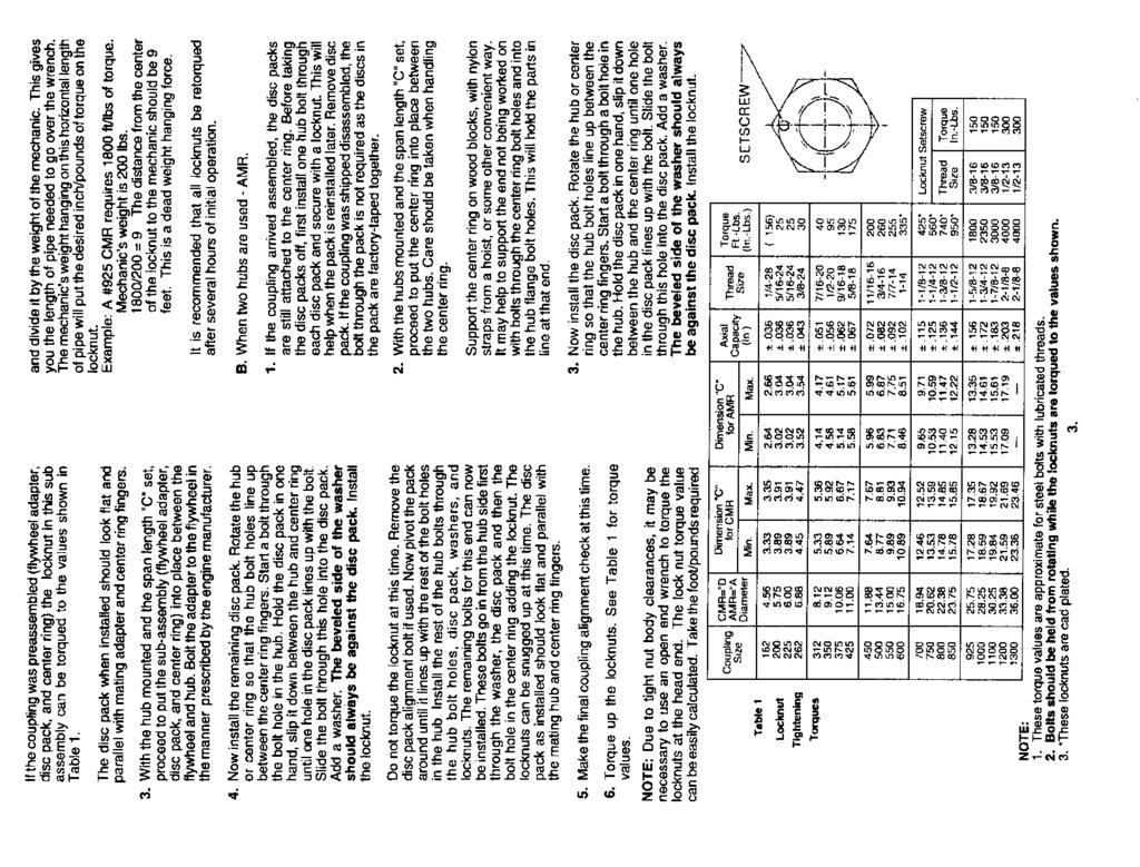
114 VILTER MANUFACTURING CORPORATION VILTER MultiCylinder Compressor A. Disassembly (cont d) III. SUCTION AND DISCHARGE VALVE PLATES NOTE: Before proceeding, refer to Paragraph I, General Service Instructions. A. Disassembly FIGURE 1. BEARING AND CYLINDER COVERS ASSEMBLY & DISASSEMBLY STUD B. Assembly Before replacing the cover on the compressor, inspect the gasket surfaces of the cover and compressor frame. Remove any debris adhering to either of these surfaces. Remove any burrs or rough edges from the mating surfaces to ensure a tight seal. Replace studs, if removed. Lightly lubricate both sides of the head gasket. Position the gasket over the studs and against the compressor frame in the correct orientation. Place the springs on top of the safety head yokes (rotating the spring until it stays on the yoke). Place the cover down over the studs and slowly lower on top of springs. When all pieces are in alignment, place the nuts on the studs and start to tighten. When the cover is secure within 1¼ (31.75 mm) of the gasket, install the rest of the screws so they come in contact with the cover. This will ensure they will not cross thread in the holes. Do not tighten each screw separately, however. Alternate on opposing screws, until the cover is seated on the gasket. Remove the studs and replace with screws. Finish tightening the screws in an opposing pattern to the recommended torque values shown in Table 2, 3 or 4 (depending upon your compressor model). Reinstall the capacity control and head cooling lines, and check for leaks. To service valve plates in the compressor, remove the cylinder covers (refer to paragraph II.A). In cylinders without unloaders, the valve assemblies may be removed as soon as the covers are removed. On compressor cylinders equipped with unloaders, the unloader needs to be forced down before the valves are serviced. If the unloader remains up, the suction valve is forced off its seat, and will not seat and locate properly during reassembly. To hold the unloader mechanism down, remove the plug from the hole B in the frame. Force the unloader piston down and insert a short 5 / 16 (7.93 mm) diameter metal rod through the hole to restrain the piston. Use a wooden block to force the piston down to avoid scratching or damaging the top of the unloader piston. Once the piston is held down, the valve assemblies can be serviced Compressor (Mushroom Style) (See Figure 7) Lift out the safety head yoke, which holds the safety head assembly in place. When the yoke is out, lift out the safety head assembly and suction valve plate. To disassemble the safety head assembly, remove the locknut on the valve retaining screw Compressor (Mushroom Style) (cont d) 400 Series VMC 2/01 SERVICE Replaces all Previous Issues
115 VILTER MANUFACTURING CORPORATION VILTER MultiCylinder Compressor Lift off the washer, two diaphragm valves, spacer and last diaphragm valve. Turn the safety head assembly over and remove the valve retaining screw. Remove the helical suction valve springs from their sockets with a twisting, pulling motion , 450XL Compressor (Bullet Style) (See Figure 8) Lift out the safety head yoke, which holds the safety head assembly in place. Invert the yoke to make sure all eight coil springs are intact within it. If any springs are broken, locate and remove pieces. Springs can be removed and replaced without tools. Since they are only finger tight in the bottom of the hole, they can be removed with a twisting, pulling motion. After the safety yoke has been removed, lift out the ring plate discharge valve (refer to note below). Slip the safety head up and off the roll pin that guides it. NOTE: Before removing valve plates, look for the word TOP etched on each plate and ring plate discharge valve. This denotes the unlapped upper face. If the etching is not clearly visible, dot the upper face of the valve plate with dye or tape. Do this sparingly. Any marking applied must be removed prior to reassembly. The safety head contains four helical suction valve springs, which are identical to the eight discharge valve springs. These need to be kept separated. The suction valve can be lifted out. Before reassembling the safety head assembly, the top of the discharge diaphragm valve must be determined. Place a straight edge on the diaphragms to reveal the dome. Diaphragms are installed with the dome on top. All pieces of the safety head assembly should be clean and lightly lubricated with compressor oil before reassembly. To reassemble the safety head assembly, insert the valve retaining screw in the safety head. Place one of the domed discharge diaphragm valves on the screw, making sure the dome is up. Next, place the thin spacer on the screw. Follow it with the two remaining diaphragms, both having the dome on top. Place the thicker washer and nut on the valve retaining screw. Tighten the nut to the torque value listed in Table 2, 3 or 4 (depending upon compressor model). Place the suction valve springs into the holes with the end that has two coils wound towards the bottom of the hole, and twist. The springs lock in place. When the springs are properly installed, the safety head can be inverted without the springs falling out. Place the suction valve plate in the cavity of the cylinder liner with the side marked TOP facing up. Ensure the valve plate rotates freely, without binding. Replace the safety head assembly in the frame. Be sure no debris or foreign material is on any parts. Replace safety yoke on top of the safety head assembly. B. Reassembly Compressor (Mushroom Style) 400 Series VMC 2/01 SERVICE Replaces all Previous Issues
 8 * Valve Washer 4 Safety Head Yoke 9 * Valve Spacer 5 Safety Head Spring")
116 VILTER MANUFACTURING CORPORATION VILTER MultiCylinder Compressor 5A 5A Compressor Frame KEY ITEM NO. ITEM NAME ITEM NO. ITEM NAME 1 Cylinder Liner 6 * Valve Retaining Screw 2 Suction Valve Plate 7 * Hexagon Lock Nut 3 Suction Valve Spring (4) 8 * Valve Washer 4 Safety Head Yoke 9 * Valve Spacer 5 Safety Head Spring (4) 10 * Diaphragm Discharge Valves (3) 5A Roll Pin (4) 11 * Safety Head FIGURE 2. UPPER CYLINDER CROSS SECTION 400 Series VMC 2/01 SERVICE Replaces all Previous Issues
117 VILTER MANUFACTURING CORPORATION VILTER MultiCylinder Compressor FIGURE 3. DISCHARGE DIAPHRAGM VALVE PLACEMENT 400 Series VMC 2/01 SERVICE Replaces all Previous Issues
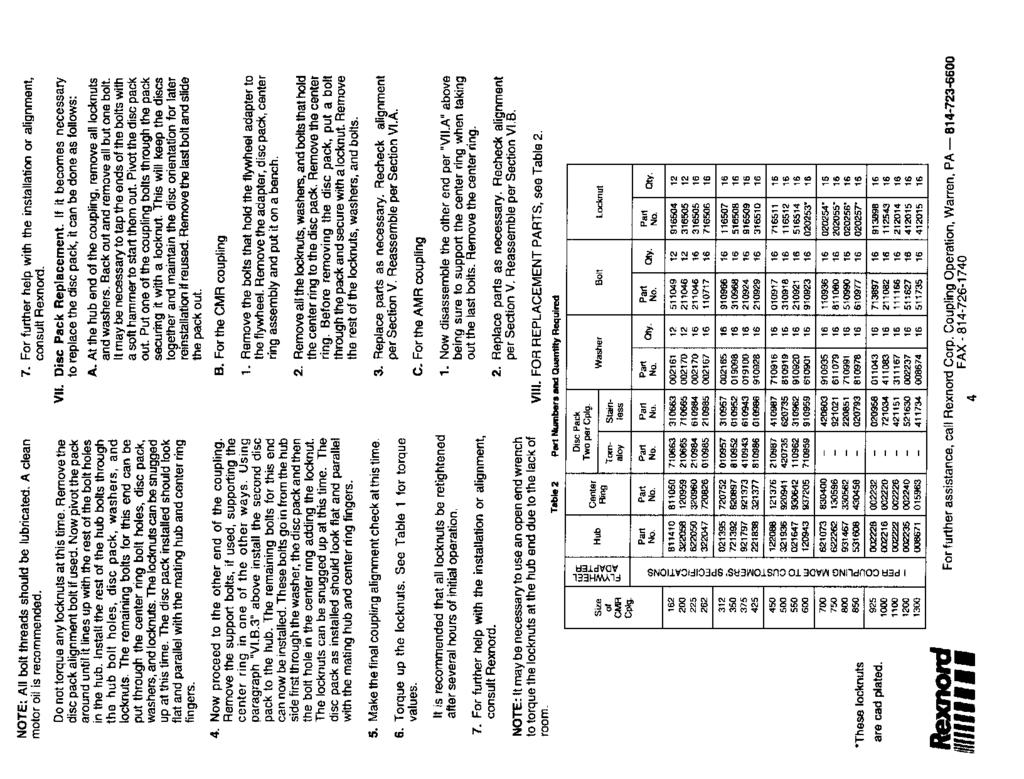
118 VILTER MANUFACTURING CORPORATION VILTER MultiCylinder Compressor Compressor (Mushroom Style) (cont d) All replacement parts are drilled. They are interchangeable with original parts. All replacement cylinder line kits have roll pins. Discard roll pins if new liner is being used with old safety head and safety head yoke. The old style frames have built-in guide lugs which serve the same purpose as the roll pins. Replace safety springs and cylinder covers on the compressor. NOTE: Compressors with serial numbers 7000 and higher have 4 holes drilled through the safety head and safety head yoke into the cylinder liner, to accommodate roll pins. After replacing the cylinder cover, return the unloader mechanism to its operating position by removing the metal rod from the hole in the frame. This allows the piston to rise. Put the plug back into the hole (hole B ) in the frame and reconnect the unloader lines , 450XL Compressor (Bullet Style) Before assembling the valves, safety head and yoke, use a solvent to remove any dye, paint or tape you may have used as a marker. Put the suction valve into their holes with the end that has two coils closely wound towards the bottom of the hole and twist with the top of the finger. This will lock the spring in its hole. The springs are properly installed when the safety head can be inverted without the springs falling out. Springs of all the same hand are used (wound the same way). This allows the valve to rotate during operation. When the valve rotates, the action tends to heal any small nicks or scratches on the valve or seal, and clean away any foreign material or dirt which may lodge between the valve and seat. This will also spread out the plate wear from the springs. Place the suction valve into its cavity in the cylinder liner with the top facing up. The valve plate should rotate freely without binding. Replace the safety head assembly in the frame. IV. COMPRESSOR DRIVE TYPES NOTE: Before proceeding, refer to Paragraph I, General Service Instructions. A. V-Belt Drive Compressors 1. Belt Removal Remove belt guard. Loosen motor rail clamps. Remove tension on belts to provide enough slack to allow the belts to be removed from the drive without having to pry or roll the belts off. If belts are to be reused, mark the belts to orientation on the drive. The belts can now be removed. 2. Flywheel Removal Remove flywheel screw holding the flywheel on the shaft. Install flywheel puller on the flywheel. An alternate tool can be fabricated from a 4½ ( mm) diameter steel plate, ½ (12.7 mm) thick with three equally spaced 11 / 16 (17.46 mm) holes on a 3½ (82.55 mm) or 3 7 / 8 (98.43 mm) bolt circuit. See Figure 4. Also needed are several 1¾ (44.45 mm) plate washers and three 5 / 8 (15.88 mm) x 1¾ (44.45 mm) long screws. Place several washers against the end of the shaft so they extend past the flywheel hub. 400 Series VMC 2/01 SERVICE Replaces all Previous Issues
119 VILTER MANUFACTURING CORPORATION VILTER MultiCylinder Compressor 2. Flywheel Removal (cont d) Screw the plate to the flywheel and tighten the screws so the plate pulls tight against the washers. Tighten the screws evenly so they pull the flywheel. Apply pressure until the flywheel breaks free. FIGURE Sheave Removal FLYWHEEL REMOVAL TOOL Specific instructions for motor sheave maintenance are located after the Operation Section of this manual. These should be consulted for specific maintenance instructions. 4. Drive Inspection 2 Dia. Inspect the motor and compressor shafts, sheave bushing and flywheel for fretting corrosion or other wear. Fretting corrosion is the result of two metallic surfaces (a shaft 5 Dia. and flywheel or bushing bore) having movement relative to one another. This is usually due to the incorrect tightening of drive components, use of oil or other anti-seize compounds, worn components, burrs or other imperfections not allowing the flywheel and crankshaft to mate properly. Signs of fretting corrosion are reddish brown powdery oxidation and wearing away of the surface of the shafts or drive component shaft bores. Minor fretting corrosion may be eliminated through light sanding after which the adequate contact area between the crankshaft and flywheel must be assured to prevent further fretting. Heavy fretting corrosion will require repair or replacement of the motor shaft or replacement of the compressor crankshaft and drive components. The flywheel or crankshaft should not be rematched to eliminate the results of the fretting corrosion, as adequate clearances cannot be assured after remachining. The drive keys should fit tightly in their respective grooves and be free of damage. The keyways should also be free of chips and burrs that would not allow full contact of the key to the keyway. The flywheel and sheave should be inspected for abnormal wear and damage. A groove wear gauge should be used to check condition of the sidewalls and width of the groove. Excessive wear is not permitted as this will lead to problems in achieving correct belt tension and loading, contributing to excessive belt and sheave wear. Clean any foreign matter that has accumulated in the grooves. The sheave and pulley should be inspected for cracks and other damage that could affect the integrity of the drive components. The sheave and pulley should be inspected for excessive run-out, indicating bent components. Bent pulleys or sheaves will wear the groove sidewalls unevenly, as the belt changes its angle of engagement as the pulley turns. 400 Series VMC 2/01 SERVICE Replaces all Previous Issues
 The groove bottom should also be checked for polishing, as this indicates the belt is not riding correctly in the groove.")

120 VILTER MANUFACTURING CORPORATION VILTER MultiCylinder Compressor 456XL Booster FIGURE XL High Stage UNIT BELTING REQUIREMENTS DUE TO HORSEPOWER 4. Drive Inspection (cont d) The groove bottom should also be checked for polishing, as this indicates the belt is not riding correctly in the groove. What has happened is the belt or groove has worn to the point the belt is actually rubbing on the bottom of the groove. This effectively changes the pitch diameter of the sheave or pulley for that groove, causing the belt to operate at a different speed than the rest. This will result in excessive heat and wear to the drive components. When drive components are replaced, it is necessary to replace them with identical components. Due to operating conditions and the horsepower requirements of the compressors, the number of belts on a compressor package can vary from 2 through 10 belts and not all flywheel grooves will be filled. also be inspected for sharp bends and kinks while they are slack as this indicates internal damage due to incorrect installation techniques. The belts can be cleaned at this time. Only soap and water should be used to clean the belts and other components. Belt dressing should never be used on drive components, as it will attack the elastomer used in construction of the belts. Belts should always be changed in sets to minimize length variations between used and new belts. Note the match numbers on the belts. The same number must be on all belts in the set. 5. Drive Installation If installation is new and the belts are being installed for the first time, the following items must be taken care of before the belts can be installed. Drive belts should be inspected for abrasion, tearing, separation or checking that would indicate possible damage to drive components or alignment problems. They should 400 Series VMC 2/01 SERVICE Replaces all Previous Issues
121 VILTER MANUFACTURING CORPORATION VILTER MultiCylinder Compressor 5. Drive Installation (cont d) The compressor, motor and base should be level. This will help speed the alignment process of the unit if the shafts are level and in the same plane before starting the alignment process. All piping must be finished and properly supported. Any piping stress must not be permitted to act on the compressor frame. The base must be secured to the floor and grouted. The compressor should be checked for a soft foot and shimmed accordingly. Elimination of a soft foot in a belt drive compressor is essential to reduce vibration and misalignment problems. The sheave and pulley should be checked for paint and foreign matter in the grooves. Any foreign material will cause a decrease in the horsepower transmitting ability of the belts and lead to accelerated wear of the belts, pulley and sheave. If this is an existing installation, the motor and compressor shafts should be checked to see if they are level and in the same plane before starting the alignment process. If the compressor has been moved or if there is a complaint of excessive vibration, the compressor should be checked for a soft foot. Absolutely no lubricants or anti-seize compounds should be used in the installation of the motor sheave and bushing, or the crankshaft and flywheel. The bushing as supplied by the manufacturer should not have any lubricant applied to it or the sheave bore. The applied lubricant will be trapped between mating surfaces of the sheave and bushing, or bushing and shaft. When the components are tightened, the resulting hydraulic pressure of the lubricant trapped between the mating surfaces will result in a cracked sheave or bushing. Lubricant or anti-seize is usually applied to the shaft for ease of disassembly. As the anti-seize is trapped when the parts are tightened, it will create a sliding layer between the parts. The parts are not free to move independent of each other while the unit is in operation, creating fretting corrosion. This results in excessive wear of the drive components and the possibility of the parts welding themselves together. The belts can now be installed. The motor should be moved towards the compressor to facilitate the installation of the belts. The belt closest to the compressor should be installed first. The belts should not be rolled or pried when installing them, as this will damage the cords in the belts and cause a failure in a short time. 6. Drive Alignment There are 3 different types of misalignment that are possible, more than one of which may be present at any one time. These are: Horizontal angular Vertical angular Parallel Although V-belt drives are somewhat tolerant to misalignment, the maximum amount of misalignment permitted is 1 / 16 of an inch per 12 of shaft, center to center distance. If this is exceeded, excessive drive, belt and bearing wear will result. Horizontal angular misalignment results when the motor and compressor shafts are in the same horizontal plane, but not in the same vertical plane. A straight edge is held against the compressor pulley face. The distance from the straight edge to the motor sheave sides is compared. They should be the same. If they are not the same, adjust the motor to bring the sheave and pulley into alignment. 400 Series VMC 2/01 SERVICE Replaces all Previous Issues
122 VILTER MANUFACTURING CORPORATION VILTER MultiCylinder Compressor 6. Drive Alignment (cont d) Vertical angular misalignment results when the motor and compressor shafts are in the same vertical plane, but not in the same horizontal plane. A straight edge is held against the compressor pulley face. The distance from the straight edge to the motor sheave at the top and bottom is compared. They should be the same. If the back of the motor is sitting low, the top of the sheave will be back further than the bottom of the sheave. The motor must be shimmed so the top and bottom of the sheave are in the same plane as the compressor pulley. The last check is the parallel alignment. This check aligns the belt grooves of the pulley and sheave. The measurement is taken from a straight edge held at the outer rim to the edge of the first groove used on the compressor pulley (usually not all grooves are filled due to horsepower requirements). This is then compared to a measurement taken from the straight edge to the corresponding groove on the sheave. The sheave position is then adjusted to assure the sheave is in line with the flywheel. 7. Belt Tension Proper tension is essential to long belt life. An improperly tensioned belt will result in inefficient operation and excessive heat. The ideal tension is the least amount of tension at which the belt will not slip under the load. 8. Single 5V, V-belts One device that provides the most accurate way of measuring the tension of the drive belts is a belt tension spring scale (Vilter Part No. 3072A). See Figure 6. This device measures the amount of force needed to deflect the belt a given amount. The range of the readings should be between 12 to 18 lbs. The deflection should be 1 / 64 per inch of span. If the span of the belts from the sheave to the flywheel is 38 inches, the amount of deflection should be 19 / 64 (7.54 mm) and the tension required to achieve it should be between 12 to 18 lbs. FIGURE 6. BELT TENSION SPRING SCALE The belt tension spring scale is placed in the center of the belt span. The scale is then pushed down until the proper deflection is reached. The tension should then be read and recorded. The process is then repeated for the remaining belts. If the tension is too low, the belts should be tightened evenly and rechecked. The tension between belts should be within ±1 lbs. of each other. Inconsistent measurements indicate problems with alignment, belt length and/or wear of the drive components. The problem should be corrected before the unit is returned to service. 9. Banded 5V, V-belts Due to their design, banded V-belts require special tensioning techniques in order to set the tension properly. There are two methods to check the tension of banded belts. They are as follows: The first method utilizes a tension tester to measure the deflection. The number of belt bands in the belt is multiplied by the deflection force of 12 to 18 lbs. A board or metal plate is then placed across the bands to equalize the force as the tension tester is depressed on the board or plate. 9. Banded 5V, V-belts (cont d) 400 Series VMC 2/01 SERVICE Replaces all Previous Issues
123 VILTER MANUFACTURING CORPORATION VILTER MultiCylinder Compressor A straight edge is positioned across the sheave and flywheel to use as a reference to measure the deflection of the belts. The second method measures the amount of stretch as the belts are tightened to determine the tension of the belts. The banded belts are installed on the drive and rotated to get all the slack on the bottom side. The belts are then tightened to remove the slack from the belts. Measure the outside circumference to the nearest ¼ (6.35 mm). Multiply this reading by ¾% (0.0075) to 1% (0.01). Add this to the circumference reading. Elongate the belt to the new length. EXAMPLE: 80 x 1% = = 80.8 B. Direct Drive Compressors 1. Coupling Removal Remove the guard. Remove the bolts that extend through the coupling and remove the center member. Remove the bolts that hold the shim packs to coupling, and make note of location of the washers. Using one or two of these bolts through the shim pack will keep the shims in alignment. To remove the coupling from the crankshaft, remove the screw (and washer, if present). Try to lightly tap the coupling off the shaft, or apply heat to coupling. A puller can be constructed out of a flat steel bar with holes that match two holes in the coupling in a straight line past the center of the crankshaft. Make a hole in the center of the bar for a 5 / 8 (15.88 mm) bolt, thread the hole or weld a 5 / 8 (15.88 mm) nut inline with the hole. Bolt this bar loosely to holes in coupling. Place a solid washer or disc (a little smaller than end of the shaft) between the bar and in front of the tapped hole in the crankshaft. Using a 5 / 8 (15.88 mm) bolt, apply force to center crankshaft and a pulling force on the coupling. Inspect the compressor coupling bore and crankshaft to make sure they are clean and free of burrs. Apply anti-seize to shaft and coupling bore. Place the key on the shaft and slip on the coupling. Install the bolt (and washer, if required), and tighten. Reassemble shim pack and center member in correct orientation. Tighten bolts and note distance between hubs per coupling manufacturer s bulletin. This bulletin is located in the Installation Section. Recheck alignment, if necessary. V. CAPACITY CONTROL A. Old Style (Mushroom Type) 1. Lift Pins, Ring and Springs Removal The valve lifting mechanism consists of the lift pins, lift ring and lift springs all assembled to the cylinder liner. To remove these parts from the cylinder liner, place the liner on a flat surface in an upright position. Rotate the lift ring slightly until the four semi-circular notches line up with the lift pins, and slide the ring down off the liner. Lift the pins out of the top of the liner. In order to put the unloading mechanism onto the cylinder liner, set the lift ring on a flat surface with the guides for the lift springs facing up. Next place the cylinder liner inside the lift ring. Drop the four lift pins into their holes in the liner with the notched ends of the pins facing down and the flat side facing out. Lift the rings so the semicircular notches slide over the pins. Then, rotate the lift ring so the springs fit into their holes in the cylinder liner. 2. Coupling Replacement 400 Series VMC 2/01 SERVICE Replaces all Previous Issues

124 VILTER MANUFACTURING CORPORATION VILTER MultiCylinder Compressor Use this illustration for: Oil Actuated Unloading High Stage Booster Both Stages of 2-Stage Gas Actuated Unloading High Stage High Stage of 2-Stage * Yoke assembly is bolted down on one end as shown on the two cylinder and two-stage compressor capacity control mechanism. All other compressors do not use these bolts. FIGURE 7. TYPICAL CAPACITY CONTROL MECHANISM ARRANGEMENT 440 COMPRESSOR (OLD STYLE MUSHROOM TYPE) 400 Series VMC 2/01 SERVICE Replaces all Previous Issues
125 VILTER MANUFACTURING CORPORATION VILTER MultiCylinder Compressor 2. Actuator Mechanism Removal The first step of removing capacity control actuator from the machine is to push the unloader piston down with a block of wood. This holds the assembly depressed and makes handling much easier. Push the assembly away from the unloader piston until the notch in the yoke lifting arm slides free of the flats on the long pivot pin. Then, remove the mechanism through the liner hole in the top of the frame. Remove the long pivot pin from the shaft of the piston. Now slide the piston out of the cylinder and slip the ring or rings off the piston, taking care not to break any. NOTE: Gas actuated unloader pistons have two grooves and use four metal piston pins. Oil actuated unloader pistons have one groove and use a rubber piston ring (o-ring). 3. Actuator Mechanism Replacement Gas actuated unloader piston: Clean the piston thoroughly and place four steel rings in each groove. Work the rings in carefully. Avoid breaking them. Place the piston in the cylinder and compress the rings to work them into the cylinder. Oil actuated unloader piston: Clean the piston thoroughly and place the o- ring on it. Work the o-ring on carefully to avoid breaking or excessively stretching it. Liberally coat piston and o-ring, as well as cylinder bore, with compressor oil. Place the piston in the cylinder and compress the o- ring to work it into the cylinder. the rear of the lifting rod. This keeps the yoke depressed for easier handling. Place the yoke into the frame through the cylinder opening and position it so the slot on the yoke lifting arm registers with the flats on the long pivot pin. Depress the piston with a block of wood, and remove the rod or piece of wood used to hold the yoke assembly depressed. Then, center the assembly between the two cylinder liner holes. B. New Style (Bullet Type) 1. Lift Pins, Ring and Springs Removal In order to put the unloading mechanism back in the cylinder liner, place the lift pins with the springs around them in their holes. Place the lift ring on the pins with the smaller inside diameter facing top of the liner so it will slip over and cover the retainer when it is in place. Placing the liner on its side and holding the lift ring back against the pins and springs, slide the ring retainer over the liner into its groove. 2. Unloader Piston Removal It is not necessary to remove or disturb the actuator mechanism or the cylinder liners to remove the unloader piston. There are two holes in the top of the unloader piston. One is threaded, the other is not. Use ¼ -20NC eyebolt in the center hole. Use the other hole to keep the piston from turning in the hole in the frame while doing this. Using the eyebolt as a handle, pull the piston out of its hole in the frame. Next, insert the long pivot pin into its hole in the piston shaft and position it so the flats will receive the slot of the yoke lifting arm. The end of the pin is machined flat so the installer can see the position of the inner flat. Compress the yoke assembly and place a piece of 5 / 16 (23.81 mm) o.d. steel rod under 400 Series VMC 2/01 SERVICE Replaces all Previous Issues

126 VILTER MANUFACTURING CORPORATION VILTER MultiCylinder Compressor ** COMPRESSOR APPLICATION NOTE Gas Actuated Unloading is standard on: High Stage, except 100% internal CR Oil Actuated Unloading is standard on: High Stage with 100% internal CR Booster Both Stages of integral 2-Stage ** Yoke assembly is bolted down on one end, as shown, on all compressor banks equipped with optional single cylinder unloading. All other compressors do not use these bolts. FIGURE 8. TYPICAL CAPACITY CONTROL MECHANISM ARRANGEMENT 450 & 450XL COMPRESSORS (NEW STYLE BULLET TYPE) 400 Series VMC 2/01 SERVICE Replaces all Previous Issues
127 VILTER MANUFACTURING CORPORATION VILTER MultiCylinder Compressor 3. Unloader Piston Replacement Before reinstalling piston, remove old ring set. Clean and inspect for wear. Replace piston if wear is excessive. a ring set consisting of PTFE outer ring and a silicone rubber inner ring is used on the piston. Replace ring set carefully with a new one every time a piston is removed. With eyebolt removed, place the piston into its hole in the frame. Compress the rings with the fingers and work them into the hole carefully so they are not nicked or cut as the piston is moved down. Push the piston down until it touches the yoke lifting arm. center the mechanism between the two cylinder liner holes. VI. SAFETY VALVE (INTERNAL RELIEF) A. Removal If, for any reason, the safety valve has relieved, install a new valve. Make no attempt to adjust the relief valve. To replace the safety valve, remove the cover on the top of the compressor frame marked safety valve by taking out the two screws which hold it in place. Then, remove the safety valve by using a standard 1¾ (44.45 mm) socket. 4. Actuator Mechanism Removal Before a capacity control actuator mechanism can be removed from the compressor, at least one of its corresponding cylinder liners must be removed. The first step in removing capacity control actuator from the machine is to push the unloader piston down with a block of wood. Then take a piece of steel ( 5 / 16 in diameter) or a piece of wood, and insert it between the two vertical rods on the yoke assembly accommodating the short pivot pin and fulcrum pin. This will hold the assembly depressed and make handling much easier. Then remove the unloader piston as detailed above. The mechanism can then be removed through the cylinder liner hole in the frame. 5. Actuator Mechanism Replacement Compress the yoke assembly and place a small piece of wood or a 5 / 16 (7.94 mm) o.d. steel rod between the two vertical rods mentioned in paragraph 4. This keeps the yoke depressed for easier handling. Then place the mechanism into the frame through the cylinder liner opening and position it. Install unloader piston as detailed above. Depress the unloader piston with a block of wood and remove the rod or piece of wood used to hold the yoke assembly depressed. Then Note: Safety Valve is set at a differential pressure of 300 PSIG (2069 kpa). Maximum discharge temperature is 300 F (150 C). FIGURE 9. B. Replacement SAFETY VALVE LOCATION Lightly oil the threads of the valve and screw the valve into place. Lightly oil a new gasket and place it on the frame. Position the cover and tighten it down. 400 Series VMC 2/01 SERVICE Replaces all Previous Issues
128 VILTER MANUFACTURING CORPORATION VILTER MultiCylinder Compressor VII. OIL PRESSURE ADJUSTMENT ASSEMBLY A. Disassembly The oil pressure adjustment assembly is located in the front bearing housing. It consists of a spring loaded ball positioned in a machined seat in the top of the front bearing housing. An adjusting screw turned in and out changes the amount of oil bypass, thus changing the oil pressure. Remove the cap. A packing tool is required to remove the gland nut (Vilter Part No. A33781A). After the gland nut has been removed, use a large screwdriver to turn the stem counterclockwise and remove it completely. The packing with 2 washers should also come out. Using a pencil magnet, pull out the spring and steel ball. B. Reassembly Clean the steel ball and place in the hole. Place the stainless steel spring on top of it. Screw the adjustment stem in the hole to get threads started. Place a washer over the end, then packing, then the other washer. The adjustment stem may have to be turned in so the packing nut can be installed and tightened. Adjustments of the oil pressure will have to be reset after start up. Replace the cap and gasket afterwards. C. Adjustment To provide quick response of the compressor unloader mechanism, it is recommended the oil pressure relief valve be set to maintain 40 psi ( kpa) net oil pressure. Net oil pressure should be held at 35 psi ( kpa) and 40 psi ( kpa). Net oil pressure is calculated by subtracting the compressor suction pressure from the oil pressure gauge reading while the compressor is running. NOTE: Before proceeding, refer to Paragraph I, General Service Instructions. A. Removal To remove the oil filter, drain the tank by removing the pipe plug on the bottom or side. Next remove one of the front screws. It can then be threaded back in at least 2 turns, or a ¼ (6.35 mm) longer screw can be used and also threaded in 2 turns. This will be the pivot point or hinge to swing the filter and tank out for ease of removal. By unscrewing the remaining 3 screws alternately, the tank will start to lower until the first screw installed comes in contact with the filter adapter. Force the center tube top plate down and out of its connection hole while pivoting the filter tank. Now that the filter and center tube can be removed, disassemble the center tube by removing the bottom spring plate. Slide the old filter off and discard properly. The tube should be washed off and clean. B. Replacement Make sure to remove the used gasket of the filter adapter and install a new one. After cleaning the tank, reinstall the pipe plug in the drain. Install it on its pivot screw. Add fresh oil to fill half the tank. Reassemble the new filter on the center tube. Slowly place the filter in the tank and allow the filter to absorb the new oil. Pivot the tank under the adapter and align the center tube in its hole. Start the remaining 3 screws than tighten the tank flange to the adapter. The proper placement of the mechanism, once in the frame, is having the curved sides of the bottom plate on the mechanism aligned between the lower liner bores. VIII. TRI-MICRO OIL FILTER 400 Series VMC 2/01 SERVICE Replaces all Previous Issues
129 VILTER MANUFACTURING CORPORATION VILTER MultiCylinder Compressor IX. OIL PUMP ASSEMBLY NOTE: Before proceeding, refer to Paragraph I, General Service Instructions. A. Removal To remove the oil pump assembly, first remove the filter tank and adapter from the rear housing. Be prepared for a small amount of oil to drain from adapter. The pump will be exposed in the center and the outer pump housing will be covered by a gasket. Remove gasket. At the top right and bottom left, you will find tapped holes to aid in removing the pump, if necessary. The pump housing is approximately 1½ (38.1 mm) thick, so it requires jack screws 2 (50.8 mm) or longer to release the inner gasket. Once loose, pull the oil pump straight back. The oil pump is a factory built and tested component. It is furnished as a complete assembly only and cannot be serviced in the field. B. Replacement To replace the oil pump assembly, first rotate the crankshaft so the drive key is hanging from one of four screws through the rear bearing retainer. Make sure the small orifice plug in the rear housing (at the 12 o clock position) is clear. Clean all gasket surfaces. Install gasket (Vilter Part No A), correctly aligning oil passage holes. Align pump shaft flats to match flats in pump drive key. The locating dowel pin in the rear housing should align with hole in the pump housing to the top-left-center. Install the pump and seat it against the inner gasket. The outer surface of the pump should now be recessed approximately 1 / 8 (3.175 mm) to the rear bearing housing. Install gasket (Vilter Part No A), correctly aligning the holes. The slot in this gasket should be at the 9 o clock position. Place the rubber seal gasket on the filter adapter, and reattach the filter assembly onto the rear housing. Install screws and tighten down evenly. X. PREPARATION FOR INTERNAL SERVICING NOTE: Before proceeding, refer to Paragraph I, General Service Instructions. A. Handhole Cover Removal To work internally on the compressor, the handhole cover and crankcase oil will have to be removed to gain access. The heater will have to be electrically disconnected at this time. Remember to shut the power off and lock it out. After disconnecting the wiring, loosen all but two screws on the upper corners of the cover. This helps support the cover during removal and prevents damaging the heater. If the cover sticks to the frame, a slight tap with a lead or soft face hammer will free it. Holding the cover in place, remove the two remaining screws, and pull the cover straight back away from the frame. Remove any gasket material from the cover and frame face. Also inspect and remove any burrs or rough edges from the mating surfaces to ensure a tight seal at time of reassembly. B. Handhole Cover Replacement Lightly lubricate both sides of a new gasket with refrigerant oil or general purpose grease. Place the gasket on the cover, and guiding in the heater, place the cover against the frame opening. While holding the cover and making sure the gasket is still in place, insert two screws in the lower row to help support the cover and keep the gasket from slipping out. Start the rest of the screws in their holes and continue to check gasket placement. Tighten screws evenly to the torque requirements in Table 2, 3 or 4 (depending upon compressor model). Connect the B. Handhole Cover Replacement (cont d) 400 Series VMC 2/01 SERVICE Replaces all Previous Issues
130 VILTER MANUFACTURING CORPORATION VILTER MultiCylinder Compressor heater wiring and heater cover, add oil to crankcase and turn on power to the heater to preheat the oil for operation of compressor. XI. CRANKSHAFT SEAL NOTE: Before proceeding, refer to Paragraph I, General Service Instructions. A. Oil Seal Leakage In refrigeration compressors, a slight amount of oil leakage past the crankshaft seal is normal and desirable. A few drops per minute is reasonable. This leakage performs two important functions. It helps lubricate the neoprene bellows and o-rings, and it helps cool mating rotating parts to provide less wear and longer life. A receptacle for collection is recommended. B. Removal The flywheel or coupling will have to be removed. Detach the tubing line on the bottom of the front housing. Oil will drain from the seal chamber, be prepared to collect it. After the oil has drained, remove the 8 screws holding the cover. When removing the cover, caution should be taken because the front carbon seal might come off with the cover. At this time, if the seal is going to be reused, clean the surface of the shaft and avoid getting anything in the housing area. Grab the front rubber bellows and pull forward. It should release. If not, pry by the tabs on the metal ring (alternating force from side to side) to remove it. Remove the large spring. Next step is to remove the 3 screws in the retainer that hold the inner mirror seat. Put 2 of these screws in the tapped holes of the retainer. Rotate the retainer so screws are at 3 and 9 o clock positions. Pull on the screws to aid in removing the retainer and the rest of the seal assembly. Clean out the seal chamber with suitable refrigeration parts cleaner. Afterwards, coat the area and crankshaft to keep them from rusting. C. Installing A New Shaft Seal Remove the mirror seats from the inner retainer and outer cover. The mirror face can be removed by tapping on back side that is exposed in each part. Make sure these parts are then cleaned. Place either on a flat surface with the recess up. Oil the o-ring sealing area. Take the mirror face (do not touch the mirrored surface), oil outer o-ring and lay it in the cover or retainer with the mirror face upward. Using a very clean cloth or similar item, cover mirror face and, using palm of hand, set it in the recess. Repeat this assembly process for the other mirror face. Vilter recommends that if any part of a seal needs replacement, the entire shaft seal should be replaced with a new one. Make sure the oil passage in the shaft is unobstructed. Install the inner retainer with mirror face, flush in front housing, with the word TOP at the top. Tighten down evenly with the 3 screws. The shaft seal assembly is symmetrical. It can be installed in either direction. Spray oil on inner mirror face. Liberally coat oil on one of the bellows and carbon assemblies. Avoid coming in contact with carbon. Carefully slip the assembly on the shaft until the carbon touches the mirror face. Put the spring over the shaft and seal on the bellows assembly, and slide it onto the shaft to join up with the spring. With the new cover gasket in place, install the cover over the end of the shaft. Push the cover all the way on, lining up the bolt holes so the drain is to the bottom. Tighten down the 8 screws evenly to the torque requirements in Table 2, 3 or 4 (depending upon compressor model). XII. CONNECTING RODS AND PISTONS NOTE: Before proceeding, refer to Paragraph I, General Service Instructions. 400 Series VMC 2/01 SERVICE Replaces all Previous Issues

131 VILTER MANUFACTURING CORPORATION VILTER MultiCylinder Compressor A. Disassembly After the cylinder covers, valves and handhole cover have been removed, the first step in removing the piston and rod assembly is to remove the Palnut locknuts on the rod bearing bolts. Then, remove the plain nuts and slide the bearing cap off of the nuts. The Palnut locknut is not used with this type of locknut. Handle the bearing cap carefully to avoid damage to the bearing half insert. Push the rod and piston out through the top of the cylinder. Avoid possible mixing with components. Keep all parts together in relation to their position in the compressor. Connecting rods and rod caps are match marked to aid in reassembly. On reassembly, all parts must be installed in the same position in the compressor. As soon as the parts are removed from the compressor, they should be thoroughly cleaned with a suitable refrigeration parts cleaner. Once the oil film is removed, the bare metal is subject to rust. This reaction can start immediately. Therefore, lubricate the surfaces of the parts lightly with clean compressor oil immediately after cleaning XL VMC Compressor Only If the piston rings are to be removed, wrap a piece of thin shim stock around the piston. Work the rings carefully out of their grooves and onto the shim stock. They can then be worked down over the piston. Caution must be exercised to prevent breaking the rings. The piston and connecting rod assembly should not be disassembled further. It is furnished only as a complete assembly and should not be worked on in the field. B. Reassembly All new compressors use three compression rings and one oil control ring. When replacing rings, use the ring expander. Check the grooves to make sure they are clean. The tabs on the bearing half insert fit into the recess in the rod and rod cap, and the inserts can be slipped out without difficulty. To replace the rod bearings, it is necessary to change the inserts only and not the entire rod & 450 VMC Compressors Only To remove the rod from the piston, take out the piston pins. Remove the spring locks from the pin hole on each side of the piston and slide out the pins. If this cannot be accomplished by hand, it may be necessary to force the pin out with a brass rod and hammer. Be careful not to damage spring lock grooves. To remove the piston rings, use the ring expander. Caution should be exercised to prevent the rings from scoring the piston. FIGURE 10. PISTON RING COMPRESSING TOOL 400 Series VMC 2/01 SERVICE Replaces all Previous Issues
132 VILTER MANUFACTURING CORPORATION VILTER MultiCylinder Compressor B. Reassembly (cont d) The easiest way to replace the rings on the piston is to wrap a thin piece of shim stock around the pistons and slide the ring over this. Do not force the rings when sliding them onto the shim stock. The rings are brittle and may snap. A tool is also available to aid in the installation of the rings. Both compression and oil rings are marked to indicate the top of the ring. Install the compression rings with the identifying mark to the top of the pistons. Rotate the end gaps on each ring so they are not aligned on the piston. Remove the piston assembly. Check the fit of the piston pin bushing for wear. The 440 and 450 have a different pin and piston design from the 450XL compressor. The 440 and 450 piston and piston pin bushing have a slip fit. When replacing the piston and bushing, the bushing must be reamed to the correct slip fit after installation into the rod to accommodate the new piston pin. The 450XL piston and piston pin bushing cannot be changed in the field due to tolerances. They must be purchased as a unit with the connecting rod and piston assembly. The piston pin should not slip easily into its hole, but it must not be driven down. It may be necessary, however, to tap the pin lightly with a block of wood and a hammer. Be sure the hole in the rod pin bushing is aligned so the pin can slip through it. When the pin has been tapped in far enough, install the two piston pin lock rings, one at each end of the piston pin. The bearing inserts should never be spread open, by hand or any other means, to provide for a tighter fit in the rod. If an inspection indicates the rod bearing surfaces are worn, replace the bearing insert. Assemble bearing inserts by pressing them into place, making sure the notch in the rod is clear. If the bearing insert does not properly fit in the rod and it falls out during assembly, either the bearing insert or the rod is worn or incorrectly made. When installing the bearing insert into the connecting rod, make sure there is no oil on the connecting rod or the back side of the bearing insert. If the original bearings have failed, check the crankshaft bearing surface. If there are slight imperfections due to bearing failure, remove by polishing with fine crocus cloth. Then, clean the bearing surface with suitable refrigeration cleaner and lubricate with clean compressor oil. Lubricate the inside of the cylinder and the entire piston. The recommended method of installing the piston in the liner is with the use of a Piston Ring Compressor. See Figure 10. Attach the oil line to the bottom of the front housing. Do not over tighten the nut. Rotate the shaft a few times to help the seal settle into position. Two styles of bearing half inserts have been used in the compressor. One style has only the hole in the rod half to allow oil to travel up the rod. The second type has annular grooves to allow a continuous supply of oil. FIGURE 11. FRONT COVER ASSEMBLY AND DISASSEMBLY STUD CAUTION 400 Series VMC 2/01 SERVICE Replaces all Previous Issues

133 VILTER MANUFACTURING CORPORATION VILTER MultiCylinder Compressor FIGURE 12. CRANKSHAFT SEAL ASSEMBLY 400 Series VMC 2/01 SERVICE Replaces all Previous Issues
134 VILTER MANUFACTURING CORPORATION VILTER MultiCylinder Compressor B. Reassembly (cont d) Connecting rod bolts are secured with one plain steel nut and one spring steel locknut (commonly referred to as a Palnut ). The plain nut tightening torque should be listed in Table 2, 3 or 4 (depending upon compressor model). The torque wrenches should be set to the high side of the tightening torque range. As the rods, bearing inserts and crank pins are all machine to fine tolerances, no further adjustments are necessary. locking feature is lost and a loose rod connection may result. After each rod is installed, rotate the crankshaft by hand to make sure everything is free and there is no binding of the rotating parts. CAUTION Late model VMC compressors may push liners out. XIII. CYLINDER LINERS NOTE: Before proceeding, refer to Paragraph I, General Service Instructions. A. Removal FIGURE 13. PISTON RING DIMENSIONS TABLE 1. PISTON RING DIMENSIONS AND TOLERANCES DIMENSION COMPRESSION OIL RING RING A B to to C to to D to to E to to After a plain nut has been placed on a rod bolt and torqued to the specified value, turn a Palnut to the rod bolt with the open end of the hexagon pointing away from the plain nut. The Palnut should be turned until mating parts are pulled together and actual tightening begins. Final tightening and locking is then achieved by giving the Palnut an additional 1/3 to 1/2 (maximum) turn. Although the plain steel nuts may be reused, new unused Palnuts must be used each time the connecting rods are reassembled to the crankshaft. If used Palnuts are installed, their Once the piston and rod assemblies are removed, the liner can be extracted from the frame by means of a Vilter Liner Pulling Tool (KT 257). This tool, or similar, is required for all 440/450 compressors and 2-stage compressors. NOTE: If the cylinder bank has unloading, the unloader piston needs to be held down for ease in liner removal. The liners in the 450XL compressor have a looser fit into the frame. They can be removed by pulling from the bottom of the liner by hand. NOTE: 2-Stage liners have an extra groove without ring that seals the suction chamber from the crankcase. 400 Series VMC 2/01 SERVICE Replaces all Previous Issues
135 VILTER MANUFACTURING CORPORATION VILTER MultiCylinder Compressor B. Lift Rings For Unloading There are two styles of unloading lift ring assemblies Lift Ring Assembly Rotate the lift to align the notches with the pins. The springs will follow. The lift ring will then drop to the bottom of the liner. Note the position of each lift pin. They will have to be returned to that position for reassembly. Push the lift pins up and out of the top of the liner to remove them. B. Installation Of Liners Before the liner is installed, make sure the outer surface of the liner is clean and the seat area in the frame is free of foreign matter. If a new o- ring is required, lubricate the o-ring and frame seating area with refrigeration oil. Slide the liner into the frame and align with the bore. Roll pin on the top of the liner can be orientated so if an imaginary line is drawn to opposite pins, it forms the letter X. Seat the liner in the frame recess firmly by use of Vilter Cylinder Liner Tool (Vilter Part No A). A similar tool can be constructed. Be sure to protect the liner lapped seats to prevent damage. The assembly of the lift ring is the reverse order of disassembly. Place the lift ring on a flat surface with the notches facing up. Put the liner in the center of the ring, and place a spring on each roll pin in the ring. Install a lift pin in each of the 4 slots along the outside of the liner. The flat on the bottom of the lift pin should be flush to the diameter of the liner. Lift the ring up the liner, and engage all four lift pin slots in the notches on the ring. Rotate the ring so the four springs engage in the holes of the lift ring stop /450XL Lift Ring Assembly Invert the liner and place on a flat surface. Locate the notched end of the snap ring that retains the lift ring, while pushing down on the lift ring in this area. Pry the snap ring out of its groove and continue all the way around the liner. Remove the snap ring, and slide the ring up and off the liner. Now the 8 pins and springs can be removed from the liner. Reverse the procedure to install a lift ring assembly on any 450/450XL liner. FIGURE 14. FIGURE 15. CYLINDER LINER ASSEMBLY TOOL CYLINDER LINER REMOVAL TOOL XIV. CRANKSHAFT 400 Series VMC 2/01 SERVICE Replaces all Previous Issues
136 VILTER MANUFACTURING CORPORATION VILTER MultiCylinder Compressor A. General Removing the crankshaft from the compressor is basically the same for all units, regardless of size. Because of a center bearing on all 12 and 16 cylinder compressors and the radius the 8 cylinder throws on the crankshaft, an extra step must be taken. A crankshaft may be removed from either end of the compressor. It is, however, easier to take the crankshaft out of the drive end of the frame. If the crankshaft is taken out of the pump end, the entire shaft seal must be removed. B. Removal From Drive End Remove any connections that will hinder the removal of the front bearing housing. When disconnecting the front oil line, be prepared to catch approximately 1 gallon of oil. Remove the shaft seal and inner retainer. Replace the two 5 / 8 (15.88 mm) x 4 (101.6 mm) socket head screws with threaded studs to support the front housing during removal. Remove the 6 5 / 8 ( mm) x 2 (50.8 mm) cap screws that hold the housing to the frame. Using the 4 (101.6 mm) socket head screws, insert them into the tapped holes on both sides of the housing to aid in the removal of the front housing from the frame and off the front bearing. During this process, the housing will have a tendency to hang-up on the outer diameter of the bearing, thus pulling the entire shaft with it and possibly disengaging from the rear housing. Care must be taken to prevent this from happening. While the front housing is being removed, push on the crankshaft to be sure it is staying in the rear housing. On a 458XL and 4516XL compressor, the rear housing will have to be removed, because the radius of the counterweight is larger than the radius of the front housing bore. Thus, the shaft will be hindered from coming straight out of the frame. On a 12 or 16 cylinder compressor, the center bearing must be freed. At this time, remove the oil circuit piping tee in the middle of the oil cooler side on the frame. Slip out the spring behind the tee with a piece of wire. Secure a ½ -13NCx10 long rod. Screw this into the threads in the end of the oil feed connector tube. Remove the tube from the frame with a slight pull on the rod. After the tube is taken out, separate the nut from the taper pin in the center bearing and tap the pin out of its hole. This releases the center bearing and allows the crankshaft to be removed. Once the front housing is removed, the crankshaft should be blocked from inside the frame due to its weight. Adjust the blocking as the work proceeds so the crankshaft does not bump the front bore nor make any contact with the journals. To aid in removal, a simple step can be added. Before removing the shaft from the rear housing, remove the rear bearing retainer and tap the center hole to 1¼ (31.75 mm) NPT. Reinstall the retainer on the end of the crankshaft. A 1¼ (31.75 mm) pipe can be threaded into it and used as an extension bar for handling the crankshaft during removal. C. Removal From The Pump End To pull the crankshaft from the pump end of the compressor, remove the pump cover filter adapter, the complete oil pump assembly and the rear bearing housing. The crankshaft does need to be blocked to prevent damage and on 12 and 16 cylinder compressors, the center bearing needs to be freed. The shaft seal cover, shaft seal, and inner retainer will also have to be removed. All special notes apply to this method as well. D. Servicing The Center Bearing (12 & 16 Cylinders) The center bearing on this compressor is a split sleeve type bearing much like connecting rod bearings. To disassemble the bearing, remove the four bolts holding the halves of the center 400 Series VMC 2/01 SERVICE Replaces all Previous Issues
137 VILTER MANUFACTURING CORPORATION bearing housing together. The bearing inserts are snapped into place and can readily be removed by pushing them out by hand. Clean the bearing housing thoroughly before installing new inserts. Snap the inserts into place. Lubricate the bottom half with refrigeration oil, and position it on the crankshaft. Do the same to the upper half, and locate it using the dowel pins provided. When aligned, bolt the halves together and tighten with a torque wrench to the values listed in Table 2, 3 or 4 (depending upon compressor model). NOTE: If oil dams are present on the center housing, they will need to be reinstalled if only changing the insert bearing. The current center housing does not require these dams. E. Reinstallation Whichever method was used to remove the crankshaft, extreme care is needed when placing the shaft back into the frame. Avoid any damage to the journals, and block the crankshaft once in position. If the crankshaft was removed from the front end and the rear housing left in place with the oil pump, it is imperative the locating pin on the rear bearing align with the slot in the bottom of the rear housing bore. Also, the pump drive key must engage with the pump shaft. If the unit is 12 or 16 cylinder, the center bearing must be guided into place. Align the hole in the bearing housing (for the oil feed connector tube) with hole in the frame. Screw the oil feed connector loosely on the end of the ½ (12.7 mm) threaded rod, and insert it into the hole. Push the tube into the bearing housing. Unscrew the rod from the tube. Place the spring in the hole and screw in the tee. Use thread sealant. Insert the taper pin it its hole. After placement, pin must be tightened. This expands the bearing housing so it fits tightly in the frame for quiet operation. VILTER MultiCylinder Compressor 400 Series VMC 2/01 SERVICE Replaces all Previous Issues
138 VILTER MANUFACTURING CORPORATION VILTER MultiCylinder Compressor MODIFICATION TO FRONT BEARING RETAINER AND FRONT BEARING COVER AFTER COMPRESSOR SERIAL NUMBER COMPRESSOR ONLY Compressors below serial number were furnished with the front bearing cover assemblies A30294A (no longer available) for 2, 4, 6 and 8 cylinders, A32162A for 12 and 16 cylinders; front bearing retainer 38115A for 2, 4, 6 and 8 cylinders; or 33500A for 12 and 16 cylinders (without the oil hole). Former front bearing retainers (31885A or 33500A) without oil holes cannot be used with current bearing cover assemblies A36240A and A36241A. There is no provision for oil to get to the bearings. If front bearing cover is being replaced, a current front bearing retainer must be ordered also, unless one of these current styles is already being used. If a current front bearing retainer is used with former style cover having an oil hole, remove orifice in cover and replace with solid 1 / 8 (3.2 mm) flush pipe plug. SEE SKETCH BELOW FOR LOCATION AND DESCRIPTION OF OIL HOLE IN CURRENT BEARING RETAINER. TOP STAMPED ON THIS SURFACE. 45 OIL HOLE 3 / 16 DIA. ¼ DEEP DIA. THRU ON VERTICAL CENTERLINE FIGURE 16. RETAINER PARTIAL VERTICAL CROSS SECTION 400 Series VMC 2/01 SERVICE Replaces all Previous Issues
139 VILTER MANUFACTURING CORPORATION VILTER MultiCylinder Compressor TABLE 2. TORQUE SPECIFICATION VMC MODEL 440 ITEM NO. VPN BOLT SIZE GRADE REQUIRED TORQUE APPLICATION L 5 / 8 x 3½ 2 95 Ft. Lb. Head Bolt with H2O Jacket G 5 / 8 x 2½ 2 95 Ft. Lb. Head Bolt without H2O Jacket C 5 / 8 x 1½ 2 95 Ft. Lb. Suction Screen Cover D 5 / 8 x 1¾ 2 95 Ft. Lb. Suction Screen Cover E ½ x 1½ 5 75 Ft. Lb. Suction Screen Cover D ½ x 1¼ 5 75 Ft. Lb. Suction Screen Cover E 5 / 8 x Ft. Lb. Safety Valve Cover E ½ x 1½ 5 75 Ft. Lb. Handhole Cover B 20 Ft. Lb. Cap, Valve B Plug, ¼ Hex. Pipe Plug 20 Ft. Lb C Plug, 3 / 8 Hex. Pipe Plug 35 Ft. Lb E 5 / 8 x Ft. Lb. Front Bearing Cover E 5 / 8 x Ft. Lb. Front Bearing Cover Q ½ x Ft. Lb. Front Bearing Retainer F ½ x 1¾ 5 75 Ft. Lb. Shaft Seal Cover ¼ dia. X 18 Td/in. Bearing Locknut G 5 / 16 x 1½ 2 11 Ft. Lb. Rear Bearing Retainer D 5 / 16 x Ft. Lb. Rear Bearing Retainer D (See Item 243) E ½ Nut 2 50 Ft. Lb. Center Bearing Support- Half Bolt (Used on Item 236 ½ x 1 ¾ Bolt VPN 11396D) F 9 / 16 Nut 2 65 Ft. Lb. Center Bearing Tapered Pin A 1 x 1 7 / Ft. Lb. Flywheel Hub E ¾ Hex Socket Pipe Plug 75 Ft. Lb G 7 / 16 x Ft. Lb. Oil Filter Shell E 5 / 8 x Ft. Lb. Rear Bearing Cover F ½ x 1¾ 5 75 Ft. Lb. Oil Pump Cover E Same as F Same as D 3 / 8 x 1 20 Ft. Lb. Yoke Assembly A 3 / 8 x 24 Nut 8 * Conn. Rod Cap A 3 / 8 Palnut * Conn. Rod Cap w/nut Lock B 3 / 8 Locknut 5 25 Ft. Lb. Discharge Valve Retaining 510A 1472A 3 / 8 Locknut Ft. Lb. Discharge Valve Retaining A 3 / 8 x 1 3 / Ft. Lb. Use with 510A B 3 / 8 x 1½ Ft. Lb. Use with 513 NOTE: * Refer to Connecting Rod Nuts Tightening Instructions VMC Compressors on page Series VMC 2/01 SERVICE Replaces all Previous Issues
140 VILTER MANUFACTURING CORPORATION VILTER MultiCylinder Compressor TABLE 3. TORQUE SPECIFICATION VMC MODEL 450 ITEM NO. VPN BOLT SIZE GRADE REQUIRED TORQUE APPLICATION L 5 / 8 x 3½ 2 95 Ft. Lb. Cylinder Head C 5 / 8 x 1½ 2 95 Ft. Lb. Suction Screen Cover 13152D 5 / 8 x 1¾ 2 95 Ft. Lb. Suction Screen Cover 13153E ½ x 1½ 5 75 Ft. Lb. Suction Screen Cover E ¾ Hex. Pipe Plug 75 Ft. Lb. Plug 13264D ½ Hex. Pipe Plug 50 Ft. Lb. Plug E 5 / 8 x Ft. Lb. Safety Valve Cover E ½ x 1½ 5 75 Ft. Lb. Handhole Cover B 20 Ft. Lb. Valve Cap B ¼ Hex. Pipe Plug 20 Ft. Lb. Front Bearing Cover C 3 / 8 Hex. Pipe Plug 35 Ft. Lb. Front Bearing Cover E 5 / 8 x Ft. Lb. Front Bearing Cover E 5 / 8 x Ft. Lb. Front Bearing Cover Q ½ x Ft. Lb. Front Bearing Retainer F ½ x 1¾ 5 75 Ft. Lb. Shaft Seal Cover 224 Bearing Locknut G 5 / 16 x 1½ 2 11 Ft. Lb. Rear Bearing Retainer D ½ x 1¾ (See Item 243) Bearing Support E ½ Nut (Item 236) 2 50 Ft. Lb. Bearing Support Half F 9 / 16 Nut 2 65 Ft. Lb A ¼ x ½ 2 6 Ft. Lb A 1 x 1 7 / Ft. Lb. Flywheel Hub G 7 / 16 x Ft. Lb. Oil Filter Shell E 5 / 8 x Ft. Lb. Rear Bearing Cover F ½ x 1¾ 5 75 Ft. Lb. Oil Pump D 3 / 8 x 1 20 Ft. Lb. Yoke Assembly A 3 / 8 x 24 Nut 8 * Connection Rod Cap A 3 / 8 Palnut * Connection Rod Cap NOTE: * Refer to Connecting Rod Nuts Tightening Instructions VMC Compressors on page Series VMC 2/01 SERVICE Replaces all Previous Issues
141 VILTER MANUFACTURING CORPORATION VILTER MultiCylinder Compressor TABLE 4. TORQUE SPECIFICATION VMC MODEL 450XL ITEM NO. VPN BOLT SIZE GRADE REQUIRED TORQUE APPLICATION L 5 / 8 x 3½ 2 95 Ft. Lb. Cylinder Head E 5 / 8 x Ft. Lb. Suction Screen Cover 13153E ½ x 1½ 5 75 Ft. Lb. Suction Screen Cover E ¾ Hex Pipe Plug 75 Ft. Lb. Plug 13264D ½ Hex Pipe Plug 50 Ft. Lb. Plug E 5 / 8 x Ft. Lb. Safety Valve Cover E ½ x 1½ 5 75 Ft. Lb. Handhole Cover B 20 Ft. Lb. Valve Cap B ¼ Hex Pipe Plug 20 Ft. Lb. Front Bearing Cover C 3 / 8 Hex Pipe Plug 35 Ft. Lb. Front Bearing Cover E 5 / 8 x Ft. Lb. Front Bearing Cover E 5 / 8 x Ft. Lb. Front Bearing Cover Q ½ x Ft. Lb. Front Bearing Retainer F ½ x 1¾ 5 75 Ft. Lb. Shaft Seal Cover 224 KT 367 Bearing Locknut G 5 / 16 x 1½ 2 11 Ft. Lb. Rear Bearing Retainer F ½ x 1¾ Machine Bolt E ½ Nut 2 50 Ft. Lb. Bearing Support Half F 9 / 16 Nut 2 65 Ft. Lb A 1 x 1 7 / Ft. Lb. Flywheel Hub G 7 / 16 x Ft. Lb. Oil Filter Shell E 5 / 8 x Ft. Lb. Rear Bearing Cover F ½ x 1¾ 5 75 Ft. Lb. Oil Pump D 3 / 8 x 1 20 Ft. Lb. Yoke Assembly A 3 / 8 x 24 Nut 8 * Connection Rod Cap A 3 / 8 Palnut * Connection Rod Cap NOTE: * Refer to Connecting Rod Nuts Tightening Instructions VMC Compressors on page Series VMC 2/01 SERVICE Replaces all Previous Issues
142 VILTER MANUFACTURING CORPORATION VILTER MultiCylinder Compressor CONNECTING ROD NUTS TIGHTENING INSTRUCTIONS VMC COMPRESSORS All VMC Compressor connecting rod bolts use a plain nut with a spring steel locknut ( Palnut ) combination. PLAIN NUTS Plain nuts may be re-used. Torque the plain nuts as follows: Connecting Rod Assembly A33171A (Aluminum) A31045D (Steel) A34762A (Steel) Torque Value 18 to 21 ft. lb. (24 to 28 Nm) 30 to 35 ft. lb. (41 to 48 Nm) 30 to 35 ft. lb. (41 to 48 Nm) LOCK NUTS New, unused locknuts ( Palnuts ) must be used each time the connecting rods are serviced. After the plain nut is torqued to the specified value, assemble the palnut to the rod bolt with the open end of the hexagon pointing away from the hex, plain nut. CAUTION: OPEN END MUST POINT AWAY FROM PLAIN NUT. If palnut is installed the other way, it will not lock and will eventually work loose, during operation. Turn the palnut until the mating parts are pulled together and tightening begins. Final tightening and locking of the palnut is achieved by an additional 1/3 to 1 /2 (maximum) turn. Order spare palnuts by Vilter part number 2028A. SOCKET A special, shallow hexagon socket is available for easier assembly. This socket is 7 / 8 in diameter, 2¼ long and has a 3 / 8 square socket drive. The socket is specially made for this type of nut, allowing more convenient gripping and tightening of the palnut. Order Vilter part number 2040A. TORQUE LIMIT ADAPTOR Also available is a torque limit adaptor. This lightweight, compact, rugged, and square male drive tool is factory set to a predetermined torque value. Use with any socket driving device. The adaptor allows the accurate torquing of the plain nut to the specified value in the confined crankcase space. One adaptor is needed for each different connecting rod. Order by part number listed below: Adaptor Part No. Drive Overall Dimension Torque Limit Setting Use w/rod 2287A 3 / / 8 19 ft. lb. (26 Nm) A33171A 2287B ½ 1 5 / 8 33 ft. lb. (45 Nm) A31045D 2287B ½ 1 5 / 8 33 ft. lb. (45 Nm) A34762A 400 Series VMC 2/01 SERVICE Replaces all Previous Issues
143 VILTER MANUFACTURING CORPORATION VILTER MultiCylinder Compressor TABLE 5. FACTORY RUNNING DIMENSIONS, TOLERANCES, CLEARANCES & ALLOWABLE WEAR LIMITS FOR 440, 450 & 450XL VMC COMPRESSORS ITEM PART NAME COMPRESSOR SIZE DIMENSION TOLERANCE CLEARANCE MAXIMUM ALLOWABLE WEAR 1 Crankshaft Main Brg. Journal 2, 4, 6, Dia Drive End 8 HD, 12, Dia XL ALL NONE Pump End ALL Dia Timken Bearings I.D. Drive End 2, 4, 6, PRESS 8 HD, 12, FIT NONE 450XL ALL ONTO SHAFT Pump End ALL Mounted 2, 4, 6, HD, 12, XL ALL MAX. END PLAY 1 Crankshaft Crankpin ALL Dia. Std. Size Except 450XL.015 U.S. ALL Except 450XL to.030 U.S. ALL Except 450XL Std. Size 450XL All Models.015 U.S. 450XL (ALL) U.S. 450XL (ALL) Series VMC 2/01 SERVICE Replaces all Previous Issues
144 VILTER MANUFACTURING CORPORATION VILTER MultiCylinder Compressor TABLE 5. FACTORY RUNNING DIMENSIONS, TOLERANCES, CLEARANCES & ALLOWABLE WEAR LIMITS FOR 440, 450 & 450XL VMC COMPRESSORS (cont d) ITEM PART NAME COMPRESSOR SIZE DIMENSION TOLERANCE CLEARANCE 3 Connecting Rod I.D. w/large End ALL.0015 Brgs. Installed Except 450XL to Std XL (ALL) MAXIMUM ALLOWABLE WEAR W/.015 U.S. ALL Brgs. Installed Except 450XL XL (ALL) W/.030 U.S. ALL Brgs. Installed Except 450XL XL Shell Bearing Thickness Std. ALL None.015 U.S. ALL (Brg. to Rod) U.S. ALL Connecting Rod No Scuffing Width ALL.993 Side Clearance ALL Each rod 1 Crankshaft Center Brg O.D. 12, 16 to 4 Shell Bearings I.D Theoretical Thickness Vertical Piston * Cylinder Bore ALL to O.D to None 7 Frame Bore (Loose) 400 Series VMC 2/01 SERVICE Replaces all Previous Issues
145 VILTER MANUFACTURING CORPORATION VILTER MultiCylinder Compressor TABLE 5. FACTORY RUNNING DIMENSIONS, TOLERANCES, CLEARANCES & ALLOWABLE WEAR LIMITS FOR 440, 450 & 450XL VMC COMPRESSORS (cont d) ITEM PART NAME COMPRESSOR SIZE DIMENSION TOLERANCE CLEARANCE MAXIMUM ALLOWABLE WEAR 5 Piston Pin Bore ALL Finger Drops (Except 450XL) Tight thru (Dry) 450XL Tight (ALL) None.0012 Pin Dia. ALL See Above Pin Bore 3 Connecting Rod Pin Bushing (I.D.) ALL to Rings, Piston Meas. End Gap.013/ In.025 Compression Bore Oil (Solid).013/ Oil (Flex) Oil (Rails) ALL Fit in Groove Meas. Compression.002/, In Oil (Solid).0015/, Piston.002 Oil (Flex) Groove With Rails 9 Suction Valve Thickness ALL.061 ±.003 None None 6 Cylinder.036 None Valve Seat ALL To.010 None (Lapped Height.026 Flat to Seat) To Top of Liner None None To (Lapped.132 Flat to Seat) Piston Top to Bottom Must be Of Safety Head ALL.012 Measured. Minimum.010 * Dimension does not apply to assembled 450XL piston on connecting rod (piston shrink fit to wrist pin). 400 Series VMC 2/01 SERVICE Replaces all Previous Issues
146 VILTER MANUFACTURING CORPORATION VILTER MultiCylinder Compressor TABLE 5. FACTORY RUNNING DIMENSIONS, TOLERANCES, CLEARANCES & ALLOWABLE WEAR LIMITS FOR 440, 450 & 450XL VMC COMPRESSORS (cont d) ITEM PART NAME COMPRESSOR SIZE DIMENSION TOLERANCE CLEARANCE MAXIMUM ALLOWABLE WEAR 10 Discharge Valve Thickness 440 ALL.030 ±.001 None None 450 ALL.040 ±.002 None None Height of Disch. Valve Seat ALL 1/32 ±.010 None Measured From Head To Rail.005 Minimum Height 11 Oil Pump Axial Clearance ALL (#2 Pump) 400 Series VMC 2/01 SERVICE Replaces all Previous Issues

147 VILTER MANUFACTURING CORPORATION VILTER MultiCylinder Compressor FIGURE 17. TYPICAL 400 SERIES COMPRESSOR VERTICAL CROSS SECTION AND LUBRICATION SYSTEM 400 Series VMC 2/01 SERVICE Replaces all Previous Issues
148
149 February 2001 VILTER MANUFACTURING CORPORATION SECTION 105-R Replaces PAGE 1 March VMC COMPRESSORS REPLACEMENT PARTS LIST TABLE OF CONTENTS PAGE 1A REPLACEMENT PARTS ORDERING INSTRUCTIONS BASIC FRAME REPLACEMENT PARTS 2 Illustration, 2 Cylinder (Figure 1) 3 Illustration, 4, 6 & 8 Cylinder (Figure 2) 4 Illustration, 12 & 16 Cylinder (Figure 3) 5 Parts List CRANKSHAFT AND FRONT BEARING COVER REPLACEMENT PARTS 7 Illustration, 2 thru 8 Cylinder (Figure 4) 8 Illustration, 12 and 16 Cylinder (Figure 5) 9 Parts List REAR BEARING COVER REPLACEMENT PARTS 12 Illustration, with Standard Tri-Micro Filter Option (Figure 6) 13 Parts List 14 Illustration, with Tri-Micro Filter Option (Figure 7) 15 Parts List CYLINDER LINER AND CAPACITY CONTROL REPLACEMENT PARTS 16 Illustration (Figure 8) 17 Parts List CAPACITY CONTROL MECHANISM ASSEMBLY REPLACEMENT PARTS 19 Illustration (Figure 9) 19 Parts List PISTON AND CONNECTING ROD ASSEMBLY AND SAFETY HEAD REPLACEMENT PARTS 20 Illustration (Figure 10) 21 Parts List 24 MODERNIZING 1200 RPM COMPRESSORS CYLINDER LINER & CAPACITY CONTROL REPLACEMENT PARTS (SERIAL NUMBERS BELOW 3638) 25 Illustration (Figure 11) 26 Parts List PISTON AND CONNECTING ROD REPLACEMENT PARTS (SERIAL NUMBERS BELOW 3638) 28 Illustration (Figure 12) 29 Parts List CRANKSHAFT AND FRONT BEARING COVER REPLACEMENT PARTS (SERIAL NUMBERS BELOW 9999) 31 Parts List 32 HEAVY DUTY V-BELT DRIVEN REPLACEMENT PARTS 32 Parts List 33 RECOMMENDED SPARE PARTS LIST VILTER MANUFACTURING CORPORATION PRINTED IN U.S.A.
150 SECTION 105-R VILTER MANUFACTURING CORPORATION February 2001 PAGE 1A Replaces 440 VMC COMPRESSORS March 1975 REPLACEMENT PARTS ORDERING INSTRUCTIONS 1. Give the size and speed of the compressor, as well as serial number and refrigerant used. When recording serial number, be certain to include letters (i.e. A, AH, R22S, R12H, etc.) which precedes the actual serial number. This will establish whether the compressor is built for 1000 RPM or 1200 RPM. The serial number is stamped on the nameplate and the compressor frame. On 2 cylinder compressors, the frame serial number location is directly below the cylinder cover on the crankcase handhole side. On 4 thru 16 cylinder compressors, the frame serial number location is directly above the suction flange or directly above the rear bearing cover. The rear bearing is located on the oil pump/filter end of the compressor. 2. Always give the name of the part as well as the corresponding part number and/or item number. Also include the number of parts required. 3. Should there be a doubt regarding the part number or name, send a sketch of the part required, or return the old part as a sample, transportation charges prepaid. Orders on which part numbers and description do not agree will be filled according to our best interpretation. 4. If parts that appear on the parts list do not appear on the price list, it is because they are sold only as an assembly. All prices shown on the list are F.O.B. factory. Minimum domestic parts order is $75.00 net price. Prices are for a single item unless otherwise specified in the price list. 5. Please indicate on the order the preferred method of shipment. We will follow your instructions unless it is to your best interest to change routing. 6. If you purchased the compressor from a party other than Vilter Manufacturing Corporation, please state when you purchased the compressor and from whom.

151 FEBRUARY 2001 VILTER MANUFACTURING CORPORATION SECTION 105-R Replaces PAGE 2 March VMC COMPRESSORS BASIC FRAME REPLACEMENT PARTS FOR 2 CYLINDER VMC COMPRESSORS FIGURE 1

152 SECTION 105-R VILTER MANUFACTURING CORPORATION February 2001 PAGE 3 Replaces 440 VMC COMPRESSORS March 1969 BASIC FRAME REPLACEMENT PARTS FOR 4, 6 & 8 CYLINDER VMC COMPRESSORS FIGURE 2

153 February 2001 VILTER MANUFACTURING CORPORATION SECTION 105-R Replaces PAGE 4 March VMC COMPRESSORS BASIC FRAME REPLACEMENT PARTS FOR 12 & 16 CYLINDER VMC COMPRESSORS FIGURE 3
154 SECTION 105-R VILTER MANUFACTURING CORPORATION November 2001 PAGE 5 Replaces 440 VMC COMPRESSORS February 2001 BASIC FRAME REPLACEMENT PARTS FOR ALL VMC COMPRESSORS NO. REQ. PER COMPRESSOR SERIAL NO. ITEM DESCRIPTION TWO- SINGLE STAGE STAGE PART NO. OF CYL FROM THRU NUMBER 101 Frame * 102 Screw, 5 / 8 x 3½ Hex Head Cap (Used with Water Jacket) Present 13152L 102 Screw, 5 / 8 x 2½ Hex Head Cap (Used without Water Jacket) Present 13152G 103 Cover, Water Jacket (Amm & R22) Present 30299A 104 Gasket, Water Jacket (Amm & R22) Present 33329A 105 Cover, Cylinder ** Without Capacity Reduction Present A30332A With Capacity Reduction, Oil Type Present 30332B With Capacity Reduction, Gas Type Present 30332G Without Capacity Reduction Present A30364A With Capacity Reduction, Oil Type Present 30364B With Capacity Reduction, Gas Type Present 30364G With Capacity Reduction, Two-Stage Present 30364F 106 Gasket, Cylinder Cover Present 33330A 107 Stud, 5 / 8 x 3 (shown only on 2 cyl.) Present 13156D 107 Stud, ¾ x 3¼ (not shown) Present 13157D 108 Tee, Suction 2½ x 2½ (all) Present 30319A 3½ x 2½ (Ammonia) Present 32417C 3½ x 3 (Halocarbon) Present 32417B 3 x 4 (Amm & Boosters) *** *** 36254A 4 x 4 (Halocarbon) *** *** 36254B 4 x 4 (Amm & Boosters) *** *** 36254B 5 x 4 (Halocarbon) *** *** 36254C Elbow, Suction 4 x 3 (Amm & Boosters) *** 32418A 4 x 4 (Halocarbon) *** 12273C 109 Screen, Suction (Right & Left Side) *** A32428D Screen, Suction Present A32428A Screen, Suction (Center) *** A32428C Screen, Suction Present A32565A Screen, Suction ***` A32428D (R.H. Side, 8 cyl., 75% Cap. Red.) Screen, Suction *** *** A35215A 109-A Bag, Suction Screen (not shown) Present A33474A Bag, Suction Screen (not shown) *** A33474B Bag, Suction Screen (not shown) Present A33474G Bag, Suction Screen (not shown) *** *** A35234A 110 Gasket, Suction Screen Cover *** 31892A Gasket, Suction Screen Cover Present 33493A Gasket, Suction Tee Cover *** 11323J Gasket, Suction Tee Cover *** *** 35217A 111 Cover, Suction Screen Present 31893A Cover, Suction Screen Present 33492A Cover, Suction Tee (for VPN 32010) *** 13706A Cover, Suction Tee (for VPN 36254) *** *** 35216A NOTES: * Part Number on application. ** Quantities shown are for compressors with standard capacity reduction, and will vary if compressor is equipped with additional steps of capacity reduction. Items shown are for compressors with optional oil unloading or optional single cylinder unloading. *** 6 cylinder compressors with serial numbers below (oil unloading) and (gas unloading) are equipped with a suction elbow and two suction screens (VPN A32428D) located behind the suction screen covers on the frame. 6 cylinder compressors with serial numbers (oil unloading), and (gas unloading) and above are equipped with a suction tee (VPN series) and a single suction screen (VPN 35215A) located in the suction tee. 8 cylinder compressors with serial numbers below (oil unloading) and (gas unloading) are equipped with a suction tee (VPN 32010) and three suction screens, one in the tee and two behind the suction screen covers on the frame. 8 cylinder compressors with serial numbers (oil unloading), and (gas unloading) and above, are equipped with suction tee (VPN series) and a single suction screen (VPN A35215A) located in the suction tee.
155 February 2001 VILTER MANUFACTURING CORPORATION SECTION 105-R Replaces PAGE 6 February VMC COMPRESSORS BASIC FRAME REPLACEMENT PARTS FOR ALL VMC COMPRESSORS NO. REQ. PER COMPRESSOR SERIAL NO. ITEM DESCRIPTION TWO- SINGLE STAGE STAGE PART NO. OF CYL FROM THRU NUMBER 112 Screw, 5 / 8 x 1½ Hex. Head Cap * 13152C 112 Screw, 5 / 8 x 1¾ Hex. Head Cap * * * 13152D 112 Screw, ½ x 1½ Hex. Head Cap Present 2796E 112 Screw, ½ x 1¼ Hex. Head Cap Present 2796EJ 113 Valve, ½ Oil Charge & Drain (Ammonia) Present A15375A 113 Valve, ½ Oil Charge & Drain (Halo.) Present 1956A 114 Gasket, Crankcase Oil Screen Present 31889A 115 Crankcase Oil Screen Assembly Present A31886A 116 Plug, ¾ Hex. Head Pipe (not shown on Present 13264E & 16) 116 Plug, ½ Hex. Head Pipe (not shown on Present 13264D thru 8) 117 Pin Retaining Assy, Crankcase Oil Screen Present A31936A 118 Safety Valve (Internal Relief) Present 1721B 118A Valve, Crankcase Check (not shown) A33568A ** 119 Gasket, 2 Flange Present 11323G 120 Cover, Safety Valve Present 31954A 121 Screw, 5 / 8 x 2 Hex. Head Cap Present 13152E 122 Gasket, Handhole Cover Present 31894A 123 & Handhole Cover and 2 Sight Glass Assy 124A With openings for: 560W NEMA 1&7 Htr, F.V. & Therm Present A33034G 300W NEMA 1&7 Htr, F.V. & Therm Present A33034GA 560W NEMA 1&7 Heater & Therm Present A33034L 300W NEMA 1&7 Heater & therm Present A33034LA 560W NEMA 1&7 Heater & Float Valve Present A33034G 560W NEMA 1&7 Heater Present A33034L 123 Cover, Handhole (with openings) Present Order Assy 123A Cover, Handhole (without openings) Present 33034B 124A Glass, Oil Sight Present 1484A Glass, Oil Sight A Washer, Oil Sight Glass A Lock, Oil Sight Glass A Gasket, Oil Sight Glass A 128 Screw, ½ x 1½ Hex. Head Cap Present 2796E 130 Tube, Oil Feed Connector Present 33494A 131 Spring Present 31789A NOTES: * See Note ***, Page 5. **. For use on compressors without external oil drain arrangement. + The crankcase cover for the 3 sight glass is not available, but these sight glass parts can still be supplied.
156 SECTION 105-R VILTER MANUFACTURING CORPORATION February 2001 PAGE 7 Replaces 440 VMC COMPRESSORS APRIL 1984 CRANKSHAFT AND FRONT BEARING COVER REPLACEMENT PARTS 2 THRU 8 CYLINDER COMPRESSORS FIGURE 4
157 February 2001 VILTER MANUFACTURING CORPORATION SECTION 105-R Replaces PAGE 8 April VMC COMPRESSORS CRANKSHAFT AND FRONT BEARING COVER REPLACEMENT PARTS 12 AND 16 CYLINDER COMPRESSORS FIGURE 5
158 SECTION 105-R VILTER MANUFACTURING CORPORATION February 2001 PAGE 9 Replaces 440 VMC COMPRESSORS April 1984 CRANKSHAFT AND FRONT BEARING COVER REPLACEMENT PARTS NO. REQ. PER COMPRESSOR SERIAL NO. ITEM DESCRIPTION TWO- SINGLE STAGE STAGE PART NO. OF CYL FROM THRU NUMBER The following complete crankshaft sub-assemblies are available for all 440 VMC Compressors with aluminum pistons for 1000 RPM compressors from serial number 3068 thru present and for 1200 RPM compressors from serial number 1660 thru present. *** 201 Complete Crankshaft Sub-Assembly Kit See KT077 Thru Complete Crankshaft Sub-Assembly Kit Note KT Complete Crankshaft Sub-Assembly Kit Above KT079 Complete Crankshaft Sub-Assembly Kit See KT Complete Crankshaft Sub-Assembly Kit Note KT081 Thru Complete Crankshaft Sub-Assembly Kit Above KT Front Brg. Cover & Relief Valve Assy Present A31121A Thru Front Brg. Cover & Relief Valve Assy Present A32566A 211A 201 Cap, Valve Present 17355A 202 Gasket Present 30651C 203 Nut, Packing Present 31048A 204 Washers Present 31048D 205 Packing, 7 / 8 O.D. x 39 / 64 I.D. x 3 / Present 31048B 206 Stem, Valve Present 31048C 207 Spring Present 31048F 208 Ball, 5 / 8 Dia. Steel Present 13155K 209 Front Bearing Cover Assembly See note Present A36240A Thru Front Bearing Cover Assembly See note Present A36241A 211A 209 Plug, ¼ Hex. Head Pipe Present 13264B 210 Plug, 3 / 8 Hex (not used after 12/81) Present 13264C 211 Cover, Front Bearing Present ** 211 Cover, Front Bearing Present ** 211A Orifice, Oil Metering A 211B Shield, Splash (Oil Relief Outlet Hole) Present 35274A 211C Screw, Rd Hd No x 3 / 8 Lg Present 1332C 212 Gasket, Bearing Cover Present 31890A 213 Screw, 5 / 8 x 4 Hex, Socket Head Cap Present 13159E 214 Retainer, Front Bearing (w/oil hole) See note Present 31885A 214 Retainer, Front Bearing (w/oil hole) See note Present 33500A 215 Screw, 5 / 8 x 2 Hex Head Cap Present 13152E 216 Screw, ½ x 4 Hex Head Cap Present 2796EV 217 Seal, Rotary Shaft Assembly Present A33483A 217 Seal, Rotary Shaft Assembly Present A33489A 218 Gasket, Shaft Seal Cover Present 31897A 218 Gasket, Shaft Seal Cover Present 33496A 219 Screw, ½ x 1¾ Hex Head Cap Present 13153F 220 Cover, Shaft Seal Present 31044A 220 Cover, Shaft Seal Present 32564A 220A Tube, Oil Drain Present 35078A 224 Complete Crankshaft Assy (1200 RPM) Thru For Aluminum Pistons * Present A32574A 233 For Aluminum Pistons * Present A32574B For Aluminum Pistons * Present A32574C For Aluminum Pistons * Present A32574D NOTE: * See page 31 for serial numbers below ** Sold only in Front Bearing Cover Assembly. *** Crankshafts for Cast Iron Piston for these machines are no longer available. Use current crankshaft and convert the compressor to aluminum pistons. See note with same symbol on Page 11.
159 February 2001 VILTER MANUFACTURING CORPORATION SECTION 105-R Replaces PAGE 10 April VMC COMPRESSORS CRANKSHAFT AND FRONT BEARING COVER REPLACEMENT PARTS NO. REQ. PER COMPRESSOR SERIAL NO. ITEM DESCRIPTION TWO- SINGLE STAGE STAGE PART NO. OF CYL FROM THRU NUMBER 224 Complete Crankshaft Assy (1000 RPM) Thru For Aluminum Pistons Present A32574A 233 For Aluminum Pistons Present A32574B For Aluminum Pistons Present A32574C For Aluminum Pistons Present A32574D 224 Complete Crankshaft Assembly Kit Thru 1000 or 1200 RPM, for Aluminum Pistons Present KT or 1200 RPM for Aluminum Pistons Present KT069 (less items 225, 226, 230, 234, 235 & 241) 224 Locknut and Retaining Compound Kit Present KT Locknut and Retaining Compound Kit Present KT * Front Bearing and Retaining Compound Kit Present KT Front Bearing and Retaining Compound Kit Present KT Ring, Front Bearing Retainer Present 33144A 228 Ring, Front Bearing Retainer Present 33145A 229 Crankshaft (1200RPM) (with oilway plugs) For Aluminum Pistons ( ) Present KT370 For Aluminum Pistons ( ) Present KT371 For Aluminum Pistons ( ) Present KT372 For Aluminum Pistons ( ) Present KT373 For Aluminum Pistons ( ) Present KT375 For Aluminum Pistons ( ) Present KT Crankshaft (1000RPM) (w/oilway plug) For Aluminum Pistons ( ) Present KT370 For Aluminum Pistons ( ) Present KT371 For Aluminum Pistons ( ) Present KT372 For Aluminum Pistons ( ) Present KT373 For Aluminum Pistons ( ) Present KT375 For Aluminum Pistons ( ) Present KT A Plug, Pipe, 1 / 8, Hex Socket Head (N.S.) Present 13163A NOTE: * This bearing is interchangeable with the bearing (Part No. A31988A) originally used on the 2, 4, 6 and 8 cylinder compressors. A spacer is incorporated as an integral part of this bearing, eliminating the use of shims and a bearing lock. When installing this bearing, do not use the shims (Item No. 230) and bearing lock (Item No. 226). + All 1200 RPM VMC Compressors with Serial No and above have aluminum pistons. All other 1200 RPM VMC Compressors with serial numbers 1659 and below have cast iron pistons. If it is desired to change from cast iron pistons to aluminum pistons, it is absolutely necessary to change the crankshaft. ++ When ordering a crankshaft bearing locknut (Item 224) for a compressor with Serial No. 9,999 and below, also order crankshaft bearing lockwasher (Item 225). See page 31. When ordering bare crankshaft for a compressor with Serial No and below, also order Item 224, crankshaft bearing locknut and retaining compound kit. Supplied as a kit, includes retaining compound for bearing locknut. Retaining compound also available separately; order Part No. KT365. N.S. = Not Shown.
160 SECTION 105-R VILTER MANUFACTURING CORPORATION February 2001 PAGE 11 Replaces 440 VMC COMPRESSORS August 1982 CRANKSHAFT AND FRONT BEARING COVER REPLACEMENT PARTS NO. REQ. PER COMPRESSOR SERIAL NO. ITEM DESCRIPTION TWO- SINGLE STAGE STAGE PART NO. OF CYL FROM THRU NUMBER 231 Retainer, Rear Bearing Present 31904A 231A Rear Bearing and Lock Pin Kit Present KT B 231A Pin, Bearing Lock Present 33678A 231B Bearing, Rear Crankshaft Present A33509A 232 Screw, 5 / 16 x 1 Hex. Socket Head Cap See 13160D 232 Screw, 5 / 16 x 1½ Hex. Head Cap Note 1736G 233 Crank, Oil Pump Drive Present 33403A 234 Cap, Bearing Support * Present * 235 Pin, ¼ x 1 Dowel * Present 13162X 236 Bolt, ½ x 1¾ Machine Present 11396D 237 Bearing Half, Upper Right or Lower Left Present 33508A 238 Bearing Half, Upper Left or Lower Right Present 33508B 239 Oil Dam, Center Bearing Present 33498A 240 Pin, Threaded Taper Present 33497A 241 Case, Bearing Support * Present * 242 Washer, ½ Spring Lock Present 13165F 243 Nut, ½ Hex Present 1726E 244 Nut, 9 / 16 Hex Present 13253F 245 Screw, ¼ x ½ Hex. Head Cap Present 2796AC 246 Key, Crankshaft Present 31994B 246 Key, Crankshaft Present 33505B 247 Screw, Flywheel Hub Present 31956A 248 Washer, Fllywheel Hub Screw Present 33495A NOTES: * Matched set with pin, sold as assembly A32163A. Shown in three parts to illustrate disassembly. + A bearing lock pin (Item 231A) is used to keep outer face of bearing (Item 231B) from turning. If compressor does not have groove in bottom of rear bearing cover (Item 301), make a notch with a ¼ deep radius and 1 7 / 8 long to accommodate pin in cover. Mounting holes on retainer (Item 231) were changed from counterbored holes to plain, straight-thru holes. Use replacement screw, part number 13160D, on the former retainer with counterbored holes. Use replacement screw, part number 1736G, on current retainer with straight-thru holes. Dams (Item 239) and screws (Item 245) are not needed when using VILTER s patented joined crankshafts. In this design version (introduced in 1980) two 6 cylinder or two 8 cylinder crankshafts are joined by a sleeve to form an inseparable 12 cylinder or 16 cylinder crankshaft. This specially machined sleeve eliminates the dams. This design is completely interchangeable with the former design. See page 9 for symbol regarding this information. Compressors below serial number were furnished with the no longer available front bearing cover assemblies A30294A (2,4,6, and 8 cylinders) or A32162A (12 and 16 cylinders), and front bearing retainer 31885A (2,4,6, and 8 cylinders) or 33500A (12 and 16 cylinders) without the oil hole. Former front bearing retainers (31885A or 33500A) without oil holes cannot be used with current front bearing cover assemblies A36240A (2,4,6, and 8 cylinders) and A36241A (12 and 16 cylinders), as there is no way for oil to get to the bearing. If front bearing cover is being replaced, a current front bearing retainer (31885A or 33500A with oil hole) must be ordered also, unless one of these current styles is already being used. If a current front bearing retainer, (31885A or 33500A, both with oil hole) is used with former style cover (A30294A or A32162A) having an oil hole, remove orifice in cover (A30294A or A32162A) and replace with solid 1 / 8 pipe plug.
161 February 2001 VILTER MANUFACTURING CORPORATION SECTION 105-R Replaces PAGE 12 August VMC COMPRESSORS REAR BEARING COVER REPLACEMENT PARTS Compressors with Standard Tri-Micro Filter FIGURE 6 * DO NOT DISASSEMBLE CENTER TUBE - FACTORY PRESET RELIEF VALVE
162 SECTION 105-R VILTER MANUFACTURING CORPORATION February 2001 PAGE 13 Replaces 440 VMC COMPRESSORS July 1986 REAR BEARING COVER REPLACEMENT PARTS (Compressors With Standard Tri-Micro Filter) NO. REQ. PER COMPRESSOR SERIAL NO. ITEM DESCRIPTION TWO- SINGLE STAGE STAGE PART NO. OF CYL FROM THRU NUMBER 301 Thru Rear Bearing Cover Assembly Kit Present KT Cover, Rear Bearing Present ** 302 Plug, ¾ Hex. Socket Head Pipe Present 13163E 303 Pin, 3 / 8 x 1 Dowel (not shown) Present 2868H 304 Orifice, Oil Metering (not shown) Present 33361A 305 Gasket, Oil Pump body Present 31899A 306 Oil Pump Assembly Present A33480A 307 Thru Conversion Kit, Std. Tri-Micro KT361A & B Gasket, Oil Pump Cover Present 31900A 308 Gasket, Oil Pump and Rear Bearing Present 33320A Cover Seal 309 Cover, Oil Pump and Filter Head (Used when Oil Cooler not used) Present 36190A 309 Cover, Oil Pump and Filter Head (Used when Oil Cooler is used) Present 34759A 310 Filter Assy, Complete (Tri-Micro) Present A35240A (Items 311 thru 322B) 311, 312, 313 & 314 Spool Strainer Tube Assembly Present 1448U 311, 312 thru 314 & 315 Filter Assembly (without shell) Present 1448T thru 319 & Spool Assembly (with bypass relief) Present 1448J 312 Seal, Spool End Present 1448H 313 Strainer Tube Present 1448K 314 Ring, Retaining Present 1448L 315 Recharge (Gasket 1448B included) Present 1448C 316 Pressure Plate Assembly Present 1448M (Items 317, 318 and 319) 317 Pressure Plate Present 1448N 318 O Ring Seal, Pressure Plate Present 1448P 319 Spring, Pressure Plate Present 1448Q 320 Plug, Steel Square Head Pipe, 1/ Present 13264A 321 Gasket, Oil Filter Head Present 1448B 322 Filter Shell with Flange and Plug Present A34623A (Items 320, 322A and 322B) 322A Flange, Oil Filter Tank Present 35125A 322B Tank, Oil Filter Present 34623A 323 Screw, Hex. Head Cap 7 / 16 x Present 1689G 324 Instruction/Name Plate (not shown) Present 40680AT 325 Gasket, Bearing Cover Present 31890A 326 Screw, 5 / 8 x 2 Hex. Head Cap Present 13152E 327 Screw, ½ x 1¾ Hex Head Cap Present 2796EL NOTES: A. Tri-Micro is a registered trademark of Vilter Manufacturing Corporation. ** The rear bearing cover is sold only in Kit KT When Kit KT256 is ordered, the overall length of the existing oil pump (Item 306) on the compressor should be checked. If the length from the end of the pump shaft to the end of the pump boss measures 5 7 / 32, a new oil pump must be ordered with Kit KT256.
 Tri-Micro Filter Option FIGURE 7 (Typical Arrangement) * DO NOT DISASSEMBLE CENTER TUBE - FACTORY PRESET RELIEF")
163 February 2001 VILTER MANUFACTURING CORPORATION SECTION 105-R Replaces PAGE 14 July VMC COMPRESSORS REAR BEARING COVER REPLACEMENT PARTS Compressors With Special (Improved) Tri-Micro Filter Option FIGURE 7 (Typical Arrangement) * DO NOT DISASSEMBLE CENTER TUBE - FACTORY PRESET RELIEF VALVE
164 SECTION 105-R VILTER MANUFACTURING CORPORATION February 2001 PAGE 15 Replaces 440 VMC COMPRESSORS February 1984 REAR BEARING COVER REPLACEMENT PARTS Compressors With Special (Improved) Tri-Micro Filter Option NO. REQ. PER COMPRESSOR SERIAL NO. ITEM DESCRIPTION TWO- SINGLE STAGE STAGE PART NO. OF CYL FROM THRU NUMBER 301 thru Rear Bearing Cover Assembly Kit Present KT Cover, Rear Bearing Present ** 302 Plug, ¾ Hex Socket Head Pipe Present 13163E 303 Pin, 3 / 8 x 1 Dowel (not shown) Present 2868H 304 Orifice, Oil Metering (not shown) Present 33361A 305 Gasket, Oil Pump Body Present 31899A 306 Oil Pump Assembly Present A33480A 307 Conversion Kit, Special (improved) Present KT361A + Thru Tri-Micro Oil Filter, 120 volts 339 Conversion Kit, Special (improved) Present KT361B + Tri-Micro Oil filter, 240 volts 307 Gasket, Oil Pump Cover Present 31900A 308 Gasket, Oil Pump and Rear Bearing Present 33320A Cover Seal 309 Cover, Oil Pump and Filter Head Present 34565A 310 Filter Assembly, Complete (Tri-Micro) Present A35241A 311 Spool Assembly (without bypass relief) Present 2046A 312 Seal, Spool End Present 1448H 313 Strainer Tube Present 1448K 314 Ring, Retaining Present 1448L 315 Recharge (Gasket 1448B included) Present 2115C 316 Pressure Plate Assembly Present 1448M 317 Pressure Plate Present 1448N 318 O Ring Seal, Pressure Plate Present 1448P 319 Spring, Pressure Plate Present 1448Q 320 Plug, Steel Square Head Pipe 1 / Present 1190A 321 Gasket, Oil Filter Head Present 1448B 322 Filter Shell with Bolt Ring Present A34623A 323 Screw, Hex Head Cap 7 / 16 x Present 1689G 324 Instruction/Nameplate Present 40680AJ 325 Gauge, 2½, PSI, Oil Filter Present 2047A 326 Elbow, ¼ 90 Female Compression Present 1892B 327 Tubing, ¼ O.D. x 5 ft. Steel AR AR AR AR AR AR AR AR 0 Present S1589A 328 Tee, ¼ Compression Present 13239C 329 Connector, ¼ MPT X ¼ O.D. Compression Present 13229D 330 Valve, 3-Way, Oil Filter Present 2030A 331 Bracket, Valve Present 35106A 332 Elbow, ¼ 90 Male Compression Present 13375D 333 Control, Pressure Differential Present 1643V 334 Screw, x 3 / 8 Long, Round Head Present 1332C 335 Washer, Lock, 3 / Present 13165A 336 Washer, Flat, 3 / Present 13265A 337 * Cover, Crankcase Handhole Present A33034L 338 * Thermometer, Crankcase Oil Present 1467F 339 * Heater, 535W, 115V Electric Crankcase Present 2069J 339 * Heater, 535W, 230V Electric Crankcase Present 2069K 340 Gasket, Bearing Cover Present 31890A 341 Screw, 5 / 8 x 2 Hex Head Cap Present 13152E 342 Screw, ½ x 1¾ Hex Head Cap Present 2796EL NOTES: AR = As required. Cut to suit when assembling. Not shown here, cover replaces item 123. Thermometer and heater mount on crankcase handhole cover so oil temperature can be monitored and raised to 100 F (thermostat setting) before starting compressor. If an attempt is made to start with cold oil, the filter pressure differential switch will stop compressor. ** The rear bearing cover is sold only in Kit KT When Kit KT361A & B is ordered, the overall length of the existing oil pump (Item 306) on the compressor should be checked. If the length from the end of the pump shaft to the end of the pump boss measures 5 7 / 32, a new oil pump must be ordered with Kit KT361A & B.

165 February 2001 VILTER MANUFACTURING CORPORATION SECTION 105-R Replaces PAGE 16 February VMC COMPRESSORS CYLINDER LINER AND CAPACITY CONTROL REPLACEMENT PARTS FIGURE 8
166 SECTION 105-R VILTER MANUFACTURING CORPORATION February 2001 PAGE 17 Replaces 440 VMC COMPRESSORS March 1975 CYLINDER LINER AND CAPACITY CONTROL REPLACEMENT PARTS 1200 RPM HIGH STAGE AND TWO-STAGE COMPRESSORS (Serial Number 3638 to as indicated) ** NO. REQ. PER COMPRESSOR SERIAL NO. ITEM DESCRIPTION TWO- SINGLE STAGE STAGE PART NO. OF CYL FROM THRU NUMBER 401 Cylinder Liner Kit (w/unload-std.) 1* Present KT072 Thru Cylinder Liner Assy (w/unload-hi Suct #) Present A31194B 406 Cylinder Liner Kit (w/unloading) * 6* KT072 Cylinder Liner Assy (w/unloading) * 6* Present A33179B 401 Cylinder Liner Kit (w/o Unloading) Present KT071 Thru Cylinder Liner Kit (w/o Unloading) KT A Cylinder Liner Kit (w/o Unloading) * 6* KT071 Cylinder Liner Kit (w/o Unloading) 1* Present KT Cylinder Liner Assy (w/o Unloading) Present A33179A Thru Cylinder Liner Assy (w/o Unloading) * 6* Present A33179A 402B 401 Liner, Cylinder Present 32687A 401 Liner, Cylinder A 401 Liner, Cylinder Present 33179A 402 Seal, O Ring (Upper) Present 2176BH 402A ++ Pin, Roll Present 1193Q 402B Seal, O Ring (Lower) Present 2176BL 402 Lift Ring & Post Assy (Std) 1* * 6* 3638 Present A33351A 403 Lift Ring & Post Assy (Hi-Suct #) Present A33351A 405 Spring, Lift 4* * 24* 3638 Present 33352A 406 Pin, Lift 4* * 24* 3638 Present 33350A 407 Plate, Suction Valve Present 31909A 410B 411A & Piston Kit, Cap. Red. (Oil Actuated+) 1* * 6* KT , 411 & Piston Kit, Cap. Red. (Gas Actuated+) 1* * 6* KT Piston Ring (Steel-For Gas Actuated) 4* * 24* L 410A O Ring (Rubber-For Groove) 1* * 6* AX 410B Ring Set (PTFE-For Groove) 1* * 6* A 411/411 Piston, Unloader (Gas or Oil) 1* * 6* Order Kit A 412 Pin, Long Pivot 1* * 6* C 413 Cap Cont Mech Assy (Std-Single) + 1* * 6* A33577A Thru Cap Cont Mech Assy (Std-Double) A33354A 420 Cap Cont Mech Assy (Hi-Suct #) A35253A 413 Arm, Yoke Lifting 1* * 6* A 414 Yoke Assembly (Std-Single) 1* * 6* A33575A 414 Yoke Assembly (Std-Double & Hi Suct) A33335A 415 Pin, 3 / 8 x 11 / 16 lg. Roll 1* * 6* X 416 Pin, Short Pivot 1* * 6* B 417 *** Spring, Unloader Yoke (Std) 4* * 24* A 417 Spring, Unloader Yoke (Hi-Suct #) A 418 Yoke Guide Assembly (std-single) 1* * 6* A33576A 418 Yoke Guide Assembly (std-double) A33347A 418 Yoke Guide Assembly (Hi Suct #) A35248A 419 Screw, 3 / 8 x 1 Cap Lock 2* * 12* D 420 Spacer, Sleeve 2* * 12* A NOTES: * These items are used on Two-Stage and 2 cylinder compressors only when equipped with unloading. For single cylinder unloading, the yoke assembly (Item 414) and the two pins on the yoke guide assembly (Item 418) have drilled and tapped holes to accommodate screws (Item 419) and spacers (Item 420). ** Replacement parts for 1200 RPM compressors with serial numbers below 3638 are on pages 25 and 26. *** Spring part number was 33353A and quantity was 6. Replace all springs in the assembly. + Actuation type can be determined by checking unloading solenoid valve oil uses three-way valves, gas uses two-way valves. For serial numbers above these, see page Four roll pin holes are drilled thru the safety head and safety head yoke into the cylinder liner. Drilled replacement parts are interchangeable with undrilled parts. Discard roll pins from kits if new liner is used with former style safety head, safety head yoke and frame with built-in guide lugs. # High suction compressors are identified by an X in the serial number.
167 February 2001 VILTER MANUFACTURING CORPORATION SECTION 105-R Replaces PAGE 18 March VMC COMPRESSORS CYLINDER LINER AND CAPACITY CONTROL REPLACEMENT PARTS 1000 RPM HIGH STAGE AND TWO-STAGE COMPRESSORS AND 1200 RPM BOOSTER COMPRESSORS NO. REQ. PER COMPRESSOR SERIAL NO. ITEM DESCRIPTION TWO- SINGLE STAGE STAGE PART NO. OF CYL FROM THRU NUMBER 401 Cylinder Liner Kit (w/unloading) 1* Present KT072 Thru Cylinder Liner Kit (w/unloading) Present KT Cylinder Liner Kit (w/unloading) Present KT072 Cylinder Liner Kit (w/unloading) * 6* KT072 Cylinder Liner Kit (w/unloading) * 6* Present A33179B 401 Cylinder Liner Kit (w/o unloading) Present KT071 Thru Cylinder Liner Kit (w/o unloading) Present KT A Cylinder Liner Kit (w/o unloading) 1* Present KT071 Cylinder Liner Kit (w/o unloading) * 6* KT071 Cylinder Liner Kit (w/o unloading) KT Cylinder Liner Assy (w/o unloading) * 6* Present A33179A Thru 402B Cylinder Liner Assy (w/o unloading) Present A33179A 401 Liner, Cylinder Present 32687A 401 Liner, Cylinder A32609A 401 Liner, Cylinder Present 32687A 401 Liner, Cylinder A 401 Liner, Cylinder Present 33179A 402 Seal, O Ring (upper) Present 2176BH 402A++ Pin, Roll Present 1193Q 402B Seal, O Ring (Lower) Present 2176BL 403 Lift Ring & Spring Post Assembly 1* * 6* 160 Present A33351A 403 Lift Ring & Spring Post Assembly Present A33351A 405 Spring, Lift 4* * 24* 160 Present 33352A 405 Spring, Lift A 405 Spring, Lift Present 33352A 406 Pin, Lift 4* * 24) 150 Present 33350A 406 Pin, Lift Present 33350A 407 Plate, Suction Valve Present 31909A 407 Plate, Suction Valve A 407 Plate, Suction Valve Present 31909A 408 Springs, Valve (Helical) (not shown) A 410B 411A Piston Kit, Cap Red (Oil Actuated+) 1* * 6* KT Piston Kit, Cap Red (Gas Actuated+) 1* * 6* KT Piston Ring (Steel-for gas actuated) 4* * 24* L 410A O Ring (Rubber-for Groove) 1* * 6* AX 410B Ring Set (PTFE-for Groove) 1* * 6* A 411/411A Piston, Unloader (gas or oil) 1* * 6* Order Kit 412 Pin, Long Pivot 1* * 6* C 413 thru Capacity Control Mechanism Assembly 1* * 6* A33577A 420 Capacity Control Mechanism Assembly A33354A 413 Arm, Yoke Lifting 1* * 6* A 414 Yoke Assembly 1* * 6* A33575A 414 Yoke Assembly A33335A 415 Pin, 3 / 8 x 11 / 16 lg. Roll 1* * 6* X 416 Pin, Short Pivot 1* * 6* B 417 *** Spring, Unloader Yoke 4* * 24* A 418 Yoke Guide Assembly 1* * 6* A33576A 418 Yoke Guide Assembly A33347A 419 Screw, 3 / 8 x 1 Cap Lock 2* * 12* D 420 Spacer, Sleeve 2* * 12* A NOTES: *, +, ++, or *** See note with same symbol on Page 17. ** See Pages 25 and 26 for illustration. Refer to Home Office for compressor with serial numbers below 150.
168 SECTION 105-R VILTER MANUFACTURING CORPORATION February 2001 PAGE 19 Replaces 440 VMC COMPRESSORS March 1975 CAPACITY CONTROL MECHANISM ASSEMBLY ( ) REPLACEMENT PARTS Version used beginning with Serial Number: 32,500 for Gas Unloading 22,800 for Oil Unloading (++) FIGURE 9 Patents Pending. QUANTITY REQUIRED PER COMPRESSOR PART ITEM DESCRIPTION NUMBER OF CYLINDERS NUMBER & 411 Piston & Rings Assy., Cap Red (Gas or Oil +) -(1*) 1 2(3*) 2 4(6*) 4 A35315BX A35315CX 410 Ring Set (PTFE and rubber) -(1*) 1 2(3*) 2 4(6*) A 411 Piston, Unloader (Gas or Oil) -(1*) 1 2(3*) 2 4(6*) 4 Order Assy 413 Complete Cap Control Mech Assy Thru (Standard Single Cylinder) -(1*) - - -(3*) - - -(6*) - - A41787AX 420 (Standard Double Cylinder) A41788BX (High Suction Single Cylinder) -(1*) - - -(3*) - - -(6*) - - A35305AX (High Suction Double Cylinder) A35304AX 413 Arm, Yoke Lifting -(1*) 1 2(3*) 2 4(6*) A 414 Yoke Assy (Standard Single Cylinder) -(1*) - - -(3*) - - -(6*) - - A33575A 414 Yoke Assy (Standard Double Cylinder) A33335A 414 Yoke Assy (High Suct-Single Cylinder) -(1*) - - -(3*) - - -(6*) - - A35247A 414 Yoke Assy (High Suct-Double Cylinder) A33335A 415 Pin, 3 / 8 x 11 / 16 lg. Roll -(1*) 1 2(3*) 2 4(6*) X 416 Pin, Short Pivot -(1*) 1 2(3*) 2 4(6*) B 417 Spring, Unloader Yoke (Standard) -(4*) 4 8(12*) 8 16(24*) A 417 Spring, Unloader Yoke (High Suction) -(6*) 6 12(18*) 12 24(36*) A 418 Yoke Guide Assy (Std-Single Cylinder) -(1*) - - -(3*) - - -(6*) - - A33576A 418 Yoke Guide Assy (Hi Suct-Single Cyl) -(1*) - - -(3*) - - -(6*) - - A35249A 418 Yoke Guide Assy (Hi Suct-Double Cyl) A35248A 419 Screw, 3 / 8 x 1 Cap Lock -(2*) - - -(6*) - - -(12*) D 420 Spacer, Sleeve -(2*) - - -(6*) - - -(12*) A NOTES: *, +, ++ See pages 16, 17, 18, 25 and 26 for notes and lower serial number applications.

169 February 2001 VILTER MANUFACTURING CORPORATION SECTION 105-R Replaces PAGE 20 February VMC COMPRESSORS PISTON AND CONNECTING ROD ASSEMBLY AND SAFETY HEAD REPLACEMENT PARTS FIGURE 10
A70, A72 Series Temperature Controls for Refrigeration and Heating
 A70, A72 Series Temperature Controls for Refrigeration and Heating Master Catalog 125 Temperature Controls Section A Product Bulletin A70, A72 Issue Date 0418 Application The A70 single-pole and A72 two-pole
P70, P72, and P170 Controls for Low Pressure Applications
 Master Catalog 125 Pressure Controls Section P Product/Technical Bulletin Issue Date 0900 P70, P72, and P170 Controls for Low Pressure Applications The P70, P72, and P170 controls for low pressure applications
P70, P72 and P170 Series Controls for High Pressure Applications
 Installation Instructions P70 Issue Date October 16, 2002 P70, P72 and P170 Series Controls for High Pressure Applications Application P70, P72 and P170 Series Controls for High Pressure Applications provide
P70, P72, and P170 Series Controls for High Pressure Applications
 Installation Instructions P70 Issue Date 0918 P70, P72, and P170 Series Controls for High Pressure Applications Application P70, P72, and P170 Series Controls for High Pressure Applications provide high-side
A25 Series Warm Air Control with Manual Reset
 FANs 125, 121 Product/Technical Bulletin A25 Issue Date 0316 A25 Series Warm Air Control with Manual Reset The A25 Series Warm Air Control with Manual Reset is designed to shut down fans, burners, dampers,
P445 Series Electronic Lube Oil Control
 FANs 125, 121 s Section P Product/Technical Bulletin P445 Issue Date 0100 P445 Series Electronic Lube Oil The P445 Series Electronic Lube Oil is designed for use on refrigeration compressors equipped with
P66 Series Electronic Fan Speed Controls
 FANs 125, 121 Pressure Controls Section P Product/Technical Bulletin P66 Issue Date 0498 P66 Series Electronic Fan Speed Controls The P66 is a pressure actuated electronic motor speed controller. This
ISO 9002 Hansen Technologies Corp. Burr Ridge, IL Cert. # Orlando, FL Cert. #
 HANSEN CORPORATION TECHNOLOGIES Specifications, Applications, Service Instructions & Parts HCK, HCKW PISTON-TYPE CHECK VALVE ¾" thru 6" (0 thru 50 mm) Flanged ¾" thru " FPT, SW, WN, ODS for refrigerants
Specifications, Applications, Service Instructions & Parts. HCK1, HCK1W PISTON-TYPE CHECK VALVE ¾" thru 6" (20 thru 150 mm)
") Bulletin Specifications, Applications, Service Instructions & Parts HCK1, HCK1W PISTON-TYPE CHECK VALVE ¾" thru (20 thru 150 mm) d ¾" thru FPT, SW, WN, ODS for refrigerants Piston-Type Check Valve: HCK1
Bulletin Specifications, Applications, Service Instructions & Parts HCK1, HCK1W PISTON-TYPE CHECK VALVE ¾" thru (20 thru 150 mm) d ¾" thru FPT, SW, WN, ODS for refrigerants Piston-Type Check Valve: HCK1
P70 Series MICRO-SET TM Pressure Controls for Refrigeration and Air Conditioning, 4-Wire, 2-Circuit Contact Block
 P70 Series MICRO-SET TM Pressure Controls for Refrigeration and Air Conditioning, 4-Wire, 2-Circuit Contact Block Installation Sheets Manual 121 Pressure Controls Section Technical Bulletin P70 Issue Date
V46 Series Pressure-Actuated Water-Regulating Valves
 FANs 1, 11 Product/Technical Bulletin V46 Issue Date 9 V46 Series Pressure-Actuated Water-Regulating Valves The V46 pressure-actuated modulating valves come in two types of control action: direct acting
System 350 P352AB Electronic Pressure Control Series
 System 350 P352AB Electronic Pressure Control Series System 350 Product Guide 930 Basic Controls Section Product/Technical Bulletin P352AB Issue Date 0200 The P352AB controls are On/Off electronic pressure
Series P28. Oil Protection Controls. Feature and Benefits. P28DP Oil Protection Control (P) Setpoint adjusting cam
 Setpoint adjusting cam") PSC9705 European Refrigeration Controls Catalogue Catalog Section 6 Product Bulletin P8 Series P8 Oil Protection Controls Introduction These oil protection controls are designed to give protection against
PSC9705 European Refrigeration Controls Catalogue Catalog Section 6 Product Bulletin P8 Series P8 Oil Protection Controls Introduction These oil protection controls are designed to give protection against
P20, P21 Series Air Conditioning Limit Controls
 Master Catalog 125 Pressure Controls Section P Product Bulletin P20, P21 Issue Date 0318 P20, P21 Series Air Conditioning Limit Controls Application These air conditioning limit controls are specially
This valve is designed to modulate flow of water or glycol to a water cooled condenser on a refrigeration system. ice machines. Pressure Element Style
 Code No. LIT-1973 Issued July 1, 6 V46 Series Pressure Actuated Water Regulating Valve Description The V46 is a pressure actuated, modulating valve that is suitable for use either on closed or open systems.
V46 and V47. Repair Parts and Service Instructions. Applications. Adjustments. Installation Guidelines
 Applications The V46 pressure-actuated and V47 temperatureactuated water-regulating valves are used for water-cooled condensers, bypass service on refrigeration systems, engine cooling, and various industrial
PS1 Single High and Low Pressure & PS2 Dual Pressure Refrigeration Controls. Instruction Sheet PA October 2007
 Instruction Sheet PA-00281 October 2007 PS1 Single High and Low Pressure & PS2 Dual Pressure Refrigeration Controls PS1 Single High and Low Pressure & PS2 Dual Pressure Refrigeration Controls THE FLEXIBLE
Introduction. Series P100. Encapsulated Pressure Control. Auto-reset Standard Duty and Heavy Duty. Manual reset Standard Duty. Feature and Benefits
 PSC9919 European Refrigeration Controls Catalogue Catalog Section 6 Product Bulletin P100 Series P100 Encapsulated Pressure Control. Auto-reset Standard Duty and Heavy Duty. Manual reset Standard Duty.
AV-8020 Series Floating Control Actuated Valve
 FANs 977, 1628.3 Product/Technical Bulletin AV-8020 Issue Date 0300 AV-8020 Series Floating Control Actuated Valve The AV-8020 is an electric actuator/brass valve combination that furnishes floating control
DIFFERENTIAL PRESSURE RELIEF REGULATOR TYPE A4AL Port Size 3/4"- 4" (20-100mm) For Ammonia, R-22, R134a, R404a, R507 and other common refrigerants.
 For Ammonia, R-22, R134a, R404a, R507 and other common refrigerants.") DIFFERENTIAL PRESSURE RELIEF REGULATOR TYPE A4AL Port Size 3/4"- 4" (20-100mm) For Ammonia, R-22, R134a, R404a, R507 and other common refrigerants. FEATURES Pilot operated characterized Modulating Plug
DIFFERENTIAL PRESSURE RELIEF REGULATOR TYPE A4AL Port Size 3/4"- 4" (20-100mm) For Ammonia, R-22, R134a, R404a, R507 and other common refrigerants. FEATURES Pilot operated characterized Modulating Plug
System 350 S350P Proportional Plus Integral Temperature Stage Module
 FANs 930, 930.5 Add-On Modules Section Product/Technical Bulletin S350P Issue Date 0997 System 350 S350P Proportional Plus Integral Temperature Stage Module The S350P is used in conjunction with the A350
VA-8020 Floating Valve Actuator
 FANs 977, 1628.3 Product/Technical Bulletin VA-8020 Issue Date 0300 VA-8020 Floating Valve Actuator The VA-8020 synchronous motor-driven actuator provides floating (three wire) control of valves with up
A11 Series Low Temperature Cutout Control
 A11 Series Low Temperature Cutout Control Installation Instructions Part No. 997-358, Rev. F Issued March 2016 Applications IMPORTANT: All Series A11 temperature controls are designed for use only as operating
Series P100AP and P100CP Encapsulated Pressure Control. Auto-reset Standard Duty. Feature and Benefits
 PSC9919 European Refrigeration Controls Catalogue Catalog Section 6 Product Bulletin P100 Series P100AP and P100CP Encapsulated Pressure Control. Auto-reset Standard Duty Introduction The P100 Series are
A419 Series Electronic Temperature Controls with NEMA 1 or NEMA 4X Watertight Enclosures
 Installation Instructions Issue Date April 8, 2008 A419 Series Electronic Temperature Controls with NEMA 1 or NEMA 4X Watertight Enclosures Application IMPORTANT: The A419 Series Electronic Temperature
A419ABG-3C Electronic Temperature Control
 Installation Instructions Issue Date June 16, 2003 A419ABG-3C Electronic Temperature Control Application IMPORTANT: Use this A419ABG-3C Electronic Temperature Control only as an operating control. Where
I ntroduction. N ote. Series P74 Differential Pressure Controls, without time delay. Feature and Benefits
 PSC9626 European Refrigeration Controls Catalogue Catalog Section 6 Product Bulletin Series Differential Pressure Controls, without time delay I ntroduction These controls are designed to sense pressure
Powers TM Controls SW 134 Pressure Electric Switch (Adjustable Differential)
") Powers TM Controls SW 134 Pressure Electric Switch (Adjustable Differential) Document No. 155-050P25 SW 134-3 Description The SW 134 Pressure Electric Switch actuates electrical circuits from pneumatic
Powers TM Controls SW 134 Pressure Electric Switch (Adjustable Differential) Document No. 155-050P25 SW 134-3 Description The SW 134 Pressure Electric Switch actuates electrical circuits from pneumatic
Installation Instructions. Applications. Installation. Part No , Rev. Issued May 9, 2011
 Scotsman Repair Kit - Water Reg. 3/8" Only PN: 11-0559-01 V46, V47, and V246 Valves (3/8 in. to 1-1/2 in. Sizes) and V48, V49, and V248 Valves (1/2 in. to 1-1/4 in. Sizes) Repair Kits Installation Instructions
M100F Incremental Motor Actuator R81F Interface Board
 Installation Sheets Manual 121 Motor Actuators Section M Technical Bulletin M100F Issue Date 0493 M100F Incremental Motor Actuator R81F Interface Board Application Details Figure 1: M100 Motor Actuator
Keyseat 180 from split. Available Sure-Grip Bushings (Millimeter Bores-Inch Bolt) F J M N P SKL SFL EL QT JA SH SDS SD SK SF E
 F J M N P SKL SFL EL QT JA SH SDS SD SK SF E") B u s h i n g s Sure-Grip * Quick Detachable bushings are easy to install and remove. They are split through flange and taper to provide a true clamp on the shaft that is the equivalent of a shrink fit.
B u s h i n g s Sure-Grip * Quick Detachable bushings are easy to install and remove. They are split through flange and taper to provide a true clamp on the shaft that is the equivalent of a shrink fit.
Specifications, Applications, Service Instructions & Parts. Flanged and Weld-in 3/4" thru 4" Port (20 mm thru 100 mm) for Refrigerants
 for Refrigerants") Bulletin Specifications, Applications, Service Instructions & Parts Hs4d TWO STEP solenoid valves Flanged and Weld-in 3/4" thru 4" Port (20 mm thru 100 mm) for Refrigerants 2 (50 mm) HS4D with Optional
Bulletin Specifications, Applications, Service Instructions & Parts Hs4d TWO STEP solenoid valves Flanged and Weld-in 3/4" thru 4" Port (20 mm thru 100 mm) for Refrigerants 2 (50 mm) HS4D with Optional
V4043 and V4044 Motorized Valves
 V03 and V0 Motorized Valves INSTALLATION INSTRUCTIONS FEATURES V0 These valves consist of an actuator motor and valve assembly for controlling the flow of hot or cold water. The V03 provides 2-position,
VA-4233-GGx Series Electric Valve Actuators
 Installation Instructions Issue Date August 11, 2003 VA-4233-GGx Series Electric Valve Actuators Installation Refer to Figures 2 through 4 for proper actuator orientation before attempting to make the
Series P74 Differential Pressure Controls, without time delay
 PB_P74_11 2010 Series P74 Differential Pressure Controls, without time delay These controls are designed to sense pressure differences between two points and may be used as operating or limit controls.
611H Flo-Con Pressure Regulators & Valves
 aerospace climate control electromechanical filtration fluid & gas handling hydraulics pneumatics process control sealing & shielding 611H Flo-Con Regulators & Valves Catalog F-2, February 2012 Page 2
M9216 Series Electric Spring Return Actuators
 *34636461G* 34-636-461, Rev. J Installation Instructions M9216 Issue Date October 217 M9216 Series Electric Spring Return Actuators Installation IMPORTANT: The M9216 Series actuator is intended to control
F61 Series Standard Flow Switches
 Installation Instructions F61 Issue Date July 30, 2002 F61 Series Standard Switches Installation IMPORTNT: ll F61 Series Switches are intended to control equipment under normal operating conditions. Where
VA-715x Electric Valve Actuator
 Product/Technical Bulletin VA-7150 Issue Date 0513 VA-715x Electric Valve Actuator The VA-715x Series synchronous motor-driven actuator provides incremental (three wire), incremental with feedback, or
Series Y63, Y64, Y65, Y66, and Y69 Transformers
 Product/Technical Bulletin Issue Date December 17, 2002 Series Y63, Y, Y65, Y66, and Y69 Transformers The series Y63, Y, Y65, Y66, and Y69 transformers handle 24 power requirements from 40 VA through 300
HS17. HS17 SERIES CONDENSING UNITS 17.6 to 65.2 kw ( to Btuh) Cooling Capacity. MATCHED REMOTE SYSTEMS 50hz ENGINEERING DATA
 Cooling Capacity. MATCHED REMOTE SYSTEMS 50hz ENGINEERING DATA") ENGINEERING DATA ENGINEERING DATA MATCHED REMOTE SYSTEMS 50hz HS17 SERIES CONDENSING UNITS 17.6 to 65.2 kw (60 200 to 222 500 Btuh) HS17 Bulletin #490001 November 1995 Supersedes August 1994 HS17-1353
ENGINEERING DATA ENGINEERING DATA MATCHED REMOTE SYSTEMS 50hz HS17 SERIES CONDENSING UNITS 17.6 to 65.2 kw (60 200 to 222 500 Btuh) HS17 Bulletin #490001 November 1995 Supersedes August 1994 HS17-1353
M9106-AGx-2N0x Series Electric Non-spring Return Actuators
 Installation Instructions M9106AGx-2N0x Issue Date 08/31/01 M9106-AGx-2N0x Series Electric Non-spring Return Actuators Installation IMPORTANT: The M9106-AGx-2N0x Series actuator is intended to control
B21 Series BASOTROL Gas Valve
 Installation Instructions B21 Issue Date September 19, 2017 Installation IMPORTANT: These instructions are intended as a guide for qualified personnel installing or servicing BASO Gas Products. Carefully
SPLIT-SYSTEM AIR-COOLED CONDENSING UNITS DESCRIPTION FEATURES H2CA300, 360, 480 & THRU 50 NOMINAL TONS
 550.13-TG1Y(98) SPLIT-SYSTEM AIR-COOLED CONDENSING UNITS HCA300, 360, 80 & 600 5 THRU 50 NOMINAL TONS HCA80 DESCRIPTION These units are completely assembled, piped and wired at the factory to provide one-piece
MS Application. Features. Proportional Valve Actuator General Instructions
 Proportional Valve Actuator Application The Proportional Valve Actuator is a non-spring return actuator used with proportional to 10 Vdc or 4 to 0 ma controllers and standard 1/" to 1-1/4" two-way and
A-4000 Series Oil Removal and Pressure Reducing Stations & Air Compressor Accessories
 Pneumatic Air Supply Manual 718 Filter Stations Section Product Bulletin Issue Date 0907 A-4000 Series Oil Removal and Pressure Reducing Stations & Air Compressor Accessories Oil Removal and Pressure Reducing
M9206-Bxx-2S Series On/Off Electric Spring Return Actuators
 Installation Instructions M9206-Bxx-2S Issue Date May 14, 2003 M9206-Bxx-2S Series On/Off Electric Spring Return Actuators Installation IMPORTANT: Use this M9206-Bxx-2S Series actuator to control equipment
System 350 S350C Temperature Slave Stage Module
 FANs 930, 930.5, 125, 121 Product/Technical Bulletin Issue Date April 8, 2014 System 350 Temperature Slave Stage Module The Temperature Slave Stage Module is used in conjunction with the A350 Temperature
NECO Pumping Systems
 INSTALLATION OPERATION & MAINTENANCE INSTRUCTIONS For Your NECO Pumping Systems PACKAGED CIRCULATING SYSTEM THIS COMPLETELY ASSEMBLED, TESTED, PACKAGED CIRCULATING SYSTEM IS OF THE HIGHEST QUALITY AND
Application Engineering
 Application Engineering February, 2009 Copeland Digital Compressor Controller Introduction The Digital Compressor Controller is the electronics interface between the Copeland Scroll Digital Compressor
Hand Expansion Valves Built Stronger to Last Longer Sizes: 6mm (¼ ) to 305mm (4 )
 to 305mm (4 )") Hand Expansion Valves Built Stronger to Last Longer Sizes: 6mm (¼ ) to 305mm (4 ) Bulletin No. 82-00A Suitable For: Ammonia, Fluorocarbons, Nitrogen and Carbon Dioxide Features ASTM 352 LCB Cast Steel
Hand Expansion Valves Built Stronger to Last Longer Sizes: 6mm (¼ ) to 305mm (4 ) Bulletin No. 82-00A Suitable For: Ammonia, Fluorocarbons, Nitrogen and Carbon Dioxide Features ASTM 352 LCB Cast Steel
Application Engineering
 Application Engineering March 2011 Copeland Digital Compressor Controller Introduction The Digital Compressor Controller is the electronics interface between the Copeland Scroll Digital compressor or the
t EVAPORATOR PRESSURE REGULATING VALVES
 CATALOG 201 Page 63 t EVAPORATOR PRESSURE REGULATING VALVES (S)ORIT-12, -15 and -20 Features n High side pilot for improved temperature control and low P operation n Adjustable n Optional solenoid stop
Manual Flushing. I nspection and Service
 FANs 121, 125 Valves, Miscellaneous Section V Repair Parts Bulletin V46, V47 Issue Date 0196 V46, V47, 246, and 247 Repair Parts and Service Instructions Application Overview The V46 pressure-actuated
BULLETIN Type A4AM. March 2002 Installation, Service and Parts Instruction. Refrigerating Specialties Division Fig.
 Electrically Compensated Pressure Regulators Type A4AM, A4AOM, & A2BM PORT SIZE 3/8-4 (20MM-100MM) FOR AMMONIA, R22, R134A, R502 OTHER COMMON REFRIGERANTS FEATURES Unique modular construction Suitable
DWYER INSTRUMENTS, INC. Phone: 219/ P.O. BOX 373 MICHIGAN CITY, IN 46361, U.S.A. Fax: 219/
 Series 43000 Capsu-Photohelic Pressure Switch/Gage Specifications - Installation and Operating Instructions Bulletin B-34 Ø4-3/4 [120.65] 3-7/8 SQ [98.43] 3/4 CONDUIT 4-3/8 [111.13] HOUSING REMOVAL 3-1/16
J52 Refrigerant Level Switches
 J2 Refrigerant Level Switches Instruction Manual and Parts List OPERATING PRINCIPLE Figures 1 and 2 illustrate the simple and foolproof Magnetrol operating principle. Switching action is obtained through
Models & Options Lubrication. 1/2 Through 10 Hp Models 1Ø 3Ø 1/2 Through 10 Hp Models 1Ø and 3Ø
 P U R E A I R T E C H N O L O G Y Climate Control Duplex Please read and save these instructions. Read carefully before attempting to assemble, install, operate or maintain the product described. Protect
D-70, D-140, D-210, and D-280 Series Electric Non-Spring Return Actuators
 Installation D-70, D-140, D-210, and D-280 Series Electric Non-Spring Return Actuators IMPORTANT: The D- Series actuators are intended to control equipment under normal operating conditions. Where failure
CONTENTS. VIKING PUMP, INC. A Unit of IDEX Corporation Cedar Falls, IA USA SECTION TSM 710.1
 TECHNICAL SERVICE MANUAL industrial heavy duty motor speed pumps SERIES 4076 AND 4176 SIZES hle, ate and ale SECTION TSM 710.1 PAGE 1 of 8 ISSUE B CONTENTS Introduction....................... 1 Safety
Series P215PR Direct Mount Pressure Actuated Condenser Fan Speed Controllers For Single Phase Motors (incl. built-in RFI suppression filter)
") PSC 0435 European Refrigeration Controls Catalogue Catalog Section 4 Product Bulletin Series Direct Mount Pressure Actuated Condenser Fan Speed Controllers For Single Phase Motors (incl. built-in RFI suppression
PSC 0435 European Refrigeration Controls Catalogue Catalog Section 4 Product Bulletin Series Direct Mount Pressure Actuated Condenser Fan Speed Controllers For Single Phase Motors (incl. built-in RFI suppression
A419 Series Electronic Temperature Controls with Display and NEMA 1 or NEMA 4X Watertight Enclosures
 A419 Issue Date February 10, 2003 A419 Series Electronic Temperature Controls with Display and NEMA 1 or NEMA 4X Watertight Enclosures The A419 series controls are single-stage, electronic temperature
R81EAA Type Plug-In Electronic Circuit Board Kit For Series M100 Motor Actuators
 R81EAA Type Plug-In Electronic Circuit Board Kit For Series M100 Motor Actuators Installation Sheets Manual 121 Relays and Contactors Section R Technical Bulletin R81EAA Application R81 plug-in electronic
G72x Series Direct Spark Ignition Controls
 Installation Sheets Manual 121 Gas Combustion Combination Controls and Systems Section G Technical Bulletin G72x Issue Date 1299 G72x Series Direct Spark Ignition Controls Figure 1: G72x Direct Spark Ignition
A L T R A I N D U S T R I A L M O T I O N. Synchronous Drives
 A L T R A I N D U S T R I A L M O T I O N Synchronous Drives SECTION A1 WOOD S SURE-GRIPTM QD BUSHINGS Provide a True Clamp Fit Are Easy to Install and Remove Permit Four-Way Mounting A1 1 SURE-GRIP BUSHING
Damper Actuator Installation
 FANs 268.1, 977, 1628.3 Installation Bulletin EPP-1000 Issue Date 0800 EPP-1000 Series Electro-Pneumatic Positioners A pplication The EPP-1000 is designed for applications where electronic control of pneumatic
Instruction Bulletin. Jockey Pump Controller
 Instruction Bulletin Jockey Pump Controller Installation Start Up Service This instruction bulletin is a guide for personnel involved with maintenance, engineering and approval of Fire Pump equipment and
CAPSU-PHOTOHELIC PRESSURE SWITCH/GAGE*
 CAPSU-PHOTOHELIC PRESSURE SWITCH/GAGE* Specifications - Installation and Operating Instructions Bulletin B-34 Series 43000 CAPSU-Photohelic Switch/Gage The CAPSU-Photohelic Switch/Gage is a most versatile,
P10 Series Low Range Pressure Controls
 Master Catalog 125 Pressure Controls Section P Product Bulletin P10 Issue Date 1290 P10 Series Low Range Pressure Controls Application The P10 Series low pressure controls are for applications in which
GatesFacts Technical Information Library Gates Compass Power Transmission CD-ROM version 1.2 The Gates Rubber Company Denver, Colorado USA
 MAKING THE RIGHT SHAFT CONNECTIONS Daniel Schwartz & Gary Porter Power Transmission Design August, 1996 Securing a belt pulley to a drive shaft often seems like such a routine task, that engineers and
ELITE SERIES R-410A Ready - Multi-Position
 PRODUCT SPECIFICATIONS AIR HANDLERS CBXM ELITE SERIES R-0A Ready - Multi-Position Bulletin No. 0 October 07 Supersedes June 0 Nominal Capacity -. to Tons Optional Electric Heat -. to 0 kw MODEL NUMBER
Pressure Control Type KPU
 MAKING MODERN LIVING POSSIBLE Data sheet Pressure Control Type KPU KPU controls are designed for use in refrigeration and air-conditioning systems to protect the systems from excessively low suction or
VG7000 Series Bronze Control Valves
 FANs 977, 125, 1628.3 Product/Technical Bulletin VG7000 Issue Date 0301 VG7000 Series Bronze Control Valves VG7000 Series Bronze Control Valves are designed primarily to regulate the flow of water and
M x Cast Iron Flanged Valve Linkage Kit for Mounting a Single M9000 Series Electric Actuator
 Installation Instructions Issue Date June 15, 2007 Supersedes November 15, 2002 M9000-53x Cast Iron Flanged Valve Linkage Kit for Mounting a Single M9000 Series Electric Actuator Installation Parts Included
TECHNICAL DATA. Q= C v P S
 1 of 9 1. DESCRIPTION The Viking Model E-1 Deluge Valve is a quick-opening, differential diaphragm, flood valve with one moving part. The deluge valve is used to control water flow in deluge and preaction
Refrigerating Specialties Division 1. BULLETIN DN23-05B Type A4A-DN, A4AK-DN, A4AE-DN, A4AR-DN. January 2007 Installation and Service Information
 INLET PRESSURE REGULATORS Type A4A-DN, A4AK-DN, A4AE-DN, A4AR-DN Port Size 20-100 mm (3/4" - 4") FOR AMMONIA, R-12, R-22, R-502 OTHER REFRIGERANTS AND OIL FEATURES Pilot operated characterized Modulating
MD10. Engine Controller. Installation and User Manual for the MD10 Engine Controller. Full Version
 MD10 Engine Controller Installation and User Manual for the MD10 Engine Controller. Full Version File: MartinMD10rev1.4.doc May 16, 2002 2 READ MANUAL BEFORE INSTALLING UNIT Receipt of shipment and warranty
PP1 Series Piping Packages for VG1000 Series Ball Valves
 PP Series Piping Packages for VG000 Series Ball s Product Bulletin PP2xxxxx- Series, PP8xxxxx- Series Code No. LIT-20974 Issued August, 204 PP Series Piping Packages are designed to provide an easier way
D24-53 Series Electric Non-Spring Return Actuators 53 lb in Models (6 N m)
") Installation Instructions D24-53 Issue Date November 4, 23 D24-53 Series Electric Non-Spring Return Actuators 53 lb in Models (6 N m) Installation IMPORTANT: The D24-53 Series actuator is intended to control
Installation Instructions D24-53 Issue Date November 4, 23 D24-53 Series Electric Non-Spring Return Actuators 53 lb in Models (6 N m) Installation IMPORTANT: The D24-53 Series actuator is intended to control
Condensed Catalog 410A January 2008
 CATALOG Page 1 Condensed Catalog January 2008 This condensed catalog contains product specifically for R- applications. By including a minimum of engineering information we are able to provide a concise
SECTION PIPING SPECIALTIES PART 1 GENERAL 1.1 SUMMARY
 SECTION 230533 - PIPING SPECIALTIES PART 1 GENERAL 1.1 SUMMARY A. Section Includes: 1. Pressure gages. 2. Pressure gage taps. 3. Thermometers. 4. Thermometer supports. 5. Test plugs. 6. Static pressure
Specifications, Applications, Service Instructions & Parts. Butt Weld Shut-off valves
 Bulletin Specifications, Applications, Service Instructions & Parts Butt Weld Shut-off valves 1/2" through 18" (13mm through 450mm) Globe & Angle for Refrigerants AW300H Butt Weld Angle Valve INTRODUCTION
GT-200 GATE VALVES PN16, Screwed end
 Document No. : MD-QO-04-281 Date : 2009/07 /17 Version : 1.0 GT-200 GATE VALVES PN16, Screwed end USER MANUAL Modentic Industrial Corporation 14F-1,No.57Taya Rd.,Taichung,Taiwan,R.O.C. Email:modentic@ms9.hinet.net
HS18 HS18 SERIES CONDENSING UNITS EXPANSION VALVE AIR CONDITIONING SYSTEM. 3.6 to 16.0 kw ( to Btuh) Cooling Capacity ENGINEERING DATA
 Cooling Capacity ENGINEERING DATA") ENGINEERING DATA ENGINEERING DATA MATCHED CONDENSING REMOTE SYSTEMS UNITS 50hz HS18 SERIES CONDENSING UNITS EXPANSION VALVE AIR CONDITIONING SYSTEM 3.6 to 16.0 kw (12 200 to 54 700 Btuh) HS18 Bulletin
ENGINEERING DATA ENGINEERING DATA MATCHED CONDENSING REMOTE SYSTEMS UNITS 50hz HS18 SERIES CONDENSING UNITS EXPANSION VALVE AIR CONDITIONING SYSTEM 3.6 to 16.0 kw (12 200 to 54 700 Btuh) HS18 Bulletin
Flare Valves 1/2 inch 2-Way and 3-Way
 Valve and Actuator Manual 977 Valve Product Information Section Product Bulletin VTF Series Issue Date 0596 Flare Valves 1/2 inch 2-Way and 3-Way The 1/2 inch flared valve line is designed to accurately
TECHNICAL DATA 1-1/2 (dn40)
") July 1, 2011 Deluge Valves 209a DESCRIPTION The Viking Model E-3 1-1/2 Deluge Valve is a quick-opening, differential type flood valve with a rolling diaphragm clapper. The deluge valve is used to control
July 1, 2011 Deluge Valves 209a DESCRIPTION The Viking Model E-3 1-1/2 Deluge Valve is a quick-opening, differential type flood valve with a rolling diaphragm clapper. The deluge valve is used to control
TECHNICAL SERVICE MANUAL
 Electronic copies of the most current TSM issue can be found on the Viking Pump website at www.vikingpump.com TECHNICAL SERVICE MANUAL industrial heavy duty motor speed pumps SERIES 4076 AND 4176 SIZES
D-4070 Two Stage Pneumatic Actuator
 FANs 268.1, 1628.3 Product/Techncial Bulletin D4070 Issue Date 1095 D-4070 Two Stage Pneumatic Actuator The D-4070 Two Stage Pneumatic Actuator is a multipurpose positioning device used to accurately position
TECHNICAL DATA. Q= C v P Cv = Flow Factor (GPM/1 PSI P)
") 1 of 9 1. DESCRIPTION The Viking 2 (DN50) is a quick-opening, differential diaphragm, flood valve with one moving part. The deluge valve is used to control water flow in deluge and preaction sprinkler
1 of 9 1. DESCRIPTION The Viking 2 (DN50) is a quick-opening, differential diaphragm, flood valve with one moving part. The deluge valve is used to control water flow in deluge and preaction sprinkler
SAE Engine Mount. Selection For Pumping Application. Matching Pump End To Engine. Type B Centrifugal Pumps Close coupled pump ends.
 Page 1 Selection For Pumping Application Pump End When delivering the required capacity (GPM) to the system piping, the pump must add the amount of Head required by the system at that capacity. The operating
Safe & Secure Series Electric Actuator with Internal Battery Back-up Installation, Operation & Maintenance Manual
 Safe & Secure Series Electric Actuator with Internal Battery Back-up Installation, Operation & Maintenance Manual For Use with: SNS4, SNS6, SNS10 & SNS15 Models Additional supplements may be needed for
Electropneumatic Timing Relays Series 7000 Industrial
 DESIGN FEATURES Available in On-Delay, True Off-Delay, and On/Off-Delay. Timing from 0.1 seconds to 60 minutes, fully calibrated in linear increments. Oversize time-calibrated adjustment knobs, serrated
G76x Direct Spark Ignition Controls
 Installation Sheets Manual 121 Gas Combustion Combination Controls and Systems Section G Technical Bulletin G76x Issue Date 0400 G76x Direct Spark Ignition Controls Figure 1: G76x Direct Spark Ignition
NLS Centrifugal Clutches
 Centrifugal Clutches Section Contents Centric Centrifugal Clutches CCC Series FEATURES... 76 OPERATING PRINCIPLES... 77 SELECTION... 77 Type A Standard... 79 Type AVL Vertical Lift Out... 80 Type H Pulley
VG7000 Valve Linkage for M100 Series Motor Actuators
 Valve and Actuator Manual 977 Actuators and Positioners Section Technical Bulletin VG7000 Series Issue Date 1295 VG7000 Valve Linkage for M100 Series Motor Actuators lntroduction 3 Application Details
OIL PRESSURE SAFETY CONTROLS
 8-1095 Application Engineering Bulletin AE-1095-R9 Revised September 1, 1981 OIL PRESSURE SAFETY CONTROLS A major percentage of all compressor failures are caused by lack of proper lubrication. Improper
MAINTENANCE MANUAL FOR THERMOSTATIC TEMPERATURE REGULATING VALVE TRAC STYLE P
 MANUAL NUMBER P-EFS-1 MAINTENANCE MANUAL FOR THERMOSTATIC TEMPERATURE REGULATING VALVE TRAC STYLE P TRAC Regulator Company Inc. 160 South Terrace Avenue Mount Vernon, New York USA 10550-2408 Phone: (914)
WARNING. Murphy W-Series Engine Panels General Installation Instructions. Installation Accessories
 Murphy W-Series Engine Panels General Installation Instructions WS-93002N Revised 04-06 Section 30 (00-02-0191) Read the following information before installing. These installation instructions are typical
Replacement Timing Relays for P28 and P29 Lube Oil Controls
 Code No. LIT-1927395 Replacement Timing Relays for P28 and P29 Lube Oil Controls Selection Chart Product Code Number Voltage Alarm Circuit Timing (Seconds) RLY13A-616R 120/240 VAC No 120 RLY13A-613R 12
WARNING. Murphy W-Series Engine Panels General Installation Instructions. Installation Accessories
 Murphy W-Series Engine Panels General Installation Instructions WS-93002N Revised 08-02 Section 30 (00-02-0191) Read the following information before installing. These installation instructions are typical