ZICO 3097PM6 I. SYSTEMS AVAILABLE INSTALLING THE ACCESS SYSTEM. A. Preparation for Mounting B. Electrical System C. Mounting Suggestions
|
|
|
- Darleen Dalton
- 6 years ago
- Views:
Transcription
1 QUIC-LIFT Horizontal Ladder & Portable Tank Systems Model HLAS/Model HPTS ZICO 3097PM6 Parts and Instruction Manual REV I. SYSTEMS AVAILABLE II. INSTALLING THE ACCESS SYSTEM A. Preparation for Mounting B. Electrical System C. Mounting Suggestions III. GENERAL INSTALLATION INFORMATION A. Mounting Points B. Electrical Control Panel C. Ladder Control Panel IV. STANDARD EQUIPMENT A. Instruction Packet B. Electrical Control Panel C. Ladder/Tank Control Panel V. OPTIONAL EQUIPMENT A. Model LAS-LGK Ladder Guard Kit B. Installation Rung Wear Sleeve VI. TROUBLESHOOTING A. Excess Movement of the Rack and Ladders/Tank B. Rack Moving in a Jerking Motion or Stops VII. MAINTENANCE A. Periodic B. Semi-Annually or at Scheduled Apparatus Lube Service C. Replacing Hydraulic Fluid in the System D. Replacing the Hydraulic Cylinder E. Replacing the Latch Limit Switch F. Pressure Washing VIII. IX. SERVICE WARRANTY X. DRAWINGS, DIAGRAMS AND CHARTS A. Basic System B. Electrical System C. Hydraulic System --
2 I. SYSTEMS AVAILABLE Systems for ladders are made to order according to the ladders to be carried. In order to provide the System you require, we need to know the manufacturer, model number and length of ladders to be carried. The following models are available according to the nested depth of the ladder combinations: HLAS-975 Complete for 9-3/" ladder combo HLAS-00 Complete for " ladder combo number: Systems for portable water tanks are designed for tanks up to 30" high. Specify the following model HPTS NOTE: The following restrictions apply to both Systems Systems are designed for ladders not exceeding 35' in length. Systems are not designed for ladders with bangers or poles. Maximum weight of ladders/tanks and other equipment carried on the rack is not to exceed 500 pounds. The Systems are designed to operate in the following manner: A. The power switch on the ladder/tank control panel should be turned to the "on" position. The green light will come on indicating power to the System. Press and hold down, on the "down" switch, to lower the System. The latch (9) will open freeing the booms to be lowered. The latch is controlled by an electric actuator (). Press down on the control switch until the ladders/tank are in the full down position, parallel to the vehicle. The electrical actuator will close the latch at the end of the cycle. B. To raise the unit, push "up" on the control switch and the booms will be raised. At the end of the cycle the latch will snap into place locking the booms in the closed position. C. The power switch should be turned to the "off" position (to conserve electrical power) when the ladders/tank are not required. NOTE: For all part numbers in parenthesis, refer to Chart, page 6. --
3 II. INSTALLING THE ACCESS SYSTEM A. Preparation for Mounting The System has been tested at the factory prior to shipping. No additional adjustments should be required. However, the overall height of the unit, including the booms, is 56". The booms may need to be cut down in length for your application. A can of touch-up paint is available for this purpose. See drawings below to determine the required dimensions. * * SYM DESCRIPTION DIM. (MIN./MAX.) A shelf to bottom of ladder rack 38"/56" B shelf depth "/--- C shelf width; door opening 5"/--- D truck wall to bottom of rack (down pos.) 9-7/8"/7-7/8" *customer to cut boom to length required to obtain proper truck clearance. FIGURE REQUIRED DIMENSIONS HLAS/HPTS SYSTEM Holes will need to be drilled in both booms to attach the boom extension weldments (left and right). See Figure. boom total length = dim "a" - /8" dim "a" = truck shelf to bottom of rack (formula for reference use only) FIGURE HOLE LOCATIONS TOP OF BOOMS -3-
4 A. Preparation for Mounting (continued) Plan and lay out the entire installation before making any cuts or drilling holes in the body of the fire apparatus. This will keep "out of service" time to a minimum and also help to minimize mistakes. Position the unit on the shelf of the apparatus and clamp it in place so that you can determine where the holes will be required for the mounting bolts. Also check to be sure there is an integral component of the body structure to attach the mounting bolts through. If there is no main frame member, you may have to add a /" thick aluminum mounting plate and attach it to a main frame member. Place the ladders or portable tank on top of the rack. When the ladder or portable tank is raised and lowered in this position, it should clear protruding objects on the apparatus, such as emergency light, hand rails, etc. Make sure that when the ladders/tank are in the up position they do not obstruct cross lays on hose reels. In the event that the booms come into contact with the stiffening rib at the top of the vertical hose bed wall, you may have to notch out the stiffening rib to recess the System. If the stiffening rib must be notched, the exposed metal surfaces should be painted and covered with an edge guard material. In addition, if the stiffening rib is notched, you may wish to add a backing plate on the inside surface of the hose bed wall. The plate will reinforce the hose bed wall and provide a good mounting support for the vertical mounting holes, if used. The edges of the mounting plate should be rounded off on the side next to the hose, and flat head bolts should be used to mount the plate. Bolts 3/8", or larger, should be used to mount the base casting to the fire apparatus. When the unit will only be mounted to the hose bed wall or only to the shelf deck, /" bolts should be used with substantial backing plates or attached to an integral component of the body structure. A ladder stop must be provided which will prevent the ladders from swaying when in the stored position. The stop may be fabricated using the top of the body panel as a starting point. The actual "stop" will be up to the body manufacturer to fabricate unless the optional Zico HLAS Stop, HLAS-OS, is ordered with your unit (optional stop shown in upper left of Figure, page 30). FIGURE 3 LADDER STOP --

. At this time it is a good idea to remove the unit from the apparatus shelf and clamp it to a work bench so that the booms can swing out away from the bench when lowered.")
5 A. Preparation for Mounting (continued) A mechanism for opening the door panel in front of the unit must also be fabricated by the apparatus manufacturer. The actual mechanism will depend on whether the door opens down or to the side. Contact the factory for suggestions. B. Electrical System Now that you are sure of your mounting position, and the boom has been cut to the proper length, you may begin to lay out the electrical wiring (see Figure 6, page 6 and Figure 7, page 7). At this time it is a good idea to remove the unit from the apparatus shelf and clamp it to a work bench so that the booms can swing out away from the bench when lowered. Unit should be mounted the same distance back from the edge of the table as it would be on the shelf of your apparatus. Be sure the table is secured by adding a counterweight to the other side before lowering the unit. Determine where the wires can be run so they will not be visible from the outside of the apparatus. We recommend all electrical connections be soldered as this method is superior to crimp connections. We further recommend that a terminal block or quick disconnect be attached to the base casting. Wires from the hydraulic power unit (7), latch actuator () and limit switch (89) should go into the terminal block. This would facilitate service to these items if required. Measure the required run lengths of the wires. (See Figure 6, page 6 and Figure 7, page 7 for proper wire diameter.) Make up a wiring harness using wires longer than the required run lengths. Temporarily make all wire connections so you can test the system. With the table properly secured, you should be able to operate the unit. When the flashing light kit (model HLAS-FLK) must be installed, the wiring diagram and parts lists for the flashing lights may be found on pages 0 and, Figures 0 and. C. Removal of Shipping Plug Once the unit has been mounted to the apparatus, and the booms have been lowered completely, remove the Shipping Plug in the front of the reservoir (see Figure ) and install the Breather with its filter facing down (see Figure 5). FIGURE FIGURE 5-5-
6 -6- FIGURE 6 WIRING DIAGRAM ELECTRIC/HYDRAULIC SYSTEM
7 PART NUMBER DESCRIPTION SOURCE QTY Sub-Panel, 8-/ x 8-/ Power Relay CRA, CRB, CR3A, CR3B Pokorny # R Door Interlock Relay CR Pokorny # R Control Relay CRA, CRB Pokorny # R Flasher 55/536LL Term. Block, 6 POS, Cinch Series Newark # 8F88 FIGURE 7 FIELD WIRING DIAGRAM ELECTRIC/HYDRAULIC SYSTEM -7-
8 ITEM PART NUMBER DESCRIPTION QTY SUB-PANEL;8 / x 8 / DIL-BLOX MODULE 3 STANDOFF #7096 SCREW, 0-3 x / PH 5 LOCKWASHER #0 0 6 HEX NUT, POWER RELAy CRA, CRB, CR3A, CR3B DOOR INTERLOCK RELAy CR 9 CONTROL RELAy CRA, CRB FLASHER FUSE 7.5A LOCKWASHER #6 3 HEX NUT, TERM. BLOCK; 6 POS. CINCH SERIES 5 SCREW; 6-3 x 5/8 RD. HD. 6 TERM. JUMPER CINCH TYP J 7 WIRING SET 8 TERMINAL LABEL 9 TERMINAL MARKING FIGURE 8 ELECTRICAL PANEL DIAGRAM ELECTRIC/HYDRAULIC SYSTEM -8-
9 -9- FIGURE 9 HYDRAULIC CIRCUIT DIAGRAM
10 NFPA Standard requires flashing lights be provided, facing front and rear of apparatus. Lights must continue to flash while the device is out of the stored position. Beginning January, 997, all systems are provided with flashing lights. The audio/visual alarm will continue to be offered as an option (see Section 8000 for the audio/visual alarm). Drilled and tapped holes have been provided on QUIC-LIFT Systems shipped after January, 997 to mount the light kits. ITEM NO. PART NO. DESCRIPTION QTY Clearance Light Plate, Limit Switch* Switch, Limit 90 Harness, Limit switch (included with 89) Screw, -0 x /" Rd. Hd. Phil Screw, 6-3 x 5/6" Rd. Hd. Phil Cable Tie 6" In Line Splice Jacketed Cond. Cable -6' Snap Plug Connection* Straight conn., Plastic, / NPT* Ga. Lead Wire-Black 7.5' Ga. Lead Wire-White 7.5' *Installed on unit WIRING DIAGRAM LIGHTS TO BE MOUNTED ON FORWARD & REAR FACE OF LADDER RACK FIGURE 0 PARTS & WIRING DIAGRAM FLASHING LIGHT KIT -0-
11 WIRING SYSTEM:. Lights are to be mounted on forward and rear face of the rack.. Two six-foot lengths of wire (95) are provided and installed, one for each light. Wires run on the inside of the rack. 3. One six-foot length of wire (95) provided to run from the switch (89) to the light wires (95). This wire should run-up through the right boom.. Snap plug connections (96) will be attached to each wire, ready to plug into lights prior to mounting. FIGURE WIRING SYSTEM FLASHING LIGHT KIT --
12 C. Mounting Suggestions A "WARNING" label (part number ) is supplied with each QUIC-LIFT System. The pressure sensitive or metal label must be mounted in close proximity to the ladder/tank control panel. All apparatus operators must be instructed to keep the area in front of the ladders/tank clear of personnel when the System is being raised or lowered. Before starting the installation you should make sure you have all necessary tools and materials. This should include matching touch-up paint, edge trim (for cut outs), fender protector cloths and removable tape (to protect paint), necessary hardware, wire connectors, cable ties, burr remover, vacuum cleaner (for metal filings), loom (for wiring), drills, drill gun, wrenches, step ladders, etc. Be sure to allow yourself sufficient time to make a proper installation. You will probably have to remove the hose from the hose bed. NOTE: The hydraulic pump is designed for use in the normal operating termpature range of -0 to +60 degrees Fahrenheit. Please review your application with the factory for uses below -0 degrees. Following these simple instructions should make your installation easy and professional. III. GENERAL INSTALLATION INFORMATION The Ladder Access Systems was designed for ladders meeting the current NFPA 93 standard. Systems accommodate most ladder combinations (see Section, under "NOTE" for exceptions). A. Mounting Points The HLAS unit should be positioned so that an equal number of rungs of the ladder extend on either side of the ladder rack. Mounting holes have been provided on both the vertical and horizontal mounting surfaces of the base casting. Although the device may be securely mounted from the horizontal surface only, it is a great advantage to be able to use mounting bolts on the vertical surface as well. The unit should be attached to an integral structural member of the vehicle. If this is not possible, then a one-half inch thick aluminum backing plate should be used. For mounting, 3/8" bolts should be used. B. Electrical Control Panel The electrical control panel should be mounted in a water-proof compartment. Several "Lock Out" circuits may be considered to prevent accidents from occurring. An ideal "Lock Out" system would only permit operation when the ignition switch is on, the transmission is in park, and any obstructing compartment doors are shut. Because of the higher amperage required to operate the System, a separate "Lock Out" circuit should be used. The "Lock Out" circuit should be separated from the QUIC-LIFT System circuit by a relay. This will prevent damage to the existing wiring system. The QUIC-LIFT System circuit should be protected by an 80 amp fuse (see Figure 6, page 6). --
. Panel should be mounted in a waterproof compartment.")
13 C. Ladder/Tank Control Panel The ladder/tank control panel should be mounted in such a position that the operator has full view of the QUIC-LIFT System and personnel that might come in contact with it (see Figure 3, page ). Panel should be mounted in a waterproof compartment. After all connections are complete and system has been tested, protect connections with a weather proofer like liquid tape. We have extensively tested our QUIC-LIFT System and have found the normal life to be in excess of 6,000 cycles without failure. With reasonable care and maintenance, your System should give you many years of excellent service. NOTE: Do not permit personnel to hang, sit or stand on the rack or ladders while they are stored on the QUIC-LIFT System. Permanent damage may result. IV. STANDARD EQUIPMENT The following items are included with each complete System: A. Instruction Packet Includes all information required to install a complete System. Wiring diagrams and parts lists are provided. B. Electrical Control Panel (79) P/N Complete panel ready for mounting. FIGURE OVERALL DIMENSIONS AND COMPONENTS ELECTRICAL CONTROL PANEL -3-
14 C. Ladder/Tank Control Panel (80) P/N Complete panel with an "on" and "off" switch and indicator light, and an "up" and "down" switch, ready for mounting. LT = Power Indicator Lamp P/N S = Power Switch P/N S = Control Switch P/N Boot, Toggle Switch P/N Name Plate (red) Switch Plate (alum.) FIGURE 3 OVERALL DIMENSIONS AND COMPONENTS LADDER/TANK CONTROL PANEL FIGURE HANDLE ASSEMBLY ITEM PART NAME PART NUMBER QTY. 8 Housing - Medium 8.5" L Housing - Full 0.5" L Handle Spring Screw /-3 x 6-/ Socket Hd Set Screw - 7/8- Hollow Lock Ret. Ring, ø Ext. (500-00) Wear Strip Support, Retainer Handle Screw, 5/6-8 x Socket Hd Screw, 5/6-8 x -/ Sckt Hd. Gr Hex Nut, 5/6-8 Self Lock


15 V. OPTIONAL EQUIPMENT The following items may be added to the HLAS Systems: A. Model LAS-LGK Ladder Guard Kit The ladder guard kit contains one tube of epoxy and two stainless steel guards. The guards may be attached to the ladder rung to prevent wear and possible damage as a result of the locking handle's contact with the rung. The new handle assemblies have a replaceable plastic wear pad which should prevent damage to the rungs, but the ladder guard kit may also be required if unnecessary wear is noted. Kit contains one tube of epoxy and two stainless steel rung protectors. Rung protector installed showing proper placement. FIGURE 5 LADDER GUARD KIT B. Installation Rung Wear Sleeve The small plastic sleeves may be purchased directly from the ladder manufacturer. The sleeves are pop-riveted to the rungs and prevent unnecessary wear on the rungs from constant rubbing on the side rails. FIGURE 6 RUNG WEAR SLEEVE -5-
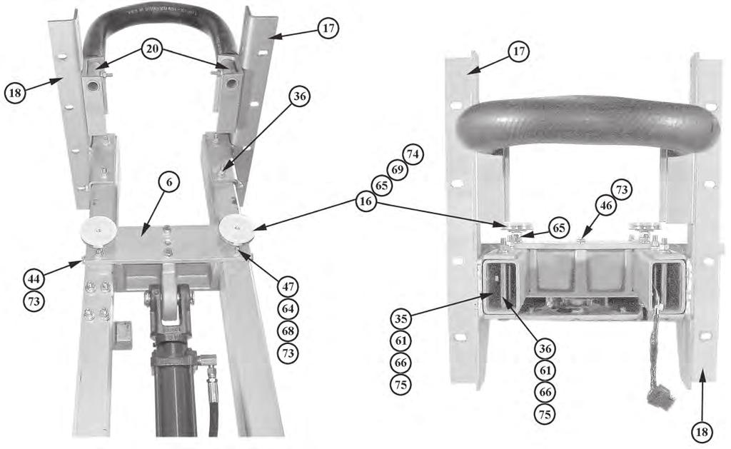
16 VI. TROUBLESHOOTING All units are tested after final assembly to ensure proper operation and adjustment. No further adjustments should be required unless excess movement is noted. A. Excess Movement of the Rack and Ladders If the rack and ladders appear to be moving more than when the System was initially installed, it is probably due to one of the following reasons:. Ladders and rack not properly seated against the vehicle mounted ladder stop. A ladder stop must be provided by the apparatus manufacturer to prevent the ladders from swaying. If the ladder rack is not touching the stop, swaying will occur. Shims may be required to close the gap.. Booms move freely when the rack is pushed or pulled by hand. Use the following procedure for adjusting the hydraulic cylinder (8), bumpers (6) and latch (9). Refer to Figures 7 and 8 on page 7 for numbers in parenthesis. a. Remove ladders with the rack in the down position. Raise the unit back up approximately 3/ of the way and loosen the two bumper lock nuts (65). Turn the bumpers (6) towards the backing plate (6). b. Raise the rack up until the cylinder is fully extended and the latch (9) closes. The hydraulic pump will slow down when the cylinder is fully extended. c. Pull booms ( and 3) out by hand to apply load on the cylinder (8). d. Check the gap between the inside face of the latch (9) and the outside face of the latch bar (0). The gap should be around 3/3" when pulling out on the boom assembly by hand to take the free play out of the unit. If the gap is less than 3/3", the overall length of the cylinder has to be lengthened. If the gap is more than 3/3", the overall length of the cylinder has to be made shorter. e. The length of the cylinder may be adjusted as follows:. Loosen the 3/8" socket head cap screw clamp bolt on the shaft clevis pin.. Lower the rack so the latch (9) opens and the latch bar (0) just clears the latch. This takes the pressure off the cylinder which will make the next step easier. -6-
17 A. Excess Movement of the Rack and Ladders (continued) 3. Turn the cylinder shaft in the appropriate direction to lengthen or shorten it. WARNING: Do not use a pipe wrench or vise grips. Damage to the cylinder shaft will occur. The shaft will almost always turn by hand. Rubber coated work gloves will increase your grip. f. After turning the shaft about / turn, raise the unit back up. Do not tighten the clevis clamp bolt at this time. g. Make sure the cylinder is fully extended and re-check for the 3/3" gap while pulling out on the boom assemblies. FIGURE 7 FRONT VIEW FIGURE 8 SIDE VIEW h. After the 3/3" gap is achieved, tighten the clevis clamp bolt and turn the bumpers until they are touching the base casting (). Maintain outward pressure on the boom while you are hand tightening the bumper. i. Lower the unit a few inches. Turn the bumpers out one full turn away from the backing plate. Re-tighten the bumper lock nuts (65). j. Raise the unit back up to full cylinder extension. Listen for the pump to slow down. The gap between the inside face of the latch (9) and the outside face of the latch bar (0) should now be /6" to 3/6" and the unit will be tight. -7-
18 B. Rack Moving in a Jerking Motion or Stops. Check fluid level in the hydraulic pump.. Follow filling procedure (VII. C..). VII. MAINTENANCE A. Periodic. Any time the ladder rack and ladders appear to sway, refer to Troubleshooting (VI. A.) and follow suggestions depending upon your specific problem.. Visually inspect hydraulic system for leaks indicated by the presence of hydraulic fluid or the accumulation of dirt around a fitting. Refer to Checking Hydraulic Fluid Level (VII. B..) before proceeding. 3. Visually inspect the plastic pads for wear. Pads are located at several points on the ladder rack assembly and are designed to minimize wear to the ladders. Replace as required. B. Semi-Annually or at Scheduled Apparatus Lube Service The above items under Periodic Maintenance should be checked first and then proceed as follows:. Lubricate the following parts as indicated. a. Joints and pivot points should be sprayed with CRC brand Stor&Lub long term lubricant and rust preventative #0303. Excess lubrication should be wiped off. b. Hydraulic ram is self-lubricating and should require no additional lubrication. c. Grease fittings are located on the bottom of the lower shaft (), one on each side under the booms, and there is one additional grease fitting in the lower cylinder pin (57). Use chassis lube at these three points. d. Latch bar (0) and latch (9) should be lubricated with door jam grease where the two parts come together. -8-
19 FIGURE 9 HYDRAULIC SYSTEM COMPONENTS B. Semi-Annually or at Scheduled Apparatus Lube Service (continued). Checking hydraulic fluid level. Hydraulic system is a closed loop system. No one, other than a qualified hydraulic pump technician, should attempt to remove any fittings or hoses from the system. The system contains one orifice which is restricted to.05" (30). Removal of this fitting could cause bodily injury. See location on Figure. a. The booms must be lowered completely to view oil level in reservoir. b. Remove Elbow (8) and Breather Filter from front of reservoir. -9-
20 B. Semi-Annually or at Scheduled Apparatus Lube Service (continued) c. View oil level through Breather/Fill Port. Oil should be 3/8" to /" below the bottom of the Port. d. If oil needs to be added, Zico recommends: SAE 5W0, or other clean hydraulic oil with a viscosity of 50 to 300 SUS at 00 degrees Fahrenheit. System capacity (dry) is 50 ounces. C. Replacing Hydraulic Fluid in the System The whole procedure may take one to two hours. Have replacement reservoir seal and 50 ounces of fluid available before starting the job. Hydraulic fluid in this sytem may be under pressure. Always wear safety glasses and protective clothing and use the following procedure to change the fluid:. Lower the booms and remove the ladder rack and ladders.. Slowly remove the hydraulic lines from the fittings on the front side of the pump. See Figure. 3. Disconnect the electric wires to the hydraulic pump.. Remove the two bolts (5) and lock washers (73) holding the power unit mounting bar (3) to the base casting () and remove the power unit (7). 5. Clamp the mounting bar (3) in a vise with the pump held in the vertical position (same as mounted position). 6. With the pump mounted in the vise, remove the Breather Elbow (8) and Breather. Release the pump from the vise and drain oil into a pan via the Breather/Fill Hole. Loosen and remove the two screws holding the reservoir to the pump. Clean reservoir. 7. Check the two filter screens in the bottom of the pump and clean if necessary. 8. Place the two open hydraulic lines into a receptacle. Raise and lower the booms by hand to blow the fluid from the hydraulic cylinder (8). CAUTION: Control the raising and lowering of the booms. Do not allow them to drop uncontrolled. -0-
21 C. Replacing Hydraulic Fluid in the System (continued) 9. Replace reservoir onto the bottom of the pump using new seal. Replace and tighten screws holding reservoir to pump. 0. Re-attach the pump onto the base casting and re-attach the hydraulic lines and electric power.. Put 3 ounces of fresh hydraulic fluid into the pump through the Breather/Fill Hole.. Run the booms up and down three or four times. Bleed air from the lines the first time. Wait approximately 5 minutes and, with the booms down, check the fluid level. Approximately 8 ounces of fluid will have been replaced into the lines and hydraulic cylinder. 3. Add ounces of fluid to the reservoir, cycle system a few more times, and then recheck oil level. /8" to /" below port is good.. A couple of more ounces of fluid may have to be added to bring the fluid up. When the full level is obtained, reinstall Breather Elbow and Breather. Oil change complete. D. Replacing the Hydraulic Cylinder Elbow adapter fittings (30 & 3) are provided on replacement hydraulic cylinders. The elbow adapter with restricted orifice (30) should not be removed from the cylinder for any reason. Wearing safety glasses and protective clothing, you may use the following procedure to change the hydraulic cylinder:. Make sure the latch (9) is securely in place. As a precaution, secure the booms to the apparatus so they cannot come down on their own.. Remove the fluid lines (see Figure 9, page 9) from the elbow adapter fittings. Do not remove the elbow fittings from the cylinder. Place the open ends of the fluid lines into a receptacle to catch the fluid. 3. Loosen the socket head cap screw on the lower side of the top clevis clamp. Note cylinder to clevis relationship.. Remove pin (57) from the lower clevis clamp. 5. Turn the cylinder counterclockwise to remove the cylinder ram from the top clevis clamp yoke. 6. Replace the cylinder and turn clockwise to re-attach the cylinder ram into the top clevis clamp yoke. 7. Replace pin (57) through the lower clevis clamp. 8. Re-tighten the socket head cap screw on the lower side of the top clevis clamp; reattach the hydraulic lines, and remove the device used to secure the booms to the vehicle in step. --
22 D. Replacing the Hydraulic Cylinder (continued) 9. CAUTION: The following instructions will leave boom rack uncontrolled. Manual control of boom will be necessary via fork lift or overhead crane. When ready, unlatch latch and lower boom all the way. 0. Remove Breather Elbow (8) and Breather. Add oil to reservoir up to bottom of port.. Slightly loosen the fitting on the bottom of the cylinder. Run the pump up to blow air out of the Up line. Retighten, and with the pump raise boom all the way up. Additional oil may be needed to achieve this.. Slightly loosen the fitting at ram end of cylinder and run the pump to bleed air from the line. Retighten and run the system Down all the way. 3. Add oil to the reservoir until it is /" to 3/8" below the Fill Port. Run system a few more times, allowing air to settle out. Check oil level. When level is acceptable reinstall the Breather Elbow and Breather.. Check the gap between the latch (9) and latch bar (0). If the gap is /6" to 3/6", you are done. If the gap is greater than this range, you will need to follow the steps under VI. A.. (page 6) to re-adjust the length of the cylinder ram. E. Replacing Latch Limit Switch The following procedure may be used to replace the latch limit switch:. Lower the booms to gain access to the limit switch ().. Remove the old switch. Match the new switch to the old and set the roller follower arm on the same angle. 3. Mount the new switch.. With the booms up and the latch actuator retracted, lift up on the front of the latch (9) and listen for the latch limit switch to click. It should click when the bottom front side of the latch is approximately / to 3/8" above the top surface of the latch bar casting. 5. To adjust the roller follower arm, loosen the Allen cap screw that locks this arm in place. Move this arm until the switch clicks with the / to 3/8" clearance. F. Pressure Washing Do not operate pressure washer around or near the hydraulic pump. Excessive pressure may allow soap and water to blow past the seal, damaging the hydraulic cylinder. VIII. SERVICE If you experience any problems with your Horizontal Access System, please call us at for assistance. Please have the serial number of your system available. This number may be found on metal plate riveted to the base casting. --
23 IX. WARRANTY A copy of the warranty registration MUST be returned to ZICO to ensure registration of your System (see back cover). X. DRAWINGS, DIAGRAMS AND CHARTS A. Basic System. Complete parts photos for HLAS/HPTS (Figure, page 7 through Figure, page 30). Chart of HLAS component parts (Chart, page 6) 3. Complete parts listing and drawing for HPTS (Figure 0, pages and 5). Space requirement for system (Figure, page 3) 5. Changing length of booms (Figure, page 3) 6. Ladder stop (Figure 3, page ) 7. Handle assembly (Figure, page ) 8. Ladder guard kit (Figure 5, page 5) 9. Rung wear sleeve (Figure 6, page 5) 0. Adjustment procedure to arrest excessive movement (Figures 7 & 8, page 7) B. Electrical System. Electrical control panel with mounting dimensions (Figure, page 3). Ladder/Tank control panel with mounting dimensions (Figure 3, page ) 3. Electrical diagrams (Figure 6, page 6 and Figure 7, page 7). Flashing light kit (Figure 0, page 0 and Figure, page ) 5. Latch limit switch (see VII. E., page, Figure, page 8) C. Hydraulic System. Pump and hydraulic system (Figure 9, page 9). Restricted orifice fitting (Figure 9, page 9) -3-
24 ITEM NO. PART NO. DESCRIPTION QTY Rack Weldment Safety Stop Bracket Quick Release Strap Belt Adjustable Side Guard Screw, 3/8-6 x 3/ HH, C/S GR Nut, 3/8-6 Nylon Lock Hex SS Flatwasher, 3/8 SS Screw, /-0 x 7/8 HH, C/S GR Nut, /-0 Nylon Lock, Hex SS Flatwasher, / SS Upright Wear Sleeves Screw, 5/6-8 x 3 /, HH GR Flatwasher, 5/6 Nom Lockwasher, 5/6 Nom Hex Nut, 5/6-8 8 FIGURE 0 COMPONENTS FOR MODEL HPTS PORTABLE TANK SYSTEM --
25 -5-
26 ITEM PART NO. DESCRIPTION QTY * NOT PROVIDED Base Casting Boom-Left Hand Boom-Right Hand Lower Shaft, Boom Upper Mtg. Block Casting, Cyl. Backing Plate, Upper Mtg. Blk. Power Unit, Hydraulic Hyd. Cyl..5" x 8" Stroke Latch Latch Bar Actuator, Latch ø x " Stroke Limit Switch, Latch Latch Spring Housing-Upper Latch Spring Housing-Lower Latch Spring Bumper, Mech. Stop Boom Ext Weldment-Left Boom Ext Weldment-Right Ladder Rack Weldment Safety Loop, 5" O.A.L. Safety Loop, 3" O.A.L. Sleeve, Safety Loop-8-/" Lg. Bracket, Safety Loop Adjustable Ladder Side Guard Upright Wear Sleeves-8-3/" Elbow, PU to Hose (7/6-0) Hyd Flex Hose-Short - 0 3/"L Hyd Flex Hose-Long - 9"L / OD Hyd Line Assy. 0 Hydraulic Fluid, Qt. NS Elbow/Adapter w/orifice Elbow/Adapter Mtg. Bar, Power Unit Spin Drive Grease Fitting-/-8 Spin Drive Grease Fitting-/-8 5 Screw, 7/6ø x -/ HH SZP Gr 8 Screw, 7/6ø x HH SZP Grade 8 Base Mounting Screws NS Screw, #6-3 x 5/8 Pan Hd SZP Screw, #6-3 x -/8 Pan Hd SZP Screw, /-0 x -/" Hex Hd Screw, 5/6-8 x 3-/" Hx Hd SZP Grade 8 Screw, 5/6-8 x -3/" Flat Hd SZP Grade 8 Screw, 3/8-6 x 3 FH-Phil SZP Screw, 3/8-6 x -3/" Hex Hd SZP Grade 8 Screw, 3/8-6 x 3/" Hex Hd SZP Screw, 3/8-6 x Hex Hd SZP Screw, 3/8-6 x -/" Hex Hd SZP Grade 8 Plastic Elbow Screw, 5/6-8 x 3 Hex Hd SZP Setscrew 5/6-8 x /" Cup Pt. Plated Boot, Red Clevis Pin, /ø x Lg. SZP Clevis Pin, /ø x -/ Lg. SZP Clevis Pin, /ø x -3/ Lg. SZP Clevis Pin, /ø x -/ Lg. SZP Cylinder Pin, "ø (Upper) 8 8 ITEM PART NO. DESCRIPTION QTY Cylinder Pin, "ø (Lower) Cotter Pin, /6 x / Cotter Pin, /8 x 3/ Cotter Pin 5/3 x -/ Flatwasher, 7/6 ID SZP Lock Nut, /-0 SZP Hex Nut, 5/6-8 SZP Hex Nut, 3/8-6 SZP Hex Nut, /-3 SZP Hex Nut, 7/6- SZP Flatwasher, 5/6 ID SZP Flatwasher, 3/8 ID SZP Flatwasher, / ID SZP Lockwasher, #6 SZP Plug, Shipping Lockwasher, 5/6 ID SZP Lockwasher, 3/8 ID SZP Lockwasher, / ID SZP NS Lockwasher, 7/6 ID SZP (8) Helical Bundling Wrap-" (9) Latch Act. Wire Harness-7.5' Elec. Panel Assembly Switch Panel Assembly Handle, Ladder Retainer Retainer Housing - Medium - 8.5" L Retainer Housing - Full "L Compression Spring Socket Hd Screw, /-3 x 7 Screw, 5/6-8 x / Socket Hd, GR 8 Wear Pads Clearance Light Plate, Limit Switch Limit Switch Harness, Limit Switch (included w/89) Screw, #-0 x / Self Tap Rnd Hd Screw, #6-3 x 5/6 Self Tap Rnd Hd Cable Tie, 6" In Line Splice 6- Jacketed Cond Cable Snap Plug Connector Straight Conn., Plastic, / NPT 6 Ga Lead Wire - Black 6 Ga Lead Wire - White Nut, Self Locking 5/6-8 Ladder Rack Rubber Bumper Screw, 5/6-8 x / Hex Hd GR 8 Paint, Touch Up, Oz. Can Label, "danger, loss of hyd. fluid" Label, "warning, pinching of fingers" Label, "warning, striking injury" Cap, Plastic - 3/ø Nom. Setscrew, 7/8- Hollow Lock Ret. Ring, ø Ext. Wear Strip Support, Retainer Handle Screw, 5/6-8 x Socket Head Boom End Cap, Plastic Nylon Washer, / ID x 3/ OD x.06 Label, "to prevent wear" Tag, "Caution Remove Plug" NS NS (6) (6) NS NS NS NS (3) 6' 7' 7' 0 NS - Not Shown on Figures to *Indicates New Item ( ) - See Figure Labels Not Shown CHART HLAS PARTS LISTING -6-


27 FIGURE HYDRAULIC COMPONENTS -7-


28 MODEL HLAS COMPONENT PARTS - HORIZONTAL LADDER ACCESS SYSTEM FIGURE HYDRAULIC AND ELECTRICAL LATCH COMPONENTS -8-


29 FIGURE 3 BOOM COMPONENTS -9-


30 Optional Stop (sold separately) FIGURE END OF BOOM AND RACK COMPONENTS -30-
31 Ziamatic Corp. TOLL FREE: West College Avenue, P.O. Box 337, Yardley, PA (5) FAX: (5) 93-0 *ZICO is a registered trademark for fire, safety and marine products made by Ziamatic Corp. Copyright Ziamatic Corp
32 WARRANTY REGISTRATION Please mail or fax a copy to ZICO to register your unit fire department name: contact person: phone no.: fax no.: street address: p.o. box: city: state zip: model no.: (check one) HLAS-975 HLAS-00 HPTS serial no. on unit: (see page 5 for location) installed on: (vehicle mfg.) delivered: (date) WAS unit installed on: new vehicle retrofitted onto existing vehicle ladders mounted on the unit: duo safety ft. extension, model alco lite ft. extension, model duo safety ft. roof, model alco lite ft. roof, model duo safety ft., model alco lite ft., model other (mfg.) ft. extension, model ft. roof, model ft., model where did you hear about our product? magazine ad (specify) dealer (specify) vehicle mfg. (specify) another department (specify) other (specify) -3-
SAE 5W20, or other clean hydraulic fluid with a viscosity of 150 to 300 SUS at 100 degrees Fahrenheit. System capacity (dry) is 50 ounces.
 is 50 ounces.") QUIC-LIFT Horizontal Ladder & Portable Tank Systems Model HLAS-500-KIT Hydraulic Power Unit (Pump & Motor) and Hydraulic Cylinder Upgrade Kit ZICO 3097PM22 REV. 11-9-16 Note: This manual should be used
QUIC-LIFT Horizontal Ladder & Portable Tank Systems Model HLAS-500-KIT Hydraulic Power Unit (Pump & Motor) and Hydraulic Cylinder Upgrade Kit ZICO 3097PM22 REV. 11-9-16 Note: This manual should be used
ZICO 3094PM1. Model VS REV Retracted. Extended
 QUIC-STEP Retractable Vehicle Step Model VS-- Parts and Instruction Manual ZICO 309PM REV. -- Retracted Extended Designed specifically for use on fire and emergency vehicles. May be retrofitted onto existing
MODEL DESCRIPTION IN LBS.
 QUIC-STEP Retractable Vehicle Step Model VS--9 Parts and Instruction Manual ZICO 309PMii Rev. -- Designed specifically for use on fire and emergency vehicles. May be retrofitted onto existing apparatus.
ZICO 3092PM1 REV Booklet contains the following sections:
 QUIC-LIFT Outside Arm Ladder System Model OALS Parts and Instruction Manual ZICO 309PM1 REV. 7-1-13 Booklet contains the following sections: I. Systems Available II. Operating the System III. Standard
ZICO* 3096PM1 QUIC-LADDER SWING OUT & DOWN VEHICLE LADDER. Stores ladder parallel to the body.
 QUIC-LADDER SWING OUT & DOWN VEHICLE LADDER ZICO* 309PM REV. --0 Stores ladder parallel to the body. Release the locking handle and pull the ladder out to a comfortable climbing angle. The ladder automatically
MODEL DESCRIPTION IN LBS.
 QUIC-RELEASE Oxygen Tank System Model QR-OTS- -U Parts and Mounting Information ZICO 00PM0 Rev. --7 Model QR-OTS-U allows you to mount any "M" through "J" cylinder. The system uses a QR-MV Multiversal
Note: Model numbers carried suffix -03 until January 1, 1997, when it was dropped.
 QUIC-LIFT Ladder Access System Model LAS ZICO 397PM Parts and Instruction Manual REV. --5 I. SYSTEMS AVAILABLE Refer to combination chart (page 8) for the correct combination number for the ladders you
Model numbers carried suffix -03 until January 1, 1997, when it was dropped.
 Fire, Safety, and Marine Equipment 0 West College Ave., Yardley, PA, 906-33 (5) 93-36 -00--FIRE FAX (5) 93-0 www.ziamatic.com e-mail: zservice@ziamatic.com QUIC-LIFT SYSTEMS I. SYSTEMS AVAILABLE Refer
ZICO 3097PM19 REV I. SYSTEMS AVAILABLE
 QUICLIFT Ladder Access SystemHydraulic Model LASHA Parts and Instruction Manual ZICO 3097PM9 REV. 78 I. SYSTEMS AVAILABLE Refer to combination chart (page 4) for the correct combination number for the
Hard Sleeve System complete with two 10' aluminum trays
 QUICLIFT Ladder Access SystemExtend Down Model LASXT Parts and Instruction Manual ZICO 3097PM Rev. 36 I. SYSTEMS AVAILABLE Refer to combination chart (page 4) for the correct combination number for the
DESCRIPTION. 10" Square Valve 10" Valve for United Plastics Tank Valve Handle-Complete Assembly Auxilliary Handle Lock less Hardware (see page 12)
") QUIC-FLOW MANUAL DUMP VALVE ZICO 070PM REV 3-5- QUIC-FLOW valves are the fastest dumping systems for tankers, bar none, dumping up to 800 GPM. Mounting the valve at the bottom of the tank provides approximately
QUIC-FLOW MANUAL DUMP VALVE ZICO 070PM REV 3-5- QUIC-FLOW valves are the fastest dumping systems for tankers, bar none, dumping up to 800 GPM. Mounting the valve at the bottom of the tank provides approximately
ZICO 2070PM1 REV Page 1
 QUIC-FLOW Dump Valves Parts and Instruction Manual ZICO 070PM REV. 9-0- Zico dump valves are uniquely designed to stop annoying leakage. A special slotted hinge over the door shifts when in the closed
3094PM1ii (Model VS-24-11) & 3094PM4ii (Model VS-24-9)
 & 3094PM4ii (Model VS-24-9)") QUIC-STEP Retractable Vehicle Step Model VS-24-11 and VS-24-9 InPOWER Control Module Upgrade Manual ZICO 3094PM9 REV. 1-13-17 Note: This manual provides instruction when upgrading a vehicle step from a
QUIC-STEP Retractable Vehicle Step Model VS-24-11 and VS-24-9 InPOWER Control Module Upgrade Manual ZICO 3094PM9 REV. 1-13-17 Note: This manual provides instruction when upgrading a vehicle step from a
69-74 VW Beetle IRS Rear Kit Part No
 www.airliftcompany.com 69-74 VW Beetle IRS Rear Kit Part No. 75615 MN-476 (01102) ECN 3455 Please read these instructions completely before proceeding with installation A C B E D AA F F ITEM QTY. PART
ZICO. Center Pull Release in Bostrom 450 Tanker Seat 1026PM5 REV
 Center Pull Release in Bostrom 450 Tanker Seat Manual For the EZ-LOC Mechanical Bracket ZICO 1026PM5 REV. 2-24-12 The center pull release kit allows the SCBA bracket to be released by pulling a "T" handle
It don t mean a thing If it ain t got the swing
 SWING CHUTE SAND/SALT SPREADER INSTALLATION AND OPERATING INSTRUCTIONS SWING CHUTE SPREADER MODELS: 7, 8, 9, 9.5 & 10 MANUAL FOR SPREADER SERIAL NUMBERS AFTER # 20000 It don t mean a thing If it ain t
RHINO SUSPENSION SYSTEM INSTALLATION INSTRUCTIONS
 PARTS INCLUDED: 2 FRONT UPPER A-ARMS 2 FRONT LOWER A-ARMS 2 UNI-BALL JOINTS 2 UNI-BALL JOINT STUDS 2 UNI-BALL JOINT CAPS 2 RETAINING RINGS 1 FRONT SHOCK ASSEM. 2 DELRON STEERING STOPS 2 SHOCK MOUNT SPACERS
AL625 & AL625HD INSTALLATION & OWNER S MANUAL
 AL625 & AL625HD INSTALLATION & OWNER S MANUAL These instructions are provided to assist you in the installation of the AL625. If you require further assistance, our trained staff is ready to provide you
400 SERIES HYDRA-LIFT KARRIERS
 OPERATOR S MANUAL FOR HYDRA-LIFT DRUM KARRIERS - Serial # 0802 to (MMYY) The letter A in the model number indicates that the unit is for 55 gallon standard steel drum ( 22½ diameter). Model Dispensing
KIT No , and 80590
 KIT No. 80531, 80545 and 80590 by MN-354 (05603) ECR 5593 Please read these instructions completely before proceeding with installation Air Spring Kit Parts List Item Description Quantity A Air Spring
Tooling Assistance Center
 Safeguards are designed into this application equipment to protect operators and maintenance personnel from most hazards during equipment operation. However, certain safety precautions must be taken by
Dual Remote Filtration System Installation and Servicing Instructions
 IMPORTANT NOTICE Read all instructions completely before attempting to install this unit. Improper installation could result in serious system and/or equipment damage. The installation of this system is
Service Jacks. Operating Instructions & Parts Manual. Model Number. Capacity 4 Ton 4 Ton Air/ Manual 10 Ton 10 Ton Air/ Manual HW93657/ HW93660
 Service Jacks Operating Instructions & Parts Manual Model Number HW93657 HW93667 HW93660 HW93662 Capacity 4 Ton 4 Ton Air/ Manual 10 Ton 10 Ton Air/ Manual Made in North America HW93657/ HW93660 HW93667/
BMK-18 U.S. Patent #5,298,158
 BMK- U.S. Patent #5,29,5 Marine Dual Remote Filtration System Mounting Kit Installation and Servicing Instructions IMPORTANT NOTICE Read all instructions completely before attempting to install this unit.
82-01 Chevy S-10/ GMC Sonoma Front Kit Part No B
 www.airliftcompany.com 82-01 Chevy S-10/ GMC Sonoma Front Kit Part No. 75512B MN-481 (02105) ECN 3549 Please read these instructions completely before proceeding with installation Left Side Upper Shock
Kit No Please read these instructions completely before proceeding with installation. Air Spring Kit Parts List. Bracket Attaching Hardware
 Kit No. 59532 MN-572 (021108) ECR 7136 Please read these instructions completely before proceeding with installation Air Spring Kit Parts List A Item Description Quantity A Air Sleeves 2 B Upper Brackets
WARNING NOTICE CAUTION ASSEMBLY INSTRUCTIONS
 MODEL 284 EZ-GLIDE SYSTEM 10' HIGH CUBE VAN DRIVER SIDE ALUMINUM DROP DOWN LADDER RACK ATTENTION Read and understand all instructions and warnings before operating or using this product. WARNING This product
Please read these instructions completely before proceeding with installation. Read all maintenance guidelines on page 7 before operating the vehicle.
 MN-643 (02511) ECR 5461 Kit No. 39205 Please read these instructions completely before proceeding with installation Item P/N Description Quantity A 26391 Driver-Side Beam Assembly 1 B 26414 Passenger-Side
UNIVERSAL PUMP HANGER INSTALLATION INSTRUCTIONS
 UNIVERSAL PUMP HANGER INSTALLATION INSTRUCTIONS WARNING! THESE INSTRUCTIONS MUST BE READ AND FULLY UNDERSTOOD BEFORE BEGINNING INSTALLATION. FAILURE TO FOLLOW THESE INSTRUCTIONS MAY RESULT IN POOR PERFORMANCE,
INSTALLATION AND PARTS MANUAL MODEL 30B FOR NEW HOLLAND DC75, DC85, DC95X
 CARCO INSTALLATION AND PARTS MANUAL MODEL 30B FOR NEW HOLLAND DC75, DC85, DC95X NOTE: This manual covers mounting and control group installation, and parts specific to this winch on the specified tractor.
Ram 1500 Crew Cab A Ram 2500/3500 Crew Cab A
 I N S T A L L A T I O N G U I D E APPLICATION AMP Part # Ram 1500 Crew Cab 2013-2015 77138-01A Ram 2500/3500 Crew Cab 2013-2015 77138-01A Note:The application works only on the Crew Cab model Vehicles.
GRAIN CART TARP SYSTEM INSTALLATION AND OPERATION MANUAL
 GRAIN CART TARP SYSTEM INSTALLATION AND OPERATION MANUAL Grain Carts KITS Thunderstone Manufacturing, LLC. 3400 West O Street Lincoln, NE 68528 402-435-4249 (Fax) 402-438-3918 www.thunderstonemfg.com Aluminum
UNIVERSAL PUMP HANGER INSTALLATION INSTRUCTIONS
 UNIVERSAL PUMP HANGER INSTALLATION INSTRUCTIONS WARNING! THESE INSTRUCTIONS MUST BE READ AND FULLY UNDERSTOOD BEFORE BEGINNING INSTALLATION. FAILURE TO FOLLOW THESE INSTRUCTIONS MAY RESULT IN POOR PERFORMANCE,
Installation Instructions
 Contents Page General Information and Installer Tips.......... 2 Panels & Posts............................. 3 Enclosure Description..................... 4 Hinge Door Hardware................... 4-5 Step-by-Step
Robo-Assist Accessory
 Robo-Assist Accessory Kit 85607617 For use with BaseLine by COATS Tire Changers This is a supplement to your operating manual and covers the installation and use of the Robo-Assist accessory. If you do
P Original Series Cargo Van Lift Mounting Instructions Fullsize Ford Van present. Preparing the Gate
 Fullsize Ford Van- 1992-present Preparing the Gate 1. Remove the mounting hardware which is banded to the liftgate. 2. Verify mounting kit (Figure 1 and Table 1). S-400-40 STRAP VAN MOUNTING EAR BENT BRACKET
CALIFORNIA TRIMMER MOWER MAINTENANCE MANUAL
 CALIFORNIA TRIMMER MOWER MAINTENANCE MANUAL 2 Table of Contents Section 1: General Information Page Handle Assembly Instructions 4 Maintenance All Models 6 Oil Change Procedures All Models 9 Height Adjustment
MODEL 400A-60 & 400Z-72 HYDRA-LIFT KARRIERS
 OPERATOR S MANUAL FOR 400Z SERIES MANUAL TILT S The letter Z in the model number indicates that the unit is for 55 gallon standard steel drum ( 22.5 diameter) and accepts attachments to handle a 55 gallon
RITE WAY MFG. CO. LTD. P.O.
 CO. LTD. P.O. Box 328 Imperial, Saskatchewan Canada, S0G 2J0 Ph: (306) 963-280 Fax: (306) 963-2660 Web Site: www.ritewaymfg.com E-mail: info@ritewaymfg.com Table of Contents SPECIFICATIONS... WARNING...2
! CAUTION! ! WARNING!
 Assembly Instructions! 3N-3010P, No-Till Flat Fold Marker Option Used with: 3N-3010P Drills When you see this symbol, the subsequent instructions and warnings are serious - follow without exception. Your
Hustler X-ONE i Parts Manual
 Hustler X-ONE i Parts Manual 00 South Ridge Road Hesston, Kansas 6706 Table of Contents General Information Service Literature...................................... - Options Available From Your Dealer........................
ILLUSTRATED PARTS LIST THIS MANUAL CONTAINS THE ILLUSTRATED PARTS LIST FOR MODELS:
 IPL MODEL SWZU 1 6 2 6 6 6 6 ILLUSTRATED PARTS LIST 0 2 6 8 THIS MANUAL CONTAINS THE ILLUSTRATED PARTS LIST FOR MODELS: SWZU6-1KA with a serial number of 260001 to 26 SWZU8-1KA with a serial number of
20" FLOORKEEPER EZ BRUSH DRIVE
 TORNADO INDUSTRIES 7401 W. LAWRENCE AVENUE CHICAGO, IL 60706 (708) 867-5100 FAX (708) 867-6968 www.tornadovac.com Tornado Parts List Manual For Commercial Use Only 20" FLOORKEEPER EZ BRUSH DRIVE MODEL
GPS AutoSteer System Installation Manual
 GPS AutoSteer System Installation Manual Supported Vehicles Case IH Vehicles Case 2577 Combines Case 2588 Combines Accuguide Ready PN: 602-0233-01-A LEGAL DISCLAIMER Note: Read and follow ALL instructions
BigDog Mowers Alpha Parts Manual
 BigDog Mowers Alpha Parts Manual 00 S. Ridge Road Hesston, Kansas 70 Table of Contents General Information Service Literature.................................................. - Options Available From
Hydro-Sync Slide-Out System
 Hydro-Sync Slide-Out System SERVICE MANUAL Rev: 08.14.2018 Hydro-Sync Slide-out System Service Manual TABLE OF CONTENTS Safety Information 3 Product Information 3 Operation 4 Extending Slide-Out Room 4
MK-5000G exploded VieW
 Frame accessories 38 cutting head Pump Assembly 39 connecting linkage foot pedal linkage 40 curtain blade guard 41 ENGINE Assembly 42 PARTS LIST A Frames - - A1 Frame, MK-5000 Main 1 155541 B Pivot Bracket
Post Driver Attachment
 Attachment (Shown with Optional Power Cell Rotator) Models - 600, 850 Safety Instructions This safety alert symbol indicates important safety messages in this manual. When you see this symbol, carefully
EZ Build Assembly and Installation
 Form No. 1-1058 March 2012 EZ Build Assembly and Installation 41500 Lot Pro Diamond Edge Plow with E-72 12V Hydraulic Unit Meyer Products LLC reserves the right, under its continuing product improvement
PRO HYDRO WALK BEHIND MOWERS MID-SIZE SERIES 3
 Parts Manual for MID-SIZE SERIES 3 POWER UNIT MODELS SPLH153KW SPLH173KW MOWER MODELS SPA361 SPA481 SPA521 SPA611 McDonough, GA, 30253 U.S.A. COPYRIGHT 2005 SNAPPER PRODUCTS, INC. ALL RIGHTS RESERVED.
TORNADO ILLUSTRATED PARTS 20" FLOORKEEPER EZ BRUSH DRIVE (SERIES C) CATALOG NO , 99105A & 99105B
 CATALOG NO , 99105A & 99105B") TORNADO INDUSTRIES 7401 W. LAWRENCE AVENUE CHICAGO, IL 60706 (708) 867-5100 FAX (708) 867-6968 www.tornadovac.com TORNADO 20" FLOORKEEPER EZ BRUSH DRIVE (SERIES C) CATALOG NO. 99105, 99105A & 99105B ILLUSTRATED
TORNADO INDUSTRIES 7401 W. LAWRENCE AVENUE CHICAGO, IL 60706 (708) 867-5100 FAX (708) 867-6968 www.tornadovac.com TORNADO 20" FLOORKEEPER EZ BRUSH DRIVE (SERIES C) CATALOG NO. 99105, 99105A & 99105B ILLUSTRATED
8 LIFT ASSEMBLY 8.1 LIFT ASSEMBLY PARTS LIST
 8 LIFT ASSEMBLY 8.1 LIFT ASSEMBLY PARTS LIST 24 8.2 LIFT ASSEMBLY PARTS LIST ITEM QTY. DESCRIPTION PART # 1 24 FLAT WASHER, 1/2 ID SAE 6-0248 2 16 LOCKWASHER, 1/2 ID 6-0059 3 17 HEX NUT, 1/2-13UNC 6-0035
3-CAR CARRIER PARTS MANUAL
 -CAR CARRIER PARTS MANUAL 080 Hykes Road Greencastle, PA Phone () 9- www.jerr-dan.com --00009 Rev - February 0, 009 009 Jerr-Dan Corporation. All Rights Reserved. -Car Carrier Parts Manual - Page --00009
'99-03 CHEVROLET/GMC IFS 4WD 6" SUSPENSION SYSTEM P/N INSTALLATION INSTRUCTIONS
 1/16/04 '99-03 CHEVROLET/GMC IFS 4WD 6" SUSPENSION SYSTEM P/N. 10-41099 INSTALLATION INSTRUCTIONS NOTE: Each Lift Kit and options to Lift Kits are packaged separately. Therefore, installation procedures
General Assembly Contents
 General Assembly Contents 636 General Assembly, AL-11182... 1-2 Extendo Boom Assembly, AL-10772... 1-5 636 Boom Tube Assembly w/extra or Standard Circuit, FL-9418... 1-9 Sway Control, AL-11274... 1-11
ALUMINUM & STEEL CAR CARRIERS
 OWNER'S MANUAL ALUMINUM & STEEL CAR CARRIERS INSTALLATION, OPERATION, MAINTENANCE & PARTS NOTE: MANUAL including SPECIFICATIONS, subject to change without notice All ratings specified are based on structural
TECHNICAL DATA BROCHURE ZTR 308/3II
 Date 8/84 Page 1 of 6 TECHNICAL DATA BROCHURE ZTR 308/3II IMPORTANT - READ OPERATOR'S MANUAL BEFORE OPERATION OR MAKING ADJUSTMENTS. ' Seat Adjustment Loosen bolts on sliding brackets under each side of
\ \ ~, en ~ \ \\ en I- ( \\\ b3~(i 5/27/93. æ Lr PECULIAR HYDRAULICS W LL BELT DRIVE, SLC,
 DODGE V8-38\360 W-W/O AC W/SERPENTINE 99-9 PECULIAR HYDRAULICS BELT DRIVE, SLC, UNDERHOOD VALVE 7505 ~., ( \\\ \ \\ ~,/./ LL a: :: z en ~ en I- W LL æ Lr ~,. \ \ \ "',: e /' ~ '\ '- -- - /' "-.. -- - -..
Installation Instructions
 Preparing your vehicle to install your brake system upgrade 1. Rack the vehicle. 2. If you don t have a rack, then you must take extra safety precautions. 3. Choose a firmly packed and level ground to
MOREHOUSE INSTRUMENT COMPANY, INC. 60,000 LBS CAPACITY AIRCRAFT PART NUMBER SCALE S FORCE CALIBRATION PRESS PART NO.
 INDEX 1. GENERAL SPECIFICATION AND DRAWING 804000-03... 2 2. ASSEMBLY INSTRUCTIONS... 5 3. OPERATING INSTRUCTIONS... 6 4. MAINTENANCE INSTRUCTIONS... 7 5. CERTIFICATE OF CAPACITY LOAD TEST AND OVERLOAD...
Liftgate Terminology
 SL-20 Series SL-20 Series Click the appropriate link below for the major component of the liftgate for which you are trying to find the correct part. If you are unsure of the name of the part in Waltco
THE GLIDER 5th Wheel Attachment
 April 2007 APPLICATION: INSTALLATION INSTRUCTIONS MODEL NO. 70460 70046 THE GLIDER 5th Wheel Attachment For use on short bed pickup applications US Patent No. 6247720 COMPLETE PARTS LIST Part Description
HYDRAULIC SLIDEOUT SYSTEM OPERATION AND SERVICE MANUAL
 HYDRAULIC SLIDEOUT SYSTEM OPERATION AND SERVICE MANUAL TABLE OF CONTENTS SYSTEM...... Warning...... Description..... Prior to Operation... Preventative Maintenance..... OPERATION... Warning... Extending
Kit No Please read these instructions completely before proceeding with installation. Parts List G J I K L H CC FF DD MN-505 (01201) NPR 3733
 NPR 3733") Kit No. 57154 MN-505 (01201) NPR 3733 Please read these instructions completely before proceeding with installation Parts List by www.airliftcompany.com Item P/N Description Quantity A 58407 Air Spring
Kit No. 57154 MN-505 (01201) NPR 3733 Please read these instructions completely before proceeding with installation Parts List by www.airliftcompany.com Item P/N Description Quantity A 58407 Air Spring
Walker Loader Bucket OPERATOR S AND PARTS MANUAL
 Walker Loader Bucket OPERATOR S AND PARTS MANUAL Please Read and Save These Instructions For Safety, Read all Safety and Operation Instructions Prior To Operating Machine P/N 6690 TABLE OF CONTENTS Introduction
EZ Build Assembly and Installation
 Form No. 1-1108 April 2014 EZ Build Assembly and Installation 41125 Drive Pro 5.0-6.8 Plow with E-72 12V Hydraulic Unit and 41175 Drive Pro 6.8-7.6 Plow with E-72 12V Hydraulic Unit Meyer Products LLC
Parts Manual EM and EMTC 2500 lb. and 3300 lb. Capacity Flipaway Liftgates
 www.waltco.com Phone: 800.4.5685 parts@waltco.com Fax: 800.4.5684 Parts Manual EM and EMTC 2500 lb. and 3300 lb. Capacity Flipaway Liftgates This manual identifies parts for Liftgates manufactured: /200
INSTALLATION INSTRUCTIONS
 INSTALLATION INSTRUCTIONS [1] Description: Tow Hitch Wire Harness Kit [2] Application: Nissan Rogue Note: Tow Harness application is limited to specific vehicle option packages that include tow harness
Parts Manual for PRO GEAR EXPRESS MID-SIZE WALK BEHIND MOWERS SERIES 0 & 1 POWER UNIT MODEL SPE1250KW SPE140KW SPE150KH SPE151KW SPEL150KH
 Parts Manual for PRO GEAR EXPRESS MID-SIZE WALK BEHIND MOWERS SERIES 0 & 1 POWER UNIT MODEL SPE10KW SPE0KW SPE10KH SPE11KW SPEL10KH MOWER UNIT MODEL SPE30 SPE480 SPE31 SPE481 IT IS POLICY OF SNAPPER TO
MODEL HD-P10000 PLANETARY WINCH
 OPERATING, SERVICE AND MAINTENANCE MANUAL MODEL HD-P10000 PLANETARY WINCH CAUTION: READ AND UNDERSTAND THIS MANUAL BEFORE INSTALLATION AND OPERATION OF WINCH. SEE WARNINGS! TABLE OF CONTENTS INTRODUCTIONS................................................................1
Z-Gate Universal Shifter
 Installation Instructions Z-Gate Universal Shifter Fits: GM, Ford, Lincoln and Chrysler Transmissions See Application Guide for Specific Applications Part #80681 Rev 06/01/2018 WORK SAFELY! For maximum
GPS AutoSteer System Installation Manual
 GPS AutoSteer System Installation Manual Supported Vehicles New Holland Combines CR 9040 CX 9040 CR 9050 CX 9050 CR 9060 CX 9060 CR 9070 CX 9070 CR 9080 CX 9080 IntelliSteer Ready PN: 602-0231-01-A LEGAL
Illustrated Parts Manual
 Illustrated Parts Manual Models 522D LoPro 524D LoPro S/N 0900 P/N - 948-403 Revised July 6, 2007 INTRODUCTION Table of Contents SECTION INTRODUCTION Table of Contents... - thru -4 Alphabetical Index...
LAWN TRACTORS ELECTRIC CLUTCH HYDRO DRIVE SERIES F
 Parts Manual for LAWN TRACTORS ELECTRIC CLUTCH HYDRO DRIVE SERIES F MODELS LT160H42FBV LT160H42FBV2 LT180H48FBV2 IT IS THE POLICY OF SNAPPER TO IMPROVE ITS PRODUCTS WHENEVER IT IS POSSIBLE AND PRACTICAL
INSTALLATION / OPERATING INSTRUCTIONS Reese Elite Series FIFTH WHEEL SLIDER HITCH
 INSTALLATION / OPERATING INSTRUCTIONS Reese Elite Series FIFTH WHEEL SLIDER HITCH DEALER/INSTALLER: (1) Provide this Manual to end user. (2) Physically demonstrate hitching and unhitching procedures in
Owner s Manual. LTS Hide-A-Way Truck Side Gate
 Owner s Manual LTS Hide-A-Way Truck Side Gate 10900 Kenwood Road Cincinnati, OH 45242 Ph: 513-891-6210 Toll-Free: 866-539-6261 Fax: 513-891-4901 www.leymanlift.com sales@leymanlift.com LML00410-11/6/15
CONTENTS. Product Features and Specifications Installation Requirement Installation Exploded View Operation Instruction...
 1 CONTENTS Product Features and Specifications... 3 Installation Requirement... 5 Installation... 6 Exploded View... 20 Test... 22 Operation Instruction... 25 Maintenance... 26 Trouble Shooting... 27 Parts
Assembly Instructions
 Assembly Instructions Part Number Description Model Approx. Assembly Time 99994-049 Cab Enclosure MULE SX 3-4 Hours WARNING Improper installation of this accessory could result in an accident causing serious
MAINTENANCE INSTRUCTIONS
 MAINTENANCE INSTRUCTIONS LSR90 SERIES RAMPS Link Mfg. Ltd. 223 15th St. N.E. Sioux Center, IA USA 51250-2120 The LSR 90 fits Mercedes Benz Sprinters, Ford Transits mid and high roof, Nissan NV high roof,
MIDRISE MODEL SM60F_1 // SM60F_A 6,500 LB. CAPACITY
 INSTALLATION and OPERATION MANUAL READ THIS INSTRUCTION MANUAL THOROUGHLY BEFORE INSTALLING, OPERATING, SERVICING OR MAINTAINING THE LIFT. SAVE THIS MANUAL. NOV 2007 REV.B MIDRISE MODEL SM60F_1 // SM60F_A
INSTALLATION MANUAL. Thunderstone Manufacturing LLC 3400 West O Street Lincoln, NE (Fax)
") INSTALLATION MANUAL August 7 th 2018 43 /48 /50 2011 and Older Timpte STD/Split 36 Style Hopper Trailers with Roller Bearing Doors Kit #101533 for 96w & Kit #101534 for 102w Thunderstone Manufacturing
INSTALLATION MANUAL August 7 th 2018 43 /48 /50 2011 and Older Timpte STD/Split 36 Style Hopper Trailers with Roller Bearing Doors Kit #101533 for 96w & Kit #101534 for 102w Thunderstone Manufacturing
Champion Series Zero-Turn Riders & Mower Decks
 Parts Manual Champion Series Zero-Turn Riders & Mower Decks HP Tractors Mfg. No. Description Champion, HP Zero-Turn Rider Champion, HP Zero-Turn Rider (CE) 0HP Tractors Mfg. No. Description Champion, 0HP
PARTS LIST WRANGLER 2625 DB
 PARTS LIST WRANGLER 2625 DB 1 NOTES 2 BRUSH GEAR MOTOR ITEM PART NO. PART DESCRIPTION QTY. 2393501 COMPLETE MOTOR ASSEMBLY 1 101 3391221 NEGATIVE LEAD 1 102 3391201 1/4-20 X 7 3/4THRU BOLT 2 103 10-24
Slump Master III Slump Inspection and Safety Platform for Single & Double Units
 VERSION: SM88 G3.20 Inspection and Safety Platform for Single & Double Units Operating and Service Manual *Includes Parts List 2014 C & W Manufacturing and Sales Co. Dear Customer, C & W Manufacturing
LC I LIPPERT COMPONENTS HYDRAULIC FULL WALL SLIDEOUT SYSTEM OPERATION AND SERVICE MANUAL
 LC I LIPPERT COMPONENTS HYDRAULIC FULL WALL SLIDEOUT SYSTEM OPERATION AND SERVICE MANUAL TABLE OF CONTENTS SYSTEM...... 3 Warning...... 3 Description..... 3 Prior to Operation... 4 4 OPERATION... Main
! CAUTION! ! WARNING!
 Assembly Instructions! 24- and 30-Foot, No-Till Flat Fold Marker Option Used with: 2N-2410 and 2N-3010 Drills 2N-2420 and 2N-3020 Drills When you see this symbol, the subsequent instructions and warnings
INSTALLATION INSTRUCTIONS
 TM WEIGHTLIFTER Tailgates By THIEMAN TWL 125, 16, 20 INSTALLATION INSTRUCTIONS! IMPORTANT! KEEP IN VEHICLE! PLEASE READ AND UNDERSTAND THE CONTENTS OF THIS MANUAL BEFORE OPERATING THE EQUIPMENT. NTEA T
CHEVROLET TAHOE/DENALI/AVALANCHE/YUKON/ SILVERADO/SIERRA 2007+
 CHEVROLET TAHOE/DENALI/AVALANCHE/YUKON/ SILVERADO/SIERRA 2007+ INSTALLATION INTRODUCTION 1. REMOVING THE FENDER AND DOORS FROM THE A-PILLAR AND DISCONNECTING THE WIRE HARNESS @ THE DOOR JAM 2. REMOVING
WSL-Series. WSL- Series
 WSL-Series WSL- Series Click the appropriate link below for the major component of the liftgate for which you are trying to find the correct part. If you are unsure of the name of the part in Waltco terminology,
Hydro Cut Series Walk-Behind Mowers
 Parts Manual HP Product Mfg. No. Description 92 Hydro Cut, HP Kawasaki, 2 inch (CE) Hydro Cut Series Walk-Behind Mowers Rev. 0/200 Table Of Contents PRODUCT COMPONENTS PAGES Engine Deck & Handle Bars
Hustler Raptor CE Parts Manual
 Hustler Raptor CE Parts Manual 00 South Ridge Road Hesston, Kansas 70 Table of Contents General Information Service Literature.................................................. - Options Available From
Doing Our Best to Provide You the Best. Instructions for 1997 & 1998 Models start on page 5. Jeep Cherokee. 8/16 TP20010,Rev.10
 Jeep Cherokee Jeep Wagoneer Jeep Wagoneer LTD Jeep Comanche Pick-up 8/16 TP20010,Rev.10 Centers-24 Pin Height-16 11 8 9 12 13 14 17 3 6 10 1 2 Use for 1997 & 1998 Jeep Cherokee 5 4 16 7 21 9 1 Use in this
RC-200EX / RC-150EX Rim Clamp Tire Changer
 RC-200EX / RC-150EX Rim Clamp Tire Changer For servicing motorcycle and ATV tire/wheel assemblies as well as automotive and most light truck tire/wheel assemblies (holds 6 to 8-inch wheels for manual tire
Air / Hydraulic Floor Service Jack
 SPX Corporation 655 Eisenhower Drive Owatonna, MN 55060-0995 USA Phone: (507) 455-7000 Tech. Serv.: (800) 533-6127 Fax: (800) 955-8329 Order Entry: (800) 533-6127 Fax: (800) 283-8665 International Sales:
Installation Notes: #86000-R Race Series +3.5 L/T Kit
 159 North Maple St. Unit J, CORONA CA 92880 P. 951-737-9682 F. 951-737-9006 WWW.CHAOSFAB.COM Installation Notes: #86000-R Race Series +3.5 L/T Kit Factory manual is recommended for removal and re-installation
CONTENTS: Ton Hydraulic Shop Press w/ Winch Ton Hydraulic Shop Press w/ Winch OWNER'S MANUAL
 OWNER'S MANUAL CONTENTS: Page 1 Specifications 2 Safety Information and Warranty Information 3 Parts List 4-8 Assembly Instructions 9 Procedure for Bleeding Air 10 Pump Instructions 11-12 Winch Kit List
INSTALLATION INSTRUCTIONS
 INSTALLATION INSTRUCTIONS PARTS LIST Accessory Application Publications No. TRX420 (All) MII 13032 WINCH KIT P/N 08L94-HP5-100 Accessory Weight 35 lbs (16 kg) Honda Dealer: Please give a copy of these
LIFT N LOAD INSTALLATION, MAINTENANCE, & SAFETY INSTRUCTIONS (800)
") LIFT N LOAD INSTALLATION, MAINTENANCE, & SAFETY INSTRUCTIONS (800) 272-6276 001-321-757-7611 www.cramarotarps.com Plants In: Delaware, Florida, Massachusetts, Nevada, Ohio, and Canada General Information
LIFT N LOAD INSTALLATION, MAINTENANCE, & SAFETY INSTRUCTIONS (800) 272-6276 001-321-757-7611 www.cramarotarps.com Plants In: Delaware, Florida, Massachusetts, Nevada, Ohio, and Canada General Information
650 Series Cargo Van Lift Mounting Instructions Fullsize Ford 1992-Present
 TOMMY GATE OWNER'S / OPERATOR'S MANUAL 650 Series 650 LB Capacity 650 Series Cargo Van Lift Mounting Instructions Fullsize Ford 1992-Present Installing the Base Plate 1. Examine the interior and exterior
GPS AutoSteer System Installation Manual
 GPS AutoSteer System Installation Manual Supported Vehicles Agco Gleaner Combines R65 R66 R75 R76 PN: 602-0288-01-A LEGAL DISCLAIMER Note: Read and follow ALL instructions in this manual carefully before