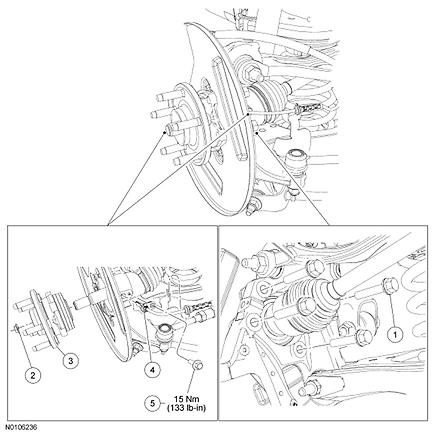
REAR SUSPENSION. Wheel Bearing and Wheel Hub. NOTE: All-Wheel Drive (AWD) shown, Front Wheel Drive (FWD) vehicles similar.
|
|
|
- Stanley Hamilton
- 5 years ago
- Views:
Transcription
1 2009 Lincoln MKS AWD V6-3.7L Vehicle > Steering and Suspension > Wheels and Tires > Wheel Hub > Service and Repair > Removal and Replacement REAR SUSPENSION Wheel Bearing and Wheel Hub NOTE: All-Wheel Drive (AWD) shown, Front Wheel Drive (FWD) vehicles similar. 1/5
2 2/5

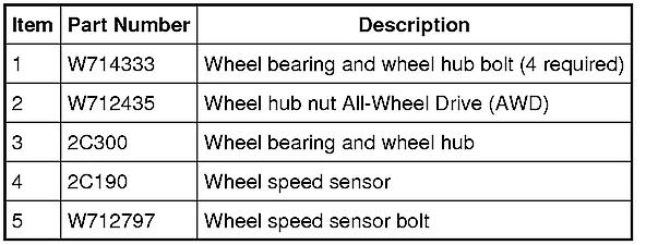
3 Removal NOTICE: Suspension fasteners are critical parts because they affect performance of vital components and systems and their failure may result in major service expense. New parts must be installed with the same part numbers or equivalent part, if replacement is necessary. Do not use a replacement part of lesser quality or substitute design. Torque values must be used as specified during reassembly to make sure of correct retention of these parts. 1. Remove the brake disc. 2. Remove the wheel speed sensor bolt and position the sensor aside. All-Wheel Drive (AWD) vehicles 3. NOTE: Do not discard the nut at this time. Remove the wheel hub nut. 4. Using the Front Wheel Hub Remover, separate the halfshaft from the wheel hub. 3/5
4 5. Remove the 4 bolts and the wheel bearing and wheel hub. - Discard the bolts. 6. NOTICE: The wheel knuckle bore must be clean enough to allow the wheel bearing and wheel hub to seat completely by hand. Do not press or draw the wheel hub and bearing into place or damage to the bearing may occur. NOTICE: Make sure the wheel hub-to-knuckle mating surfaces are clean and free of any adhesive. Failure to clean adhesive from both surfaces may cause bearing damage. Using a clean shop towel, clean the wheel knuckle-to-mating surfaces and inspect the knuckle bearing bore. - If the wheel knuckle is cracked, install a new wheel knuckle. Installation 1. Install the wheel bearing and wheel hub assembly. 2. Install the 4 new wheel bearing and wheel hub bolts. - Tighten the bolts to 133 Nm (98 lb-ft) in a cross-pattern. 3. Install the brake disc. 4. Position the wheel speed sensor and install the bolt. - Tighten to 15 Nm (133 lb-in). AWD vehicles 5. NOTICE: Do not tighten the rear wheel hub nut with the vehicle on the ground. The nut must be tightened to specification before the vehicle is lowered to the ground. Wheel bearing damage will occur if the wheel bearing is loaded with the weight of the vehicle applied. NOTE: Apply the brake to keep the halfshaft from rotating. 4/5
5 Position the halfshaft in the hub and use the previously removed wheel hub nut to seat the halfshaft. - Tighten the nut to 350 Nm (258 lb-ft). - Remove and discard the nut. 6. NOTICE: Install and tighten the new wheel hub nut to specification within 5 minutes of starting it on the threads. Always install a new wheel hub nut after loosening or when not tightening within the specified time or damage to the components may occur. Install a new wheel hub nut. - Tighten the nut to 350 Nm (258 lb-ft). 5/5
Wheel Bearing and Wheel Hub All-Wheel Drive (AWD) Vehicles
 Vehicles") Rear Suspension Wheel Bearing and Wheel Hub All-Wheel Drive (AWD) Vehicles All-Wheel Drive (AWD) Vehicles Front Wheel Drive (FWD) Vehicles Removal All vehicles NOTICE: Suspension fasteners are critical
Rear Suspension Wheel Bearing and Wheel Hub All-Wheel Drive (AWD) Vehicles All-Wheel Drive (AWD) Vehicles Front Wheel Drive (FWD) Vehicles Removal All vehicles NOTICE: Suspension fasteners are critical
2012 Taurus Workshop Manual. DISASSEMBLY AND ASSEMBLY Procedure revision date: 07/14/2011
 SECTION 204-01: Front Suspension DISASSEMBLY AND ASSEMBLY Procedure revision date: 07/14/2011 Strut and Spring Assembly Material Item Silicone Brake Caliper Grease and Dielectric Compound XG-3-A Specification
M-FR3-FA Fiesta Handling Pack INSTALLATION INSTRUCTIONS
 Please visit www.fordracingparts.com for the most current instruction information!!! PLEASE READ ALL OF THE FOLLOWING INSTRUCTIONS CAREFULLY PRIOR TO INSTALLATION. AT ANY TIME YOU DO NOT UNDERSTAND THE
1. Remove the parcel tray. For additional information, refer to Section
 SECTION 204-02: Rear Suspension 2001 Taurus/Sable Workshop Manual REMOVAL AND INSTALLATION Procedure revision date: 06/19/2003 Strut and Spring Assembly Four Door Removal CAUTION: Suspension fasteners
OVERVIEW FIGURE 1 AXLE REINFORCEMENT BRACKET INSPECTION
 PAGE 1 OF 7 CERTAIN 1998-2003 MODEL YEAR WINDSTAR VEHICLES REPAIRED UNDER SAFETY RECALL 10S13 WITH REAR AXLE REINFORCEMENT BRACKETS REAR AXLE INSPECTION AND REPAIR OVERVIEW Determine if repairs completed
2012 MKT Workshop Manual. REMOVAL AND INSTALLATION Procedure revision date: 06/13/2011
 SECTION 205-05: Rear Drive Halfshafts REMOVAL AND INSTALLATION Procedure revision date: 06/13/2011 Halfshaft Special Tool(s) Axle Seal Protector 205-816 Front Hub Remover 205-D070 (D93P-1175-B) or equivalent
Lower Arm ( ) Special Service Tools. Removal.
 Special Service Tools. Removal.") Page 1 of 6 (60.35.02) Special Service Tools Ball joint separator 205-754 (LRT-54-027) Halfshaft remover/replacer 204-506/1 (LRT-60-030/1) Halfshaft remover/replacer 204-506/3 (LRT-60-030/3) Retainers
Page 1 of 6 (60.35.02) Special Service Tools Ball joint separator 205-754 (LRT-54-027) Halfshaft remover/replacer 204-506/1 (LRT-60-030/1) Halfshaft remover/replacer 204-506/3 (LRT-60-030/3) Retainers
M-2300-T 6-Piston Mustang Brake Kit INSTALLATION INSTRUCTIONS
 Please visit www.fordracingparts.com for the most current instruction information!!! PLEASE READ ALL OF THE FOLLOWING INSTRUCTIONS CAREFULLY PRIOR TO INSTALLATION. AT ANY TIME YOU DO NOT UNDERSTAND THE
REMOVAL AND INSTALLATION > HALFSHAFT
 Page 1 of 14 2008 Lincoln MKZ 3.5L Eng Service Manual: REAR DRIVE HALFSHAFTS Print Date: REMOVAL AND INSTALLATION > HALFSHAFT Special Tools Illustration Tool Name Tool Number Front Hub Remover 205-D070
OVERVIEW: KIT INCLUDES:
 Please visit www.fordracingparts.com for the most current instruction information!!! PLEASE READ ALL OF THE FOLLOWING INSTRUCTIONS CAREFULLY PRIOR TO INSTALLATION. AT ANY TIME YOU DO NOT UNDERSTAND THE
2003 Ford Focus ZTW SUSPENSION Front - Focus
 HUB/STEERING KNUCKLE ASSEMBLY Removal 1. Loosen the strut tower nuts by at least five turns. See Fig. 4. Loosen the wheel hub retaining nut. Raise and support vehicle. Remove front wheel, brake caliper
REMOVAL AND INSTALLATION
 204-00-1 Suspension System 204-00-1 REMOVAL AND INSTALLATION Wheel Bearing, Hub, Knuckle, Upper Arm and Lower Arm Rear Special Tool(s) 3. Remove the parts in the order indicated in the following illustrations
Lower Arm. Special Tool(s) Lifting Bracket, Engine 303-D087 (D93P-6001-A1) Support Bar, Engine 303-F070
 Lifting Bracket, Engine 303-D087 (D93P-6001-A1) Support Bar, Engine 303-F070") Lower Arm Special Tool(s) Lifting Bracket, Engine 303-D087 (D93P-6001-A1) Support Bar, Engine 303-F070 Item Part Number Description 1 W710141 Lower arm rearward flag bolt (2 required) 2 W709865 Lower arm
Lower Arm Special Tool(s) Lifting Bracket, Engine 303-D087 (D93P-6001-A1) Support Bar, Engine 303-F070 Item Part Number Description 1 W710141 Lower arm rearward flag bolt (2 required) 2 W709865 Lower arm
2004 Explorer/Mountaineer Workshop Manual
 Page 1 of 6 SECTION 204-00: Suspension System 2004 Explorer/Mountaineer Workshop Manual REMOVAL AND INSTALLATION Procedure revision date: 08/05/2005 Wheel Bearing, Hub, Knuckle, Upper Arm and Lower Arm
Front Suspension - Front Stabilizer Bar Bushing Removal and Installation
 1 of 3 23/02/2012 7:34 AM Front Suspension - Front Stabilizer Bar Bushing Removal and Installation Published: 11-May-2011 Removal WARNING: Make sure to support the vehicle with axle stands. Raise and support
Halfshaft SPECIAL SERVICE TOOL(S) REQUIRED
 REQUIRED") Page 1 of 8 Section 05-04: Halfshaft, Front Wheel 1999 Taurus/Sable Workshop Manual REMOVAL AND INSTALLATION Procedure revision date: 06/25/1998 Halfshaft SPECIAL SERVICE TOOL(S) REQUIRED Description Tool
Page 1 of 8 Section 05-04: Halfshaft, Front Wheel 1999 Taurus/Sable Workshop Manual REMOVAL AND INSTALLATION Procedure revision date: 06/25/1998 Halfshaft SPECIAL SERVICE TOOL(S) REQUIRED Description Tool
1 Part Number: M-2300-Y Part Description: S550 Mustang-Shelby Brake Upgrade Kit Installation Instructions
 Please visit www.performanceparts.ford.com for the most current instruction and warranty information. PLEASE READ ALL OF THE FOLLOWING INSTRUCTIONS CAREFULLY PRIOR TO INSTALLATION. AT ANY TIME YOU DO NOT
REPAIR INSTRUCTIONS > LOWER CONTROL ARM REPLACEMENT (1500 SERIES) > TOOLS REQUIRED
 > TOOLS REQUIRED") Page 1 of 13 2007 GMC Yukon 5.3L Eng Base Service Manual: FRONT SUSPENSION SYSTEM Print Date: REPAIR INSTRUCTIONS > LOWER CONTROL ARM REPLACEMENT (1500 SERIES) > TOOLS REQUIRED J 43631 Ball Joint Separator.
Page 1 of 13 2007 GMC Yukon 5.3L Eng Base Service Manual: FRONT SUSPENSION SYSTEM Print Date: REPAIR INSTRUCTIONS > LOWER CONTROL ARM REPLACEMENT (1500 SERIES) > TOOLS REQUIRED J 43631 Ball Joint Separator.
Halfshaft RH ( )
") Page 1 of 7 (47.10.02) Special Service Tools Ball joint separator 205-754 (LRT-54-027) Halfshaft remover/replacer 204-506/1 (LRT-60-030/1) Halfshaft remover/replacer 204-506/3 (LRT-60-030/3) Retainers
Page 1 of 7 (47.10.02) Special Service Tools Ball joint separator 205-754 (LRT-54-027) Halfshaft remover/replacer 204-506/1 (LRT-60-030/1) Halfshaft remover/replacer 204-506/3 (LRT-60-030/3) Retainers
M-4851-M8A SUPER 8.8 IRS MUSTANG AUTOMATIC PINION FLANGE KIT
 Please visit fordperformanceracingparts.com for the most current instruction information!!! PLEASE READ ALL OF THE FOLLOWING INSTRUCTIONS CAREFULLY PRIOR TO INSTALLATION. AT ANY TIME YOU DO NOT UNDERSTAND
minimum allowable level, remove brake fluid to the midway point before proceeding.
 1 of 6 12/7/2011 6:45 PM aution: Refer to Brake Dust Caution in Service Precautions. Caution: Refer to Brake Fluid Irritant Caution in Service Precautions. Removal Procedure 1. Inspect the fluid level
1 M-3000-H4 F150 4X4 Lowering Kit
 READ INSTRUCTIONS COMPLETELY THROUGH BEFORE STARTING. IT IS RECOMMENDED THAT INSTALLATION BE DONE BY A QUALIFIED MECHANIC. REPLACE ALL STOCK PARTS THAT ARE DAMAGED OR WORN. ALWAYS WEAR EYE PROTECTION.
Front Suspension 2015 E-Series REMOVAL AND INSTALLATION Procedure revision date: 08/11/2014. Axle
 204-01 Front Suspension 2015 E-Series REMOVAL AND INSTALLATION Procedure revision date: 08/11/2014 Axle 1 N620604 Axle pivot nut 2 N806859 Axle pivot bolt 3 3007 LH/ 3006 RH LH/ 3006 RH Axle Removal NOTICE:
Front Hub and Disc (4WD Model)
") 4C 8 DRIVE SHAFT SYSTEM Disassembled View Front Hub and Disc (4WD Model) 411RW001 Legend (1) Bolt (2) Cap (3) Snap Ring and Shim (4) Hub Flange (5) Lock Washer and Lock Screw (6) Hub Nut (7) Outer Bearing
4C 8 DRIVE SHAFT SYSTEM Disassembled View Front Hub and Disc (4WD Model) 411RW001 Legend (1) Bolt (2) Cap (3) Snap Ring and Shim (4) Hub Flange (5) Lock Washer and Lock Screw (6) Hub Nut (7) Outer Bearing
M H F150 4X4 Rear Lowering Kit
 READ INSTRUCTIONS COMPLETELY THROUGH BEFORE STARTING. IT IS RECOMMENDED THAT INSTALLATION BE DONE BY A QUALIFIED MECHANIC. REPLACE ALL STOCK PARTS THAT ARE DAMAGED OR WORN. ALWAYS WEAR EYE PROTECTION.
 Page 1 of 5 Section 05-03A: Axle, Front Drive, Dana Models 44 and 50 1996 Bronco/F-Series Workshop Manual REMOVAL AND INSTALLATION Procedure revision date: 06/19/2000 Spindle, RH and LH Shaft and Joint
SECTION 16 STEERING SYSTEM CONTENTS GENERAL DESCRIPTION REMOVAL (Steering Wheel, and Steering Gear Case)
") SECTION 16 STEERING SYSTEM CONTENTS 16-1. GENERAL DESCRIPTION......... 16-2 16-2. REMOVAL... 16-3 (Steering Wheel, and Steering Gear Case) 16 3. DISASSEMBLY (Steering Gear Case)... 16-4 16 4. ASSEMBLY
SECTION 16 STEERING SYSTEM CONTENTS 16-1. GENERAL DESCRIPTION......... 16-2 16-2. REMOVAL... 16-3 (Steering Wheel, and Steering Gear Case) 16 3. DISASSEMBLY (Steering Gear Case)... 16-4 16 4. ASSEMBLY
ALLDATA Online Dodge Truck Caravan V L - Front. Front
 Page 1 of 10 Home Account Contact ALLDATA Log Out Help PAUL REDEHOFT Select Vehicle New TSBs Technician's Reference Component Search: OK 1994 Dodge Truck Caravan V6-201 3.3L Conversion Calculator Vehicle
2007 PILOT - Front Knuckle/Hub/Wheel Bearing Replacement
 2007 PILOT - Front Knuckle/Hub/Wheel Bearing Replacement Exploded View Special Tools Required Ball joint thread protector, 14 mm 071AF-S3VA000 Ball joint remover, 28 mm 07MAC-SL0A202 Hub dis/assembly tool,
Halfshaft. Special Tool(s) Differential Plug (T89P-4850-B) Differential Seal Protector Halfshaft Removal Tool
 Differential Plug (T89P-4850-B) Differential Seal Protector Halfshaft Removal Tool") Halfshaft Special Tool(s) Differential Plug 205-294 (T89P-4850-B) Differential Seal Protector 205-461 Halfshaft Removal Tool 205-475 Hub Remover/Replacer 204-069 (T81P-1104-C) Metric Hub Remover Adapter
Halfshaft Special Tool(s) Differential Plug 205-294 (T89P-4850-B) Differential Seal Protector 205-461 Halfshaft Removal Tool 205-475 Hub Remover/Replacer 204-069 (T81P-1104-C) Metric Hub Remover Adapter
Rear Brake Rotor Replacement
 Page 1 of 7 2009 Pontiac G8 G8 Service Manual Suspension Rear Suspension Repair Instructions Document ID: 2094899 Rear Brake Rotor Replacement Removal Procedure Warning: Refer to Safety Glasses Warning
2010 Town Car Workshop Manual. REMOVAL AND INSTALLATION Procedure revision date: 08/20/2009
 SECTION 502-02: Full Frame and Body Mounting REMOVAL AND INSTALLATION Procedure revision date: 08/20/2009 Crossmember - Number 2 Special Tool(s) Engine Support Bar 303-F072 Support Bracket, Engine 303-639
CLUTCH Toyota Celica DESCRIPTION ADJUSTMENTS CLUTCH PEDAL HEIGHT Clutch. Celica
 CLUTCH 1993 Toyota Celica 1993 Clutch Celica DESCRIPTION The single, dry disc type clutch uses a hydraulically operated master cylinder and a release cylinder mounted on clutch housing. Clutch release
DRIVE AXLE Nissan 240SX DESCRIPTION & OPERATION AXLE RATIO & IDENTIFICATION AXLE SHAFT & BEARING R & I DRIVE SHAFT R & I
 DRIVE AXLE 1990 Nissan 240SX 1990 DRIVE AXLES Rear Axle - R200 240SX, 300ZX DESCRIPTION & OPERATION The axle assembly is a hypoid type gear with integral carrier housing. The pinion bearing preload adjustment
REMOVAL & INSTALLATION
 REMOVAL & INSTALLATION REAR BRAKE CALIPER NOTE: For rear disc pad removal and installation, DO NOT disconnect brake hose from caliper (wire aside). Replace all pads on an axle if wear indicator on any
2003 Dodge Pickup R DRIVE AXLES' 'Axle Shafts - Front - Ram Pickup WD DRIVE AXLES
 2002-04 DRIVE AXLES Axle Shafts - Front - Ram Pickup 1500 4WD DESCRIPTION Vehicles equipped with 4WD and C205F front axle assembly use equal length axle shaft system to deliver power from front differential
1992 Clutch. Eclipse, Expo/Expo LRV, Galant, Mirage, Precis, 3000GT
 Article Text ARTICLE BEGINNING 1992 Clutch Eclipse, Expo/Expo LRV, Galant, Mirage, Precis, 3000GT DESCRIPTION All clutches are single disc type. Pressure plate assembly uses a diaphragm spring to engage
SUSPENSION. Front - Corvette
 1998-99 SUSPENSION Front - Corvette DESCRIPTION The major suspension components are made of high-strength, lightweight, forged aluminum alloy. A fiberglass single-leaf spring is mounted transversely below
Service Procedure. 1. Raise the vehicle on a suitable hoist and support as necessary. 2. Remove both front tires and wheels.
 Service Procedure The following procedure provides instructions for repairing a corrosion condition where the front wheel speed sensor mounts on the front wheel bearing assembly. 1. Raise the vehicle on
303-01C Engine 3.5L 2010 Fusion, Milan, MKZ, Fusion Hybrid, Milan Hybrid. REMOVAL Procedure revision date: 10/19/2012. Engine
 2010 MKZ Report a problem with this article 303-01C Engine 3.5L 2010 Fusion, Milan, MKZ, Fusion Hybrid, Milan Hybrid REMOVAL Procedure revision date: 10/19/2012 Engine Special Tool(s) 2,200# Floor Crane,
1999 Toyota RAV DRIVE AXLES AWD & FWD Axle Shafts - RAV4 & RWD Axle Shafts - MR2. AWD & FWD Axle Shafts - RAV4 & RWD Axle Shafts - MR2
 1999-2000 DRIVE AXLES AWD & FWD Axle Shafts - RAV4 & RWD Axle Shafts - MR2 DESCRIPTION & OPERATION On RAV4 models, axle shafts transfer power from transaxle to front wheels (FWD), or front and rear wheels
FRONT AXLE SECTION FAX CONTENTS TRANSMISSION & DRIVELINE FAX-1 PRECAUTION... 2 REMOVAL AND INSTALLATION... 6 PREPARATION... 3
 TRANSMISSION & DRIVELINE SECTION FAX A FRONT AXLE B C FAX CONTENTS E PRECAUTION... 2 PRECAUTIONS... 2 Precaution...2 PREPARATION... 3 PREPARATION... 3 Special Service Tool...3 Commercial Service Tool...3
INSTALLATION INSTRUCTION 88088
 INSTALLATION INSTRUCTION 88088 For Rancho Suspension Systems RS6588 & RS6589: FORD F-150 READ ALL INSTRUCTIONS THOROUGHLY FROM START TO FINISH BEFORE BEGINNING INSTALLATION Rev B IMPORTANT NOTES! WARNING:
2010 Jeep Truck Compass 4WD L4-2.4L
 1 of 8 3/18/2013 5:21 PM 2010 Jeep Truck Compass 4WD L4-2.4L Vehicle» Transmission and Drivetrain» Drive Axles, Bearings and Joints» Axle Shaft Assembly» Service and Repair» Half Shaft - Removal» Front
Wheel Hub: Service and Repair Front
 2004 Acura Truck MDX V6-3471cc 3.5L Copyright 2009, ALLDATA 10.10 Page 1 Wheel Hub: Service and Repair Front Knuckle/Hub Replacement Special Tools Required - Ball joint remover, 28 mm 07MAC-SL00200 - Hub
ALLDATA Online Hummer H2 V8-6.0L - Brake Pads Replacement - Rear. Brake Pads Replacement - Rear
 Page 1 of 5 Home Account Contact ALLDATA Log Out Help PAUL REDEHOFT Select Vehicle New TSBs Technician's Reference Component Search: OK 2005 Hummer H2 V8-6.0L Conversion Calculator Vehicle Level Brakes
See SPECIFICATIONS & PROCEDURES article in WHEEL ALIGNMENT. Lower Ball Joint 1-22 ( ) Upper Ball Joint 6-39 ( )
 Upper Ball Joint 6-39 ( )") Page 1 of 9 ARTICLE BEGINNING DESCRIPTION Front suspension uses coil springs with integral shock absorbers. Coil springs are mounted between the upper control arms and vehicle frame. A stabilizer bar controls
Page 1 of 9 ARTICLE BEGINNING DESCRIPTION Front suspension uses coil springs with integral shock absorbers. Coil springs are mounted between the upper control arms and vehicle frame. A stabilizer bar controls
7 Drive Shaft and Axle
 7 Drive Shaft and Axle 7.1 General SPECIFICATIONS EITC0100 Drive-shaft Joint type M/T AT Outer B.J. B.J. Inner T.J. T.J. Length (Joint to joint) mm (in.) Left 380 (14.96) 349 (13.74) Right 593 (23.35)
2005 Cadillac CTS BRAKES Disc Brakes - CTS
 Removal Procedure 1. Inspect the fluid level in the brake master cylinder reservoir. 2. If the brake fluid level is midway between the maximum-full point and the minimum allowable level, no brake fluid
INSTALLATION INSTRUCTION 88146
 INSTALLATION INSTRUCTION 88146 Rev H FOR RANCHO SUSPENSION SYSTEM RS6547: 4WD SUBURBAN/YUKON XL, 4WD TAHOE/YUKON, & 4WD AVALANCHE READ ALL INSTRUCTIONS THOROUGHLY FROM START TO FINISH BEFORE BEGINNING
FRONT AXLE SECTION CONTENTS D DRIVELINE/AXLE FAX-1 FAX
 FRONT AXLE D DRIVELINE/AXLE A SECTION FRONT AXLE B C FAX CONTENTS E PRECAUTIONS... 2 Caution... 2 PREPARATION... 3 Special Service Tools (SST)... 3 Commercial Service Tools... 3 NOISE, VIBRATION AND HARSHNESS
1990 SUSPENSION Front ES250, LS400
 SUSPENSION - FRONT Article Text 1990 Lexus LS 400 For Lextreme Copyright 1998 Mitchell Repair Information Company, LLC Thursday, January 29, 2004 04:56PM ARTICLE BEGINNING 1990 SUSPENSION Front ES250,
2005 Cadillac CTS BRAKES Disc Brakes - CTS
 Removal Procedure 1. Inspect the fluid level in the brake master cylinder reservoir. 2. If the brake fluid level is midway between the maximum-full point and the minimum allowable level, no brake fluid
2007 Hummer H Driveline/Axle Wheel Drive Shafts - H3. Fastener Tightening Specifications Specification Application
 2007 Driveline/Axle Wheel Drive Shafts - H3 SPECIFICATIONS FASTENER TIGHTENING SPECIFICATIONS Fastener Tightening Specifications Specification Application Metric English Front Wheel Drive Shaft Nut 260
GM 4T65E Installation Tips
 GM 4T65E Installation Tips WARNING: DO NOT operate vehicle without installing a new transmission oil cooler. We recommend installing a Hayden 1403 or 1404. Bypass the radiator and install the new cooler.
FRONT AXLE SECTION CONTENTS D DRIVELINE/AXLE FAX-1 FAX
 D DRIVELINE/AXLE A SECTION FRONT AXLE B C FAX CONTENTS E PRECAUTIONS... 2 Precautions... 2 PREPARATION... 3 Special Service Tools... 3 Commercial Service Tools... 3 NOISE, VIBRATION, AND HARSHNESS (NVH)
2008 Crown Victoria/Grand Marquis Workshop Manual. REMOVAL AND INSTALLATION Procedure revision date: 01/25/2010
 SECTION 501-35: Body Repairs 2008 Crown Victoria/Grand Marquis Workshop Manual REMOVAL AND INSTALLATION Procedure revision date: 01/25/2010 Ballistic Door Panel Special Tool(s) Heavy Duty Riveter 501-D011
SECTION 3A WHEEL ALIGNMENT
 SECTION 3A WHEEL ALIGNMENT NOTICE: All wheel alignment fasteners are important attaching parts in that they could affect the performance of vital components and systems, and/or could result in major repair
2000 Chrysler SEBRING
 2000 Chrysler SEBRING Submodel: JX Engine Type: V6 Liters: 2.5 Fuel Delivery: FI Fuel: GAS 2.0L SOHC and 2.4L DOHC Engines The intake manifold for the 2.0L SOHC engine is a long branch design made of a
Lincoln Continental Front Air Spring Installation Manual
 1995-1996 Lincoln Continental Front Air Spring Installation Manual INSTALLATION: Congratulations on your recent purchase of the Arnott 95-Top replacement air spring for the 1995-1996 Lincoln Continental.
REPAIR INSTRUCTIONS - ON VEHICLE
 2013 TRANSMISSION Automatic Transmission - 6T40 - Repair Instructions - On Vehicle - Orlando REPAIR INSTRUCTIONS - ON VEHICLE MANUAL SHIFT DETENT LEVER WITH SHAFT POSITION SWITCH ASSEMBLY REPLACEMENT Special
1994 Mazda MX-5 Miata. SUSPENSION - FRONT 1994 SUSPENSION Mazda - Front
 SUSPENSION - FRONT 1994 SUSPENSION Mazda - Front DESCRIPTION An independent front suspension with MacPherson-type struts is used on all models. Miata uses double wishbone design upper and lower control
2001 S Front Damper/Spring Removal and Installation
 2001 S2000 - Front Damper/Spring Removal and Installation Special Tools Required Ball joint thread protector, 14 mm 071AF-S3VA000 Ball joint remover, 28 mm 07MAC-SL0A202 Removal 1. Raise the front of the
SECTION 7 - SUSPENSION
 For Arctic Cat Discount Parts Call 606-678-9623 or 606-561-4983 SECTION 7 - SUSPENSION 7 TABLE OF CONTENTS Front and Rear Suspension Assembly Schematics... 7-2 Shock Absorbers... 7-2 Swing Arm... 7-5 Front
A. Adapter A metal component that fastens the caliper to the knuckle. Some brake systems do not use adapters.
 BRAKES UNIT 5: DISC BRAKE DIAGNOSIS AND REPAIR LESSON 3: SERVICE DISC BRAKE CALIPERS I. Terms and definitions A. Adapter A metal component that fastens the caliper to the knuckle. Some brake systems do
REAR HUB UNIT BEARING
 2014 Subaru Forester F4-2.5L DOHC Vehicle > Steering and Suspension > Wheels and Tires > Wheel Bearing > Service and Repair > Removal and Replacement REAR HUB UNIT BEARING Rear Hub Unit Bearing REMOVAL
TH!NK neighbor Section 3 Powertrain Section 3 Powertrain
 General Specifications... 2 Torque Specifications... 2 Description and Operation... 3 Diagnosis and Testing... 3 Halfshafts... 3 Motor... 3 Motor Controller... 3 Potentiometer... 3 Gearbox... 4 Removal
 Page 1 of 7 Section 07-01: Transaxle, Automatic FLC REMOVAL AND INSTALLATION 1992 Tempo/Topaz Workshop Manual Differential In Vehicle Removal Before beginning the Removal procedure, perform the following
Road Service Quick Reference Guide 2016 Lincoln MKS. Quality and Education Services AAA Automotive 1000 AAA Drive Heathrow, FL 32746
 Road Service Quick Reference Guide 2016 Lincoln MKS Quality and Education Services AAA Automotive 1000 AAA Drive Heathrow, FL 32746 December 12, 2015 Index Towing, Loading and Transporting 2 Curb Weight
ADJUSTMENTS Mazda MX-3. Fig. 1: Identifying Engine Code & Number Courtesy of MAZDA MOTORS CORP. VALVE CLEARANCE ADJUSTMENT
 Fig. 1: Identifying Engine Code & Number Courtesy of MAZDA MOTORS CORP. ADJUSTMENTS VALVE CLEARANCE ADJUSTMENT 1. No valve clearance adjustment is required, as hydraulic valve lash adjusters are used.
DRIVE SHAFT & FRONT AXLE
 DRIVE SHAFT & FRONT AXLE Return To Main Table of Contents GENERAL... 2 DRIVE SHAFT... 6 HUB AND KNUCKLE... 13 FRONT AXLE... 15 GENERAL GENERAL SPECIFICATIONS Drive shaft Joint type Outer Inner Length (Joint
2000 Honda Accord EX
 HUB & KNUCKLE ASSEMBLY Removal (Except Odyssey & S2000) 1. Loosen lug nuts with vehicle weight on tires. Pry lock tab away from spindle nut, and loosen nut. Raise and support vehicle. Remove lug nuts and
Notice: Refer to Adding Fluid to the Brake System Notice in the Preface section.
 Page 1 of 6 2008 Pontiac G8 G8 Service Manual Brakes Disc Brakes Repair Instructions Document ID: 2065646 Front Disc Brake Pads Replacement Removal Procedure Tools Required J 23738-A Hand Vacuum Pump.
INSTALLATION INSTRUCTIONS 88518
 INSTALLATION INSTRUCTIONS 88518 For Rancho Suspension Systems RS6518: 2009 FORD F-150 4WD READ ALL INSTRUCTIONS THOROUGHLY FROM START TO FINISH BEFORE BEGINNING INSTALLATION Rev A IMPORTANT NOTES! WARNING:
2000 Ranger Workshop Manual
 SECTION 211-02: Power Steering 2000 Ranger Workshop Manual REMOVAL AND INSTALLATION Procedure revision date: 06/1/1999 Gear Torsion Bar Suspension Special Tool(s) Remover, Tie Rod End 211-001 (TOOL-3290-D)
1997 Mazda MX-5 Miata SUSPENSION Front - Miata
 1997-2000 SUSPENSION Front - Miata DESCRIPTION NOTE: Mazda did not produce 1998 Miata models. Front suspension is an independent, double wishbone design using upper and lower control arms. A spring over
INSTALLATION INSTRUCTION 88094
 INSTALLATION INSTRUCTION 88094 FOR RANCHO SUSPENSION SYSTEM RS6594B 4WD & 2WD NISSAN TITAN READ ALL INSTRUCTIONS THOROUGHLY FROM START TO FINISH BEFORE BEGINNING INSTALLATION Rev D IMPORTANT NOTES! WARNING:
Front Upper Control Arm-to-Frame Mounting Bracket Attachment
 ATTACHMENT III Safety Recall 95S25 Front Upper Control Arm-to-Frame Mounting Bracket Attachment Initial Inspection 1. With the vehicle on the ground, check the upper control arm-to-frame bracket bolt torque.
Fig. 1: Exploded view of the 2WD hub and bearings
 Page 1 of 8 Front Wheel Bearings REPLACEMENT NOTE: Sodium-based grease is not compatible with lithium-based grease. Read the package labels and be careful not to mix the two types. If there is any doubt
SUSPENSION - REAR Toyota Celica DESCRIPTION ADJUSTMENTS & INSPECTION WHEEL ALIGNMENT SPECIFICATIONS & PROCEDURES WHEEL BEARING
 SUSPENSION - REAR 1988 Toyota Celica REAR SUSPENSION Toyota IRS DESCRIPTION The Toyota Independent Rear Suspension (IRS) system utilizes MacPherson struts, which fasten to axle carrier and wheel housing.
SECTION 17 SUSPENSION CONTENTS FRONT SUSPENSION REAR SUSPENSION MAINTENANCE SERVICES
 SECTION 17 SUSPENSION CONTENTS 17-1. FRONT SUSPENSION...................................... 17-2 17-2. REAR SUSPENSION...................................... 17-15 17-3. MAINTENANCE SERVICES................................
Caution: Refer to Adding Fluid to the Brake System Caution in the Preface section.
 Page 1 of 6 2009 Pontiac G8 G8 Service Manual Brakes Disc Brakes Repair Instructions Document ID: 2094891 Rear Disc Brake Pads Replacement Special Tools J 23738-A Hand Vacuum Pump. Removal Procedure Warning:
1984 Dodge W250 PICKUP
 1984 Dodge W250 PICKUP Submodel: Engine Type: V8 Liters: 5.2 Fuel Delivery: CARB Fuel: GAS Dana 44 MODELS THROUGH 1984 2. Raise and safely support the vehicle, then remove the wheel hub and bearings as
Loosen the lug nuts. 1. Remove the center cap. 2. With the weight of the vehicle on the wheels, loosen the lug nuts.
 Section 204-01B: Front Suspension 4x4 REMOVAL AND INSTALLATION 1997 F-150, F-250 Workshop Manual Wheel Hub Special Service Tool(s) Bearing Cup Replacer T80T-4000-P Seal Replacer T96T-1175-A Threaded Drawbar
REAR WHEEL BEARING SEAL INSTALLATION
 AFFECTED VEHICLES: REAR WHEEL BEARING SEAL INSTALLATION CERTAIN 2000 AND 2001 MODEL YEAR FOCUS ATTACHMENT III PAGE 1 OF 9 TABLE OF CONTENTS Overview... Page 1 Wheel Hub Removal All Vehicles... Page 2 Hub
SERVICE INFORMATION 11-1 FRONT WHEEL/SUSPENSION/ STEERING XL FRONT WHEEL 11 7 FORK STEERING STEM 11 18
 XL200 11. FRONT WHEEL/SUSPENSION/ STEERING SERVICE INFORMATION 11 1 TROUBLESHOOTING 11 2 HANDLEBAR 11 3 FRONT WHEEL 11 7 FORK 11 11 STEERING STEM 11 18 SERVICE INFORMATION GENERAL A contaminated brake
FRONT AXLE SECTION FAX CONTENTS D DRIVELINE/AXLE FAX-1 FAX
 D DRIVELINE/AXLE SECTION FAX A FRONT AXLE B C FAX CONTENTS E PRECAUTIONS... 2 Precautions for Supplemental Restraint System (SRS) AIR BAG and SEAT BELT PRE-TEN- SIONER... 2 Precautions... 2 PREPARATION...
2003 Volkswagen Passat GL
 2001-03 AUTOMATIC TRANSMISSIONS Removal & Installation - 01V APPLICATION TRANSAXLE APPLICATION Application Transaxle Model Passat 1.8L (FWD) 01V 2.8L (FWD & 4WD) 01V 4.0L (AWD) 2002-03 01V REMOVAL & INSTALLATION
SUSPENSION - FRONT Infiniti G20 DESCRIPTION ADJUSTMENTS & INSPECTION SUSPENSION Front G20
 SUSPENSION - FRONT 1992 Infiniti G20 1991-92 SUSPENSION Front G20 DESCRIPTION G20 uses a 4-wheel independent multi-link suspension system. Transverse links are connected to bottom of steering knuckle.
FRONT AXLE SECTION FAX CONTENTS D DRIVELINE/AXLE FAX-1 FAX
 D DRIVELINE/AXLE SECTION FAX A FRONT AXLE B C FAX CONTENTS E PRECAUTIONS... 2 Precautions... 2 PREPARATION... 3 Special Service Tools... 3 Commercial Service Tools... 3 NOISE, VIBRATION, AND HARSHNESS
FRONT AXLE SECTION FAX CONTENTS TRANSMISSION & DRIVELINE FAX-1 SYMPTOM DIAGNOSIS... 2 ON-VEHICLE REPAIR... 7 PRECAUTION... 3
 TRANSMISSION & DRIVELINE SECTION FAX A FRONT AXLE B C FAX CONTENTS E SYMPTOM DIAGNOSIS... 2 NOISE, VIBRATION, AND HARSHNESS (NVH) TROUBLESHOOTING... 2 NVH Troubleshooting Chart...2 PRECAUTION... 3 PRECAUTIONS...
 Page 1 of 21 303-01C Engine 5.4L (3V) 2009 F-150 REMOVAL Procedure revision date: 03/26/2009 Cylinder Head Special Tool(s) 3 Jaw Puller 303-D121 or equivalent Compressor, Valve Spring 303-1039 Holding
RZR 570 SLP Clutch Kit Installation Instructions
 RZR 570 SLP Clutch Kit Installation Instructions Clutch Removal Illustration #1 A-1. Jack up the rear of the RZR until the driver side rear suspension is at full droop and the rear tire is off the ground.
THI 1500 series Brake cam Tube enclosures for Hendrickson INTRAAX suspensions
 # SBOC-120.1 THI 1500 series Brake cam Tube enclosures for Hendrickson INTRAAX suspensions Fig. 1 Code X Code Y * = Standard spider channel ** = 1st oversize ( SPIDER + ) *** = 2 nd oversize ( SPIDER +
RED LINE LANDCRUISERS LLC. FJ40-70 series BIG BRAKE KIT INSTRUCTIONS
 RED LINE LANDCRUISERS LLC. FJ40-70 series BIG BRAKE KIT INSTRUCTIONS Tired of not have the brake performance on your land cruiser? Have you upgraded to 35,37" Tires, a V8? Well, This brake kit is for you.
SUZUKI SQ M.Y SUPPLEMENTARY SERVICE MANUAL FOR CAVANS TOP MODEL
 SUZUKI SQ 416-420 M.Y 1998-2005 SUPPLEMENTARY SERVICE MANUAL FOR CAVANS TOP MODEL TABLE OF CONTENTS GENERAL INFORMATION General Information HEATING AND AIR CONDITIONING Air Conditioning STEERING, SUSPENSION,
SLR WHEEL KIT P/N APPLICATION BEFORE YOU BEGIN DISCLAIMER ACCESSORY WEIGHT KIT CONTENTS. Instr Rev Page 1 of 6.
 SLR WHEEL KIT P/N 2882340 APPLICATION Slingshot BEFORE YOU BEGIN Read these instructions and check to be sure all parts and tools are accounted for. Please retain these installation instructions for future
Vehicle Level Steering and Suspension Alignment Service and Repair Wheel Alignment. Wheel Alignment
 Page 1 of 7 2002 Dodge Truck Caravan FWD V6-3.3L VIN R Vehicle Level Steering and Suspension Alignment Service and Repair Wheel Alignment Wheel Alignment PRE-WHEEL ALIGNMENT INSPECTION Before any attempt
FRONT AXLE SECTION CONTENTS D DRIVELINE/AXLE FAX-1 FAX
 D DRIVELINE/AXLE A SECTION FRONT AXLE B C FAX CONTENTS E PRECAUTIONS... 2 Precautions... 2 PREPARATION... 3 Special Service Tools... 3 Commercial Service Tools... 3 NOISE, VIBRATION, AND HARSHNESS (NVH)
FRONT AIR SPRING (G271593)
") PUBLISHED: 11-MAY-2011 2003.50 XJ RANGE (X350), 204-05 VEHICLE DYNAMIC SUSPENSION FRONT AIR SPRING (G271593) REMOVAL AND INSTALLATION 60.32.08 FRONT AIR SPRING - RENEW ALL DERIVATIVES 0.70 USED WITHINS
PUBLISHED: 11-MAY-2011 2003.50 XJ RANGE (X350), 204-05 VEHICLE DYNAMIC SUSPENSION FRONT AIR SPRING (G271593) REMOVAL AND INSTALLATION 60.32.08 FRONT AIR SPRING - RENEW ALL DERIVATIVES 0.70 USED WITHINS