Documentation AG2800. Version: Date:
|
|
|
- Edward Matthews
- 5 years ago
- Views:
Transcription

1 Documentation Version: Date:
2
3 Table of content Table of content 1 Foreword Notes on the documentation Documentation issue status Intended use Safety Safety instructions Special safety instructions Guidelines and Standards Handling Transport Packaging Storage Maintenance / Cleaning Maintenance schedule Maintenance tasks Commissioning after maintenance Cleaning agents and cleaning procedures Disposal Product overview scope of delivery name plate type key Technical description Gear unit configuration Overview of gear components General technical data Weight Mechanical installation Important notes Mounting the motor on the gear unit Mounting the gear unit at the machine Technical data HDV Dimensional drawing HDV HDV Dimensional drawing HDV HDV Dimensional drawing HDV Commissioning Important notes Guide for commissioning the gear units Troubleshooting Decommissioning Version: 1.3 3
4 Table of content 11 Support and Service Version: 1.3

5 Foreword 1 Foreword 1.1 Notes on the documentation This description is only intended for the use of trained specialists in control and automation engineering who are familiar with the applicable national standards. It is essential that the documentation and the following notes and explanations are followed when installing and commissioning the components. It is the duty of the technical personnel to use the documentation published at the respective time of each installation and commissioning. The responsible staff must ensure that the application or use of the products described satisfy all the requirements for safety, including all the relevant laws, regulations, guidelines and standards. Disclaimer The documentation has been prepared with care. The products described are, however, constantly under development. We reserve the right to revise and change the documentation at any time and without prior announcement. No claims for the modification of products that have already been supplied may be made on the basis of the data, diagrams and descriptions in this documentation. Trademarks Beckhoff, TwinCAT, EtherCAT, Safety over EtherCAT, TwinSAFE, XFC and XTS are registered trademarks of and licensed by Beckhoff Automation GmbH. Other designations used in this publication may be trademarks whose use by third parties for their own purposes could violate the rights of the owners. Patent Pending The EtherCAT Technology is covered, including but not limited to the following patent applications and patents: EP , EP , DE , DE with corresponding applications or registrations in various other countries. The TwinCAT Technology is covered, including but not limited to the following patent applications and patents: EP , US with corresponding applications or registrations in various other countries. EtherCAT is registered trademark and patented technology, licensed by Beckhoff Automation GmbH, Germany Copyright Beckhoff Automation GmbH & Co. KG, Germany. The reproduction, distribution and utilization of this document as well as the communication of its contents to others without express authorization are prohibited. Offenders will be held liable for the payment of damages. All rights reserved in the event of the grant of a patent, utility model or design. Version: 1.3 5
6 Foreword 1.2 Documentation issue status Version Comment 1.3 Chapter update: Disposal 4.5, Guide for commissioning of the gears Chapter update: 1.0 Foreword; 3.0 Safety 1.1 Chapter update: First edition 1.3 Intended use The gear unit is used for transforming torques and speeds. It is suitable for all industrial applications that are not covered by Article 2 of EC Directive 2002/95/EC (restriction of the use of certain hazardous substances in electrical and electronic equipment). The gear unit must not be operated in potentially explosive atmospheres. In food processing applications, the gear unit may only be used beside or below the food area. The gear unit is intended for mounting on motors that: match type B5 (if different, please contact our service department); have a radial and axial run-out tolerance of at least "N" according to DIN 42955; have a smooth shaft. Attention Damage from improper use Any use exceeding the maximum permissible speeds, torques and temperature is considered improper and is therefore not permitted. 6 Version: 1.3
7 Safety 2 Safety 2.1 Safety instructions Safety regulations Please note the following safety instructions and explanations! Product-specific safety instructions can be found on following pages or in the areas mounting, wiring, commissioning etc. Exclusion of liability All the components are supplied in particular hardware and software configurations appropriate for the application. Modifications to hardware or software configurations other than those described in the documentation are not permitted, and nullify the liability of Beckhoff Automation GmbH & Co. KG. Personnel qualification This description is only intended for trained specialists in control, automation and drive engineering who are familiar with the applicable national standards. Description of symbols In this documentation the following symbols are used with an accompanying safety instruction or note. The safety instructions must be read carefully and followed without fail! Serious risk of injury! Failure to follow the safety instructions associated with this symbol directly endangers the life and health of persons. DANGER Risk of injury! Failure to follow the safety instructions associated with this symbol endangers the life and health of persons. WARNING Personal injuries! Failure to follow the safety instructions associated with this symbol can lead to injuries to persons. CAUTION Damage to the environment or devices Failure to follow the instructions associated with this symbol can lead to damage to the environment or equipment. Attention Tip or pointer This symbol indicates information that contributes to better understanding. Note UL pointer This symbol indicates important information about the UL-compliant. Version: 1.3 7
8 Safety 2.2 Special safety instructions The safety instructions are designed to avert danger and must be followed during installation, commissioning, production, troubleshooting, maintenance and trial or test assemblies. The gear units of the series are not designed for stand-alone operation and are always installed in a machine or system. After installation the additional documentation and safety instructions provided by the machine manufacturer must be read and followed. CAUTION WARNING WARNING WARNING WARNING Attention WARNING Personal injuries Carefully read this manual before using the gear unit thoroughly, paying particular attention to the safety instructions. In the event of any uncertainties please notify your sales office immediately and refrain from working on the gear unit. Only trained, qualified personnel with good knowledge of drive technology may work on this gear unit. If a gear unit is installed in a machine it must not be commissioned until proof of compliance of the machine with the latest version of the EC Machinery Directive has been provided. This includes all relevant harmonized standards and regulations required for implementation of this Directive in national legislation. Serious risk of injury through hot surfaces! The surface temperature may exceed 90 C, resulting in a risk of burns. Avoid touching the housing during or shortly after operation. Allow the gear unit to cool down for at least 20 minutes after switching off. Use a thermometer to check whether the surface has cooled down sufficiently. Objects flung out by rotating components can cause serious injuries. Remove any items and tools in the vicinity of the gear unit before starting up the unit. Remove/secure the feather key (if present), if the gear unit is operated without attachments on the output/drive side. Rotating components on the gear unit can pull in parts of the body and cause serious injury or death. When the gear unit is running, keep sufficient distance to rotating machine parts. During assembly and maintenance work, secure the machine against restarting and unintentional movements (such as uncontrolled lowering of lifting axes). A damaged gear unit can lead to accidents with risk of injury. Do not operate a gear unit that has been overloaded due to incorrect operation or a machine crash. Replace affected gear units, even if no external damage is visible. Loose or overloaded screw connections can damage the gear unit. Install and check all screw connections for which tightening torques are specified, using a calibrated torque wrench. Lubricants are flammable. Do not use a water jet for extinguishing flames. Suitable extinguishing media are powder, foam, water spray or carbon dioxide. Follow the safety instructions of the lubricant manufacturer. 8 Version: 1.3
9 Safety Solvents and lubricants can cause skin irritations. Avoid direct skin contact. CAUTION Solvents and lubricants can pollute soil and water. Cleaning solvents and lubricants must be used and disposed of properly. Attention Version: 1.3 9
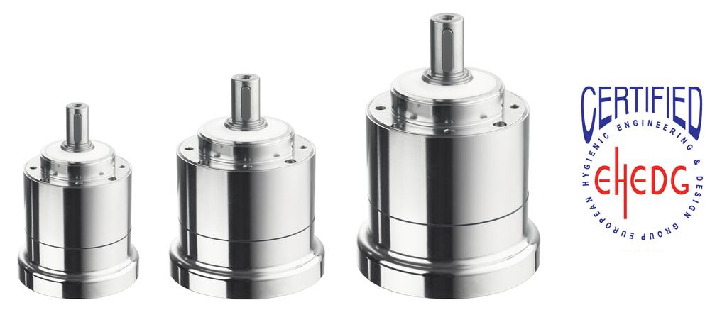
10 Guidelines and Standards 3 Guidelines and Standards In addition to the safety instructions mentioned in this manual, the general statutory and other rules and regulations for the prevention of accidents (e.g. personal protective equipment) and for environmental protection must be followed. CAUTION Note Personal injuries! The gear units are not products under the terms of the EC Machinery Directive. Operation of the gear units in machines or systems is only permitted once the machine or system manufacturers has provided evidence of CE conformity of the complete machine or system. EHEDG certification! The gear units of the series are certified according to Type EL Class I of the European Hygienic Engineering & Design Group (EHEDG). 10 Version: 1.3
11 Handling 4 Handling 4.1 Transport No special mode of transport is prescribed for the gear unit. Only by qualified personnel Only in the manufacturer's original packaging Avoid hard shocks. If the packaging is damaged check the gear unit and any accessories for visible damage. Inform the transport company and, if necessary, the manufacturer. Suspended loads may fall and cause serious injury or death. Never stand under suspended loads. WARNING Secure the gear unit with suitable fastenings (e.g. straps) prior to transport. Hard impacts, e.g. due to falling or dropping, may damage the gear unit. Use only lifting gear and load handling devices with sufficient load-bearing capacity. Attention Do not exceed the permitted lifting weight. Set the gear unit down slowly. 4.2 Packaging Recyclable cardboard with inserts Dispose of the packaging materials at designated disposal sites. Observe the relevant national disposal regulations 4.3 Storage The gear units must not be stored outdoors. The storage space must be adequately ventilated and dry. The gear units may only be stored in the original recyclable manufacturer's packaging. The gear units may only be stored in a horizontal position. Storage temperature: 0 C to +40 C in the original packaging Storage time: 2 years max. Possible damage to the gear unit seals Note If the gear units are stored at temperature ranges above 40 C or subjected to direct sunlight or ultraviolet light, the gear unit seals may become damaged. Storage temperatures of up to +35 C are permitted for a maximum of 2 weeks. However, please note that even short-term storage at such temperatures will result in premature ageing of the seals. Therefore, please check the seals before commissioning the gear unit. Version:
12 Handling 4.4 Maintenance / Cleaning Maintenance schedule Maintenance tasks During commissioning For the first Every 3 months Annually time, after 500 operating hours or 3 months Visual inspection x x x - Check the tightening torques x x - x Lubrication x - x x Maintenance tasks Visual inspection Check the entire gear unit for external damage. Check the entire gear unit for leaks. In the installation position, check that no foreign media (e.g. oil) accumulate on the drive and output shaft. Check the entire gear unit for corrosion. Note Further information regarding maintenance! For further information regarding maintenance of bearings or wearing parts please contact the Beckhoff applications department Check the tightening torques Check the tightening torque of the fastening screws on the gear housing. The tightening torque values can be found in chapter 7 "Mechanical installation [} 20]". Check the tightening torque of the set screws on the motor mounting. The tightening torque values can be found in chapter 7 "Mechanical installation [} 20]". 12 Version: 1.3
13 Handling Lubrication CAUTION Damage to the gear unit due to overheating of the components Inadequate lubrication of the components may lead to damage to the gear unit due to overheating. Calculate the usable life of the lubricant used Relubricate all relevant components as required Calculating the usable life of the lubricant To calculate the usable life of your lubricant, proceed as follows: Measure the temperature at the center of the housing in maximum operating state. The gear unit has reached thermal steady state when the temperature increase no longer exceeds 2 C per hour. CAUTION Damage to the gear box due to exceeding of the maximum permitted temperature If the maximum permitted temperature for the gear unit is exceeded, the gear unit may become damaged due to overheating. Ensure correct and adequate cooling, positioning and installation of the gear unit, in order to avoid exceeding the maximum permitted temperature. Switch off the machine / system as soon as the limit value is reached and the maximum temperature is exceeded. Add 10 C to the measured temperature. Now determine the usable life of the lubricant based on the table below. Version:
14 Handling Notes on the lubricant used Note Lubricant used All gear units are lubricated for life at the factory with a lithium soap grease based on mineral oil or a food-grade synthetic lubricating oil (oil type CLP PG) (see name plate). All bearings are lubricated for life at the factory. Further information on the lubricants is available directly from the manufacturer: Lubricants for the food industry (NSF-H1 registered) Klüber Lubrication München KG, Munich Phone: Klübersynth UH ; NSF H1 registration number: Klübersynth UH ; NSF H1 registration number: Klübersynth UH ; NSF H1 registration number: Commissioning after maintenance Clean the gear unit externally. Attach all safety devices. Perform a test run before releasing the gear unit again for operation. 14 Version: 1.3
15 Handling Cleaning agents and cleaning procedures Important notes Note Note Note Note Cleaning the gear unit! During operation, the pumping action of the gear unit can result in cleaning agent entering the inside of the gear unit. The gear unit may only be cleaned at standstill! Unsuitable cleaning agents may cause corrosion! The gear unit may only be cleaned with commercial cleaning agents. The cleaning agents may be fat-dissolving but must be non-aggressive! An overview of suitable cleaning agents can be found in section "Overview of materials [} 16]". Damage to seals! Cleaning the gear unit with a high-pressure water jet or a permanent present medium may damage the gear seals. Use a water jet with a maximum pressure of 28 bar. Removal media from the seal within 30 minutes. Residue-free cleaning Roughened surfaces cannot be cleaned without residues! Avoid scratching the gear unit or damaging the surface. It may no longer be possible to guarantee the effect of the HD design! Bacteria or similar matter may attach themselves to the surface! Version:
16 Handling Overview of materials This section contains a list of cleaning materials. During cleaning, the gear unit may be subjected to the substances listed below, in concentrations of up to 3%. Overview of permitted cleaning materials: Medium Acetyl chloride Aluminum chloride Ammonium chloride Chemical formula CH 3 COCI AICI 3-6H 2 O NH 4 CI Antimony trichloride SbCl 3 Barium chloride BaCl 2-2H 2 O Chlorine (including chlorine water, chloride of lime and chlorobenzene) Chlorosulfuric acid Hydrogen chloride gas Cl 2 HSO 3 Cl HCI Chromic acid CrO 3 Iron(III) chloride FeCl 3 Hydrogen fluoride HF Carnallite KCIMgCl 2-6H 2 O Aqua regia HCL + HNO 3 Magnesium chloride MgCl 2-6H 2 O Monochloroacetic acid Sodium chloride (common salt) Sodium hydroxide CH2CICOOH NaCl NaOH Sodium peroxide Na 2 O 2 Sulfuric acid H 2 SO 4 Tartaric acid COOH(CHOH) 2 COOH Tin II (IV) chloride SnCl 2-2H 2 O(SnCl 4 ) Overview of non-permitted cleaning materials: The substances listed below may not be used for cleaning the gear unit! Medium Aniline hydrochloride Chemical formula C 6 H 5 NH 2 HCI Bromine Br 2 Sodium hypochlorite (bleaching solution) NaCIO Mercury (II) chloride HgCl 2 Hydrochloric acid HCI 16 Version: 1.3
17 Handling 4.5 Disposal Note National regulations Observe the relevant national disposal regulations. Supplementary information on replacing the adapter plate and disassembly and disposal of the gear unit is available from our service department: The device should be disposed of by a certified disposal company. Addresses can be obtained from our service department. Metal parts can be sent for metal recycling. In accordance with the WEEE 2012/19/EU Directives we take old devices and accessories back for professional disposal, provided the transport costs are taken over by the sender. Send the devices with the note For disposal to: Beckhoff Automation GmbH & Co. KG Hülshorstweg Verl Version:
18 Product overview 5 Product overview 5.1 scope of delivery Check the completeness of the delivery against the delivery note. Missing parts or damage should be reported immediately in writing to the carrier, the insurance company and / or Beckhoff Automation. 5.2 name plate Item number Explanation 1 Note referring to hygienic design or the gear unit 2 Type key 3 Transmission ratio 4 Date of manufacture 5 Lubricant note 6 Country of manufacture 7 Serial number of the gear unit 5.3 type key 18 Version: 1.3
19 Technical description 6 Technical description 6.1 Gear unit configuration Gear units of the -HDV series are single- or multi-stage, low-backlash planetary gear units. The gear unit series is manufactured as version "M" (motor mounting) and can be used in any installation position. The output shaft bearing is designed for high breakdown torques and high axial forces. Motor centering via the sleeve with bearing prevents radial distortion of the motor. The gear unit can be adapted to different motor types using an adapter flange and a spacer sleeve. The gear units are manufactured to the ISO 9001 quality standard and lubricated for life. 6.2 Overview of gear components Technical drawing Pos. Gear components A Gear housing B Output shaft C Shaft seal at the output D O-ring seal E Adapter flange 6.3 General technical data Note The maximum permissible speeds and torques can be found in our catalog or on our website at Weight The table below shows the gear unit weights with a standard adapter flange. If a different adapter flange is used, the weight of the gear unit may differ by up to 10%. Gear size HDV stage (in kg) stage (in kg) Version:
20 Mechanical installation 7 Mechanical installation 7.1 Important notes CAUTION Damage to persons and devices Observe the general and special safety instructions. The gear unit can be used in any gear unit. Attention Assembly sequence Always follow the assembly sequence described below in order to avoid damage. The fastening screws are not included and must be provided by the customer. Pertinent information can be found in the individual assembly steps. Attention Compressed air may damage gear unit seals. Do not use compressed air for cleaning the gear unit. Attention In rare cases, leaks ("sweating") may occur at the drive in gear units with grease lubrication (see name plate). To avoid "sweating", we recommend sealing the areas between ð adapter plate and drive housing (gear unit) and ð adapter plate and motor ð with a surface seal adhesive (e.g. Loctite 573 or 574). ð For further information please contact our customer service. Clean the following components with a clean, lint-free cloth and a grease-dissolving, non-aggressive cleaning agent. Further information can be found in chapter "Cleaning agents and cleaning procedures [} 15]": all surfaces in contact with adjacent components Centering the motor shaft the internal diameter of the socket the spacer sleeve inside and outside In addition, check the contact surfaces for damage and foreign particles. 20 Version: 1.3
21 Mechanical installation 7.2 Mounting the motor on the gear unit The standard scope of supply of a -HDV series gear unit does not include a motor. If a motor is to be mounted on the gear unit it must: be a B5 type have a radial and axial run-out tolerance according to DIN EN and have a smooth shaft. For mounting a gear unit on a motor, we recommend Beckhoff servomotors of the AM8800 series. Note If a motor is included in the scope of supply, it is already mounted on delivery. No further installation is required. Attention Observe the safety instructions! Follow the information and safety instructions when mounting the gear unit on motor. Special safety instructions can be found in chapter 3.2 "Special safety instructions [} 8]" of this documentation. Instructions for mounting the motor on the gear unit Clean all components to ensure they are grease-free and check the motor and gear unit for damage prior to assembly. Mount the motor in vertical direction, if possible. If the motor shaft has a feather key, remove it. Insert a half wedge, if recommended by the manufacturer. Remove the screw plug (item A) from the mounting hole in the adapter flange (item B). Turn the sleeve (item C) until the set screw (item H) is accessible via the mounting hole. Place the seal between the motor (item D) and the adapter flange (item B). Push the motor shaft into the socket of the gear unit. The maximum permitted axial loads must not be exceeded. The motor shaft must slide easily. If this is not the case, the set screw should be loosened further. The slot in the spacer sleeve must be aligned with the groove (if present) in the motor shaft and the marking hole (item M). There must be no gap between the motor (item D) and the adapter flange (item B). Version:
 with a threadlocker (e.g. Loctite 243).")
22 Mechanical installation Technical drawing Pos. Name C H J K L M Sleeve Set screw Spacer sleeve Grooved motor shaft Smooth motor shaft Marking hole Coat the four screws (items F) with a threadlocker (e.g. Loctite 243). Mount the motor (item D) with the four screws (items F) at the adapter flange (item B). Tighten the set screw (item H) in the sleeve (item C). Screw in the screw plug (item A) of the adapter flange (item B). The screw sizes and specified tightening torques can be found in the following table. Width across flats [mm] Tightening torque [Nm] Gear size -HDV Internal sleeve dia. [mm] Width across flats of the set screw (item B) [mm] Tightening torque [Nm] Max. axial force [N] 7.3 Mounting the gear unit at the machine The gear housing has four threaded holes (items A) for connection with your machine. Thoroughly clean the output shaft, the centering devices and the contact surfaces. Coat the four screws (items C) with a threadlocker (e. g. Loctite 243). Attach the gear unit to the machine with the four mounting screws through the screw holes. Ensure that the machine surface is as smooth as possible. Mount the gear unit such that the screw plug points downwards. Use screw head seals (items B) and O-rings (items I and J) for sealing. Fittings on the output side Note The gear unit may be damaged by distortion! Distortion may occur during installation of the gear unit, resulting in damage to the gear unit. Mount gearwheels and toothed belt pulleys on the output shaft without using force. Never use a reaming or hitting action for mounting! Only use suitable tools for the installation! Ensure that the static axial forces permitted for the output bearings are not exceeded. 22 Version: 1.3

23 Mechanical installation Seal possible clearances during mounting on the output side. Ensure that the surfaces of the mounting parts are as smooth as possible. Only use screw head seals and O-rings for sealing purposes. Gear size -HDV Pitch circle Ø [mm] Screw size / strength class M5 / Ax M6 / Ax M10 / Ax Tightening torque [Nm] Version:
24 Technical data 8 Technical data 8.1 HDV015 Size 015 Transmission ratio i 1-stage 4 / 5 / 7 / 10 Max. acceleration torque (max cycles per hour) Rated torque at output (at n 1N ) EMERGENCY OFF torque (1000 x permitted during gear unit service life) Permitted mean drive speed (at T 2N and 20 C ambient temp.) 2-stage 16 / 20 / 25 / 35 / 50 / 70 / 100 T 2B Nm i = 4 / 5 / 7 / 16 / 20 / 25 / 35 / 50 / i = 10 / T 2N Nm i = 4 / 5 / 7 / 16 / 20 / 25 / 35 / 50 / i = 10 / T 2emerg. Nm 75 n 1N min -1 1-stage stage 3700 Max. drive speed n 1Max min Max. torsional backlash j t arcmin 1-stage 10 Max. axial force (relative to shaft/flange center output) Max. radial force (relative to shaft center at 100 min -1 ) 2-stage 15 F 2AMax N 500 / 1000 a) F 2RMax N 350 / 1600 a) Efficiency at full load η % 1-stage >97 2-stage Bearing life L h h Running noise (at n 1 = 3000 min -1 without load) >95 L PA db(a) 60 Max. permitted housing temperature C 90 Ambient temperature C -25 to +40 Lubrication Housing surface Direction of rotation Lubricated for life H1 electropolished Input and output side in the same direction Protection class IP 69 K b) Mass moment of inertia (relative to the drive) Bore diameter of the clamping hub Ø 14 a) reinforced bearings b) at 30 bar, ref. DIN Version: 1.3
25 Technical data Dimensional drawing HDV015 Version:
26 Technical data 8.2 HDV025 Size 025 Transmission ratio i 1-stage 4 / 5 / 7 / 10 Max. acceleration torque (max cycles per hour) Rated torque at output (at n 1N ) EMERGENCY OFF torque (1000 x permitted during gear unit service life) Permitted mean drive speed (at T 2N and 20 C ambient temp.) 2-stage 16 / 20 / 25 / 35 / 50 / 70 / 100 T 2B Nm i = 4 / 5 / 7 / 16 / 20 / 25 / 35 / 50 / i = 10 / T 2N Nm i = 4 / 5 / 7 / 16 / 20 / 25 / 35 / 50 / i = 10 / T 2emerg. Nm 190 n 1N min -1 1-stage stage 3400 Max. drive speed n 1Max min Max. torsional backlash j t arcmin 1-stage 10 Max. axial force (relative to shaft/flange center output) Max. radial force (relative to shaft center at 100 min -1 ) 2-stage 15 F 2AMax N 500 / 1500 a) F 2RMax N 350 / 2500 a) Efficiency at full load η % 1-stage >97 2-stage Bearing life L h h Running noise (at n 1 = 3000 min -1 without load) >95 L PA db(a) 63 Max. permitted housing temperature C 90 Ambient temperature C -25 to +40 Lubrication Housing surface Direction of rotation Lubricated for life H1 electropolished Input and output side in the same direction Protection class IP 69 K b) Mass moment of inertia (relative to the drive) Bore diameter of the clamping hub Ø 19 a) reinforced bearings b) at 30 bar, ref. DIN Version: 1.3
27 Technical data Dimensional drawing HDV025 Version:
28 Technical data 8.3 HDV035 Size 035 Transmission ratio i 1-stage 4 / 5 / 7 / 10 Max. acceleration torque (max cycles per hour) Rated torque at output (at n 1N ) EMERGENCY OFF torque (1000 x permitted during gear unit service life) Permitted mean drive speed (at T 2N and 20 C ambient temp.) 2-stage 16 / 20 / 25 / 35 / 50 / 70 / 100 T 2B Nm i = 4 / 5 / 7 / 16 / 20 / 25 / 35 / 50 / i = 10 / T 2N Nm i = 4 / 5 / 7 / 16 / 20 / 25 / 35 / 50 / i = 10 / T 2emerg. Nm 480 n 1N min -1 1-stage stage 2600 Max. drive speed n 1Max min Max. torsional backlash j t arcmin 1-stage 10 Max. axial force (relative to shaft/flange center output) Max. radial force (relative to shaft center at 100 min -1 ) 2-stage 15 F 2AMax N 1700 / 3000 a) F 2RMax N 1200 / 4250 a) Efficiency at full load η % 1-stage >97 2-stage Bearing life L h h Running noise (at n 1 = 3000 min -1 without load) >95 L PA db(a) 60 Max. permitted housing temperature C 90 Ambient temperature C -25 to +40 Lubrication Housing surface Direction of rotation Lubricated for life H1 electropolished Input and output side in the same direction Protection class IP 69 K b) Mass moment of inertia (relative to the drive) Bore diameter of the clamping hub Ø 24 a) reinforced bearings b) at 30 bar, ref. DIN Version: 1.3
29 Technical data Dimensional drawing HDV035 Version:

30 Commissioning 9 Commissioning 9.1 Important notes Damage to persons and devices Read up on the general and special safety instructions before starting the work. CAUTION Improper operation may result in damage to the gear unit. Please ensure that Attention ð the ambient temperature is not below -15 C and not above +40 C, and ð the operating temperature does not exceed +90 C. Avoid icing, which can damage the seals. For other operating conditions please contact our customer service. Do not exceed the operational limit values for the gear unit Only use the gear unit in a clean, dust-free and dry environment. DANGER Attention Serious risk of injury! Only specialist personnel with extensive knowledge in the areas of electrical engineering / drive technology are allowed to install and commission the equipment. Check that all live connection points are protected against accidental contact. Dangerous voltages can occur, up to 875 V DC. Due to the DC link capacitors, the DC link contacts "ZK+ and ZK- (DC+ and DC-)" and "RB+ and RB-" may be subject to dangerous voltages exceeding 875 V DC, even after the servo drive was disconnected from the mains supply. Wait 5 minutes for the AX AX5125 and AX520x; 15 minutes for the AX5140/AX5160/AX5172; 30 minutes for the AX5190/AX5191; 45 minutes for the AX5192/AX5193 after disconnecting, and measure the voltage at the DC links "ZK+ and ZK- (DC+ and DC-)". The device is safe once the voltage has fallen below 50 V. The surface temperature of the motor can exceed 100 C in operation. Check (measure) the temperature of the motor. Wait until the motor has cooled down below 40 C before touching it. Make sure that, even if the drive starts to move unintentionally, no danger can result for personnel or machinery. Overloading of the gear! With motor / gear combinations can in case of failure (mechanical blockage of the power train) due to high ratio, the gear will be overloaded. To prevent this, make sure that the motor rated torque and the motor peak torque is limited in the servo drive. Example: Motor rated torque / motor peak torque: 1 Nm / 5 Nm Gear rated torque / gear peak torque: 15 Nm / 24 Nm Gear ratio: i = 10 The motor rated torque is not limited. The motor peak torque is limited to 2,4 Nm. 30 Version: 1.3
31 Commissioning 9.2 Guide for commissioning the gear units The procedure for commissioning is described as an example. A different method may be appropriate or necessary, depending on the application of the equipment. Check the assembly and alignment of the motor and the gear unit. Check the drive components such as clutch, gear unit, belt pulley and gear unit for correct seating and setting (observe the permissible radial and axial forces). Check the wiring and connections at the motor, servo drive and gear unit. Check that the earthing is correct. Test the function of the holding brake, if used. (Apply 24V DC, the brake must release). Check whether the rotor of the motor revolves freely (release the brake, if necessary). Listen out for grinding noises from the motor and the gear unit. Check that all the required measures against accidental contact with live and moving parts have been carried out. Carry out any further checks which are specifically required for your system. Now commission the drive according to the commissioning instructions for the servo drive. In multi-axis systems, individually commission each drive unit (servo drive/motor(s)). During the installation and commissioning look out for chips or similar contaminants that may penetrate into the gear unit. Keep the work area clean and protect the gear unit from foreign objects. Penetration of dirt reduces the service life of the gear unit. Note Destruction of the gear unit due to maximal engine torque! Before commissioning, check that your configured max. engine torque does not destroy the gear unit. For further information, please refer to chapter 9.1: "Important notes [} 30]". Version:
32 Commissioning 9.3 Troubleshooting Attention Changed operating behavior A change in operating behavior may indicate existing damage of the gear unit or result in damage to the gear unit. Do not recommission the gear unit until the fault has been rectified. Personal injuries Troubleshooting may only be performed by trained personnel. CAUTION Error Possible cause Remedy Increased operating temperature The gear unit is not suitable for the purpose. Motor heats up the gear unit. Ambient temperature too high. Check the technical data. Check the wiring of the motor. Ensure adequate cooling. Change the motor. Ensure adequate cooling. Increased operating noises Distorted motor mounting Contact our service department. Bearing damage Gear tooth damage Toothed belt tension too high Lubricant loss Lubricant quantity too high Wipe off the leaking lubricant and continue to monitor the gear unit. Lubricant discharge should stop after a short time. Leaks Contact our service department. 32 Version: 1.3
33 Decommissioning 10 Decommissioning Damage to persons and devices Read up on the general and special safety instructions before starting the work. CAUTION Version:
34 Support and Service 11 Support and Service Beckhoff and their partners around the world offer comprehensive support and service, making available fast and competent assistance with all questions related to Beckhoff products and system solutions. Beckhoff's branch offices and representatives Please contact your Beckhoff branch office or representative for local support and service on Beckhoff products! The addresses of Beckhoff's branch offices and representatives round the world can be found on her internet pages: You will also find further documentation for Beckhoff components there. Beckhoff Headquarters Beckhoff Automation GmbH & Co. KG Huelshorstweg Verl Germany Phone: +49(0)5246/963-0 Fax: +49(0)5246/ Beckhoff Support Support offers you comprehensive technical assistance, helping you not only with the application of individual Beckhoff products, but also with other, wide-ranging services: support design, programming and commissioning of complex automation systems and extensive training program for Beckhoff system components Hotline: +49(0)5246/ Fax: +49(0)5246/ Beckhoff Service The Beckhoff Service Center supports you in all matters of after-sales service: on-site service repair service spare parts service hotline service Hotline: +49(0)5246/ Fax: +49(0)5246/ Version: 1.3
Highend planetary gear unit AG2300+SPxxx
 Operation Manual Highend planetary gear unit AG2300 Version: Date: 1.2 2017-07-26 Table of content Table of content 1 Foreword... 5 1.1 Notes on the documentation... 5 1.2 Documentation issue status...
Exchange of rollers from the XTS-Mover
 Service documentation for AT901-0050-0550 and AT9011-00x0-0550 Version: Date: 1.0 0.10.017 Table of contents Table of contents 1 Foreword... 5 1.1 Notes on the documentation... 5 1. Documentation issue
Economy planetary gear unit AG NPxxx
 Operation Manual compatible with planetary gear unit AG2210-+LPxxx Version: Date: 1.2 2018-03-28 Table of content Table of content 1 Foreword... 5 1.1 Notes on the documentation... 5 1.2 Documentation
Planetary gear unit AG1000-+PMxx
 Operating manual for stepper motors AS1000 Version: Date: 1.4 2018-03-15 Table of content Table of content 1 Foreword... 5 1.1 Notes on the documentation... 5 1.2 Documentation issue status... 6 1.3 Intended
Description AX5806. List of permissible motors. Version: Date:
 Description AX5806 List of permissible motors Version: 1.3.0 Date: 2017-11-15 Table of contents Table of contents 1 Foreword 3 1.1 Notes on the manual 3 1.1.1 Intendent audience 3 1.1.2 Origin of the
Documentation. Stepper motor AS1000. Version: Date:
 Documentation Version: Date: 3.6 2017-07-26 Documented motors 1 Documented motors AS10xx-xxxx Standstill torque [Nm] Rated current [A] AS1010-0000 0,38 1,0 0,056 Rotor moment of inertia [kg cm²] Resolution
Operation Manual. Stepper motor AS2000. Version: Date:
 Operation Manual Version: Date: 1.1 2019-01-25 Table of content Table of content 1 Foreword... 5 1.1 Notes on the documentation... 5 1.2 Documentation Issue Status... 6 1.3 Appropriate use... 6 2 Guidelines
alpha Value Line NP / NPL
 2022-D051411 04 alpha Value Line NP / NPL Operating Manual 2022-D051411 Revision: 04 NP / NPL Revision history Revision Date Comment Chapter 01 04.08.2014 new version all 02 05.10.2015 Renamed as NP; NPA
TP + ATEX MF-Version (grease lubricated)
") 2022-D020259 03 TP + ATEX MF-Version (grease lubricated) Operating Manual 2022-D020259 Revision: 03 Revision history Revision Date Comment Chapter 01 07.05.2009 New version All 02 26.11.2010 Technical
2022-D020259 03 TP + ATEX MF-Version (grease lubricated) Operating Manual 2022-D020259 Revision: 03 Revision history Revision Date Comment Chapter 01 07.05.2009 New version All 02 26.11.2010 Technical
Hygienic Design HDP + / HDV
 Hygienic Design Operating Manual 2022-D054446 Revision: 02 WITTENSTEIN alpha GmbH Walter-Wittenstein-Straße 1 D-97999 Igersheim Germany Customer Service department Deutschland WITTENSTEIN alpha GmbH service-alpha@wittenstein.de
TP + ATEX MA-Version (grease lubricated)
") 2022-D025379 04 TP + ATEX MA-Version (grease lubricated) Operating Manual 2022-D025379 Revision: 04 Revision history Revision Date Comment Chapter 01 13.12.2006 New version All 02 18.04.2007 Technical
2022-D025379 04 TP + ATEX MA-Version (grease lubricated) Operating Manual 2022-D025379 Revision: 04 Revision history Revision Date Comment Chapter 01 13.12.2006 New version All 02 18.04.2007 Technical
alpha Advanced Line SP + / SK + / SPK + / SC + / SPC + / HG +
 alpha Advanced Line SP + / SK + / SPK + / SC + / SPC + / HG + Operating Manual 2022-D062611 Revision: 01 Customer Service department WITTENSTEIN alpha GmbH Customer Service Walter-Wittenstein-Straße 1
Installation manual wall-mounted distributor
 EN Installation manual wall-mounted distributor EN 60003233 Issue 11.2016 2016-14-11 Table of contents 1 About this manual 3 1.1 Structure of the warnings 3 1.2 Symbols used 4 1.3 Signal words used 4 2
Toothed belt axis ELGC-TB-KF. Operating instruction [ ]
![Toothed belt axis ELGC-TB-KF. Operating instruction [ ]](/thumbs/83/87984161.jpg "Toothed belt axis ELGC-TB-KF. Operating instruction [ ]") Toothed belt axis ELGC-TB-KF en Operating instruction 8068220 2017-02 [8068222] Original instructions Identification of hazards and instructions on how to prevent them: Danger Immediate dangers which can
Toothed belt axis ELGC-TB-KF en Operating instruction 8068220 2017-02 [8068222] Original instructions Identification of hazards and instructions on how to prevent them: Danger Immediate dangers which can
Operating manual. Custom made gearboxes
 Operating manual Custom made gearboxes DSS-Nr. 100389549 DSS-Rev. 001 Datum 16.01.2018 Contents Contents 1 General information 3 1.1 Using the operating manual 3 1.2 Warnings in this operating manual 4
RADEX -N Composite Operating/Assembly instructions
 1 of 14 RADEX -N is a torsionally stiff flexible steel lamina coupling. It is able to compensate for shaft misalignment, for example caused by thermal expansion, etc. note ISO 101. Drawn: 0.05.15 Kb/Wig
Operating Instructions
 Operating Instructions Table of contents Table of contents... 1 1. Declaration... 1 2. Warranty and liability... 2 3. Gear description... 2 4. Gear types... 2 5. Safety... 3 5.1 General safety information...
Spindle axis ELGC-BS-KF. Operating instructions [ ]
![Spindle axis ELGC-BS-KF. Operating instructions [ ]](/thumbs/87/97202885.jpg "Spindle axis ELGC-BS-KF. Operating instructions [ ]") Spindle axis ELGC-BS-KF en Operating instructions 8067243 2017-01 [8067245] Original instructions Identification of hazards and instructions on how to prevent them: Danger Immediate dangers which can lead
Spindle axis ELGC-BS-KF en Operating instructions 8067243 2017-01 [8067245] Original instructions Identification of hazards and instructions on how to prevent them: Danger Immediate dangers which can lead
SP + The New Generation. MF Version (oil-lubricated) Operating manual and information on explosion protection. for use in area with explosion hazards
 Operating manual and information on explosion protection. for use in area with explosion hazards") SP + The New Generation MF Version (oil-lubricated) for use in area with explosion hazards Operating manual and information on explosion protection MOTOR TECHNOLOGY LTD MOTEC HOUSE, CHADKIRK BUSINESS PARK,
SP + The New Generation MF Version (oil-lubricated) for use in area with explosion hazards Operating manual and information on explosion protection MOTOR TECHNOLOGY LTD MOTEC HOUSE, CHADKIRK BUSINESS PARK,
Swing Piston Compressors and Vacuum Pumps
 Swing Piston Compressors and Vacuum Pumps NPK 018 AC Pressure NPK 018 DC Pressure NPK 018 AC Vacuum NPK 018 DC Vacuum Operating and Installation Instructions Read and observe these Operating and Installation
Installation manual portable distributors
 EN Installation manual portable distributors EN 60003206 Issue 11.2016 15/11/2016 Table of contents 1 About this manual 3 1.1 Structure of the warnings 3 1.2 Symbols used 4 1.3 Signal words used 4 2 Intended
Assembly and Maintenance Manual Type ASNU
 Assembly and Maintenance Manual Type ASNU Hatschekstr.36 69126 Heidelberg Germany Tel +49(0)6221 30470 Fax +49(0)6221 304731 info@stieber.de www.stieber.de Date of issue: 30.05.2018 GB Revision: 0 U:\EngUsers\!ProduktDoku\1AAA_Einbauerklaerung_Wartungsanleitung_Konformitaetserklaerung\1AAA_Wartungsanleitungen\Orginal_Worddatei\_ASNU.docx
ELGC-BS-KF. Spindle axis. Instructions Operating c [ ]
![ELGC-BS-KF. Spindle axis. Instructions Operating c [ ]](/thumbs/88/115778972.jpg "ELGC-BS-KF. Spindle axis. Instructions Operating c [ ]") ELGC-BS-KF Spindle axis Instructions Operating 8095590 8095590 2018-08c [8095592] Translation of the original instructions 2 Festo ELGC-BS-KF 2018-08c Table of contents 1 Further applicable documents...
ELGC-BS-KF Spindle axis Instructions Operating 8095590 8095590 2018-08c [8095592] Translation of the original instructions 2 Festo ELGC-BS-KF 2018-08c Table of contents 1 Further applicable documents...
Synchronous Servomotors AM8000 & AM8500
 Documentation Version: Date: 3.4 2017-11-27 Table of contents Table of contents 1 Foreword... 7 1.1 Notes on the documentation... 7 1.2 Documentation Issue Status... 8 1.3 Appropriate use... 9 2 Guidelines
Assembly and Maintenance Manual Type AS
 Assembly and Maintenance Manual Type AS Hatschekstr.36 69126 Heidelberg Germany Tel +49(0)6221 30470 Fax +49(0)6221 304731 info@stieber.de www.stieber.de Date of issue: 30.05.2018 GB Revision: 0 U:\EngUsers\!ProduktDoku\1AAA_Einbauerklaerung_Wartungsanleitung_Konformitaetserklaerung\1AAA_Wartungsanleitungen\Orginal_Worddatei\_AS.docx
Technical Documentation
 Technical Documentation Product manual Holding brake controller Document: 0198441113316 Edition: V1.00, 03.2006 Important information The drive systems described here are products for general use that
Mini slide EGSC-BS-KF. Operating instructions b [ ]
![Mini slide EGSC-BS-KF. Operating instructions b [ ]](/thumbs/87/95253800.jpg "Mini slide EGSC-BS-KF. Operating instructions b [ ]") Mini slide EGSC-BS-KF en Operating instructions 8081968 2017-11b [8081970] Translation of the original instructions EGSC-BS-KF-EN Identification of hazards and instructions on how to prevent them: Danger
Mini slide EGSC-BS-KF en Operating instructions 8081968 2017-11b [8081970] Translation of the original instructions EGSC-BS-KF-EN Identification of hazards and instructions on how to prevent them: Danger
Type 6213 EV, 6281 EV
 Type 6213 EV, 6281 EV 2/2-way solenoid valve 2/2-Wege-Magnetventil Électrovanne 2/2 voies Operating Instructions Bedienungsanleitung Manuel d utilisation 1 OPERATING INSTRUCTIONS The operating instructions
BoWex FLE-PA. BoWex FLE-PAC. KTR-N Sheet: Edition: EN 1 of BoWex FLE-PA / FLE-PAC Operating/Assembly instructions
 1 of 17 is a torsionally rigid flange coupling. It is able to compensate for shaft misalignment, for example caused by manufacturing inaccuracies, thermal expansion, etc. BoWex FLE-PA BoWex FLE-PAC Drawn:
MANN+HUMMEL ENTARON XD. Installation and Maintenance Manual. Version 0709
 MANN+HUMMEL ENTARON XD Installation and Maintenance Manual Version 0709 Contact information This installation and maintenance manual is a component part of the scope of delivery. It must be kept in a safe
CENTAX-SEC Series B Assembly and operating instructions CX BFS1-LE/SE-**-B M EN Rev. 1
 Assembly and operating instructions -**-B Contents 1 General remarks... 5 2 Safety... 6 2.1 Safety remarks... 6 2.1.1 Signal words... 6 2.1.2 Pictograms... 7 2.2 Qualification of deployed personnel...
Instruction Manual Hygienic Design Planetary Gearbox
 Instruction Manual Hygienic Design Planetary Gearbox Series: HLAE070 (1- & 2-stage) HLAE090 (1- & 2-stage) HLAE110 (1- & 2-stage) GB_ 100225294 / Rev. status "003" 1 Table of contents 1 Table of contents
Installation and Operating Manual for Tank and Equipment Cleaning Nozzles Series 5TM
 Installation and Operating Manual for Tank and Equipment Cleaning Nozzles Series 5TM 150 150 150 This instruction manual contains proprietary information which is protected by copyright laws. No part of
alpha Advanced Line DP + / DPK +
 alpha Advanced Line DP + / DPK + Operating Manual 2022-D057347 Revision: 02 WITTENSTEIN alpha GmbH Walter-Wittenstein-Straße 1 D-97999 Igersheim Germany Customer Service department Deutschland WITTENSTEIN
Operating and Maintenance Instructions. Abteilung TB, Schell Seite 1 8 SERIES 56
 Abteilung TB, Schell Seite 1 8 These instructions supersede all earlier instructions, in particular BWS 109-0 till BWS 109-3. For applications in areas with explosion hazard it is obligatory to observe
BA EN.=A. Ä.=A.ä. Operating Instructions. Gearbox. Type 12. / 52.
 BA 12.0028 EN.=A. Ä.=A.ä Operating Instructions Gearbox Type 12. / 52. Product key Gearboxes 1 2... Product group Product family Gearbox size Design Geared motors 1 2... Product group Product family Gearbox
BA 2039 SIMOGEAR. Adapter for gearbox BA General information and safety notes 1. Technical description. Installing 3.
 General information and safety notes 1 Technical description 2 SIMOGEAR Adapter for gearbox Operating Instructions Installing 3 Operation 4 Service and maintenance 5 Spare parts 6 Supplement to the SIMOGEAR
Servo motors AM8000 and AM8500
 Documentation Fan cooled Version: Date: 1.9 2017-09-18 Table of contents Table of contents 1 Foreword... 5 1.1 Notes on the documentation... 5 1.2 Documentation Issue Status... 6 1.3 Appropriate use...
Synchronous servomotor AM8100
 Documentation for compact drive technology Version: Date: 2.0 2018-03-06 Documented motors AM8100 AM8tuv-wxyz Documented motors AM8100 Standstill torque Standstill current Rated speed at rated supply
Type Operating Instructions. Bedienungsanleitung Manuel d utilisation. 2/2-way solenoid valve 2/2-Wege-Magnetventil Électrovanne 2/2 voies
 Type 6027 2/2-way solenoid valve 2/2-Wege-Magnetventil Électrovanne 2/2 voies Operating Instructions Bedienungsanleitung Manuel d utilisation 1 OPERATING INSTRUCTIONS The operating instructions contain
Assembly and Maintenance Manual Type RSBW
 Assembly and Maintenance Manual Type RSBW Hatschekstr. 36 69126 Heidelberg Germany Tel +49(0)6221 30470 Tel +49(0)6221 304731 info@stieber.de www.stieber.de Stieber Clutch Date of issue: 16/03/2017 GB
KeContact P20. User manual
 KeContact P20 User manual Comments to this manual In this manual you will find warnings against possible dangerous situations. The used symbols apply to the following meanings:!! WARNING! Indicates a potentially
Operating / Assembly Instructions Type A and CS Coupling
 Page: 1 of 14 Subject Index 1. Technical Data 2. Hints 2.1. General Hints 2.2. Warning and Safety Hints. 2.3. General Hints to Danger. 2.4. Proper use. 3. Storage. 4. Assembly. 4.1. Coupling components.
Type Operating Instructions. Bedienungsanleitung Manuel d utilisation. 2/2-way solenoid valve 2/2-Wege-Magnetventil Électrovanne 2/2 voies
 Type 5404 2/2-way solenoid valve 2/2-Wege-Magnetventil Électrovanne 2/2 voies Operating Instructions Bedienungsanleitung Manuel d utilisation Contents 1 Operating instructions...2 2 Intended use...3 3
Accessories for Wind Power Inverter WINDY BOY PROTECTION BOX 400 / 500 / 600
 Accessories for Wind Power Inverter WINDY BOY PROTECTION BOX 400 / 500 / 600 Installation Guide WBP-Box-IEN103320 IMEN-WBP-BOX Version 2.0 EN SMA Solar Technology AG Table of Contents Table of Contents
Planar surface gantry EXCM-30. Instructions. Mechanical installation b [ ]
![Planar surface gantry EXCM-30. Instructions. Mechanical installation b [ ]](/thumbs/91/106333591.jpg "Planar surface gantry EXCM-30. Instructions. Mechanical installation b [ ]") Planar surface gantry EXCM-30 Instructions Mechanical installation 804447 605b [8044434] EXCM-30 Translation of the original instructions LOCTITE is a registered trademark of its respective trademark holder
Planar surface gantry EXCM-30 Instructions Mechanical installation 804447 605b [8044434] EXCM-30 Translation of the original instructions LOCTITE is a registered trademark of its respective trademark holder
Type Operating Instructions. Bedienungsanleitung Manuel d utilisation
 Type 0131 2/2- or 3/2-way solenoid valve 2/2- oder 3/2-Wege-Magnetventil Électrovanne 2/2 ou 3/2 voies Operating Instructions Bedienungsanleitung Manuel d utilisation 1 OPERATING INSTRUCTIONS The operating
These operating instructions apply for: NCX 380 NCZ 300 NCX 480 NCZ 370 NCX 580 L NCZ 480 NCX 660 K NCZ 560 NCZ 660 NCZ 800
 Original instructions Operating Instructions for May 2010 Electric Internal Vibrators BA No. 1092E Series NCX and NCZ These operating instructions apply for: NCX 380 NCZ 300 NCX 480 NCZ 370 NCX 580 L NCZ
INSTRUCTION MANUAL. I/P Converter DSG BXXY3Z DSG BXXY4Z
 INSTRUCTION MANUAL I/P Converter DSG BXXY3Z DSG BXXY4Z Revision 2.0 3.626 016136 en Page 1/15 Should you have any questions concerning the I/P converter, please contact the Service Department of the Product
Electric cylinder ESBF-BS/-LS Operating instructions b [ ]
![Electric cylinder ESBF-BS/-LS Operating instructions b [ ]](/thumbs/81/84386573.jpg "Electric cylinder ESBF-BS/-LS Operating instructions b [ ]") Electric cylinder ESBF-BS/-LS-32... 100 en Operating instructions 8076295 2017-11b [8079297] Translation of the original instructions Symbols: Warning Installation and commissioning may only be performed
Electric cylinder ESBF-BS/-LS-32... 100 en Operating instructions 8076295 2017-11b [8079297] Translation of the original instructions Symbols: Warning Installation and commissioning may only be performed
Installation and Operational Instructions for ROBATIC -clutch Types _.0 and _.0 Sizes 3 7
 Please read these Installation and Operational Instructions carefully and follow them accordingly! Ignoring these Instructions may lead to malfunction or to clutch failure, resulting in damage to other
Swing Piston Compressors and Vacuum Pumps
 Swing Piston Compressors and Vacuum Pumps NPK 050 NPK 0100 Operating and Installation Instructions Read and observe these Operating and Installation Instructions! KNF Neuberger GmbH Alter Weg 3 D-79112
Product Information Overspeed governor GB 260
 Product Information GB 260 Copyright as per DIN ISO 16016. Manufactured under licence of C. Haushahn GmbH & Co. I Subject to modification. Published by SLC Sautter Lift Components GmbH & Co. KG Borsigstrasse
CENTAX-TEST Assembly and operating instructions 053C GB3. M EN Rev. 1
 Assembly and operating instructions Contents 1 General remarks... 5 2 Safety... 6 2.1 Safety remarks... 6 2.1.1 Signal words... 6 2.1.2 Pictograms... 7 2.2 Qualification of deployed personnel... 7 2.3
Operating Instructions
 BA 12.0028 450 298 EN Operating Instructions K12.0549 Typ Gearboxes 12.jjj 52.jjj Product key Gearboxes ➀ ➁ ➂ ➃ Product group Product family Gearbox size Design ➀ ➁ ➂ ➃ 12. 602. 20. 11 Geared motors ➀
Operating instructions Rotary actuators M135 M140 M150 M180. June 2012 / / EN
 Operating instructions Rotary actuators M135 M140 M150 M180 June 2012 / 118614 / EN General information General information Proof of amendment Copyright Subject to alterations Manufacturer Version Date
Turbocharger / A100-L Original assembly instructions English
 Assembly Instructions Turbocharger / A100-L Original assembly instructions English This document is valid for the A100-L series: A165-L, A170-L, A175-L, A180-L, A185-L, A190-L Purpose The assembly instructions
General operating manual for assembly, commissioning and maintenance of valves and hydraulic manifolds
 for assembly, commissioning and maintenance of valves and hydraulic manifolds 110210_general_operating_manual 07.2018 Table of contents Contents Page Important information 2 Important safety instructions
Documentation. Synchronous Servomotor AM3100. Version: 1.4 Date:
 Documentation Synchronous Servomotor AM3100 Version: 1.4 Date: 2012-04-20 Documented motors Drive Technology Documented motors AM3100 Standstill torque Standstill current Rated speed Rated supply voltage
FLENDER ZAPEX couplings. Type ZWT. Operating instructions BA 3505 EN 10/2011. FLENDER couplings
 FLENDER ZAPEX couplings Type ZWT Operating instructions FLENDER couplings FLENDER ZAPEX couplings Type ZWT Operating instructions Translation of the original operating instructions Technical data Notes
CENTAFLEX-K Assembly and operating instructions 014K S... M EN Rev. 1
 Assembly and operating instructions Contents 1 General remarks... 5 2 Safety... 6 2.1 Qualification of deployed personnel... 6 2.2 Warning notes... 6 2.2.1 Signal words... 6 2.2.2 Symbols... 7 2.3 Application
HV angle valve with single acting pneumatic actuator and closing spring (NC)
") Installation, Operating & Maintenance Instructions HV angle valve with single acting pneumatic actuator and closing spring (NC) Series 264 DN 100 160 mm (I. D. 4 6 ) This manual is valid for the following
Installation, Operating & Maintenance Instructions HV angle valve with single acting pneumatic actuator and closing spring (NC) Series 264 DN 100 160 mm (I. D. 4 6 ) This manual is valid for the following
Installation and Operational Instructions for EAS - HTL housed overload clutch Sizes 01 3 Type 490._24.0
 Please read these Operational Instructions carefully and follow them accordingly! Ignoring these Instructions may lead to malfunctions or to clutch failure, resulting in damage to other parts. Contents:
VARIFUEL MAINTENANCE AND REPAIR INSTRUCTIONS
 VARIFUEL2 200-120 MAINTENANCE AND REPAIR INSTRUCTIONS MOTORTECH Gas Regulation P/N 01.50.008-200-120-EN Rev. 06/2015 Copyright Copyright 2015 MOTORTECH GmbH. All rights reserved. Distribution and reproduction
Turbocharger / TPS-H Original assembly instructions English
 Assembly Instructions Turbocharger / TPS-H Original assembly instructions English This document is valid for the TPS-H series: TPS44-H, TPS48-H, TPS52-H Purpose TPS-H turbocharger The assembly instructions
Type 3320, Service Manual. Serviceanleitung Service Manuel
 Electromotive 2/2-way valve Elektromotorisches 2/2-Wege-Ventil Vanne électromotorisée à 2/2 voies Service Manual Serviceanleitung Service Manuel We reserve the right to make technical changes without notice.
Mod: KLD6-12/35XLAS-N
 12/2011 Mod: KLD6-12/35XLAS-N Production code: 1914070 INSTRUCTION MANUAL LOGIC LINE PLUS HOOD Reseller Stamp for Warranty Dear customer, Above all, thank you for choosing our product and we would like
Operating Instructions
 Operating Instructions BE2700 Brinkmann Immersions pumps of the series TA/STA/TAL/SAL901... 1303 Contents 1 General...1 2 Safety...2 3 Transport and storage...2 4 Description of product and accessories...2
Instructions for Fitting, Operating and Maintenance Canopy Door RE / (St.: )
") EN Instructions for Fitting, Operating and Maintenance Canopy Door 1 818 012 RE / (St.: 12.2010) 12.2010 ENGLISH Contents 1 Safety Instructions... 3 1.1 Qualified persons... 3 1.2 Symbols and signal words
EN Instructions for Fitting, Operating and Maintenance Canopy Door 1 818 012 RE / (St.: 12.2010) 12.2010 ENGLISH Contents 1 Safety Instructions... 3 1.1 Qualified persons... 3 1.2 Symbols and signal words
PG ALP. Low cost Planetary Gearbox. Product Manual E-V0505.doc
 PG ALP Low cost Planetary Gearbox Product Manual 05-01-06-E-V0505.doc Additional Supporting Documentation UL: 03-05-03 AC M2n - Product-Manual UL: 03-06-01 NX - Product-Manual UL: 03-01-02 AC R - Product-Manual
Installation, Operating & Maintenance Instructions. HV angle valve with pneumatic actuator single acting with closing spring (NC)
") Installation, Operating & Maintenance Instructions HV angle valve with pneumatic actuator single acting with closing spring (NC) Series 264 DN 10 50 mm (I. D. ⅜" 2") HV inline valve with pneumatic actuator
Installation, Operating & Maintenance Instructions HV angle valve with pneumatic actuator single acting with closing spring (NC) Series 264 DN 10 50 mm (I. D. ⅜" 2") HV inline valve with pneumatic actuator
FLENDER ARPEX Plate packs with close-fitting bolt connection. ARW-4 Sizes to Assembly instructions An 4239 en 12/2015.
 FLENDER ARPEX Plate packs with close-fitting bolt connection ARW-4 Sizes 101-4 to 292-4 Assembly instructions FLENDER couplings FLENDER ARPEX Plate packs with close-fitting bolt connection ARW-4 Sizes
Type Operating Instructions. Bedienungsanleitung Manuel d utilisation
 Globe control valve, pneumatically operated Actuator sizes 40 mm - 125 mm, Nominal diameter DN10-65 Kolbengesteuertes Geradsitzventil Antriebsgrößen 40 mm - 125 mm, Nennweiten DN10-65 Vanne à siège droit
Type 5411, Operating Instructions. Bedienungsanleitung Manuel d utilisation
 Type 5411, 5413 3/2 or 4/2 way solenoid valve 3/2 oder 4/2-Wege-Magnetventil Électrovanne 3/2 ou 4/2 voies Operating Instructions Bedienungsanleitung Manuel d utilisation 1 THE OPERATING INSTRUCTIONS The
M-Version. TP & TP-High Torque. Operating Manual. TP Low-backlash planetary gear. S-Version. K-Version
 M-Version TP & TP-High Torque S-Version K-Version TP Low-backlash planetary gear Operating Manual Operating Manual TP 1 Contents 1 Contents... 2 1.1 Service Contact... 2 2 General Information... 3 2.1
Rack and pinion axis EHMH. Operating instructions [ ]
![Rack and pinion axis EHMH. Operating instructions [ ]](/thumbs/74/69745791.jpg "Rack and pinion axis EHMH. Operating instructions [ ]") Rack and pinion axis EHMH en Operating instructions 8076544 2017-09 [8076555] Translation of the original instructions GDCP-EHMH-EN Symbols used: Caution Hazards that can cause minor injuries Note Material
Rack and pinion axis EHMH en Operating instructions 8076544 2017-09 [8076555] Translation of the original instructions GDCP-EHMH-EN Symbols used: Caution Hazards that can cause minor injuries Note Material
Type 0283, Operating Instructions. Bedienungsanleitung Manuel d utilisation. 2/2-way solenoid valve 2/2-Wege-Magnetventil Électrovanne 2/2 voies
 Type 0283, 0293 2/2-way solenoid valve 2/2-Wege-Magnetventil Électrovanne 2/2 voies Operating Instructions Bedienungsanleitung Manuel d utilisation Contents 1 The operating instructions...2 2 Intended
CO 3-WAY PNEUMATIC VALVE INSTRUCTION MANUAL 2080
 CO 3-WAY PNEUMATIC VALVE INSTRUCTION MANUAL 2080 STI S.r.l has taken every care in collecting and verifying the documentation contained in this Instruction Manual. The information herein contained are
Operating manual. original operating manual. HDA eco Box 12/24V DC Automatic Dispenser. Translation of the. Item No.:
 Operating manual HDA eco Box 12/24V DC Automatic Dispenser Item No.: 110 500 900 Translation of the original operating manual Important! Copyright The operating manual is always to be read before commissioning
Operating and Maintenance Manual. for. HADEF overhead crane. as jointed crane TA
 5.52.714.00.1.0 Edition 03.2004 GB Operating and Maintenance Manual for HADEF overhead crane as jointed crane TA Subject to changes. 1 HADEF Table of Contents 1 General Page 3 2 Product description Page
PKF(closed design) Operating Manual. M-Version. PKF Low-backlash planetary bevel gear reducer with hollow output shaft
 Operating Manual. M-Version. PKF Low-backlash planetary bevel gear reducer with hollow output shaft") (closed design) M-Version Low-backlash planetary bevel gear reducer with hollow output shaft 1 Contents 1 Contents 1 1.1 Service Contact 1 2 General Information 2 2.1 Description, Designations 2 2.2 Whom
(closed design) M-Version Low-backlash planetary bevel gear reducer with hollow output shaft 1 Contents 1 Contents 1 1.1 Service Contact 1 2 General Information 2 2.1 Description, Designations 2 2.2 Whom
Operating Instructions
 Resistance Thermometer Clamp-on technology for temperature measurement on pipes, Type Series GA261x Operating Instructions 1 General Information... 2 1.1 General Safety Notes... 2 1.2 Intended Use... 2
Pressure relief valve
 Pressure relief valve Operating manual Series DHV 712 Version BA-2015.10.20 EN Print-No. 300 510 TR MA DE Rev001 ASV Stübbe GmbH & Co. KG Hollwieser Straße 5 32602 Vlotho Germany Phone: +49 (0) 5733-799-0
Type Operating Instructions. Bedienungsanleitung Manuel d utilisation. 2/2-Way Solenoid Valve 2/2-Wege-Magnetventil Électrovanne à 2/2 voies
 Type 5282 2/2-Way Solenoid Valve 2/2-Wege-Magnetventil Électrovanne à 2/2 voies Operating Instructions Bedienungsanleitung Manuel d utilisation 1 OPERATING INSTRUCTIONS The operating instructions contain
Installation, Operating & Maintenance Instructions. UHV gate valve with pneumatic actuator. Series 108 DN mm (I. D. 2½ 8 )
") Installation, Operating & Maintenance Instructions UHV gate valve with pneumatic actuator Series 108 DN 63 200 mm (I. D. 2½ 8 ) This manual is valid for the following product ordering numbers: 108.. -.
Installation, Operating & Maintenance Instructions UHV gate valve with pneumatic actuator Series 108 DN 63 200 mm (I. D. 2½ 8 ) This manual is valid for the following product ordering numbers: 108.. -.
Installation, Operating & Maintenance Instructions. HV gate valve with pneumatic actuator. Series 110 DN mm (I. D.
 Installation, Operating & Maintenance Instructions HV gate valve with pneumatic actuator Series 110 DN 250 320 mm (I. D. 10" 12") This manual is valid for the following product ordering numbers: 11048-.
EPS 16 ATEX 1121 X, IECEx EPS X Solenoid coil Type 06xx Magnetspule Typ 06xx Bobine magnétique Type 06xx. Operating Instructions
 , IECEx EPS 16.0053X Solenoid coil Type 06xx Magnetspule Typ 06xx Bobine magnétique Type 06xx Device with II 2G/D Ex approval Geräte mit II 2G/D Ex Zulassung Appareils avec mode de protection II 2G/D Ex
Installation and Service Instructions (Translation of the Original Instructions) SV120. C _EN 11/2009 Rev.0
 SV120. C _EN 11/2009 Rev.0") Installation and Service Instructions (Translation of the Original Instructions) SV20 Introduction Carefully read these Installation and Service Instructions prior to the installation and start of operation
Installation and Service Instructions (Translation of the Original Instructions) SV20 Introduction Carefully read these Installation and Service Instructions prior to the installation and start of operation
VARIFUEL MAINTENANCE AND REPAIR INSTRUCTIONS
 VARIFUEL2 140-65 MAINTENANCE AND REPAIR INSTRUCTIONS MOTORTECH Gas Regulation P/N 01.50.008-140-65-EN Rev. 06/2015 Copyright Copyright 2015 MOTORTECH GmbH. All rights reserved. Distribution and reproduction
Bowl feeder WV401-1 / Translation of operating and installation instructions
 Bowl feeder WV401-1 / 402-1 Translation of operating and installation instructions Copyright by Afag GmbH This operation instruction applies to: Bowl feeder WV401-1 Bowl feeder WV402-1 Type 230 V / 50
EPS 16 ATEX 1072 X, IECEx EPS X. Operating Instructions. Solenoid coil Type AC19 Magnetspule Typ AC19 Bobine magnétique Type AC19
 , IECEx EPS 16.0030X Solenoid coil Type AC19 Magnetspule Typ AC19 Bobine magnétique Type AC19 Device with II 2G/D Ex approval Geräte mit II 2G/D Ex Zulassung Appareils avec mode de protection II 2G/D Ex
SPARKSCAN1 HIGH VOLTAGE CLAMP OPERATING MANUAL
 SPARKSCAN1 HIGH VOLTAGE CLAMP OPERATING MANUAL MOTORTECH Tools & Test Equipment for Ignition Systems P/N 01.10.019 Rev. 01/2013 Copyright Copyright 2012 MOTORTECH GmbH. All rights reserved. Distribution
User Guide. Lubricus Lubrication System LUB-D1/LUB-D2/LUB-D3/LUB-D4 (24 VDC)
") User Guide Lubricus Lubrication System LUB-D1/LUB-D2/LUB-D3/LUB-D4 (24 VDC) version 04/2013 Content General Information 3 Warning 3 Scope of Supply 3 Overview 3 General safety details 4 Intended use 4
User Guide Lubricus Lubrication System LUB-D1/LUB-D2/LUB-D3/LUB-D4 (24 VDC) version 04/2013 Content General Information 3 Warning 3 Scope of Supply 3 Overview 3 General safety details 4 Intended use 4
Original Operating Manual
 2010-10-29 Original Operating Manual Control Panel Comfort for Pedelecs Series 4313 Save for future use! Marquardt GmbH Schlossstraße 16 78604 Rietheim-Weilheim E-mail: marquardt@marquardt.de Website:
Operating instructions
 Operating instructions Digital tank contents indicator DTA 10 DTA 10 DTA 10 0 4.0 m fuel oil 0 3.5 m water Read instructions before using device! Observe all safety information! Keep instructions for future
Turbocharger / VTR..0, VTR..1 Original assembly instructions English
 Assembly Instructions Turbocharger / VTR..0, VTR..1 Original assembly instructions English This document is valid for the VTR..0/..1 series: VTR160, VTR200, VTR250, VTR320, VTR400 VTR161, VTR201, VTR251,
INSTALLATION, SERVICE AND MAINTENANCE INSTRUCTIONS Y-FILTER 83700
 INSTALLATION, SERVICE AND MAINTENANCE INSTRUCTIONS Y-FILTER 83700 11.106.32.0001 INOXPA, S.A. c/telers, 54 Aptdo. 174 E-17820 Banyoles Girona (Spain) Tel. : (34) 972-57 52 00 Fax. : (34) 972-57 55 02 email:
INSTALLATION, SERVICE AND MAINTENANCE INSTRUCTIONS Y-FILTER 83700
 INSTALLATION, SERVICE AND MAINTENANCE INSTRUCTIONS Y-FILTER 83700 11.106.32.0001 INOXPA, S.A. c/telers, 54 Aptdo. 174 E-17820 Banyoles Girona (Spain) Tel. : (34) 972-57 52 00 Fax. : (34) 972-57 55 02 email:
CENTAFLEX-H Assembly and operating instructions 008H /3000 M EN Rev
 008H-00400-1000/3000-1000 -3000-1000 -3000 Contents 1 General remarks... 5 2 Safety... 6 2.1 Safety remarks... 6 2.1.1 Signal words... 6 2.1.2 Pictograms... 7 2.2 Qualification of deployed personnel...
Oil-free piston compressors KK and piston vacuum pumps KV
 Oil-free piston compressors KK and piston vacuum pumps KV Installation and Operating Instructions 0678106030L02 1707V003 Contents Important information 1 About this document 2 1.1 Warnings and symbols