CENTAX-TEST Assembly and operating instructions 053C GB3. M EN Rev. 1
|
|
|
- Christopher Hoover
- 5 years ago
- Views:
Transcription

1 Assembly and operating instructions
2 Contents 1 General remarks Safety Safety remarks Signal words Pictograms Qualification of deployed personnel Intended application Application not in compliance with the intended use Delivery, transport, storage and disposal Delivery Transport Storage Storage location Storage of couplings / flexible elements Disposal Technical description Characteristics Specifications Alignment of the units being connected Axial alignment Radial alignment Angular alignment Mounting General assembly instructions Mounting overview Mounting the adapter (if existing) Mounting the adapter with cross-serration Mounting the adapter Aligning the units Mounting the pre-mounted coupling After completed mounting Operation Operating faults, root causes and remedy Admissible overall misalignment of the coupling Care and maintenance Work to be performed Cleaning the coupling...25 CENTA Antriebe Kirschey GmbH 2 / 30
3 8.1.2 Visual inspection of the coupling Inspection of the screw connections Replacing defective parts Dismantling General dismantling instructions Dismantling the pre-mounted coupling Dismantling the adapter (if necessary) Reassembling the coupling Wearing and spare parts Annex CENTA data sheet D (lubricated screw connections) CENTA data sheet D Declaration of incorporation according to the EC Machinery Directive 2006/42/EC, Appendix II B...30 CENTA Antriebe Kirschey GmbH 3 / 30
4 Index of illustrations Fig. 5-1 Axial misalignment Fig. 5-2 Radial misalignment Formula 5-3 Radial alignment tolerance K R max Fig. 5-4 Angular misalignment Fig. 6-1 Example: 053C GB Fig. 6-2 Mounting the adapter with cross-serration Fig. 6-3 Mounting the adapter Fig. 6-4 Mounting the pre-mounted coupling Index of tables Table 2-1 Shape and size of ventilation holes... 8 Table 7-1 Troubleshooting table Index of formulas CENTA Antriebe Kirschey GmbH 4 / 30
5 1 General remarks These assembly and operating instructions form a constituent part of the coupling delivery and must be kept in an easily accessible place at all times. CENTA products are developed and produced to quality standard DIN EN ISO 9001:2000. In the interests of further development, CENTA reserves the right to make technical changes. IMPORTANT CENTA is unable to accept liability for damage and operating faults caused by failure to observe the operating instructions. These operating instructions are protected under copyright to CENTA Antriebe Kirschey GmbH. In case of technical questions, please enquire with our head office: CENTA Antriebe Kirschey GmbH Bergische Strasse Haan GERMANY Phone Fax centa@centa.de CENTA Antriebe Kirschey GmbH 5 / 30
6 2 Safety The purpose of these operating instructions is to enable users to: use the coupling safely and correctly maximize efficiency ensure that care and maintenance are carried out correctly For this reason, these operating instructions must be thoroughly read and understood prior to work on and with the coupling. Injury and material damage can occur as a result of: Failure to adhere to the safety and accident prevention regulations valid at the relevant installation site The safety and accident prevention regulations valid at the installation site in question must be adhered to when performing any of the tasks described in these operating instructions. 2.1 Safety remarks In these operating instructions, safety remarks are indicated by a pictogram and a signal word Signal words The following signal words are used in the safety remarks: DANGER Denotes the immediate threat of danger. If not prevented, fatal or extremely serious injuries can result. Denotes a potentially dangerous situation. If not prevented, fatal or extremely serious injuries can result. CAUTION Denotes a potentially dangerous situation. If not prevented, minor injuries and/damage to property may result. IMPORTANT Denotes application tips and particularly useful information. This is not a signal word denoting a dangerous or damaging situation. CENTA Antriebe Kirschey GmbH 6 / 30


7 2.1.2 Pictograms Possible pictograms in the safety precautions: Warning of a hazardous area Do not switch Use protective gloves Use protective goggles 2.2 Qualification of deployed personnel All the work described in these operating instructions may only be performed by authorized persons with adequate training and instruction. Injury and material damage can occur as a result of: Work at the coupling which is not described in these instructions Only carry out work which is described in these operating instructions. 2.3 Intended application Injury and material damage can occur as a result of: Application not in compliance with the intended use The couplings are intended exclusively for use in accordance with the relevant design. They may only be used under the specified conditions. CENTA Antriebe Kirschey GmbH 7 / 30
8 Injuries can occur as a result of: Contact with rotating parts Shield the coupling in accordance with the applicable accident prevention regulations with an enclosure. Exception: The coupling is encased by the driving and driven units. The scope of delivery provided by CENTA does not include a protective enclosure. This enclosure must fulfil the following criteria: Provide protection against persons gaining access to rotating parts Restrain any rotating parts which may be work loose Guarantee sufficient ventilation for the coupling This enclosure must be made of stable steel components. In order to ensure adequate ventilation for the coupling, the enclosure must be fitted with regular openings. For safety reasons, these openings must not exceed the dimensions outlined in table 2-1. Component Circular openings [mm] Rectangular openings [mm] Top of the enclosure Ø 8 8 Side elements of the enclosure Ø 8 8 Table 2-1 Shape and size of ventilation holes The enclosures must be positioned a minimum of 15 mm distant from rotating parts. The enclosure must be electrically conductive and be included in the equipotential bonding. Before commencing long-term operation, the plant must successfully complete a test run. CENTA Antriebe Kirschey GmbH 8 / 30
9 2.4 Application not in compliance with the intended use Injury and material damage can occur as a result of: Inadmissibly high torque Inadmissibly high or low speeds Exceeding the specified ambient temperature Inadmissible ambient medium Inadmissible coupling enclosure Exceeding the admissible overall misalignment values Only use the coupling for the specified application. CENTA bears no liability for damage resulting from application not in compliance with the intended use of the equipment. Should there be a change of plant parameters, the coupling design must be reviewed by CENTA (address see chapter 1). CENTA Antriebe Kirschey GmbH 9 / 30
10 3 Delivery, transport, storage and disposal 3.1 Delivery After delivery, the coupling: 3.2 Transport must be checked for completeness and correctness of the delivery. must be examined for possible transport damage (which must be reported immediately to the carrier). CAUTION Injury and material damage can occur as a result of: Incorrect transportation of couplings Ensure that the coupling is correctly transported. CAUTION Material damage to coupling components can occur as a result of: Contact with sharp-edged objects Protect coupling components for transportation. Only hoist coupling components with nylon belts or ropes. Always cushion parts when supporting them from below. Following transportation damage: 3.3 Storage Check the coupling carefully for damage. Consult the manufacturer (Address see chapter 1). CAUTION Material damage to elastic elements and rubber parts can occur as a result of: Incorrect storage These parts must be stored laid flat and so they cannot distort, and protected from ozone, heat, light, moisture and solvents. IMPORTANT Rubber parts are marked where possible with their production date. From this date, they may only be stored for a maximum of 5 years. CENTA Antriebe Kirschey GmbH 10 / 30
11 3.3.1 Storage location Requirements imposed on the storage location: Moderately ventilated and low in dust Dry (max. 65% humidity) Temperature stabilized (-10 C to +25 C) Free of ozone-producing devices such as light sources and electric motors Free of UV light sources and direct sunlight Do not store solvents and disinfectants, fuels or lubricants, acids, chemicals etc. in the same location For more details, refer to DIN Storage of couplings / flexible elements Unpack the parts. Check the packaging for damage. Replace if necessary. Check that the wax protection on steel components is intact. If necessary, patch or renew. Package the parts (for prolonged periods of storage, enclose desiccant and weld into film). Place the parts into storage. 3.4 Disposal RECYCLING Ensure safe, environmentally responsible disposal of operating supplies and exchange parts. For this, locally provided recycling facilities and regulations must be utilized. For disposal, the coupling parts must be separated where possible and sorted according to material type. CENTA Antriebe Kirschey GmbH 11 / 30
12 4 Technical description 4.1 Characteristics couplings: are highly flexible test bed couplings for high speeds, for optimum test conditions based on a highly flexible rubber element, combinable with homokinetic joints, carden shafts, slip joints, etc., as demanded by test requirements are extremely adaptable designed with torsionally flexibility dampen torsional vibrations and shocks compensate axial, tagential and angular misalignments are suitable for high speed ranges and long-term tests are available in any length and mounting dimensions to be adaptable to the respective test situation are easy to mount because slip joints and elements can be shifted in axial direction are optionally available as customised solutions for automatic docking onto combustion engines 4.2 Specifications The specifications can be found in the catalogue and the dimensions in the installation drawing. CENTA Antriebe Kirschey GmbH 12 / 30
13 5 Alignment of the units being connected IMPORTANT Align the units during the assembly. Align the units that are to be connected as accurately as possible. In this way, a long service life for the coupling and maximum operating misalignment values can be achieved. The overall misalignment is composed of the misalignment and the operating misalignment. The permissible overall misalignment values can be found in chapter 7.2 and must not be exceeded. All permissible alignment tolerances apply to arrangements at operating temperatures. If the arrangement would be aligned at a different temperature, there would be additional deviations in the arrangement, which were produced by the difference between the aligning and operating temperature. For alignment, this has to be taken into account. After completion of assembly, check the alignment of the coupling again and correct, if necessary. CENTA Antriebe Kirschey GmbH 13 / 30
14 5.1 Axial alignment Fig. 5-1 Axial misalignment Item Info Designation Remark 7 Adapter See installation drawing A Flywheel Costumer part B Flange Costumer part Determine the axial misalignment (see Fig. 5-1). Take installation length L from the installation drawing. Align the units (installation dimension = L± K A max ). Permissible axial alignment tolerance: K A max =1.0 mm CENTA Antriebe Kirschey GmbH 14 / 30
15 5.2 Radial alignment Fig. 5-2 Radial misalignment Item Info Designation Remark 7 Adapter See installation drawing A Flywheel Costumer part B Flange Costumer part CAUTION Material damage to elastically installed engines can occur as a result of: Disregard to which extent the engine mounts may settle during alignment During vertical alignment, take into account the extent by which the engine mounts settle. Please enquire about specifications for the degree of settling from the engine manufacturer or engine mounts manufacturer. Determine the radial misalignment (see Fig. 5-2). Take installation length L from the installation drawing. The permissible radial alignment tolerance K R max should be calculated according to formula below: Formula 5-1 Radial alignment tolerance K R max Align the units (calculated deviation K R max ). CENTA Antriebe Kirschey GmbH 15 / 30
16 5.3 Angular alignment Fig. 5-3 Angular misalignment Item Info Designation Remark 7 Adapter See installation drawing A Flywheel Costumer part B Flange Costumer part Determine the angular misalignment (see Fig. 5-3). Align the units (calculated deviations K W1 max and K W2 max ). The angular deflection has to be checked at each flange separately. Permissible angular alignment tolerance: (A) K W1 max =0.05 (7/B) K W2 max =0.2 CENTA Antriebe Kirschey GmbH 16 / 30
17 6 Mounting 6.1 General assembly instructions Any work method which impairs the safety of the coupling is prohibited. The user undertakes to notify the manufacturer immediately of any changes occurring at the coupling which could impair safety (address see chapter 1). Injuries can occur as a result of: Contact with rotating parts Before starting work at the coupling, switch off the plant and secure against unintentional start-up. Injury and material damage can occur as a result of: Assembly of the coupling in the wrong sequence Only ever assemble the coupling in the described sequence. Injury and material damage can occur as a result of: Falling coupling components Secure coupling components against falling to the floor. CAUTION Material damage to coupling components can occur as a result of: Contact with sharp-edged objects Protect coupling components for transportation. Only hoist coupling components with nylon belts or ropes. Always cushion parts when supporting them from below. CAUTION Material damage can occur as a result of: Soiled joint surfaces The surfaces that are to be joined must be free of dirt, preservatives and lubricants. CENTA Antriebe Kirschey GmbH 17 / 30
18 CAUTION Material damage to coupling components can occur as a result of: Anaerobic adhesives (e.g. Loctite) used for screw locking This type of screw locking medium may not be in contact with rubber parts. IMPORTANT Screw preparation and tightening torque levels in accordance with CENTA data sheet D (see chapter 11.1). Use suitable lifting devices for assembly. The following assembly stages are described for coupling 053C GB3.. Part illustration and marking may different slightly from installation drawing and delivery state. CENTA Antriebe Kirschey GmbH 18 / 30
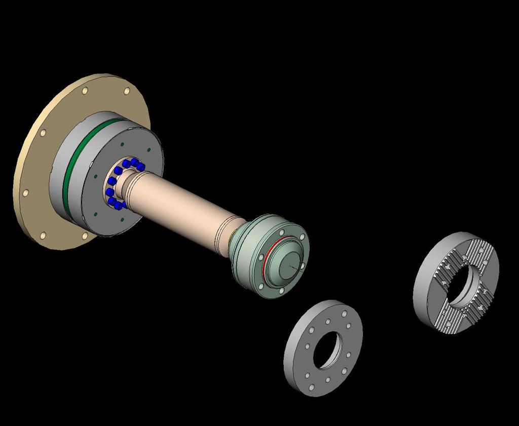
19 6.2 Mounting overview The following figures show examples of possible design. Fig. 6-1 Example: 053C GB3. Item Info Designation Remark 7 Adapter If scope of supply C Pre-mounted coupling IMPORTANT This assembly instruction describes the mounting of several design. Mount the coupling as appropriate for the supplied design (see installation drawing). Mount the coupling as appropriate for the supplied design, according to the sequence described below. For supplied design and the parts built-in, see installation drawing. Mounting the adapter (7), see chapter 6.3. Aligning the units, see chapter 5. Mounting the pre-mounted coupling (C), see chapter 6.4. After completed mounting, see chapter 6.5. CENTA Antriebe Kirschey GmbH 19 / 30
20 6.3 Mounting the adapter (if existing) Mount the adapter (7) as appropriate for the supplied design (see installation drawing): Mounting the adapter with cross-serration, see chapter Mounting the adapter, see chapter Mounting the adapter with cross-serration Fig. 6-2 Mounting the adapter with cross-serration Item Info Designation Remark 7 Adapter 30 Screw If ordered B Flange Customer part Push the adapter (7) into the toothing of the flange (B). Screw the adapter (7) to the flange (B) using the screws (30). CENTA Antriebe Kirschey GmbH 20 / 30
21 6.3.2 Mounting the adapter Fig. 6-3 Mounting the adapter Item Info Designation Remark 7 Adapter 30 Screw If ordered B Flange Customer part Push the adapter (7) onto/into the centring of flange (B). Screw the adapter (7) to the flange (B) using the screws (30). 6.4 Aligning the units Align the units to be connected (see chapter 5). CENTA Antriebe Kirschey GmbH 21 / 30
22 6.5 Mounting the pre-mounted coupling Fig. 6-4 Mounting the pre-mounted coupling Item Info Designation Remark Joint CV-joint 4 Adapter 7 Adapter If scope of supply 8 Screw ISO M.. 33 Screw If ordered A Flywheel flange Customer part B Flange Customer part C Pre-mounted coupling CENTA Antriebe Kirschey GmbH 22 / 30
23 Push the joint (2.1.3) towards the adapter (4). Position the pre-mounted coupling (C) in the installation space and support. Push the flange (4) of the pre-mounted coupling (C) into the centring of the flywheel flange (A). Screw the flange (4) to the flywheel flange (A) using the screws (33). Push the joint (2.1.3) close to the adapter/flange (7/B). Screw the joint (2.1.3) to the adapter/flange (7/B) using the screws (8). 6.6 After completed mounting Injury and material damage can occur as a result of: Loose screw connections Before commissioning, the tightening torque levels of all screws must be checked and corrected if necessary. Before commencing long-term operation, the plant must successfully complete a test run. CENTA Antriebe Kirschey GmbH 23 / 30
24 7 Operation Injury and material damage can occur as a result of: Worn coupling components If the running noises change and/or vibrations occur turn the plant off immediately. Determine the fault and its root cause, and remedy. The troubleshooting process is simplified by the table in the next chapter. On principle in case of a fault, an analysis of the entire plant should be performed. 7.1 Operating faults, root causes and remedy Faults Running noises or vibrations in the plant Breakage of the rubber element Possible root causes Alignment error Loose screws Alignment error Inadmissibly high torque Remedy 1. Switch off the plant 2. Check alignment, correct if applicable 3. Trial run 1. Switch off the plant 2. Check alignment, correct if applicable 3. Check screw torque levels and correct if necessary 4. Trial run 1. Switch off the plant 2. Exchange defective parts 3. Check alignment, correct if applicable 4. Trial run 1. Switch off the plant 2. Exchange defective parts 3. Check alignment, correct if applicable 4. Trial run Table 7-1 Troubleshooting table In case of uncertainty or if you have questions, please contact our head office (address see chapter 1). 7.2 Admissible overall misalignment of the coupling The overall misalignment values can be found in the catalogue. CENTA Antriebe Kirschey GmbH 24 / 30
25 8 Care and maintenance Injuries can occur as a result of: Contact with rotating parts Before starting work at the coupling, switch off the plant and secure against unintentional start-up. The coupling requires low maintenance. It is possible to perform a visual inspection during the regular scheduled maintenance intervals for the complete unit. Every 12 month a visual inspection is strictly required. 8.1 Work to be performed Cleaning the coupling Remove any loose dirt from the coupling Visual inspection of the coupling Inspect the coupling for cracks, chips or missing parts. Replace faulty and missing parts Inspection of the screw connections Check the tightening torque levels of all screws and if necessary, correct. 8.2 Replacing defective parts Remove the coupling as described in chapter 9. Replace wearing parts. Mount the coupling as described in chapter 6. CENTA Antriebe Kirschey GmbH 25 / 30
26 9 Dismantling 9.1 General dismantling instructions Any work method which impairs the safety of the coupling is prohibited. The user undertakes to notify the manufacturer immediately of any changes occurring at the coupling which could impair safety (address see chapter 1). IMPORTANT The coupling is dismantled in reverse order to the assembly process. Please refer to the illustrations in chapter 6. Injuries can occur as a result of: Contact with rotating parts Before starting work at the coupling, switch off the plant and secure against unintentional start-up. Injury and material damage can occur as a result of: Dismantling of the coupling in the wrong sequence Only ever dismantle the coupling in the described sequence. Injury and material damage can occur as a result of: Falling coupling components Secure coupling components against falling to the floor. CAUTION Material damage to coupling components can occur as a result of: Contact with sharp-edged objects Protect coupling components for transportation. Only hoist coupling components with nylon belts or ropes. Always cushion parts when supporting them from below. IMPORTANT Use suitable lifting devices for dismantling. CENTA Antriebe Kirschey GmbH 26 / 30
27 9.2 Dismantling the pre-mounted coupling See Fig. 6-4: Support the pre-mounted coupling (C). Loosen the screws (8) of the connection joint (2.1.3) and adapter/flange (7/B) and remove. Pull the joint (2.1.3) out of the adapter/flange (7/B) and push it towards the adapter. Loosen the screws (33) of the connection adapter (4) and flywheel flange (B) and remove. Pull the adapter (4) out off the centring of the flywheeel flange (B). Remove the pre-mounted coupling (C) out of the installation space. Remove all dismantling supports. 9.3 Dismantling the adapter (if necessary) See Fig. 6-3 and 6-2: Loosen the screws (30) of the connection adapter (7) and flange (B) and remove. Pull the adapter (7) out of/off the centring/toothing of the flange (B) and remove. 9.4 Reassembling the coupling Reassemble the coupling as described in chapter 6. CENTA Antriebe Kirschey GmbH 27 / 30
28 10 Wearing and spare parts Injury and material damage can occur as a result of: Mounting and/or utilization of non-original CENTA parts Never use parts from other manufacturers. A stock of the most important wearing and spare parts is the most important condition to ensure that the coupling is functional and ready for operation at all times. We only provide a warranty for CENTA original parts. Wearing parts of this coupling: Rubber elements When exchanging the rubber elements also the spherical bearing, the shaftbearing and all screw connections must be renewed. These must be ordered separately. CV-joint IMPORTANT Exchange of wearing and spare parts only by CENTA or by CENTA service partner. When ordering a spare, specify: Order no. Coupling order no. Drawing no. CENTA Antriebe Kirschey GmbH 28 / 30
29 11 Annex 11.1 CENTA data sheet D (lubricated screw connections) Validity: For all non-dynamically stressed screw connections with lubricated shank bolts in accordance with ISO 4014, ISO 4017 and ISO 4762 (DIN 912) with metric standard thread in accordance with DIN ISO 262, unless other specifications are given on CENTA documents. Preparation of parts that are to be screwed together: The joining areas must be free of dirt, preservatives and lubricants. Preparation of screws that ARE NOT secured with liquid screw locking medium: Give the screws extra lubrication with motor oil under the screw head and in the thread. Preparation of screws that ARE secured with liquid screw locking medium: Give the screws extra lubrication with motor oil under the screw head. Remove all grease from the thread. Screw tightening method: Screw in (by hand with torque wrench). CENTA Antriebe Kirschey GmbH 29 / 30
30 11.2 CENTA data sheet D Declaration of incorporation according to the EC Machinery Directive 2006/42/EC, Appendix II B Manufacturer: CENTA Antriebe Kirschey GmbH Bergische Strasse Haan / GERMANY Contact: Phone Fax centa@centa.de We herewith declare that the incomplete machine Product: Model / series code: Highly elastic drive shaft CENTAX-VC CX-CV / 053C Installation size: Design: Serial number: all according to shipping documents, if applicable - provided this is possible as far as the scope of supply is concerned - complies with the following basic requirements of the Machinery Directive 2006/42/EC Appendix I, subchapters 1.1.2, 1.1.3, 1.1.5, 1.3.2, 1.3.3, and In addition, we declare that the special technical documents for this incomplete machine were compiled according to Appendix VII Part B and undertake to forward these to the market monitoring authorities by request via our "Documentation Department". Commissioning of the incomplete machine is interdicted until the incomplete machine has been incorporated in a machine and the latter complies with the provisions of the EC Machinery Directive and the EC Declaration of Conformity according to Appendix II A is on hand. The declaration is invalidated by every modification to the delivered parts. Authorised representative for the compilation of the relevant technical documents: by order of Gunnar Anderseck (Authorised Person Documentation) Declaration of incorporation was issued: Haan, by proxy Dipl.-Ing. Jochen Exner (Design Management) CENTA Antriebe Kirschey GmbH 30 / 30
CENTAX-SEC Series B Assembly and operating instructions CX BFS1-LE/SE-**-B M EN Rev. 1
 Assembly and operating instructions -**-B Contents 1 General remarks... 5 2 Safety... 6 2.1 Safety remarks... 6 2.1.1 Signal words... 6 2.1.2 Pictograms... 7 2.2 Qualification of deployed personnel...
CENTAFLEX-K Assembly and operating instructions 014K S... M EN Rev. 1
 Assembly and operating instructions Contents 1 General remarks... 5 2 Safety... 6 2.1 Qualification of deployed personnel... 6 2.2 Warning notes... 6 2.2.1 Signal words... 6 2.2.2 Symbols... 7 2.3 Application
CENTAFLEX-H Assembly and operating instructions 008H /3000 M EN Rev
 008H-00400-1000/3000-1000 -3000-1000 -3000 Contents 1 General remarks... 5 2 Safety... 6 2.1 Safety remarks... 6 2.1.1 Signal words... 6 2.1.2 Pictograms... 7 2.2 Qualification of deployed personnel...
TSCHAN - TORMAX VSG. Installation and Operation Manual TSCHAN Highly flexible shaft coupling BAWE 009-GBR-0 05/2004
 BAWE 009-GBR-0 05/2004 Installation and Operation Manual TSCHAN Highly flexible shaft coupling TSCHAN - TORMAX VSG TSCHAN GmbH Zweibruecker Strasse 104 D-66538 Neunkirchen-Saar Telephone: +49(0) 6821 866
Assembly and Maintenance Manual Type ASNU
 Assembly and Maintenance Manual Type ASNU Hatschekstr.36 69126 Heidelberg Germany Tel +49(0)6221 30470 Fax +49(0)6221 304731 info@stieber.de www.stieber.de Date of issue: 30.05.2018 GB Revision: 0 U:\EngUsers\!ProduktDoku\1AAA_Einbauerklaerung_Wartungsanleitung_Konformitaetserklaerung\1AAA_Wartungsanleitungen\Orginal_Worddatei\_ASNU.docx
TSCHAN -B. Installation and Operation Manual TSCHAN Flexible Coupling BAWB 001-GBR-0 06/2004
 BAWB 001-GBR-0 06/2004 Installation and Operation Manual TSCHAN Flexible Coupling TSCHAN -B BH TSCHAN GmbH Zweibrücker Straße 104 D-66538 Neunkirchen-Saar Telefon: +49(0) 6821 866 0 Telefax: +49(0) 6821
Assembly and Maintenance Manual Type AS
 Assembly and Maintenance Manual Type AS Hatschekstr.36 69126 Heidelberg Germany Tel +49(0)6221 30470 Fax +49(0)6221 304731 info@stieber.de www.stieber.de Date of issue: 30.05.2018 GB Revision: 0 U:\EngUsers\!ProduktDoku\1AAA_Einbauerklaerung_Wartungsanleitung_Konformitaetserklaerung\1AAA_Wartungsanleitungen\Orginal_Worddatei\_AS.docx
Assembly and Maintenance Manual Type RSBW
 Assembly and Maintenance Manual Type RSBW Hatschekstr. 36 69126 Heidelberg Germany Tel +49(0)6221 30470 Tel +49(0)6221 304731 info@stieber.de www.stieber.de Stieber Clutch Date of issue: 16/03/2017 GB
HST -LS Interlocking device (Translation of Original Manual)
") Installation and Operating Manual for Components HST -LS Interlocking device (Translation of Original Manual) HST-LS Ident.-No.: 10268 HST-LS Ident.-No.: 10269 HST-LS, pictured Ident-Nr. 10269 The image
Installation and Operating Manual for Components HST -LS Interlocking device (Translation of Original Manual) HST-LS Ident.-No.: 10268 HST-LS Ident.-No.: 10269 HST-LS, pictured Ident-Nr. 10269 The image
FLENDER ZAPEX couplings. Type ZWT. Operating instructions BA 3505 EN 10/2011. FLENDER couplings
 FLENDER ZAPEX couplings Type ZWT Operating instructions FLENDER couplings FLENDER ZAPEX couplings Type ZWT Operating instructions Translation of the original operating instructions Technical data Notes
BoWex FLE-PA. BoWex FLE-PAC. KTR-N Sheet: Edition: EN 1 of BoWex FLE-PA / FLE-PAC Operating/Assembly instructions
 1 of 17 is a torsionally rigid flange coupling. It is able to compensate for shaft misalignment, for example caused by manufacturing inaccuracies, thermal expansion, etc. BoWex FLE-PA BoWex FLE-PAC Drawn:
FLENDER BIPEX couplings. Types BWN, BWT and BNT. Operating instructions BA 3400 EN 01/2012. FLENDER couplings
 FLENDER BIPEX couplings Types BWN, BWT and BNT Operating instructions BA 34 EN 1/212 FLENDER couplings FLENDER BIPEX couplings Types BWN, BWT and BNT Operating instructions Translation of the original
Turbocharger / VTR..0, VTR..1 Original assembly instructions English
 Assembly Instructions Turbocharger / VTR..0, VTR..1 Original assembly instructions English This document is valid for the VTR..0/..1 series: VTR160, VTR200, VTR250, VTR320, VTR400 VTR161, VTR201, VTR251,
Operation manual Flexible pin type coupling according to KWN 22014
 Operation manual Flexible pin type coupling according to KWN 22014 Author: Dipl.-Ing.. V. Hausdorf 24.01.2005 gez. V. Hausdorf Approved: Dr.-Ing. Ch. Spensberger 24.01.2005 gez. Dr.-Ing. Ch. Spensberger
Adjustable Speaker Mount GRAVIS 12
 Adjustable Speaker Mount GRAVIS 12 User's Manual Translation of the original instructions Version 3.3 Released: 19.01.2017 Important Information, Please Read Before Use! KLING & FREITAG GmbH Junkersstraße
Adjustable Speaker Mount GRAVIS 8
 Adjustable Speaker Mount GRAVIS 8 User's Manual Translation of the original instructions Important Information, Please Read Before Use! KLING & FREITAG GmbH Junkersstraße 14 D-30179 Hannover TEL +49 (0)
Assembly and maintenance manual Type FSO, FSO-GR, FS, HPI
 Type FSO, FSO-GR, FS, HPI Hatschekstr.36 69126 Heidelberg Deutschland Tel +49(0)6221 30470 Fax +49(0)6221 304731 info@stieber.de www.stieber.de Date of issue: 23.08.2018 GB Revision: 0 U:\EngUsers\!ProduktDoku\1AAA_Einbauerklaerung_Wartungsanleitung_Konformitaetserklaerung\1AAA_Wartungsanleitungen\Orginal_Worddatei\M1124E_0_FSO_FSO-GR_FS_HPI.docx
General operating manual for assembly, commissioning and maintenance of valves and hydraulic manifolds
 for assembly, commissioning and maintenance of valves and hydraulic manifolds 110210_general_operating_manual 07.2018 Table of contents Contents Page Important information 2 Important safety instructions
SERVO MOTORS BRUSHLESS SERVO MOTORS OPERATING INSTRUCTIONS 2016
 SERVO MOTORS BRUSHLESS SERVO MOTORS OPERATING INSTRUCTIONS 2016 3009/16 en Ed.02.2016 Read these Operating Instructions before performing any transportation, installation, commissioning, maintenance or
RADEX -N Composite Operating/Assembly instructions
 1 of 14 RADEX -N is a torsionally stiff flexible steel lamina coupling. It is able to compensate for shaft misalignment, for example caused by thermal expansion, etc. note ISO 101. Drawn: 0.05.15 Kb/Wig
Turbocharger / A100-L Original assembly instructions English
 Assembly Instructions Turbocharger / A100-L Original assembly instructions English This document is valid for the A100-L series: A165-L, A170-L, A175-L, A180-L, A185-L, A190-L Purpose The assembly instructions
Linear unit, pneumatic KHM 40
 Translation of original operating manual Linear unit, pneumatic KHM 40 Assembly and Operating Manual Superior Clamping and Gripping Imprint Imprint Copyright: This manual remains the copyrighted property
Nor-Mex G. Assembly and operating instructions TSCHAN Elastic coupling BAWN 002-GBR-1 10/2008
 BAWN 002-GBR-1 10/2008 Assembly and operating instructions TSCHAN Elastic coupling Nor-Mex G TSCHAN GmbH Zweibrücker Straße 104 D-66538 Neunkirchen-Saar Telefon: +49(0) 6821 866 0 Telefax: +49(0) 6821
Compensation unit AGE-XY 50-80
 Translation of the origninal manual Compensation unit AGE-XY 50-80 Assembly and operating manual Superior Clamping and Gripping Imprint Imprint Copyright: This manual remains the copyrighted property of
FLENDER ARPEX Plate packs with close-fitting bolt connection. ARW-4 Sizes to Assembly instructions An 4239 en 12/2015.
 FLENDER ARPEX Plate packs with close-fitting bolt connection ARW-4 Sizes 101-4 to 292-4 Assembly instructions FLENDER couplings FLENDER ARPEX Plate packs with close-fitting bolt connection ARW-4 Sizes
Product Information Overspeed governor GB 260
 Product Information GB 260 Copyright as per DIN ISO 16016. Manufactured under licence of C. Haushahn GmbH & Co. I Subject to modification. Published by SLC Sautter Lift Components GmbH & Co. KG Borsigstrasse
Operating manual. Custom made gearboxes
 Operating manual Custom made gearboxes DSS-Nr. 100389549 DSS-Rev. 001 Datum 16.01.2018 Contents Contents 1 General information 3 1.1 Using the operating manual 3 1.2 Warnings in this operating manual 4
Turbocharger / TPS-H Original assembly instructions English
 Assembly Instructions Turbocharger / TPS-H Original assembly instructions English This document is valid for the TPS-H series: TPS44-H, TPS48-H, TPS52-H Purpose TPS-H turbocharger The assembly instructions
Swiveling gripper finger GFS 16-40
 Translation of the original manual Swiveling gripper finger GFS 16-40 Assembly and Operating Manual Superior Clamping and Gripping Imprint Imprint Copyright: This manual remains the copyrighted property
RINGFEDER POWER TRANSMISSION GMBH Werner-Heisenberg-Straße 18, D Groß-Umstadt, Germany Phone: +49 (0) Fax: +49 (0)
 Fax: +49 (0)") Installation and Operation Manual Installation and Operation Manual TSCHAN Flexible Flexible Coupling Coupling BAWS 005-GBR-1 01/2012 TSCHAN -S S-BT, S-BS RINGFEDER POWER TRANSMISSION GMBH Werner-Heisenberg-Straße
Installation and Operation Manual Installation and Operation Manual TSCHAN Flexible Flexible Coupling Coupling BAWS 005-GBR-1 01/2012 TSCHAN -S S-BT, S-BS RINGFEDER POWER TRANSMISSION GMBH Werner-Heisenberg-Straße
Installation and Operational Instructions for ROBA -D Couplings Type 91_. _
 Please read the Installation and Operational Instructions carefully and follow them accordingly! Ignoring these Instructions may lead to malfunctions or to coupling failure, resulting in damage to other
These installation and maintenance instructions must be read in full and completely understood before the installation!
 These installation and maintenance instructions must be read in full and completely understood before the installation! 1. General information on the installation and maintenance instructions These instructions
These operating instructions apply for: NCX 380 NCZ 300 NCX 480 NCZ 370 NCX 580 L NCZ 480 NCX 660 K NCZ 560 NCZ 660 NCZ 800
 Original instructions Operating Instructions for May 2010 Electric Internal Vibrators BA No. 1092E Series NCX and NCZ These operating instructions apply for: NCX 380 NCZ 300 NCX 480 NCZ 370 NCX 580 L NCZ
PLS / WPLS / PLV / PLS-HP / PLF-HP PLN / WPLN / WGN / PLFN PSN / PSFN PLE / WPLE / PLFE PLPE / WPLPE / PLHE
 Instruction Manual Standard Planetary Gearbox PLS / WPLS / PLV / PLS-HP / PLF-HP PLN / WPLN / WGN / PLFN PSN / PSFN PLE / WPLE / PLFE PLPE / WPLPE / PLHE GB_ 100225283 / Rev. Stand 004 www.zetek.ru +7(495)
ROTEX Operating/Assembly instructions Type AFN-SB spec. ROTEX
 0223 EN 1 of 13 Torsionally flexible jaw-type couplings AFN-SB spec. and their combinations for finish bored, pilot bored and unbored couplings 0223 EN 2 of 13 is a torsionally flexible jaw coupling. It
Operating Guide SBFV (PN16/25) ENGLISH Steel butterfly valve SBFV Page 2. Danfoss VI.IX.A1.02 1
 ENGLISH Steel butterfly valve SBFV Page 2. Danfoss VI.IX.A1.02 1") Operating Guide SBFV (PN16/25) ENGLISH Steel butterfly valve SBFV www.danfoss.com Page 2 Danfoss 2016.06 VI.IX.A1.02 1 Table of Contents: 1. OVERVIEW... 3 2. GENERAL... 3 2.1 Safety...3 2.2 Proper use...4
Operating Guide SBFV (PN16/25) ENGLISH Steel butterfly valve SBFV www.danfoss.com Page 2 Danfoss 2016.06 VI.IX.A1.02 1 Table of Contents: 1. OVERVIEW... 3 2. GENERAL... 3 2.1 Safety...3 2.2 Proper use...4
Pressure relief valve
 Pressure relief valve Operating manual Series DHV 712 Version BA-2015.10.20 EN Print-No. 300 510 TR MA DE Rev001 ASV Stübbe GmbH & Co. KG Hollwieser Straße 5 32602 Vlotho Germany Phone: +49 (0) 5733-799-0
Operating Instructions
 Operating Instructions Ex UPS Combination of > 8265/5 GUBox control panel > 8316 battery box Contents 1 Contents 1 Contents 2 2 General Information 2 3 Safety Instructions 2 4 Conformity to standards 3
BA EN.=A. Ä.=A.ä. Operating Instructions. Gearbox. Type 12. / 52.
 BA 12.0028 EN.=A. Ä.=A.ä Operating Instructions Gearbox Type 12. / 52. Product key Gearboxes 1 2... Product group Product family Gearbox size Design Geared motors 1 2... Product group Product family Gearbox
Instructions for Fitting, Operating and Maintenance Canopy Door RE / (St.: )
") EN Instructions for Fitting, Operating and Maintenance Canopy Door 1 818 012 RE / (St.: 12.2010) 12.2010 ENGLISH Contents 1 Safety Instructions... 3 1.1 Qualified persons... 3 1.2 Symbols and signal words
EN Instructions for Fitting, Operating and Maintenance Canopy Door 1 818 012 RE / (St.: 12.2010) 12.2010 ENGLISH Contents 1 Safety Instructions... 3 1.1 Qualified persons... 3 1.2 Symbols and signal words
CENTAMAX -B. Torsionally soft couplings with precompression for independently mounted units on rigid or soft mounts. Catalog CM-B-E-06-04
 Torsionally soft couplings with precompression for independently mounted units on rigid or soft mounts Catalog CM-B-E-06-04 Power Transmission Leading by innovation For many years we have been supplying
RINGFEDER POWER TRANSMISSION GMBH Werner-Heisenberg-Straße 18, D Groß-Umstadt, Germany Phone: +49 (0) Fax: +49 (0)
 Fax: +49 (0)") Installation and Operation Manual Flexible Coupling Installation and Operation Manual TSCHAN Flexible Coupling TSCHAN -B BH BAWB 001 -GBR-1 03/2010 RINGFEDER POWER TRANSMISSION GMBH Werner-Heisenberg-Straße
Installation and Operation Manual Flexible Coupling Installation and Operation Manual TSCHAN Flexible Coupling TSCHAN -B BH BAWB 001 -GBR-1 03/2010 RINGFEDER POWER TRANSMISSION GMBH Werner-Heisenberg-Straße
NEOTECHA NTB-NTC BALL VALVES INSTALLATION AND MAINTENANCE INSTRUCTIONS
 Before installation these instructions must be fully read and understood 2 SAFETY Please also read through these notes carefully. 2.1 General potential danger due to: a. Failure to observe the instructions
FLENDER COUPLINGS SIPEX. Operating Instructions 3800en Edition 10/2017 SNN, SGG, SGG-A, SHH, SKK, SII, SGS, SHH-W
 FLENDER COUPLINGS SIPEX Operating Instructions 3800en Edition 10/2017 SNN, SGG, SGG-A, SHH, SKK, SII, SGS, SHH-W 26.09.2017 09:25 V2.01 Introduction 1 Safety instructions 2 FLENDER COUPLINGS SIPEX 3800en
RINGFEDER POWER TRANSMISSION GMBH Werner-Heisenberg-Straße 18, D Groß-Umstadt, Germany Phone: +49 (0) Fax: +49 (0)
 Fax: +49 (0)") Assembly and operating instructions Assembly and operating instructions TSCHAN Elastic Elastic coupling coupling BAWN 005-GBR-1 11/2011 Nor-Mex EBT, ETW RINGFEDER POWER TRANSMISSION GMBH Werner-Heisenberg-Straße
Assembly and operating instructions Assembly and operating instructions TSCHAN Elastic Elastic coupling coupling BAWN 005-GBR-1 11/2011 Nor-Mex EBT, ETW RINGFEDER POWER TRANSMISSION GMBH Werner-Heisenberg-Straße
T8 Torque Sensor Operation Manual
 T8 Torque Sensor Operation Manual Page 1 of 11 Imprint Valid for... Reprint Interdiction Modification Torque sensor type T8 Reprints, even in extracts, only with written authority. Technical changes reserved.
Operating / Assembly Instructions Type A and CS Coupling
 Page: 1 of 14 Subject Index 1. Technical Data 2. Hints 2.1. General Hints 2.2. Warning and Safety Hints. 2.3. General Hints to Danger. 2.4. Proper use. 3. Storage. 4. Assembly. 4.1. Coupling components.
Installation and Operating Instructions for ROBA -ES couplings Type 940. _. _ Sizes 14-48
 Table of contents: Please read and observe this Operating Instruction carefully. A possible malfunction or failure of the clutch and damage may be caused by not observing it. Page 1: - Table of contents
Drive Unit e-drive1. Installation instructions 04/2014. English translation of the original German installation instructions
 Drive Unit e-drive1 Installation instructions 04/2014 English translation of the original German installation instructions Contents Foreword... 3 Availability... 3 Structural features in the text... 3
Rotary feed-through DDF-S/-KS
 Translation of the Original Operating Manual Rotary feed-through DDF-S/-KS Assembly and Operating Manual Superior Clamping and Gripping Imprint Imprint Copyright: This manual remains the copyrighted property
Installation and operating instructions for elastic jaw coupling REK DCO. E e. Schaberweg Telephone
 elastic jaw coupling REK DCO E 06.696e Schaberweg 30-38 Telephone +49 6172 275 0 61348 Bad Homburg Fax +49 6172 275 275 Germany www.ringspann.com info@ringspann.com Page: 2 Important Before installation
Turbocharger / TPL-B Original assembly instructions English
 Assembly Instructions Turbocharger / TPL-B Original assembly instructions English This document is valid for the TPL-B series: TPL85-B14/15/16, TPL91-B Purpose The assembly instructions explain how the
FLENDER UZWN overrunning clutches with FLENDER KSUN clutch shift. Types UZWN and KSUN. Operating instructions BA 3001 en 06/2012.
 FLENDER UZWN overrunning clutches with FLENDER KSUN clutch shift Types UZWN and KSUN Operating instructions FLENDER couplings FLENDER UZWN overrunning clutches with FLENDER KSUN clutch shift Types UZWN
Operation Manual Flexible Claw couplings according to KWN 22013
 Operation Manual Flexible Claw couplings according to KWN 22013 Author: Dipl.-Ing.. V. Hausdorf 19.02.2007 gez. V. Hausdorf Approved: Dipl.-Ing. H. Neugebauer 19.02.2007 gez. H. Neugebauer Name Date Signature
Operating instructions Accu Jet
 Operating instructions Accu Jet Keep for future use! Ident number: 04.8800.000 Air Line Table of contents 1 Scope of delivery... 4 2 Operator instructions... 5 3 Safety... 6 3.1 Intended use...8 4 Description
KeContact P20. User manual
 KeContact P20 User manual Comments to this manual In this manual you will find warnings against possible dangerous situations. The used symbols apply to the following meanings:!! WARNING! Indicates a potentially
Please read and observe
 Please read and observe these operating instructions carefully! Non-observation of the information it contains may lead to coupling malfunction or failure and consequential damage. Danger and information
Support T10552 T10595 T40386
 T10552 T10595 T40386 en-gb 7 T10552 T10595... 1 General Information Product name: Product type: Product number: Weight: Max. load capacity: Static test coefficient: 3.0 Intended Use: Load holding device
Ex m Solenoid Operator Type 0519
 nass magnet GmbH Eckenerstrasse 4-6 D-30179 Hannover Doc. No. 113-720-0002 Revision No. 2 01.06.2015 Ex m Solenoid Operator Type 0519 Operating Instructions Dear Customer! To ensure the function and for
Installation and Operational Instructions for EAS -Compact overload clutch, Type 49_. 4._ Sizes 4 and 5
 Please read these Operational Instructions carefully and follow them accordingly! Ignoring these Instructions may lead to malfunctions or to clutch failure, resulting in damage to other parts. Contents:
Installation and Operating Instructions for EAS -NC clutch Type 45_. _. _ Sizes 02 and 03
 Table of contents: Please read and observe this Operating Instruction carefully! A possible malfunction or failure of the clutch and any damage may be caused by not observing it. Page 1: - Table of contents
INSTALLATION, SERVICE AND MAINTENANCE INSTRUCTIONS Y-FILTER 83700
 INSTALLATION, SERVICE AND MAINTENANCE INSTRUCTIONS Y-FILTER 83700 11.106.32.0001 INOXPA, S.A. c/telers, 54 Aptdo. 174 E-17820 Banyoles Girona (Spain) Tel. : (34) 972-57 52 00 Fax. : (34) 972-57 55 02 email:
INSTALLATION, SERVICE AND MAINTENANCE INSTRUCTIONS Y-FILTER 83700
 INSTALLATION, SERVICE AND MAINTENANCE INSTRUCTIONS Y-FILTER 83700 11.106.32.0001 INOXPA, S.A. c/telers, 54 Aptdo. 174 E-17820 Banyoles Girona (Spain) Tel. : (34) 972-57 52 00 Fax. : (34) 972-57 55 02 email:
FLENDER ARPEX plate packs with conical bolting. ARP Size Assembly instructions AN 4256 en 07/2016. FLENDER couplings
 FLENDER ARPEX plate packs with conical bolting ARP Size 325-6 Assembly instructions FLENDER couplings FLENDER ARPEX plate packs with conical bolting ARP Size 325-6 Assembly instructions Translation of
Tension Meter. Edition FT 03.E. FT Series. Instruction Manual. Valid as of: Please keep the manual for future reference!
 Tension Meter FT Series S C H M I D T c o n t r o l i n s t r u m e n t s Edition FT 03.E Model FT Instruction Manual Valid as of: 01.09.2011 Please keep the manual for future reference! Contents 1 Warranty
Type AB with limitation of axial backlash
 1 of 21 with limitation of axial backlash Flexible pin & bush couplings types KX and KX-D and their combinations Type KX - AB (taper pin design B) Type KX-D - AB (taper pin design B) 2 of 21 is a torsionally
Exchange of rollers from the XTS-Mover
 Service documentation for AT901-0050-0550 and AT9011-00x0-0550 Version: Date: 1.0 0.10.017 Table of contents Table of contents 1 Foreword... 5 1.1 Notes on the documentation... 5 1. Documentation issue
Installation and Operational Instructions for ROBATIC -clutch Types _.0 and _.0 Sizes 3 7
 Please read these Installation and Operational Instructions carefully and follow them accordingly! Ignoring these Instructions may lead to malfunction or to clutch failure, resulting in damage to other
Operating Instructions
 Operating Instructions Repair Light > Contents 1 Contents 1 Contents...2 2 General Information...2 3 General Safety Information...3 4 Designated Use...4 5 Technical Data...4 6 Transport, Storage and Disposal...6
Operating and Installation Instructions Swing Piston Compressors and Vacuum Pumps
 Operating and Installation Instructions Swing Piston Compressors and Vacuum Pumps UNPK04DC Pressure UNPK04DCB Pressure UNPK04DC Vacuum UNPK04DCB Vacuum KNF Neuberger, Inc 2 Black Forest Rd Trenton, NJ
alpha Advanced Line SP + / SK + / SPK + / SC + / SPC + / HG +
 alpha Advanced Line SP + / SK + / SPK + / SC + / SPC + / HG + Operating Manual 2022-D062611 Revision: 01 Customer Service department WITTENSTEIN alpha GmbH Customer Service Walter-Wittenstein-Straße 1
Collision and Overload Protection OPS
 Translation of the original manual Collision and Overload Protection OPS 80-300 Assembly and Operating manual Superior Clamping and Gripping Imprint Imprint Copyright: This manual remains the copyrighted
MANN+HUMMEL ENTARON XD. Installation and Maintenance Manual. Version 0709
 MANN+HUMMEL ENTARON XD Installation and Maintenance Manual Version 0709 Contact information This installation and maintenance manual is a component part of the scope of delivery. It must be kept in a safe
A company of ThyssenKrupp Elevator. ThyssenKrupp Aufzugswerke. Operating Manual. Oil buffer
 A company of ThyssenKrupp Elevator ThyssenKrupp Aufzugswerke Operating Manual Oil buffer OPERATING MANUAL Printer s imprint All rights reserved. Copyright by: THYSSENKRUPP AUFZUGSWERKE GMBH P.O. box 23
Operation Manual for Torque Sensors
 Operation Manual for Torque Sensors For below and similar Types DV-14 DH-15 D-2431 DFW-25 DFW-35 D-2223 D-2268 D-2209 DF-30 D-2553 Page 1 of 11 Imprint LORENZ MESSTECHNIK GmbH Manufacturer, Place Lorenz
Small gripper with large stroke KGG
 Translation of the original manual Small gripper with large stroke KGG 220-280 Assembly and Operating Manual Superior Clamping and Gripping Imprint Imprint Copyright: This manual remains the copyrighted
Type Operating Instructions. Bedienungsanleitung Manuel d utilisation
 Globe control valve, pneumatically operated Actuator sizes 40 mm - 125 mm, Nominal diameter DN10-65 Kolbengesteuertes Geradsitzventil Antriebsgrößen 40 mm - 125 mm, Nennweiten DN10-65 Vanne à siège droit
Mounting and Operating Instructions EB 8097 EN. Type and Type Pneumatic Control Valves
 Type 3347-1 and Type 3347-7 Pneumatic Control Valves Type 3347-7, cast body with welding ends Type 3347-7, bar stock body with threaded connections Mounting and Operating Instructions EB 8097 EN Edition
BA 2039 SIMOGEAR. Adapter for gearbox BA General information and safety notes 1. Technical description. Installing 3.
 General information and safety notes 1 Technical description 2 SIMOGEAR Adapter for gearbox Operating Instructions Installing 3 Operation 4 Service and maintenance 5 Spare parts 6 Supplement to the SIMOGEAR
Operating Instruction for Liquid-Ring Vacuum Pumps
 Operating Instruction for Liquid-Ring Vacuum Pumps Serial No Type EDUR-Pumpenfabrik Eduard Redlien GmbH & Co. KG Postfach 1949 D-24018 Kiel Tel. (+431) 689868 Fax (+431) 6898800 E-mail: info@edur.de http://www.edur.de
FLENDER couplings. FLENDER ARPEX plate packs with conical bolting. ARS-6 sizes to K430 sizes 235 to 820
 FLENDER ARPEX plate packs with conical bolting ARS-6 sizes 255-6 to 722-6 K430 sizes 235 to 820 Operating instructions FLENDER couplings FLENDER ARPEX plate packs with conical bolting ARS-6 sizes 255-6
SERVICE MANUAL
 SERVICE MANUAL 2017-02 DECLARATION OF CONFORMITY The manufacturer Neatech.it Via A. de Curtis 4/A, 80040, Cercola (NA), Italy declares that the cushion Peezy (reference code: S211) satisfies the requirements
Installation, Operating and Maintenance Instructions Retractable Door / Art.-Nr.:
 Installation, Operating and Maintenance Instructions Retractable Door 06.2008 / Art.-Nr.: 1 818 024 ENGLISH CONTENTS PAGE 1 SAFETY REQUIREMENTS 3 1.1 Symbols and key words used 3 1.2 Designated use 3 1.3
DIAPHRAGM LIQUID PUMP NF 1.30
 DIAPHRAGM LIQUID PUMP NF 1.30 NF 1.30 KT DCG 12V Supply voltage [Ch. 4] DCG KT / TT [Ch. 4] 1.30 NF - / PMLxxxx / PLxxxx [Ch. 1] Operating and Installation Instructions Read and observe these Operating
Operating manual. High-voltage testing adapter VAS 6558A/30. Operating manual. Customer documentation Revision: 00 Version: 07/2018
 CAR-connect GmbH info@car-connect.cc www.car-connect.cc Page 1 of 12 Imprint Title: of high-voltage testing adapter Manufacturer: Copyright: CAR-connect GmbH Am Egelingsberg 8 D-38542 Leiferde Phone:+49
Planar surface gantry EXCM-30. Instructions. Mechanical installation b [ ]
![Planar surface gantry EXCM-30. Instructions. Mechanical installation b [ ]](/thumbs/91/106333591.jpg "Planar surface gantry EXCM-30. Instructions. Mechanical installation b [ ]") Planar surface gantry EXCM-30 Instructions Mechanical installation 804447 605b [8044434] EXCM-30 Translation of the original instructions LOCTITE is a registered trademark of its respective trademark holder
Planar surface gantry EXCM-30 Instructions Mechanical installation 804447 605b [8044434] EXCM-30 Translation of the original instructions LOCTITE is a registered trademark of its respective trademark holder
Quick-Disconnect Coupling one-hand operation Push Pull ND 5, connecting thread G 1/4,max. operating pressure 500 bar
 Issue 12-2013 Quick-Disconnect Coupling one-hand operation Push Pull ND 5, connecting thread G 1/4,max. operating pressure 500 bar Figure 1: Coupling complete Figure 4: Coded coupling, complete Table of
Installation and Operating Instructions Electric Vibrators HV/VFL Series
 Installation and Operating Instructions Electric Vibrators HV/VFL Series Original Instruction Würges Vibrationstechnik GmbH Daimlerstraße 9 D-86356 Neusäß Telephone +49 821 463081 Telefax +49 821 463084
2-finger angular gripper PWG
 Original operating manual 2-finger angular gripper PWG 65-230 Assembly and operating manual Superior Clamping and Gripping Imprint Imprint Copyright: This manual remains the copyrighted property of SCHUNK
Installation Instructions
 Installation Instructions ELEKTROMAT SE 15.48-25,40 NOT DEFINED Model: 10004112 10006 -en- Status: 21.07.2016 2 GfA ELEKTROMATEN UK Ltd Titan Business Centre Spartan Close Warwick CV34 6RR United Kingdom
Technical Documentation
 Technical Documentation Product manual Holding brake controller Document: 0198441113316 Edition: V1.00, 03.2006 Important information The drive systems described here are products for general use that
Operating Instruction. Junction Box 80 A/125 A. Part-Number BAL a-EN Original document page 1 of 20
 Part-Number 91012-207-3029421 BAL9100-0144a-EN Original document page 1 of 20 Contents 1 General Advice... 4 1.1. Information to these Operating Instructions... 4 1.2. Limitation of Liability... 4 1.3.
Pump drives. Operator s manual C
 Pump drives GB Operator s manual 27217 - C Operating instruction for pump drives Contents..................................................................Page 1 Safety Instructions........................................
2-finger parallel gripper GM
 Translation of the Original operating manual 2-finger parallel gripper GM 80-201 Assembly and Operating Manual Superior Clamping and Gripping Imprint Imprint Copyright: This manual remains the copyrighted
2-PHASE STEPPING MOTOR DRIVER FE Z5 DISPENSE
 2-PHASE STEPPING MOTOR DRIVER FE Z5 DISPENSE For Diaphragm Dosing Pumps FEM 1.02_.55 / FEM 1.09_.55 Controller board package, without pump: ID 160536 Operating and Installation Manual It is important to
Bowl feeder WV401-1 / Translation of operating and installation instructions
 Bowl feeder WV401-1 / 402-1 Translation of operating and installation instructions Copyright by Afag GmbH This operation instruction applies to: Bowl feeder WV401-1 Bowl feeder WV402-1 Type 230 V / 50
EN Operating manual. Motorised zone valve. Three-way, 22 mm & 28 mm 3PV2, 3PV8 & VRMH3
 EN Operating manual Motorised zone valve Three-way, 22 mm & 28 mm 3PV2, 3PV8 & VRMH3 This manual ensures safe and efficient use of the 3PV2 or 3PV8 force-actuated three-way valve with spring-loaded return
Installation and Operating Manual for Tank and Equipment Cleaning Nozzles Series 5TM
 Installation and Operating Manual for Tank and Equipment Cleaning Nozzles Series 5TM 150 150 150 This instruction manual contains proprietary information which is protected by copyright laws. No part of
Off-line filter system
 Off-line filter system 30 NFF2, 50 NFF2, 80 NFF2 RE 51433-B/04.10 Replaces: -.- English Operating instructions The data specified above only serve to describe the product. No statements concerning a certain
ROTEX SD shiftable jaw coupling
 1 of 16 SD shiftable jaw coupling Drawn: 201-08-31 Pz Replacing: dated 2006-08-14 Verified: 201-09-07 Pz Replaced by: 2 of 16 SD is a torsionally flexible jaw coupling shiftable at standstill. It is able