The KID Wind/Hydro Controller Instruction Manual
|
|
|
- Sherman Terry
- 5 years ago
- Views:
Transcription


1 The KID Wind/Hydro Controller Instruction Manual PRODUCT FEATURES MPPT Tracking for Wind and Hydro. Up to 1 50V input. Auto Gen-Start. 1 2V, 24V, 36V, 48V battery output. Up to 30 amps battery output. No fan. Reverse polarity protected. Battery Temp Sensor standard. Front panel exchangeable fuses for battery, input, and load/clipper. 3 LED bar graph for battery status at a glance. Keypad for access to extensive menu items, and set points. Includes wall mount adapter. Sealed for harsh environments * THE KID IS CERTIFIED TO UL1 741, UL458 (MARINE SUPPLEMENT) & CSA With the UL458 marine supplement THE KID meets very strict vibration, environmental, and thermal requirements. CID2 Model is rated Class I, Division 2 Groups A, B, C, and D Temp Code T5. The KID model CID2 is rated for use in hazardous locations. Built in Arlington, WA USA MidNite Solar th Ave NE Arlington, Wa This version of The KID are only for use with wind or hydro installations.
2 IMPORTANT SAFETY INSTRUCTIONS SAVE THESE INSTRUCTIONS - THESE INSTRUCTIONS CONTAIN IMPORTANT SAFETY AND OPERATING INSTRUCTIONS FOR THE KID CHARGE CONTROLLER MODEL NUMBERS MNKID-HWB, AND MNKID-HWW. If you do not fully understand any of the concepts, terminology, or hazards outlined in these instructions, please refer installation to a qualified dealer, electrician or installer. These instructions are not meant to be a complete explanation of a renewable energy system. All installations must comply with national and local electrical codes. Professional installation is recommended. GENERAL PRECAUTIONS: WORKING WITH OR IN THE VICINITY OF A LEAD ACID BATTERY, SEALED OR VENTED IS DANGEROUS. VENTED BATTERIES GENERATE EXPLOSIVE GASES DURING NORMAL OPERATION. FOR THIS REASON, IT IS VERY IMPORTANT THAT BEFORE SERVICING EQUIPMENT IN THE VICINITY OF LEAD-ACID BATTERIES YOU REVIEW AND FOLLOW THESE INSTRUCTIONS CAREFULLY. If service or repair should become necessary, contact MidNite Solar Inc. Improper servicing may result in a risk of shock, fire or explosion. To reduce these risks, disconnect all wiring before attempting any maintenance or cleaning. Turning off the inverter will not reduce these risks. Solar modules produce power when exposed to light. When it is not possible to disconnect the power coming from the Photovoltaics by an external means such as a combiner, cover the modules with an opaque material before servicing any connected equipment. Do Not expose to rain or snow. NEVER attempt to charge a frozen battery. Do not smoke around batteries. When it is necessary to remove a battery, make sure that the battery bank disconnect breaker is in the off position and that the PV breakers, grid breakers and any other sources of power to the inverter are in the off position. Then remove the negative terminal from the battery first. To reduce risk of battery explosion follow these instructions and those published by the battery manufacturer as well as the manufacturer of any additional equipment used in the vicinity of the batteries. Avoid producing sparks in the vicinity of the batteries when using vented batteries. Provide ventilation to clear the area of explosive gases. Sealed AGM and Gel batteries do not under normal conditions create explosive gases. Refer to the battery manufacturer's documentation. Be especially cautious when using metal tools. Dropping a metal tool onto batteries can short circuit them. The resulting spark can lead to personal injury or damage to the equipment. Provide ventilation to outdoors from the battery compartment when installing vented batteries such as golf cart T-1 05 batteries. The addition of a spill tray is also a good idea. Clean all battery terminals. Very high currents are drawn from the batteries; even a small amount of electrical resistance can result in overheating, poor performance, premature failure or even fire. Have plenty of fresh water and soap nearby in case battery acid contacts skin, clothing or eyes. Wear complete eye and clothing protection. Always avoid touching eyes while working near batteries. If battery acid or battery terminal corrosion contacts skin or clothing, wash immediately with soap and water. If acid enters the eyes, immediately flood with cool running water for at least 1 5 minutes and get medical attention immediately. Baking soda neutralizes battery acid electrolyte. Keep a supply near the batteries Do not work alone. Someone should be in the range of your voice or close enough to come to your aid when you work with or near electrical equipment. Remove rings, bracelets, necklaces, watches etc. when working with batteries, photovoltaic modules or other electrical equipment. Power from an illuminated photovoltaic array makes a very effective arc welder with dire consequences if one of the welded pieces is on your person. To reduce the risk of injury, connect only deep cycle lead acid type rechargeable batteries. Other types of batteries may leak or burst, causing personal injury or damage. Wiring methods used shall be in accordance with the Canadian Electrical Code, Part I. Wiring must be done in accordance with the National Electrical Code Article 690 ANSI/NFPA 70. Use Class 1 wiring methods for field wiring connections to terminals of a Class 2 circuit. Use only gauge AWM wire. Select the wire gauge used based on the protection provided by the circuit breakers/fuses. Overcurrent protection must be installed as part of the system installation. Refer to the wiring diagrams provided in this manual for breaker/fuse/gfdi sizes and model numbers. WARNING : This unit is not provided with a GFDI device. This charge controller must be used with an external GFDI device as required by the Article 690 of the National Electrical Code for the installation location. Use of attachments or accessories not approved by MidNite Solar could result in damage or injury. Before making any connections verify that the circuit breakers are in the off position including the inverter breaker. Double check all wiring before applying power. While every attempt is made to provide accurate documentation, the accuracy of this manual is not guaranteed and may be updated at any time without notice. Installer assumes all responsibility. 2 Page
3 INSTRUCTIONS DE SÉCURITÉ IMPORTANTES CONSERVER CES INSTRUCTIONS - CES INSTRUCTIONS CONTIENNENT DES INFORMATIONS IMPORTANTES POUR UTILISER LE MIDNITE SOLAR THE KID CHARGE CONTROLLER (RÉGULATEUR DE CHARGE) MODELES MNKID-HWB, AND MNKID-HWW EN TOUTE SÉCURITÉ. Avant l utilisez cet appareil lis et comprends toutes les instructions et avertissements. Si vous ne comprenez pas l une des concepts ou des instructions contenu dans cette manuel consulter un agent spécialisé. Si des réparations sont nécessaires contactez MidNite Solar pour plus des informations. Danger de choc électrique et de risque de brulure. Rien à dépanner à l'intérieure du cette appareil. Ne pas ouvrir le couver. Pour toute réparation ou service d'entretien, consulter un agent spécialisé. Il y a peut-être plusieurs sources d alimentation dans cette system. Débrancher toutes les interrupteurs avant toute d'entretien où nettoyage. Ne travaillez pas seul. Quelqu'un devrait toujours être à proximité pour aider en cas d'une situation d'urgence. Retirer bagues, bracelets, colliers, montres, et quelles choses comme ça. Il y a risque des blessures graves s il y a un court-circuit. Cela pourrait ruiner votre journée. Cette appareil n'avoir pas un détecteur des fautes de terre. C'est nécessaire de emploi la protection contre des fautes de terre a l'extérieure de cette appareil en conformité avec le National Electrical Code. Les méthodes de câblage utilisés doivent être conformes au Code canadien de l'électricité, Partie I. Le câblage doit être fait en conformité avec le National Electrical Code Article 690 ANSI / NFPA 70. Utiliser des méthodes de câblage de catégorie 1 pour les connexions de câblage sur.des terminaux d'un circuit de classe 2. Utilisez uniquement des fils de AWM de calibre /0. Sélectionnez le type de câble utilisé sur la base de la protection prévue par les disjoncteurs / fusibles. 3 Page
4 Agency Approvals The KID is ETL listed to: UL ISSUE:201 0/01 /28 ED:2 INVERTERS, CONVERTERS, CONTROLLERS AND INTERCONNECTION SYSTEM EQUIPMENT FOR USE WITH DISTRIBUTED ENERGY RESOURCES CSA C22.2# ISSUED: 2001 /09/01 ED: 3 (R2011 ) GENERAL USE POWER SUPPLIES. UL 458 ISSUED:2006/04/1 9 ED:5 REV:201 0/03/1 8 UL STANDARD FOR SAFETY POWER CONVERTERS/INVERTERS AND POWER CONVERTER/INVERTER SYSTEMS FOR LAND VEHICLES AND MARINE CRAFTS. CSA C22.2# ISSUE:2001 /11 /01 ED: 2 BATTERY CHARGERS GENERAL INSTRUCTION NO. 1 : 2003/06/01 ; GENERAL INSTRUCTION NO. 2: 2008/1 2/01 - (R2011 ) WARNING: EXPLOSION HAZARD. DO NOT REMOVE OR REPLACE FUSES UNLESS POWER HAS BEEN DISCONNECTED OR THE AREA IS KNOWN TO BE FREE OF IGNITABLE CONCENTRATIONS OF FLAMMABLE GASES OR VAPORS. WARNING: EXPLOSION HAZARD. DO NOT DISCONNECT WHILE THE CIRCUIT IS LIVE OR UNLESS THE AREA IS KNOWN TO BE FREE OF IGNITABLE CONCENTRATIONS. AVERTISSEMENT: RISQUE D'EXPLOSION. NE PAS RETIRER NI REMPLACER LES FUSIBLES À MOINS QUE LA PUISSANCE A ÉTÉ DÉCONNECTÉE OU LA ZONE EST CONNUE POUR ÊTRE LIBRE DES CONCENTRATIONS IGNOBLES DE GAZ OU DE VAPEURS INFLAMMABLES. AVERTISSEMENT: RISQUE D'EXPLOSION. NE PAS DÉBRANCHER LORSQUE LE CIRCUIT N'EST PAS SOUS TENSION OU LA ZONE EST CONNUE POUR ÊTRE LIBRE DES CONCENTRATIONS IGNOBLES. Type 1 enclosure for indoor use only Enclos de Type 1 pour utilisation à l'intérieur seulement. 4 Page
5 Table of Contents Warnings... 2 Agency Approvals... 4 Stickers... 7 The Kid Dimensions Mounting The Kid Wiring Aux Input / Output MNBTS Battery Temperature Sensor Stacking The Kid The Kid Menu Map...21 Set-Up and Use The Kid Keypad Menus Firmware Update Automatic Generator Starting - AGS Ratings DC Turbine Wiring Diagram Three Phase Turbine Wiring Diagram...42 HyperVOC...43 Accessories...44 Whiz Bang Jr. Current Monitoring Warranty Information...48 Specifications Glossary Wall Mount Adapter Dimensions Wall Mount Template...52 Symbols used in this manual Ground Symbol Indicates an earth ground connection. 5 Page Hazard Symbol Hazardous condition may exist. Caution required.
 There are straight and right angle fittings for flex conduit as well as a strain relief for power wires and a split grommet for data wires.")
6 Included Hardware kit The parts included in the hardware kit provide great flexibility for installing The KID in many different locations /2" snap-in Conduit adapter (2) There are straight and right angle fittings for flex conduit as well as a strain relief for power wires and a split grommet for data wires. (Marine hardware kit only) Straight conduit adapter (2) MNBTS Battery Temp Sensor (Marine hardware kit only) Heyco M3200 Conduit Adapter Nut for M3200 Conduit Adapter Split grommet Spare Fuse/Jumper (1 ) USB Hole Plug Ground lug See page Micro Shunt (2) See page Kepnut for ground lug Fuse Cover Box Lug, Lockwasher, Screw 6 Page

7 Sticker Identification 1. Warning-ignition protected / CID2*. 2. Equipment grounding terminal. 3. Connection sequence. 4. Do not overtighten. 5. Shipping serial number. 6. Negatives Separate. 7. Model Number. 8. Caution Voltage Present. 9. Aux Output Ratings CE. 11. Don't touch uninsulated Charge battery types Start up info Cautions Protect from rain Arcs and sparks - Français Arcs and sparks - English Torque Ground Symbol. 20. Fuse type. 21. C-Tick. 22. Stored energy warning - English. 23. Stored energy warning - Français. Sticker Color and content varies by model 7 Page
8 Sticker Placement Due to the large number of required warnings it is easy to begin to overlook them. Some of the warnings are actually quite important and good knowledge for the installer and user. All required labels are supplied. You will find a label identifier on the previous page. The placement guide below shows where each label goes. Please take the time to read and understand each label as you place it on the unit. These warning labels are Required by the regulatory standards that The KID has been tested to. Place the stickers where shown. Some Stickers will be applied at the factory. Some are internal and number 5 will be on the shipping box. Battery Type Sticker Fuse Sticker* Rain Warning Sticker Cautions Sticker* Ignition Sticker Spark Warning Sticker Connection Sticker Ground Sticker Voltage Sticker Do Not Overtighten Spark Warning Sticker Model / Serial Number Sticker* * Pre-Installed 8 Page Shock Sticker Serial/Model number sticker may be on the wall mount adaptor on some units.


9 Additional Stickers: In Canada CSA 22.2 No requires certain information to be visible while the unit is in operation. To satisfy this requirement some additional stickers have been provided for the wall mount adapter. These stickers have the same information as those already on The KID. Marine Unit 90 conduit adapters When using both 90 conduit adapters side by side it is necessary to remove 1 /8" from the side of each conduit adapter to allow them to fit so closely together Sticker Set 9 Page

10 Mounting The KID: There are three methods of mounting available for The KID: 1. In wall mounting. This is very useful for RV s, some boats and cabins or just about anywhere you want a built in look. You will need to ensure that the wall is not so thick as to obstruct the wiring that enters through the bottom surface of The KID. The conduit wire holes in the bottom of the casting are 0.28 (7mm) away from the back mounting flange. So if your wall is more than 0.25 (6.35mm) thick, this may interfere with accessing the wiring behind the wall. The conduit nut or adapter also takes away from this narrow wall allowance. You may be able to remove some material from the back surface of the wall to increase clearance. Mounting holes are designed for #1 0 (5mm) screws. The hole cut into the wall must be very accurate. A template is provided at the end of this manual. The back cover of The KID may also be used as a template. The casting on The KID is 8.65 (21 9mm) x 4.54 (11 5mm) with a.400 (1 0mm) radii on each corner. Mounting holes are designed for a #1 0 (5mm) screw. The center to center dimensions are (222mm) x 4.5 (11 4mm) The KID has a depth of 1.45 (37mm) from the mounting flange to the back surface. Important! A minimum of 2" (50.8 mm) free space is required behind The KID after mounting to prevent overheating. See page 1 3 for wiring instructions. The KID mounted in the wall 1 0 Page IMPORTANT! Do not mount in a zero clearance compartment. Overheating may result. 3" clearance in front of fins is required. The KID produces heat in normal operation. Free flowing ventilation around The KID is required to prevent overheating and shutdown. This is especially true in hot environments.


11 2. Surface mount. The Wind KID comes pre-installed into the wall mount bracket. These instructions apply to KIDs that are field installed into the wall mount bracket. The KID can be mounted on a wall using the supplied wall mount adapter. As a minimum you will need to supply ½ strain reliefs to secure the wires to the casting. Regular metal strain reliefs are available at any hardware or electrical store. Metal Romex strain reliefs are designed to clamp down on Romex shielded cable. You will most likely be using individual 8 AWG conductors and therefore the outer sheath to protect the conductors will not be there. Be aware that excessive clamping pressure from the strain relief will bite through the wire insulation and short the conductors to the case. Not only can this cause fires, it is very hard to troubleshoot. Locate and twist out the knockouts in the bottom section of the wall mount adapter. Secure the plastic wall mount adapter to the wall using appropriate screws (not provided). Make sure the screws are adequate for the weight of The KID. The wall mount adapter is intended to use #1 0 (5mm) screws. Make the wire connections to the terminal block inside The KID, replace the back plate and then assemble The KID to the wall mount adapter. Use the #1 0 x ¾ Plastite screws provided to secure The KID to the wall mount adapter. RIGHT: The KID wall/surface mounted. IMPORTANT! Do not mount in a zero clearance compartment. Overheating may result. 3" clearance in front of fins is required. The KID produces heat in normal operation. Free flowing ventilation around The KID is required to prevent overheating and shutdown. This is especially true in hot environments. 11 Page See wiring instructions starting on page 1 6
12 Optional rain Shield. Required for approved marine applications. The KID shown with the optional Rain/Drip Shield. The rain/drip shield is required for code compliant marine applications. The addition of the rain/drip shield does not make The KID weatherproof. Install The KID where it will be protected from rain, spray, snow or other moisture. The use of Loctite Threadlocker 222 (Purple) is recommended to prevent the marine mount from loosening due to vibration. The KID should be rotated no more than 1 5º to maintain protection from the rain/drip shield. 1 2 Page

13 The KID Main Electrical Connections The following pages contain wiring instructions, diagrams and system images. WARNING: Unlike some controllers The KID uses the Wind/Hydro negative and Battery negative to measure current so they must stay isolated from each other. Wind/Hydro negative must NOT be electrically common in any way with battery negative or undesired operations will occur. Clipper/Load switching is also done in the negative leg. The positive load connection is not switched. The only connection on the battery negative input should be the battery negative. The clipper/load and wind/hydro each have their own negative. Remove the back cover. Remove the screw on the middle right of the back cover and gently remove the back cover. These instructions are for use with units that are not using the wall mount bracket. See page 1 7 for wiring instructions with the wall mount bracket. Wind/Hydro Input: Connections from the Kid Clipper output go here. Load/Clipper: The Load/Clipper Negative connects to the Clip Out terminal in the Kid Clipper. The Load Positive is not used. Battery Out: Connections to the battery bank go here. Wind/Hydro Input, Load and Battery connections all require overcurrent protection. Choose breaker size based on your wire size. If the breaker is too high an amperage for your wire size it will offer little or no protection. Torque all connections to 7-9 inch pounds ( Nm). Install according to all standards and national electric code The KID Terminal Block Battery Out Clipper Wind/Hydro Input Rear View of The KID with the back cover removed. Use 75 C Minimum rated copper conductors. Utiliser uniquement avec conducteurs de cuivre nominale minimale de 75 C 1 3 Page

14 Wiring directly to the KID's internal terminal block. If the terminal block in the wall mount bracket is not used, connections can be made to the internal terminal block. Centered directly above the ½ conduit holes you will find the main 30 amp 6 position terminal block. This is where you will connect wind or hydro input, Clipper control conductor, and the battery bank. The battery bank should use 1 0AWG wire (5.26mm2). Wiring runs from the battery bank should be as short as possible. On the included wiring diagrams you will notice an external 30 amp circuit breaker in series with the battery plus wire. This is very important and is a requirement to meet NEC guidelines for overcurrent and disconnect devices. The battery The KID Internal terminal block overcurrent device regardless whether it is a circuit breaker or fuse must be rated for the DC voltage rating of the battery bank with a minimum of 5000 Amp interrupt rating. IMPORTANT! Input, output, and load negatives must be isolated. They are not internally connected. Inaccurate current readings and damage may result from improper wiring. Load Positive is internally connected to Battery Positive. Loads are switched in the negative leg. Fuses incorporated into The KID are not to be used as NEC required overcurrent devices. The internal KID fuses are for supplemental protection only. MidNite Solar manufactures numerous circuit breakers and boxes for this use. The NEC (and common sense) requires a disconnect and overcurrent protection on the input and battery circuits. It is recommended to use #1 0 AWG wire and 30 amp over current protection for the input and battery wiring. Overcurrent protection can be a fuse or circuit breaker but the use of a breaker is best because you get the required disconnect at the same time. All Midnite Solar din rail and panel mount breakers are rated for 1 00% continuous duty. MidNite Solar manufactures Baby, Big Baby, Quad and other enclosure needed for mounting the circuit breakers. Connect battery positive and negative first. Then connect Input positive and negative. Then apply power by turning on the external battery breaker. If the polarity is correct, the unit will power up. If the battery cables are to be removed, remove power by turning off the external breaker and remove the fuse. Follow this procedure each time the battery is connected/disconnected. Removing any fuse while it's passing current will cause a spark which will damage the fuse holders! Breaker sizing: Breaker size is determined by wire gauge. 1 4AWG = 1 5 amp breaker 1 2AWG = 20 amp breaker 1 0AWG = 30 amp breaker 1 4 Page
15 Grounding Lug Required for UL458 Marine and RV standard compliant installations. Grounding points are provided inside and on the back of The KID. This ground lug is necessary to satisfy the requirements of UL458 Marine and RV standard. Drill a 7/32" (5.5mm) hole approximately where shown. Make sure that you have room inside the unit for screwhead clearance. Install the external ground lug as shown below with the hardware supplied. Be sure to use the #1 0 lockwasher as shown. This is to cut through any paint overspray that might interfere with making a solid ground connection. Verify the ground connection using a digital meter with the beep setting. There must be less than 0.1 Ohm of resistance between the ground lug and the back cover mounting screw X 3/1 6 Pan Head Screw #1 0 Lockwasher Calfastener C 54 S Box Lug The KID Back Cover Verify the ground connection with a meter set to the beep setting between these two points. Grounding Lug hardware supplied with The Kid 1 5 Page


16 Aux input/output wiring: This 3 position terminal block is the aux input/output. Functions such as Auto Gen Start, Low Battery Disconnect or the WhizBang Jr. are connected here. As new firmware features are added they will be available at Small Terminal Block AUX + AUX WBJR The top position is AUX +. The middle position is AUX -. See page 32. The bottom position is where the purple wire from the WBJr. is connected (Optional). See pages 1 7, 34, 36, 39, 50. Do not allow excess exposed wire Sync port Battery temperature sensor (BTS) port Sample wiring showing PV, Load, Battery, Whizbang Jr.. Wires may exit through either conduit fitting. Important! The input and output negative connections must remain isolated. Failure to do so will cause inaccurate current readings and possible damage to the unit. Load Positive is internally connected to Battery Positive. Loads are switched in the negative leg. 1 6 Page One Heyco part # M3200 strain relief is supplied for the power connections. One Heyco part # UB-875 bushing is supplied for other connections.


17 AUX/ WBJr Terminal Block. To insert a wire: Strip 5/1 6" (8mm) and press into the terminal block until it is seated. Gently tug to ensure the wire is fully installed. To remove the wire: Gently press down on the white plastic next to the wire while gently pulling the wire out. Mounting and Wiring with the wall mount bracket: - + Wind/Hydro - + LOAD - + BATTERY IMPORTANT! Input, output, and load negatives must be isolated. They are not internally connected. Inaccurate current readings and damage may result from improper wiring. Load Positive is internally connected to Battery Positive. Loads are switched in the negative leg. Wind KIDs come pre-installed in the wall mount bracket. See page 11 if you need to re-install your KID into the wall mount bracket. Select an indoor mounting location that is dry and protected from the elements. Try to keep the wires to the from the Wind or Hydro turbine, battery bank and Kid Clipper as short as possible. Dimensional drawings are provided in this manual to aid in installation. The KID with mounting bracket may also be used as a drilling template. High quality wall anchors are recommended for securing The KID to the wall. Use caution to avoid any pipes or wires that may be running through the walls. Unit must be installed in a vertical position. The terminal block in the housing is factory pre-wired to the internal terminal block inside The KID. Torque field connections to 1 0 in-lbs (1.1 3 Nm). 1 7 Page

18 Chassis Ground connection The screw, nut, and terminal for grounding the chassis are included on all models. The chassis ground (equipment ground) is required in an NEC compliant system. The chassis of The KID is isolated from all internal KID circuitry. Wall mount versions have a short wire pre-installed in this location. It can be found in the wiring area of the wall mount. Wiring the rest of the system : Under the Wiring diagrams section of this manual there are diagrams showing different system configurations. The KID works well with 1 2, 24, 36 and 48 volt systems. The reason is that the KID has an absolute maximum output of 30 amps. Power is amps X voltage, so for example, 30 amps output times 1 4 volts (charge voltage) = 420 watts. A 500 watt turbine would be a good match for a 1 2V system. So this means when you jump to a 24V battery bank, the KID can process twice the power than if it were connected to a 1 2V battery. In the case of a 48V battery, The KID can process 4 times the power of a 1 2V battery. Twelve volt battery systems are used in marine, RV and very small Renewable Energy systems. When possible, it is better to go with a higher voltage battery bank, but that is not always practical in a mobile application. The use of the Kid Clipper is required to protect the Kid from excessive input voltage. The Kid Clipper is factory set to limit turbine voltage to 1 49 volts. It functions as a diversion load when the Kid enters Absorb and then Float mode, keeping the turbine loaded and RPMs down at a safe level. During the Bulk charging phase, the Kid Clipper will help MPPT the turbine output by referencing the customer supplied wind curve. See page XX for more information on entering wind curve data. 1 8 Page

19 MNBTS Battery Temperature sensor Note: Do not use the BTS with the stacking jumpers installed. Battery temperature sensors are employed on many sophisticated chargers in order to compensate the charge voltage based on temperature. If you are in an area where the ambient temperature is relatively stable at 25C, you do not need a BTS all other areas can benefit from having a BTS. The BTS raises the charge voltage when colder than 77 degrees C and decreases the charge voltage above 77 degrees F. Temp comp is set for lead acid batteries, but is adjustable for other types in the Battery menu. SYNC MODE: Sync Mode allows for multiple KIDs all on the same battery bank to work together. Each KID MUST have its own isolated wind or hydro turbine and be wired as the manual shows for a single KID. In this mode all downstream KIDs get there programming and commands from the KID that is selected as the Primary KID. All things like Float and EQ etc are shared between the KID s. See below for jumper settings. 1 9 Page

20 Jumper settings for Sync Mode: USB Connector do not use in hazardous environment In the upper right corner of the circuit board there are two positions for placing jumpers. Unless stacking three or more KIDS in Sync mode leave the jumpers off. The jumpers may be placed on one pin to be saved for later use. When stacking 3 or more KIDs in SYNC mode jumpers should be placed in both positions on the second and subsequent KIDs. The jumpers should be oriented side to side (horizontally). Stacking Ports for Sync Mode: Connect a standard four conductor phone cable (Sold separately) between the MASTER jacks of the first two KIDs. If additional KIDs are to be connected, connect a standard four conductor phone cable (sold Separately) from the SLAVE Jack on the second KID to the Master Jack the next KID. Continue in the same manner, Slave jack of one KID to the Master Jack of the Next KID in line. Up to 1 2 KIDs may be connected in this manner. Serial communications from the stack port: Firmware can be downloaded to upgrade The KID features at Important! Do Not make or break connections unless in a non-hazardous area. 20 Page

21 21 Page
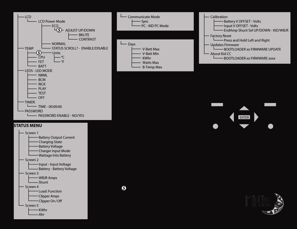
22 22 Page
23 Initial Set-Up and Use These instructions are for firmware revision New features are added frequently. Now that your KID is all wired up, Wind and Hydro generator in place, battery bank installed, Kid Clipper connected to the Kid and to the turbine it is time to turn things on. Get a digital meter. Good low cost meters are readily available so there is no excuse to not have one. You will need one if support is ever required. Check list: Make sure the Clipper brake is in the STOP position (Avoid applying the brake when the generator is at maximum RPM. NOTE: the brake switch operates by short circuiting the generator output. Verify that your generator is compatible with this type of brake. If not, an alternative means must be utilized to limit turbine RPM during installation and commissioning.). The Kid battery and input breakers should be off at this time.you didn t have them turned on while wiring, did you? Measure the battery voltage to insure you don t have a bad battery or any bad connections. Read from Battery plus to battery minus to get your nominal voltage. A 1 2V battery should read between 11.5 and By the way if it does read below 1 2V, that is not a good sign! Then measure it again at The KID terminals. It should be the same as at the battery. While taking these measurements, verify that the polarity is correct. If the battery voltage is 11 volts or above and polarity at the Kid connection is correct, it's time to turn on the Kid battery breaker. Search Mode : Turn on the battery breaker. If this is the first time it has been turned on, you will see KID Searching. If no other unit is found then The KID will skip right to the Start up menu". If another unit is found The KID will ask the user for the communication mode. The communication cable MUST be connected to the other unit and both units powered up for search mode to find other units in the system. KID Se a r c h i n g... o t h e r un i t s 05 If your battery bank is 1 2V, then hit the right arrow key to advance to the next set up selection. If you have a different battery bank voltage than what is displayed, then hit the up or down arrow key until the desired nominal battery voltage is displayed. Once the correct voltage is displayed, hit the right arrow key. Ba t t e r y No m i n a l Vo l t a g e i s 12V 23 Page
24 The next set of screens are where you select battery type. Selecting the applicable battery type sets some important parameters that are specific to different battery chemistries. Note: These are conservative settings for initial startup and are not a substitute for the actual charging parameters provided by the battery manufacturer. The first choice is Flooded. Use the up and down arrows to see all the choices listed below. Ba t t e r y Ty p e Fl o o d e d Ba t t e r y Ty p e AGM Ba t t e r y Ty p e GEL Ba t t e r y Ty p e Li t h i um Ba t t e r y Ty p e Ca l c i um Ba t t e r y Ty p e Cus t o m Stop on the correct battery type and then hit the right arrow key. It then takes you to the absorb voltage screen. 24 Page
25 Ba t t e r y Ab s o r b Vo l t s When the absorb screen appears, use the up/down arrow to adjust absorb voltage. Consult your battery manufacturer for their recommended settings. There is no such thing as one setting that fits all flooded or AGM etc. batteries. Different manufacturers have different requirements. Differences may be subtle, but The KID is capable of very fine adjustment. There is no reason to guess as to these important settings. When done, hit the right arrow key to go to the Float settings screen. Ba t t e r y Fl o a t Vo l t s Setting the Float voltage is accomplished exactly the same as the previous Absorb voltage. Use the up down arrows to adjust the float voltage according to your battery manufacturer s recommendations. When done, hit the right arrow key to bring you to the Equalize screen. Ba t t e r y Eq ua l i z e Vo l t s Default is volts. A Gel or AGM style battery may be damaged by higher voltages, Refer to the battery manufacturer's instructions. Flooded batteries require periodic Equalizing to reduce sulfation. Consult your battery manufacturer's specifications for a correct EQ setting. If your type of battery does not want to ever be EQ d, then simply set the EQ voltage to the Absorb voltage. When done, hit the right arrow key to bring you to the Input Function screen. In p ut Fun c t i o n *Wi n d USe t Hy d r o This screen is where you select what type of charge controller you will configure The KID for. Use the up /down arrow keys to select desired mode, then hit the right arrow key. The screen changes to say DATA HAS BEEN SAVED and then switches to the status screen below Re s t i n g 12. 4V Wi n d 0W 25 Page
26 STATUS BUTTON/SCREENS: The KID has several status display screens showing voltage, charge mode, temperatures, currents, and voltages. These screens are displayed any time that the LCD is on and you are not in a menu. If you press the STATUS button the following screens will be displayed. The first screen is displayed by default and the others are available by pressing the right arrow. The left arrow will step back through the status display screens. 9. 5A BULKMPPT Wi n d 257W The 9.5a as depicted above represents the battery output current. BULKMPPT shows the state that the charger is in. BULKMPPT means The KID is going all out to put all available energy into the batteries. The 1 2.7V represents battery voltage. The WIND shows it is in Wind mode. The 257W shows the instantaneous wattage going into the battery. Push the right arrow key to bring up the second status screen shown below. In p ut Ba t t e r y 59. 6V 13. 5V This second status screen is showing the input voltage and battery voltage. The input voltage corresponds to the Max power voltage from the input for the present conditions. Push the right arrow key to bring up the third status screen. 9. 5a SOC 93% 372Ah Re m a i n i n g This third status screen is showing input from the WBJr. (Sold Separately). In this display 9.5 amps are going to the batteries, State of Charge is 93% and 372 Amp hours remain in the batteries. Push the right arrow key to bring up the fourth status screen. Lo a d : Cl i p p e r 0. 0a Of f This fourth status screen is showing what mode the Clipper is in, the current that the load is drawing and whether the Clipper is on or off. Push the right arrow key to bring up the fifth status screen. KWh r 0. 0 KID Ah r 0. 0 When The KID has been idle for five minutes the display will cycle through the status and temperature screens. Each screen will display for a few seconds and then advance to the next. You may press any key anytime to stop auto scrolling. Scrolling may be disabled in the LCD Menu. This fifth status screen is showing daily power produced in Kilowatt hours and Amphours. 26 Page


27 The KID's L.E.D.s. The KID has several L.E.D.s to indicate modes and errors. RFC - Received Full Charge. The battery has received a full charge in the last week. 1 WK - One Week. It has been more than one week since a full charge. - IN AGS Mode indicates generator running. 2WK - Two Weeks. It has been more than two weeks since a full charge. FLT - Float. The battery has reached float stage. OVR - Limit. When blinking fast The KID has reached output current limit. When solid The KID has detected input or battery over voltage in the wind/hydro or the battery terminals. For more Info see HyperVOC section. ERR - Error. The KID has stopped due to an error. - In AGS mode indicates generator did not start. CLP - Clipper On/Off. LEDs 27 Page

28 MAIN MENUS: The KID has 7 MAIN MENU headings. This section deals with the MAIN MENU headings only. Each of the 7 main menus is explained in detail on the following pages. Press the MENU/BACK key. This button takes you to all of the Main Menus. Main menus are something you want to become familiar with. No matter where you are at in any menu, you can always get to the Main Menus by pressing the MENU\BACK button once or twice. You scroll through Main Menus from left to right. The left most Main Menu is as follows: Ad j us t Se t p o i n t <Ba t t e r y > Lo a d Notice the word BATTERY is in brackets. That means the BATTERY menu will be activated if the ENTER button is pushed. Battery Menu: The BATTERY menu allows you to set all battery charging parameters just like what was done in the initial set up. The BATTERY menu has additional adjustments beyond what the initial set up had. After the first time activating The KID, this is the way to change Battery charging parameters. The adjustments and settings available inside the BATTERY menu are: Absorb voltage and time settings Float voltage settings Equalize voltage and time settings Amp limits for battery charging and load draw Temperature compensation adjustability Temp comp during EQ Advanced settings - End Amps and Rebulk 28 Page
29 Manual EQ- Manual Equalize it will do a single EQ cycle on the batteries if enough power is available from the wind or hydro source. To set EQ parameters: Press Main Menu and select Battery, Go to EQ and press Enter, Press the SETUP Button to adjust the EQ Voltage and Time. To start an EQ cycle: Press Main Menu and select Battery, Go to EQ and press Enter, Select START, The EQ Cycle will begin. Eq ua l i z e : MANUAL *OFF START Battery Charge Stages and Meanings / Setup Bulk MPPT This stage of The KID means; that The KID will be putting out as much current as it can trying to charge the batteries to the absorb voltage set point. This is also known as constant current mode. Absorb This stage means that The KID will maintain the absorb set point voltage until the batteries are charged or it reaches Float stage. At this stage The KID is not putting out maximum current, as that would increase the battery voltage over the Absorb set point. This is also referred to as constant voltage mode. The battery is considered full at the end of the absorb charge cycle. The absorb time is proportional to the bulk time. (i.e. the time bulk takes to reach the absorb voltage.) The battery it s considered full at the end of the absorb charge cycle. Contact your battery manufacturer to determine the appropriate absorb time. Float The Float stage follows after the Absorb stage has been completed. At this point the batteries are considered full and The KID's incoming current is adjusted to maintain a full battery as system loads turn on and off. Equalize The intent of an equalization charge is to bring all battery cells to an equal voltage by a deliberate overcharge. The goal is to return each battery cell to its optimum condition through a series of voltage controlled chemical reactions inside the batteries. Not all batteries can be equalized. Consult the battery manufacturer for further details REV 29 Page
30 Advanced Battery Settings: Located under the Battery menu a submenu labelled Advanced. This menu contains advanced charge settings. EndAmps: Best results are obtained when a Whiz Bang Jr. (Sold Separately) is connected to The KID. End Amps refers to the amount of current flowing to the batteries. When End Amps are set, this function will act as a secondary termination to the absorb timer. The End Amps function works by monitoring the current going into the batteries during the absorb stage. As the batteries charge, the current needed to maintain the Absorb voltage set-point reduces and depending on the battery bank type and size there is a current flow level that indicates that the batteries are full. End Amps are that level, if the current flow goes below the End amps setting for one minute then the Absorb cycle will be terminated and it will go to Float stage. Shunt Selection: The shunt is used to measure End Amps (Above). Selecting between the internal shunt and the optional Whiz Bang Jr. is found in the Calibration menu. From the main menu TECH - Calibration. Rebulk: Rebulk is the Voltage set-point at which the Float stage will terminate and return to Bulk. In Float, The KID will return to Bulk if a load placed on the battery bank reduces the battery bank voltage below the Rebulk set point for two minutes. 30 Page
31 Load Menu: Fun c : Cl i p p e r *Of f Aut o The KID Clipper is connected to the LOAD terminals of the main KID terminal block. The Kid Clipper negative is connected to the Load/Clipper negative terminal. Note that this output is only to be used for input voltage regulation with the Kid Clipper and is NOT intended to control an inverter or other large load. Do Not Connect an Inverter No Matter how small to The KID's Load Output. Scrolling to the right will bring you to the LOAD menu. In the Wind version of the Kid, Clipper Control is the only mode available in the Load menu. Press the SET UP key to enter the Clipper Setup Menu. Clipper Setup Menu: SET LOAD/CLIPPER BATT<LOAD>INPUT These are the settings that make the Clipper regulate the input voltage to protect the Kid and prevent turbine over speed. Note: It is important to know the unloaded/ open circuit voltage of the turbine. If not known, start with a conservative value and work up from there to find a balance between proper operation and maximum turbine RPM. Do not exceed 1 45 volts. Batt+: this is the voltage that is maintained when the battery reaches Absorb or Float and the Kid is reducing the load on the turbine. The turbine output will be allowed to reach battery voltage plus whatever the Batt+ setting is. For example, if the battery is at Absorb at 57.0 volts and the Batt+ setting is set to 1 0 volts, then the Kid will regulate the battery voltage to 57.0 and the turbine output to 67.0 volts. This setting needs to be high enough to prevent the Clipper from clipping all the power from the turbine, but not so high as to allow turbine over speed. VpvStop: this is the voltage at which the Clipper enters full regulation mode by applying all of the turbine output to the Clipper resistors. This applies a braking force to the turbine, lowering RPM and reducing the input voltage to safe levels. This is best described as a Fail Safe mode. Using the UP/DOWN arrow keys, select the Batt+ voltage and then press Save. Scroll to the right and using the UP/DOWN arow keys, select the VpvStop voltage, then press SAVE. *Ba t t V 31 Page Vp v St o p 113V
32 Input Menu: ADJ UST MPPT MODE LOAD <INPUT> AUX The INPUT MENU is where you turn charging on and off and select charging mode. There are different selections for how The KID will track your wind or hydro system. Selections are below: Note: Mode must be manually turned ON after changing the mode. To turn the Mode ON: highlight the OFF under ON/OFF and switch it to ON. Press the Save to save this change. Press menu back when done. Modes will revert to OFF if the up or down arrows are pressed before exiting. To access the INPUT menu: Press Menu Back >>Scroll right to INPUT>>ENTER>>UP/DOWN to desired Mode>>Press SETUP>> NOTE: After making any changes, press SAVE to enter the settings into memory. Wind Track This mode requires a 1 6 step wind curve to be entered into the Wind Track Setup menu. The Kid uses this curve for holding the turbine output at the Maximum Power Point for increased efficiency and turbine rpm control. This curve is specific to the turbine output characteristics. Each step consists of two variables, the input voltage from the turbine and the wattage output to the battery. The output wattage is the variable the Kid watches, the input Voltage is the variable it adjusts. As the wattage on the Output side of the controller changes, the input voltage is adjusted to match the curve you programmed. Step 0 is always the cut in voltage of the Kid and 0 watts. Step 1 is the cut in voltage of the turbine and the expected wattage at cut in. Step 1 5 is the maximum input voltage (less than 1 49) and maximum wattage output. The steps in between connect the dots so to speak. Keep in mind that the minimum voltage of step 0 must be above the wakeup voltage of the Kid. This is 4 volts above the Absorb voltage on a 1 2 volt system and 8 volts above Absorb on a 24 or 48 volt system. It is recommended to start with an initial curve and then fine tune it over time. Keep in mind that increasing voltage and/ or decreasing wattage on the first few steps can help increase turbine RPM to improve low wind speed output. Decreasing voltage on the last step or two can decrease turbine RPM at high wind speeds. 32 Page
33 Step Number V in Set the expected voltage in from the turbine *Vi n Actual Input Voltage Note: the decimal does not show Wa t t s 0 0 Actual Watts Out to Battery From the turbine Expected Watts Out Set the expected watts out at this Vin. In the top line. Using the Left/Right arrow keys, place the * next to Vin. Using the Up/Down arrow keys, scroll to the desired voltage, shown in the lower left of the display. Using the Right arrow key, place the * next to Watts and using the Up/Down arrow keys, scroll to the desired wattage, shown in the lower right of the display. Press and hold the SETUP key, use the Up arrow key to go to step1. Enter the voltage and wattage here and all the steps up to 1 5. Then press SAVE to save the curve. Press the Menu Back button to return to the Mode menu. When ready, select ON and press SAVE to turn Wind Track mode on. U-Set Voc This is a fully manual mode based on a percentage of VOC. The KID will do a voltage sweep to find the VOC, then park at the percentage of the VOC the user has set in the menu. The KID will then hold that voltage for the user selected interval. This mode is useful for constant output voltage sources. Sweep Interval time can be set from Disabled on up to 99 minutes and Voc% is adjustable from 1 00% down to 30%. Micro Hydro *In t e r v a l Di s a b l e d VOC% 100% This mode is intended for use with micro hydro systems. When the KID first turns on after the input voltage goes above battery voltage, it will sweep from that open circuit voltage down to battery voltage, finding the maximum power point voltage (MPP Voltage) along the way. Then it will return to that newly found voltage. After the original turn-on sweep, the KID will do mini sweeps automatically or at user adjustable time intervals. Micro Hydro mode has two user adjustable sweep settings, Auto mode and Sweep Interval. Sweep Interval is the time between mini-sweeps, adjustable from 1 to 99 minutes, and sweeps around the most recent MPP Voltage. Sw e e p In t e r v a l Aut o Sw e e p 01 In t e r v a l Mi n ut e s Press Save, then press menu back when done. Modes will revert to OFF if the up or down arrows are pressed before exiting. 33 Page
34 Press the right arrow to advance to the AUX MAIN MENU. SETUP AUX FUNCTION LOAD <AUX> MISC The AUX menu is where you set up various auxiliary input and output functions such as Auto Genstart, Low Battery Disconnect and the Whizbang Jr. Battery status monitor. Note: Mode must be manually turned ON after changing the mode. To turn the Mode on highlight the OFF under ON/OFF and switch it to ON. Press the Save button to save this change. Press menu back when done. Modes will revert to OFF if the up or down arrows are pressed before exiting. FUNC: WBJR OFF/AUTO - Enable/Disable/Setup the WBJR From the Status Menu: Press Menu Back Scroll to the Right and select AUX and Press Enter Select FUNC:WBJR Press the Right arrow button to Auto. Press the Save Button Press SETUP button to set the Battery Capacity. scroll to the right to set Battery Efficiency. Scroll right to set the Battery Temp Ref. Scroll right to set the Battery Change %. Press the Save Button. Important! Do Not Exceed 1 2VDC at 1 00 ma Relay Drive. Use Normally Open (N.O.) Contacts. See page 34 for more information. FUNC: Gen Start OFF/AUTO/ON - Enable/Disable/Setup Auto Generator Starting To use Gen Start: From the Status Menu: Press Menu Back Scroll to the Right and select AUX and Press Enter Select FUNC:Gen Start Press the Right button to Auto or *ON Press the Save Button Press SETUP button to set the battery voltage threshold to start the generator. scroll to the right to set the Gen Start delay. scroll to the right to set the Gen On At Volts. Scroll right to set the Min Gen Runtime. Scroll right to set the Max Gen Runtime. Scroll right to set the Gen Run Confirm Voltage. Press the Save Button FUNC: LBD High OFF/AUTO - Enable/Disable/Setup Low Battery Disconnect High 34 From the Status Menu: Press Menu Back Scroll to the Right and select AUX and Press Enter Select FUNC:LBD High Press the Right button to Auto. Press the Save Button Press SETUP button to set the AlrmON Voltage. scroll to the right to set AlrmOFF Voltage. Press the Save Button REV Page
35 FUNC: LBD Low OFF/AUTO - Enable/Disable/Setup Low Battery Disconnect High From the Status Menu: Press Menu Back Scroll to the Right and select AUX and Press Enter Select FUNC:LBD Low Press SETUP button to set the AlrmON Voltage. scroll to the right to set AlrmOFF Voltage. Press the Save Button. Press the Right arrow button to Auto. Press the Save Button StpCharge H: When enabled and High signal is sampled in the Aux terminal the Unit will Stop Charging until the High signal is sampled Low. StpCharge L: When enabled and Low signal is sampled in the Aux terminal the Unit will Stop Charging until the Low signal is sampled High OTHER STUFF AUX <MISC> COMM Press the right arrow key to advance to the MISC menu. See page 40 for more information. The MISC menu allows adjustment for: LCD - Backlight and contrast controls can be adjusted with the up/down arrow buttons. See page 40for more information. Temp - Temperature of CPU, FET and Battery in degrees C. The temp can be changed from degrees C to degrees F using the setup button. LEDS - Sets behavior of front panel LEDs. See page 41 for more information. Timer - Shows approximate time of day. Password - Enable/Disable Password. See page 40 for more information. Press the right arrow key to advance to the COMM menu. MULTIPLE UNITS MISC <COMM> TECH The COMM menu is where sync mode is setup. Note: On earlier units Sync Mode was known as Follow Me. Sync Mode: When the master KID changes state, Absorb, Time, Float or Equalize it sends a signal downstream to the next one to follow and change state. Then the second one sends the same message downstream and so on until all units are in the new state. There is no limit to how many controllers can be connected in Sync mode. 35 Page
36 PC- KID PC Mode: Use this mode with a serial terminal program in a PC to display the following data: Displayed Battery Voltage Displayed Input Voltage Displayed Output in Watts KWHs produced Amp Hours Produced Battery Temperature Whiz Bang Jr. Current Battery state of charge Whiz Bang Jr. Amp Hours Remaining Select and save PC Comm to enable this mode. Data is sent once a minute. Data is comma separated raw decimal format and must be divided by 1 0 to display correctly. Press the right arrow key to advance to the DATA menu. Data Menu: Displays 31 days of saved data. After 31 days, stored memories are overwritten leaving the last 31 days. Recorded data includes Max Battery Voltage, Min Battery Voltage, KWH produced, Max Watts, and Max Batt Temp. Press the right arrow key to advance to the TECH menu. The TECH menu is for tech savvy individuals. ADVANCED MENU COMM <TECH> EndAmp Shunt Sel: - Selects between The KID's internal shunt and the (optional) WBJr's shunt. To adjust the settings: Press Menu Back Scroll to the right then select TECH and press Enter Select Calibrate and press Enter Press the right arrow until EndAmp Shunt Sel is on the top line of the LCD Use the Up and Down buttons to adjust to the desired setting Press the SAVE button to keep the settings. Reset to factory defaults. Setting things back to factory defaults is useful after your brother in law was observed messing with all the buttons and you can t trust what he did. So, reset and start over entering all the settings you know you want. Firmware Update. To do a firmware update on The KID you will need the following: A laptop or PC with Windows XP/7/8/8.1 /1 0 or Linux. Mac is not supported. If using Win 8 or newer use the Win 8 updater. Disable Anti Virus. A USB Mini-B cable (not included). Procedure: Go to and download the latest firmware file. Save the file to a known location on your PC (eg. Desktop \). Plug in the USB cable to The KID connector located on the bottom of the unit. Plug the other end into an available USB port on the PC. 36 Page
37 Go to MAIN Menu on The KID And scroll to the right to the TECH menu and press Enter. Press the down arrow key until Firmware Update is selected and press Enter. After 5 sec the unit will turn off and display FIRMWARE UPDATE. A new empty drive will appear in your PC, open it. Drag the downloaded file to this empty drive. The first green light should start blinking on The KID and "UPDATING...' should appear on the second line. It will take up to 2 minutes to update The KID. The unit will reboot with new updated firmware. Unplug the USB cable. If the update process does not complete, power down The KID, and wait 60 seconds. Hold the SETUP button while powering up The KID. This will put The KID into update mode. The KID is now ready to retry the firmware update. About KID CC: Shows the current BootLoader and FirmWare versions. 37 Page
 Contacts Auto Gen Start (AGS) This function will try to start the Generator and while monitoring battery voltage to assure the generator is charging.")
38 Auto Gen Start Important! Do Not Exceed 1 2VDC at 1 00 ma Relay Drive Use Normally Open (N.O.) Contacts Auto Gen Start (AGS) This function will try to start the Generator and while monitoring battery voltage to assure the generator is charging. If not, it will signal the generator to shut down to conserve fuel. Generator On at: Battery voltage level that will trigger the signal to start the generator. GenStart Delay: Delay in minutes that the battery voltage must be below the Generator On at setting,to signal the generator to start. MIN Gen Run Time: Minimum time in minutes the generator will run after Auto Gen Start. MAX Gen Run Time: Maximum time in minutes the generator will run after Auto Gen Start. Gen Run Confirm: When the battery voltage has dropped below the set point and the delay time has been satisfied The KID will begin the process of starting the generator. The first step it takes is to temporarily disable the input charging so it can monitor the battery voltage to verify the generator actually started. This is called The "qualifying time". The KID will then watch the battery voltage to verify that it has risen and confirm that the generator has started. This is called the "Gen Run Confirm Voltage". 38 Page
39 Setting up The KID for use with a Whiz Bang Jr. (Sold separately) State Of Charge: The KID, in conjunction with the Whiz-Bang JR. creates a very accurate battery State Of Charge meter within The KID. There is some set-up before using the WBJr and it will be necessary to enter values for Battery bank size in Amp-Hours, battery efficiency, Battery temperature compensation reference and percentage of change per degree C. Refer to the battery manufacturer's documentation for these values. After installing the Whiz-Bang Jr. one full charge cycle (until float is reached) is required before accurate readings may be obtained. To enable the WBJR on The KID: Press Main Menu button. Scroll to the right, Until Aux is in shown in brackets, <AUX> Press Enter. When the display shows FUNCTION: press the up or down arrow button until WBJR is selected. Press the Right button until the * is next to Auto. Press the SETUP button to setup the SOC portion. Press Save to save the changes. Entering battery bank information: Battery Capacity: This is the first screen after you press the SETUP button. Battery Capacity per battery can be obtained from your battery manufacturer's spec sheet. This setting is the total capacity of the battery bank and will largely depend on how your battery bank is designed. Use the up and down arrows to adjust the capacity of the battery bank. Press the Right arrow to go to the next set up. Battery Efficiency: Batteries are not 1 00 percent efficient and some loss does occur. This setting will improve accuracy by taking this inefficiency into account. Battery efficiency will be different between Manufacturers and will lower with age, 94% is a good starting point for most battery banks. Your battery bank will reach 1 00% charge as soon as it hits float stage. Use the up and down arrows to adjust the battery efficiency of the bank Press the Right button to go to the next set up. Press Save to save the changes. Battery Temperature Reference: This is a reference temperature used as a starting point for temperature based charging voltage adjustments. This is the temperature at which the battery manufacturer considers the temperature compensation to be zero, usually this will be 25 C, but it may vary by manufacturer and battery type. Use the up and down arrows to adjust the battery temp ref of the bank. Press the Right button to go to the next set up. Press Save to save the changes. Battery Change %: The change of battery capacitance in percentage above and below of the temperature reference, usually will be 1 %. Use the up and down buttons to adjust the battery capacity change percentage. Press the SAVE button to save the whole set up. Press the Status button and then scroll to the right to view the WBJR SOC screen. This screen will show you the Output current going straight to the batteries after the loads, also the SOC in percentage of the battery bank and also the Amp hours remaining on the batteries. 39 Page
40 Password protected settings: UL standards mandate that only qualified people be allowed to change critical settings. We have determined that people that have read and understood this much of the manual are qualified to change critical settings. Changing some of the settings available on The KID can result in hazardous conditions. If you do not fully understand these functions and features contact your dealer. Password: Settings such as Battery, input, load settings, calibration and Aux settings are password protected. When the password is entered it allows 1 0 min for the user to adjust protected settings. Entering secure mode: Press Main Menu, Select MISC and press Enter, Select Password and press Enter, Select Yes. When prompted, the Password is Press Save to save the changes. LCD Power Saving modes: There are 2 different LCD Power settings that can be chosen by the user, they function as follows: ECO: Eco mode is the default mode. This mode will turn off the Backlight after 5 min of no user input on the keypad. Turning the backlight off helps reduce the idle power of The KID by 1 /3 of a watt. This mode will also return the menus to the Main Status menu after 5 minutes has elapsed. To turn the backlight back on, simply press any key and the LCD will come back on. NRML: Normal LCD mode keeps the Backlight Setting as set by the user, so if the Backlight is set to on the Backlight will stay on. The backlight draws 1 /3 watt, so it isn t a big power drain to leave it on. Scrolling Status Screens: When The KID has no user input for 5 minutes the Screen will automatically go to the status Screen and scroll though all status screens one by one every 3 seconds or so. It was designed so it would not interfere with the user setting the unit parameters, but if this is not what you want your unit to do you can always disable this feature: - Press Menu Back and scroll to the MISC menu and press Enter - Select LCD and press Enter and Scroll to the right to select Status Scroll? - Press the down key to Disable - Scroll to the left and select the LCD Power Mode - Press Save. Backlight/Contrast: To adjust the backlight and contrast of the LCD, press the SETUP button in the LCD Power Savings 40 Page
41 Screen. Use the up and down buttons to adjust them. LED MODE: Located under the MISC menu, the LED mode can be set to several different modes, some useful and some just for fun. NRML: this mode will employ all the available LEDs as indicators, The top 3 LEDs refer to the Battery Capacity Meter function on The KID that indicates to the user the current battery status at a glance. The FLT LED will come on when the unit goes to Float. It will blink Slowly when the unit goes to Float MPPT. This mode will also use the Warning (OVR) LED to indicate when there is an anomaly on the unit, such as Over Voltage or Current Limit. The ERR LED is also active to indicate Faults on the system. The CLP LED will come on when the clipper is active and it will blink to indicate a warning on the load circuit. BCM: The BCM function on the LEDs will only employ the top 3 BCM LEDs and the OVR and ERR LEDs. RICK: this mode is also known as minimal LED usage, since it will only use the Warning and Error LEDs. PLAY: this mode is great for special occasions where you want to Show off your KID s fun side, it will trail the LEDs from top to bottom as long as this mode is selected. TEST: Useful to verify that all the LEDs are functioning. OFF: will keep the LEDs OFF, except for the ERROR LED. Absolute Maximum Ratings Max Output Current C* Max Input Short Circuit Current Amps DC Max Output source Backfeed Amps DC DC Output Voltage VDC Input Battery Voltage , 24, 36, or 48 VDC Input Battery Voltage Range VDC Operating Temperature Range C to 50 C* *Derated to C. Fuses / Overcurrent protection. Replace fuses with the same type and ratings: Type ATC 32V 30 Amps Max. The fuses provided in The KID are for supplemental protection. External overcurrent protection is required as part of the installation. Caution! Never remove or replace a fuse without turning off all power to the Kid. Failure to do so may result in burnt or pitted fuse holders. 41 Page

42 Wiring Diagrams D.C. System Important! Both the input and output negatives must be connected to their own separate terminals. Tying them together will cause inaccurate current readings and possible damage to the unit. 42 Page Important! Both the input and output negatives must be connected to their own separate terminals. Tying them together will cause inaccurate current readings and possible damage to the unit. Three Phase System


43 HyperVOC Why do you need HyperVOC? Hyper VOC is a non-operational buffer between The KID Charge Controller's maximum operating input voltage of 1 51 and the absolute maximum of When the input voltage is between 1 51 V and 1 62V, The KID is unable to charge the battery bank, but it has not been harmed by over voltage. Any voltage above 1 62V will result in severe damage to the charge controller which is not covered by warranty. Hyper VOC, coupled with a properly designed system, will protect your charge controller from being over voltaged. Above: HyperVOC voltage limits above normal operating voltage. 43 Page


44 Example of an available Pre-Wired System Pre-wired system with integrated KID charge controller. Accessories Below are optional accessories and accessory kits. MNKID-BREAKER-30A 30 Amp replacement circuit breaker for The KID. 44 Page


45 Accessories Continued MNHydrometer Easy to use battery hydrometer for checking the specific gravity on all "Flooded" style batteries. Size: 5.25"L x 4.25"W x 1.5"D MNBCM / MNBCMS : Battery Status Monitor 1. LEDs that correspond to battery voltage 2. Voltage accuracy +-.05% 3. Auto sensing for 1 2, 24, 36, and 48 volt batteries 4. LED indicators show if batteries have received a full charge recently, longer than one week or longer than two weeks 5. Ideal for "at a glance" readings - golf carts, forklifts, etc. Description: Battery Capacity Meter Size 4.5"L x 3.75"W x 1 "D Box Size 5"L x 4"W x 2"D Weight 1 Lb. 45 Page

46 Accessories Continued Whiz Bang Jr.: The Whiz Bang Jr. is designed to work with The KID to give accurate battery status. The Whiz Bang Jr. keeps track of Amp-Hours going into and out of the battery. Simple one-wire installation. 500A 50mV Shunt not included. The Whiz Bang Jr can also provide shunt access for co-operative products. 46 Page


47 Optional Circuit Breakers and Accessories Quad Big Baby The Big Baby is an aluminum powder coated breaker enclosure that holds four DINRail breakers. The Quad is an aluminum powder coated breaker enclosure that holds four panel mount breakers. 63 amp 1 50VDC din rail mount DC ground fault protector (NRTL listed breaker assy). More circuit breakers and accessories available at MNDCGFP-63 MNEPV Breaker 1 50VDC din rail mount breaker (1 3mm wide). MNEPV evaluated by ETL to 1 50VDC. 1 50VDC ETL listed in the US and Canada 1 0,000 AIC. MNEDC Breaker DC Panel mount breaker available up to 1 00 amps. MNSHUNT 500A 50mA shunt used with WBJr 47 Page
48 Warranty MIDNITE SOLAR INC. LIMITED WARRANTY MidNite Solar Power electronics, sheet metal enclosures and accessories MIDNITE SOLAR INC. LIMITED WARRANTY MidNite Solar Power electronics, sheet metal enclosures and accessories MidNite Solar Inc. warrants to the original customer that its products shall be free from defects in materials and workmanship. This warranty will be valid for a period of five (5) years for all products except the MNBRAT Charge Controller along with the MNBIRDHOUSE1 batteries, these will be two (2) years. MidNite Solar will not warranty third party inverter components used in MidNite's pre-wired systems. Those components are warranted by the original manufacturer. At its option, MidNite Solar will repair or replace at no charge any MidNite product that proves to be defective within such warranty period. This warranty shall not apply if the MidNite Solar product has been damaged by unreasonable use, accident, negligence, service or modification by anyone other than MidNite Solar, or by any other causes unrelated to materials and workmanship. The original consumer purchaser must retain original purchase receipt for proof of purchase as a condition precedent to warranty coverage. To receive in-warranty service, the defective product must be received no later than two (2) weeks after the end of the warranty period. The product must be accompanied by proof of purchase and Return Authorization (RA) number issued by MidNite Solar. For an RMA number contact MidNite Solar Inc., th Ave NE, Arlington, WA (360) Purchasers must prepay all delivery costs or shipping charges to return any defective MidNite Solar product under this warranty policy. Except for the warranty that the products are made in accordance with, the specifications therefore supplied or agreed to by customer: MIDNITE SOLAR MAKES NO WARRANTY EXPRESSED OR IMPLIED, AND ANY IMPLIED WARRANTY OF MERCHANTABILITY OR FITNESS FOR A PARTICULAR PURPOSE WHICH EXCEEDS THE FOREGOING WARRANTY IS HEREBY DISCLAIMED BY MIDNITE SOLAR AND EXCLUDED FROM ANY AGREEMENT MADE BY ACCEPTANCE OF ANY ORDER PURSUANT TO THIS QUOTATION. MIDNITE SOLAR WILL NOT BE LIABLE FOR ANY CONSEQUENTIAL DAMAGES, LOSS OR EXPENSE ARISING IN CONNECTION WITH THE USE OF OR THE INABILITY TO USE ITS GOODS FOR ANY PURPOSE WHATSOEVER. MIDNITE SOLAR S MAXIMUM LIABILITY SHALL NOT IN ANY CASE EXCEED THE CONTRACT PRICE FOR THE GOODS CLAIMED TO BE DEFECTIVE OR UNSUITABLE. Products will be considered accepted by customer unless written notice to the contrary is given to MidNite Solar within ten (1 0) days of such delivery to customer. MIDNITE SOLAR is not responsible for loss or damage to products owned by customer and located on MIDNITE SOLAR S premises caused by fire or other casualties beyond MIDNITE SOLAR s control. This warranty is in lieu of all other warranties expressed or implied. MIDNITE SOLAR INC TH AVE NE ARLINGTON, WA info@midnitesolar.com PH: FAX: Page

49 * * The MNKID-C1 D2 is rated -40 to 40 C 49 Page
50 Glossary Absorb... A charging state where the battery is held at the absorb volt setting for a time set by the user. AGS... Automatic Generator Start Amp... A measurement of electrical current. Amp-Hour... A measurement of electrical power. Amps x Hours. Aux... Auxiliary port for input or output. Used to control relays, WbJr. input etc. AWG... American Wire Gauge. BATT... Battery or Battery Bank. BTS... Battery Temp Sensor. Bulk... A charging state where all available power goes to the battery until it reaches the Absorb voltage setting. Clipper... A controlled dump load to help prevent overcharging / turbine overspeed. EMI... Electro Magnetic Interference. Electrical noise. EQ... Equalization charge. An extended charge to match charge level on battery cells. Firmware... Updatable control software. Float... A charging state to maintain a fully charged battery. GFI... Ground Fault Interrupter - Detects ground faults and opens the circuit. LED... Light Emitting Diode. LVD... Low Voltage Disconnect. OVD... Over Voltage Disconnect. MPPT... Maximum Power Point Tracking. Adjusts loading on the wind or hydro generator for optimum power yield. The KID employs MPPT. Minus... Negative battery or input connection or Negative load connection Plus... Positive power connection. PV... PhotoVoltaic. PWM... Pulse Width Modulation. How some charge controllers maintain regulation. Rebulk... The Voltage set-point at which the Float stage will terminate and return to Bulk. Sync... A way to connect multiple KIDs on different arrays to charge one battery bank. Temp Comp... An automatic adjustment to the charging voltage based on battery temperature. Three Stage Charging... A charging scheme for batteries with three levels of charging. Three Stooge Charging... Oh, a wise guy, eh? Nyuh, Nyuh, Nyuh. VOC... Volts Open Circuit. The unloaded generator output voltage. Watt... Instantaneous power. Amps x Volts = Watts. Watt-Hour... A measurement of electrical energy, Watts x Hours = Watt-Hours. WbJr... Whiz Bang Junior - An optional current sense board mounted to customer's 500A/50mV shunt. 50 Page

51 51 Page

52 Photocopies of the template may not be accurate and should be avoided. To use this template: Remove template from the manual and secure to the wall with a low tack tape such as scotch or masking tape. Other tapes are more likely to stick to the paint when they are removed. Remove all tape within 24 hours. Make sure that the template is flat and not crooked. Use a large drill inside the cut-out area to create an entry point for the saw. Use a drywall or jig saw and cut along the dotted lines using caution especially around the corners. A hole saw may be used in the inside corners. Drill the four corner holes with the smallest drill that will work with your hardware. Use caution to avoid breaking through to the large cut-out area. Put The KID in place and secure with appropriate hardware Page Wall Mounting Template
MNBE-8D2x2 INSTRUCTIONS
 MNBE-8D2x2 INSTRUCTIONS MNBE-8D2x2 OUTDOOR 3R ENCLOSURE MNBE-8D2x2 Battery Enclosure with locking door and one shelf. Outdoor 3R rain type design. Powder coated aluminum and stainless steel construction.
The Brat Solar Charge Controller Quick Start Guide. Features
 The Brat Solar Charge Controller Quick Start Guide This quick start guide is for Beta units only. Not all features of released units are available in Beta units. More details are available within this
The KID Solar Charge Controller Instruction Manual
 The KID Solar Charge Controller Instruction Manual PRODUCT FEATURES MPPT Tracking. True paralleling - Inputs and Outputs for two KIDs. Up to 1 50V input. Now available with Auto Gen-Start. MidNite's exclusive
Battery Enclosure Installation Instructions
 MNBE-C Battery Enclosure Instructions Battery Enclosure Installation Instructions MNBE-C These instructions are for the installation of Midnite Solar Battery Enclosure models MNBE-C, MNBE-CL16 and MNBE-C8D
SAVE THESE INSTRUCTIONS
 MNPV12 & 16 Combiner Instructions Applications: SAVE THESE INSTRUCTIONS PV combiner up to 16 strings using MNPV breakers rated for 150VDC. 120 amps total output PV combiner up to 12 strings using 600VDC
The Kid Solar Charge Controller Instruction Manual. Features
 The Kid Solar Charge Controller Instruction Manual Features MPPT charge controller gives maximum yield for solar Standard model can wall or flush mount Marine model includes mounting bracket Backlit LCD
MNSOB Shut Off Box Instructions
 MNSOB Shut Off Box Instructions MNSOB4X-4P MNSOB3R-4P The MNSOB Shut off boxes provide a Rapid System Shutdown as required by NEC 690.12. This Manual covers the following models: MNSOB4X-2P MNSOB4X-4P
SAVE THESE INSTRUCTIONS
 MNPV10, MNPV12 Combiner Applications: SAVE THESE INSTRUCTIONS PV combiner up to 12 strings using MNPV breakers 1000 VDC Combiner using MNTS touch safe fuse holders and fuses rated for 1000VDC DC load center
MNDC-X2 INSTRUCTIONS
 MNDC-X2 INSTRUCTIONS Models: MNDC125-X2, MNDC175-X2, MNDC250-X2 The MNDC125-X2 Based on our Narrow E-Panel chassis and MNDC175-X2 and MNDC250-X2 based on our wide E-Panel chassis with a blank door the
MNPV Installation Instructions
 14000 Burn Rd Arlington, WA 98223 USA Ph (425)374-9060 www.midnitesolar.com MNPV Installation Instructions The MNPV6 combiner is rated for outdoor use. Designed for combining PV strings up to 150VDC and
GV-10 Manual 10.5A / 140W IMPORTANT SAFETY INSTRUCTIONS SAVE THESE INSTRUCTIONS. Solar Charge Controllers with Maximum Power Point Tracking
 GV-10 Manual Solar Charge Controllers with Maximum Power Point Tracking For models: GV-10-Pb-12V: GV-10-Pb-CV: 12V Lead-Acid/AGM/Gel/Sealed/Flooded 12V Custom Multi-Stage Lead-Acid/AGM/Gel/ Sealed/Flooded
MASTERsine Inverter PXA Series Installation Guide
 Backup Power System Expert TM MASTERsine Inverter PXA Series Installation Guide Important Safety Instructions IMPORTANT: Read and save this Installation Guide for future reference. This chapter contains
Model: SE-4020-CA Automatic Battery Charger
 OWNERS MANUAL Model: SE-4020-CA Automatic Battery Charger PLEASE SAVE THIS OWNERS MANUAL AND READ BEFORE EACH USE. This manual will explain how to use the battery charger safely and effectively. Please
Magnum AC Coupled In a D3R battery box MND3RACCPLME 7/20/18
 Magnum AC Coupled In a D3R battery box MND3RACCPLME 7/20/18 SAVE THESE INSTRUCTIONS - These instructions contain important safety and operating instructions for the MidNite Solar Battery Enclosure Size
GVB-8 (Boost) Manual
 Manual") www.genasun.com GVB-8 (Boost) Manual Solar Charge Controllers with Maximum Power Point Tracking For models: GVB-8-Pb-12V: 12V Lead-Acid/AGM/Gel/Sealed/Flooded GVB-8-Pb-24V: 24V Lead-Acid/AGM/Gel/Sealed/Flooded
www.genasun.com GVB-8 (Boost) Manual Solar Charge Controllers with Maximum Power Point Tracking For models: GVB-8-Pb-12V: 12V Lead-Acid/AGM/Gel/Sealed/Flooded GVB-8-Pb-24V: 24V Lead-Acid/AGM/Gel/Sealed/Flooded
User Manual. Solar Charge Controller 3KW
 User Manual Solar Charge Controller 3KW 1 CONTENTS 1 ABOUT THIS MANUAL... 3 1.1 Purpose... 3 1.2 Scope... 3 1.3 SAFETY INSTRUCTIONS... 3 2 INTRODUCTION... 4 2.1 Features... 4 2.2 Product Overview... 5
GVB-8 (Boost) Manual
 Manual") GVB-8 (Boost) Manual Solar Charge Controllers with Maximum Power Point Tracking For models: GVB-8-Pb-12V: 12V Lead-Acid/AGM/Gel/Sealed/Flooded GVB-8-Pb-24V: GVB-8-Pb-36V: GVB-8-Pb-48V: GVB-8-Pb-CV: 24V
GVB-8 (Boost) Manual Solar Charge Controllers with Maximum Power Point Tracking For models: GVB-8-Pb-12V: 12V Lead-Acid/AGM/Gel/Sealed/Flooded GVB-8-Pb-24V: GVB-8-Pb-36V: GVB-8-Pb-48V: GVB-8-Pb-CV: 24V
MNPV2, MNPV3, MNPV4, MNPV6 Instructions
 MNPV2, MNPV3, MNPV4, MNPV6 Instructions The MNPV6 combiner is rated for outdoor use. Designed for combining PV strings up to 150VDC and 120 amps total using breakers, or high voltage strings up to 1000VDC
CLASSIC MPPT CHARGE CONTROLLERS
 CLASSIC MPPT CHARGE CONTROLLERS The worlds most sophisticated MPPT charge controller BAR NONE!!! THE CLASSICS The Classic line of MPPT charge controllers are one of the most powerful in the RE industry.
PUMP PLUS 2000 PLC MODEL #: PP AUTOMATIC DUAL OUTPUT BATTERY CHARGER INSTRUCTION MANUAL
 INSTRUCTION MANUAL PUMP PLUS 2000 PLC AUTOMATIC DUAL OUTPUT BATTERY CHARGER Supplied with Dual Bar Graph Display MODEL #: 091-237-12-PP INPUT: 120 Volt, 60 Hz, 3.5 Amps OUTPUT BATTERY 1 and 2: 15 or 18
AUTO CHARGE 11 MODEL #: XX. AUTOMATIC BATTERY CHARGER U.L. Configuration INSTRUCTION MANUAL
 INSTRUCTION MANUAL AUTO CHARGE 11 AUTOMATIC BATTERY CHARGER U.L. Configuration MODEL #: 091-11-XX NOTE : This charger is designed for vehicles with dual batteries and negative ground. CAUTION This unit
Clipper Instructions
 Clipper Instructions The MNCLIPPER works alone or with the MidNite Solar Classic MPPT Charge Controller to provide the highest level of performance and protection possible. Features: Helps protect turbine
AUTO CHARGE 12 AUTOMATIC BATTERY CHARGER
 INSTRUCTION MANUAL FILE: 091-165-12 reve Rev: E, page 8 DATE: 7-02-15 AUTO CHARGE 12 AUTOMATIC BATTERY CHARGER MODEL #091-165-12 NOTE : This charger is designed for vehicles with a single battery and negative
12V 1 AMP (1000 ma) Automatic Battery Charger & Maintainer
 Automatic Battery Charger & Maintainer") 12V 1 AMP (1000 ma) Automatic Battery Charger & Maintainer For lead-acid batteries THIS MANUAL CONTAINS IMPORTANT SAFETY AND OPERATING INSTRUCTIONS FOR 12V BATTERY CHARGER: YUA1201000 / INT1201000 KEEP
12V 1 AMP (1000 ma) Automatic Battery Charger & Maintainer For lead-acid batteries THIS MANUAL CONTAINS IMPORTANT SAFETY AND OPERATING INSTRUCTIONS FOR 12V BATTERY CHARGER: YUA1201000 / INT1201000 KEEP
User Manual Solar Charge Controller 3KW
 User Manual Solar Charge Controller 3KW Version: 1.3 CONTENTS 1 ABOUT THIS MANUAL... 1 1.1 Purpose... 1 1.2 Scope... 1 1.3 SAFETY INSTRUCTIONS... 1 2 INTRODUCTION... 2 2.1 Features... 2 2.2 Product Overview...
AUTO CHARGE 12 HO MODEL #: MODEL #: MODEL #: AUTOMATIC SINGLE OUTPUT BATTERY CHARGER INSTRUCTION MANUAL
 INSTRUCTION MANUAL AUTO CHARGE 12 HO AUTOMATIC SINGLE OUTPUT BATTERY CHARGER MODEL #: 091-170-6 MODEL #: 091-170-12 MODEL #: 091-170-24 File: IM_091-170-xx_revd.indd Rev: D Revised By: MFG Date: 10-23-2013
OPERATOR'S MANUAL IMPORTANT SAFETY INSTRUCTIONS
 ASSOCIATED OPERATOR'S MANUAL IMPORTANT SAFETY INSTRUCTIONS MODEL 6366 12 VOLT, 0-20 AMP 4 X 20 BATTERY CHARGER 1. SAVE THESE INSTRUCTIONS. This manual contains important safety and operating instructions
AUTO CHARGE DUAL MODEL #: AUTOMATIC DUAL OUTPUT BATTERY CHARGER INSTRUCTION MANUAL. Ph: Fax:
 INSTRUCTION MANUAL AUTO CHARGE DUAL AUTOMATIC DUAL OUTPUT BATTERY CHARGER MODEL #: 091-145-12 INPUT: 120 Volt, 50/60 Hz, 3.5 Amps OUTPUT BAT 1: 10 Amps OUTPUT BAT 2: 10 Amps File: IM_091-145-12_revb.indd
Safety, Installation and Operating Instructions Instructions importantes concernant la sécurité
 ! Safety, Installation and Operating Instructions Instructions importantes concernant la sécurité Manual for the following Battery Fuel Gauge models: BFGOV12V, BFGOV24V, BFGOV36V, BFGOV48V, BFGOV64V and
AUTO CHARGE 4000 MODEL #: LOW PROFILE CHARGER AUTOMATIC DUAL OUTPUT BATTERY CHARGER INSTRUCTION MANUAL
 INSTRUCTION MANUAL AUTO CHARGE 4000 LOW PROFILE CHARGER AUTOMATIC DUAL OUTPUT BATTERY CHARGER Unit supplied with this display MODEL #: 091-89-12 INPUT: 120 Volt, 50/60 Hz, 5 Amps OUTPUT: 45 Amps File:
MODEL 6010A 6 12 VOLT BATTERY CHARGER ASSOCIATE
 MODEL 600A 6 VOLT BATTERY CHARGER ASSOCIATE IMPORTANT SAFETY INSTRUCTIONS. SAVE THESE INSTRUCTIONS. This manual contains important safety and operating instructions for the battery charger you have purchased.
AC CONVERTER / BATTERY CHARGER
 AC CONVERTER / BATTERY CHARGER User s Manual MODEL #: CON120AC12/24VDC Listed to UL 458 and CSA 22.2 NO. 107.1 Standards Contents INTRODUCTION... 3 Important Safety Instructions... 3 1. General Description...
Models: SP3, SPSS3 Automatic Battery Charger
 OWNERS MANUAL Models: SP3, SPSS3 Automatic Battery Charger PLEASE SAVE THIS OWNERS MANUAL AND READ BEFORE EACH USE. This manual will explain how to use the charger safely and effectively. Please read and
LPC 20 MODEL #: LOW PROFILE CHARGER AUTOMATIC SINGLE OUTPUT BATTERY CHARGER INSTRUCTION MANUAL
 INSTRUCTION MANUAL LPC 20 LOW PROFILE CHARGER AUTOMATIC SINGLE OUTPUT BATTERY CHARGER Unit supplied with one of these displays MODEL #: 091-207-12 INPUT: 120 Volt, 50/60 Hz, 7 Amps OUTPUT: 20 Amps File:
LESTRONIC II BATTERY CHARGER MODEL 07210
 LESTRONIC II BATTERY CHARGER MODEL 07210 PLEASE SAVE THESE IMPORTANT SAFETY AND OPERATING INSTRUCTIONS For correct operation of the equipment, it is important to read and be familiar with this entire manual
SP6. Automatic Battery Charger. Model
 Model SP6 Automatic Battery Charger OWNERS MANUAL PLEASE SAVE THIS OWNERS MANUAL AND READ BEFORE EACH USE. This manual will explain how to use the charger safely and effectively. Please read and follow
Art. No. EC-315. Art. No. EC-330. Art. No. EC-340 SWITCH-MODE BATTTERY CHARGER CONTENTS IMPORTANT SAFETY PRECAUTIONS... 2
 SWITCH-MODE BATTTERY CHARGER CONTENTS IMPORTANT SAFETY PRECAUTIONS... 2 DESCRIPTION AND FEATURES... 3 CHARGING STAGES... 4 Art. No. EC-315 Art. No. EC-330 Art. No. EC-340 PROTECTIONS... 5 INSTALLATION...
OWNERS MANUAL Models: XP400, XP500, XP750C INSTANT POWER Jump Starter and DC Power Source
 OWNERS MANUAL Models: XP400, XP500, XP750C INSTANT POWER Jump Starter and DC Power Source XP400 XP500 XP750C PLEASE SAVE THIS OWNER S MANUAL AND READ BEFORE EACH USE. This manual will explain how to use
Sentry Battery Charger. Installation and Operations Manual Section 75
 Sentry Battery Charger Installation and Operations Manual 00-02-0616 03-03-08 Section 75 In order to consistently bring you the highest quality, full featured products, we reserve the right to change our
BATTERY SAVER LOW RIPPLE HO
 INSTRUCTION MANUAL BATTERY SAVER LOW RIPPLE HO LOW RIPPLE POWER SUPPLY / AUTOMATIC LOAD SWITCH FOR 12VDC VEHICLE SYSTEMS MODEL #: 091-195-12 INPUT: 120 Volt, 50/60 Hz, 4.5 Amps RMS OUTPUT: 13.2 Volts DC,
LPC 40 MODEL #: LOW PROFILE CHARGER WITH PLC AUTOMATIC SINGLE OUTPUT BATTERY CHARGER INSTRUCTION MANUAL
 INSTRUCTION MANUAL LPC 40 LOW PROFILE CHARGER WITH PLC AUTOMATIC SINGLE OUTPUT BATTERY CHARGER Unit supplied with one of these displays MODEL #: 091-200-12 INPUT: 120 Volt, 50/60 Hz, 5 Amps OUTPUT: 40
AUTO CHARGE D2 MODEL #: AUTOMATIC TRIPLE OUTPUT BATTERY CHARGER INSTRUCTION MANUAL
 INSTRUCTION MANUAL AUTO CHARGE D2 AUTOMATIC TRIPLE OUTPUT BATTERY CHARGER Designed Specifically for Vehicles with DDEC ENGINES MODEL #: 091-74-12 INPUT: 120 Volt, 60 Hz, 8 Amps OUTPUT VEHICLE BATTERY 1
PUMP PLUS 1000 PLC MODEL #: PP AUTOMATIC SINGLE OUTPUT BATTERY CHARGER INSTRUCTION MANUAL
 INSTRUCTION MANUAL PUMP PLUS 1000 PLC AUTOMATIC SINGLE OUTPUT BATTERY CHARGER Unit supplied with one of these displays MODEL #: 091-215-12-PP INPUT: 120 Volt, 60 Hz, 3.5 Amps OUTPUT BATTERY 1 and 2: 15
IMPORTANT SAFETY INSTRUCTIONS IMPORTANT: READ AND SAVE THIS SAFETY AND INSTRUCTION MANUAL. KEEP IT WITH OR NEAR CHARGER AT ALL TIMES.
 IMPORTANT SAFETY INSTRUCTIONS IMPORTANT: READ AND SAVE THIS SAFETY AND INSTRUCTION MANUAL. KEEP IT WITH OR NEAR CHARGER AT ALL TIMES. SPECIFICATIONS: For technical assistance, call your Dealer with the
AUTO CHARGE D PUMP PLUS
 INSTRUCTION MANUAL AUTO CHARGE D PUMP PLUS AUTOMATIC DUAL OUTPUT BATTERY CHARGER Designed Specifically for Vehicles with DDEC ENGINES MODEL #: 091-9-DPP INPUT: 120 Volt, 60 Hz, 8 Amps OUTPUT VEHICLE BATTERY:
MNPV6 Disco / MNPV6-250 MNPV6-AC Disco Installation Instructions
 MNPV6 Disco / MNPV6-250 MNPV6-AC Disco Installation Instructions MNPV6 Disco Shown with optional circuit breakers The MNPV6 Disco combiner is rated for outdoor use. Designed for combining PV strings up
Cruising Charger Series OWNER S MANUAL
 R Cruising Charger Series OWNER S MANUAL ON BOARD BATTERY CHARGERS Models DC Amperage No. Of Banks Volts 2614A 5,10 Amps 2 Bank 12/12 2614A-230 2621A 5,5,10 Amps 3 Banks 12/12/12 2621A-230 2622A 10,10
Installation and Operating Instructions. MPPT Solar System Controller ISC3040
 Installation and Operating Instructions MPPT Solar System Controller ISC3040 ABOUT THIS MANUAL These operating instructions come with the product and should be kept with it as a reference to all user s
INTELLIGENT BATTERY CHARGER/MAINTAINER
 INTELLIGENT BATTERY CHARGER/MAINTAINER OWNER S MANUAL Read carefully and understand all ASSEMBLY AND OPERATION INSTRUCTIONS before operating. Failure to follow the safety rules and other basic safety precautions
AUTOMATIC BEST BATTERY SELECTOR INSTALLATION & OPERATION BBS-4800 BBS-4800E
 AUTOMATIC BEST BATTERY SELECTOR INSTALLATION & OPERATION BBS-4800 BBS-4800E SENS part no: 101312 Document revision: K DCN No. 107455 Date 4/2/18 1840 Industrial Circle Longmont, CO 80501 Fax: (303) 678-7504
AUTO CHARGE 4000 MODEL #: AUTOMATIC DUAL OUTPUT BATTERY CHARGER INSTRUCTION MANUAL. Ph: Fax:
 INSTRUCTION MANUAL AUTO CHARGE 4000 AUTOMATIC DUAL OUTPUT BATTERY CHARGER MODEL #: 091-89-12 INPUT: 120 Volt, 50/60 Hz, 8 Amps OUTPUT BATTERY CHARGER: 40 Amps OUTPUT BATTERY SAVER: 5 Amps File: IM_091-89-12_reve.indd
Deltran Battery Tender 6V/12V 4Amp 5 & 10 Bank Battery Management System TABLE 1. Length of Cord, Feet AWG Size of Cord
 Deltran Battery Tender 6V/12V 4Amp 5 & 10 Bank Battery Management System Designed for Six-cell and three-cell Flooded/AGM/GEL Lead-Acid Batteries and Four-Cell Lithium Iron Phosphate (LiFePO4) Batteries
The Traveler Series TM : Adventurer
 The Traveler Series TM : Adventurer 30A PWM Flush Mount Charge Controller w/ LCD Display 2775 E. Philadelphia St., Ontario, CA 91761 1-800-330-8678 Version: 3.4 Important Safety Instructions Please save
The Traveler Series: Adventurer
 The Traveler Series: Adventurer RENOGY 30A Flush Mount Charge Controller Manual 2775 E. Philadelphia St., Ontario, CA 91761 1-800-330-8678 Version: 2.2 Important Safety Instructions Please save these instructions.
The Traveler Series: Wanderer
 The Traveler Series: Wanderer RENOGY 30A PWM Charge Controller Manual 2775 E. Philadelphia St., Ontario, CA 91761 1-800-330-8678 1 Version: 2.3 Important Safety Instructions Please save these instructions.
PSJ-2212, PSJ-3612, PSJ-4424
 Model: PSJ-2212, PSJ-3612, PSJ-4424 Jump Starter and DC Power Source OWNER S MANUAL PSJ-2212 PLEASE SAVE THIS OWNER S MANUAL AND READ BEFORE EACH USE. This manual will explain how to use your jump starter
Installation and Operating Instructions. Solar System Controller ISC3030
 Installation and Operating Instructions Solar System Controller ISC3030 ABOUT THIS MANUAL These operating instructions come with the product and should be kept with it as a reference to all user s of the
DANGER OF DEATH TO YOUR CLASSIC
 ATTENTION: Please Read this cover letter BEFORE installing the Classic-SL For help with the Classic, Classic Lite or Classic-SL please see our how to videos and extended documentation. Please visit this
Battery Power Inverters
 Battery Power Inverters Renogy 500W 1000W 2000W Pure Sine Wave Inverter Manual 2775 E. Philadelphia St., Ontario, CA 91761 1-800-330-8678 1 Version 1.4 Important Safety Instructions Please save these instructions.
The Traveler Series: Wanderer
 The Traveler Series: Wanderer RENOGY 30A Charge Controller Manual 2775 E. Philadelphia St., Ontario, CA 91761 1-800-330-8678 Version: 2.0 Important Safety Instructions Please save these instructions. This
Installation and operating instructions. Solar charge controller MPPT 10 A / 20 A Z Z
 Installation and operating instructions Solar charge controller MPPT 10 A / 20 A EN 1 Contents 1. About these instructions... 3 1.1 Applicability... 3 1.2 Users... 3 1.3 Description of symbols... 3 2.
Nature Power Inverters. True Sinewave Inverter Modified Sinewave Inverter. Owner s Manual
 Version 1.1 Version 2 Nature Power Inverters True Sinewave Inverter Modified Sinewave Inverter Owner s Manual!!!!!!!!!!! 38304 38204 For safe and optimum performance, the Power Inverter must be used properly.
Installation and Operating Instructions. Solar System Controller ISC3020
 Installation and Operating Instructions Solar System Controller ISC3020 ABOUT THIS MANUAL These operating instructions come with the product and should be kept with it as a reference to all user s of
MODEL 6017 OPERATOR'S MANUAL
 MODEL 6017 OPERATOR'S MANUAL ASSOCIATE D IMPORTANT SAFETY INSTRUCTIONS 1. SAVE THESE INSTRUCTIONS. This manual contains important safety and operating instructions for the battery charger you have purchased.
MNE-240 E-PANEL INSTRUCTIONS
 MNE-240 Series E-Panel Owner s Manual 1 P a g e 1 0-0 2 9-1 R E V : B IMPORTANT SAFETY INSTRUCTIS SAVE THESE INSTRUCTIS - These instructions contain important safety and operating instructions for MidNite
GVB-8 (Boost) Manual
 Manual") GVB-8 (Boost) Manual Solar Charge Controllers with Maximum Power Point Tracking For models: GVB-8-Pb-12V: 12V Lead-Acid/AGM/Gel/Sealed/Flooded GVB-8-Pb-24V: GVB-8-Pb-36V: GVB-8-Pb-48V: GVB-8-Pb-CV: 24V
GVB-8 (Boost) Manual Solar Charge Controllers with Maximum Power Point Tracking For models: GVB-8-Pb-12V: 12V Lead-Acid/AGM/Gel/Sealed/Flooded GVB-8-Pb-24V: GVB-8-Pb-36V: GVB-8-Pb-48V: GVB-8-Pb-CV: 24V
Palomino BATTERY CHARGERS. Installation and Operating Instructions. One Technology Place Caledonia, New York The Power of Excellence
 Palomino BATTERY CHARGERS Installation and Operating Instructions One Technology Place Caledonia, New York 14423 The Power of Excellence FM1320 REV - B IMPORTANT SAFETY INSTRUCTIONS INSTRUCTIONS IMPORTANTES
SCC-MPPT Solar Charge Controller
 Solar Charge Controller Quick Guide 200W 300W 400W 600W 850W V. 2.2 1. Introduction solar charge controller uses PWM-based DSP controller to keep the batteries regulated and prevent batteries from overcharging
5300 Series Installation Guidelines
 1-800-443-4859 5300 Series Installation Guidelines WARNING: RISK OF ELECTRICAL SHOCK OR BURNS. THIS CONVERTER ASSEMBLY SHOULD BE INSTALLED BY A QUALIFIED ELECTRICIAN OR CERTIFIED RV TECHNICIAN. IMPROPER
Duo Battery Charge Controller
 Duo Battery Charge Controller RENOGY 10A 20A Pulse Width Modulation Solar Charge Controller Manual 1 2775 E. Philadelphia St., Ontario CA 91761 1-800-330-8678 Version: 1.2 Important Safety Instructions
SCC-MPPT Solar Charge Controller
 Table 4: Alarm point for low battery voltage table Model Alarm point SCC-MPPT-300 10.5 V SCC-MPPT-600 21.0 V Table 5: Charging hour table for reference Battery Capacity To 90% capacity @ 25A charging current
24V HEAVY DUTY JUMP STARTER/ POWER BANK MB3752. Storage. Specifications
 Storage Warning! When not in use store your instruction manual and product in a safe and dry place. Before re-use after storage it is recommended that the product is checked by a suitably qualified person
PHOTOVOLTAIC SYSTEM CONTROLLERS SUNSAVER MODELS INCLUDED IN THIS MANUAL SS-6 / SS-6L SS-10 / SS-10L SS-10-24V / SS-10L-24V SS-20L SS-20L-24V
 PHOTOVOLTAIC SYSTEM CONTROLLERS OPERATOR S MANUAL SUNSAVER MODELS INCLUDED IN THIS MANUAL SS-6 / SS-6L SS-10 / SS-10L SS-10-24V / SS-10L-24V SS-20L SS-20L-24V 6A / 12V 10A / 12V 10A / 24V 20A / 12V 20A
SCC-MPPT Solar Charge Controller
 Table 3: Charging voltage for 4 types of battery Battery Battery 12V battery system 24V battery system Type Type Code Bulk Floating Bulk Floating Vented 01 14.3 V 13.2 V 28.6 V 26.4 V Sealed 02 14.3 V
Pure Sine Wave Inverter Charger
 Pure Sine Wave Inverter Charger Renogy 1000W 2000W Pure Sine Wave Inverter Charger Manual 2775 E. Philadelphia St., Ontario, CA 91761 1-800-330-8678 Version 1.6 1 Important Safety Instructions Please save
Eclipse Solar Suitcase
 Eclipse Solar Suitcase Renogy 100W 200W 2775 E. Philadelphia St., Ontario, CA 91761 1-800-330-8678 Version 1.0 Important Safety Instructions Please save these instructions. This manual contains important
installation and operating instructions for the following xtreme Battery chargers:
 installation and operating instructions for the following xtreme Battery chargers: Model Name No. of Banks Amps Per Bank Battery System Dual Pro SE Xtreme Dual Pro Xtreme Three Bank SE Xtreme Three Bank
801 BUSINESS CENTER DRIVE MOUNT PROSPECT, ILLINOIS Ext. 322
 277-999 ELECTRIC CORP. 801 BUSINESS CENTER DRIVE MOUNT PROSPECT, ILLINOIS 800-621-5485 Ext. 322 Send Warranty Product Repairs to: 605 South Vermilion, Suite C, Brownsville, TX 78521-6851 Call Customer
Whizbang Jr. Installation Instructions
 Whizbang Jr. Installation Instructions The Whizbang Junior provides highly accurate current sensing when used with compatible Midnite Solar products. However, for our customers that already own similar
PureSine 150/300 Pure Sine Wave Inverter User s Manual
 PureSine 150/300 Pure Sine Wave Inverter User s Manual 1. Important Safety Instructions WARNING! Before you install and use your Inverter, please read and follow these safety instructions. 1-1. General
CRS1, CRS2 and CRS3. For additional information please call our. PRO CHARGING SYSTEMS, LLC 1551 Heil Quaker Boulevard, LaVergne, TN
 CRS1, CRS2 and CRS3 For additional information please call our Technical Support Group 800.742.2740 PRO CHARGING SYSTEMS, LLC 1551 Heil Quaker Boulevard, LaVergne, TN 37086-3539 110310 Installation and
ACCUSENSE CHARGE SERIES ON/OFF BOARD FULLY AUTOMATIC BATTERY CHARGER
 ACCUSENSE CHARGE SERIES ON/OFF BOARD FULLY AUTOMATIC BATTERY CHARGER SPECIFICATIONS: *Photo for reference only* Part number 8890439 Mode Select: Selects Battery Type Refer to Section 6. IMPORTANT: READ
Solar Charge Controller
 Table 3: Charging voltage for 4 types of battery Battery Type Battery Type Code SC-600W MPPT Bulk Voltage Floating Voltage Vented 01 28.6 V 26.4 V Sealed 02 28.6 V 26.8 V Gel 03 28.6 V 27.4 V NiCd 04 28.6
Safety, Installation And Operating Instructions For The Following Battery Charger Models: i2412, i3612, i4809, i2425, i3625, and i4818
 Safety, Installation And Operating Instructions For The Following Battery Charger Models: i2412, i3612, i4809, i2425, i3625, and i4818 IMPORTANT NOTICE: Please save and read these safety, operating and
PI1500X Power Inverter User s Manual
 PI1500X Power Inverter User s Manual featuring WARNING Failure to follow instructions may cause damage or explosion, always shield eyes. Read entire instruction manual before use. Warning: This product
Guardian Battery Charger Series. Installation and Operations Manual Section 75
 Guardian Battery Charger Series Installation and Operations Manual 00-02-0615 02-29-08 Section 75 In order to consistently bring you the highest quality, full featured products, we reserve the right to
10 AMP ON BOARD BATTERY CHARGER
 R A Valley Forge Company MODEL 2611A-1-B 10 AMP ON BOARD BATTERY CHARGER One Output OWNER S MANUAL IMPORTANT! READ THESE INSTRUCTIONS BEFORE INSTALLING AND USING THIS PRODUCT. Keep these instructions for
Midnite Kid Basic Solar Charging Kit
 What does my kit come with? 1pc MNKID-B 30-amp MPPT Charge Controller 1pc MNBIGBABY- 4 position breaker box 2 pcs MNEPV30- PV and battery breaker 1 pc GFP63 Ground Fault Protection Breaker 2pcs each Strain
User s Manual. Automatic Switch-Mode Battery Charger
 User s Manual Automatic Switch-Mode Battery Charger IMPORTANT Read, understand, and follow these safety rules and operating instructions before using this battery charger. Only authorized and trained service
LESTRONIC II BATTERY CHARGER MODEL 19740
 *01679* LESTRONIC II BATTERY CHARGER MODEL 19740 PLEASE SAVE THESE IMPORTANT SAFETY AND OPERATING INSTRUCTIONS For correct operation of the equipment, it is important to read and be familiar with this
12V/25A BATTERY CHARGER MAINTAINER / JUMPSTARTER
 12V/25A BATTERY CHARGER MAINTAINER / JUMPSTARTER OWNER S MANUAL Read carefully and understand all ASSEMBLY AND OPERATION INSTRUCTIONS before operating. Failure to follow the safety rules and other basic
2/10/50 AMP 12 VOLT BATTERY CHARGER/ ENGINE STARTER
 2/10/50 AMP 12 VOLT BATTERY CHARGER/ ENGINE STARTER WARNING This product contains or, when used, produces a chemical known to the State of California to cause cancer and birth defects or other reproductive
MODEL 2602A-12 3 STAGE AUTOMATIC BATTERY CHARGER OWNER S MANUAL SAVE THESE INSTRUCTIONS
 R A Valley Forge Company MODEL 2602A-12 3 STAGE AUTOMATIC BATTERY CHARGER OWNER S MANUAL SAVE THESE INSTRUCTIONS 1. INTRODUCING THE CHARGER The 2602A-12 is a 3-stage electronic battery charger. Rainproof,
A48 / A48B (base plate) BATTERY CHARGER
 BATTERY CHARGER") A48 / A48B (base plate) BATTERY CHARGER CPN41054 ISSUE DATE: 12315-8/98 ECN/DATE 106 BRADROCK DRIVE DES PLAINES, IL. 60018-1967 (847) 299-1188 FAX: (847)299-3061 15349-07-07/02 16041 6/03 14575-2/01 INSTRUCTION
A48 / A48B (base plate) BATTERY CHARGER CPN41054 ISSUE DATE: 12315-8/98 ECN/DATE 106 BRADROCK DRIVE DES PLAINES, IL. 60018-1967 (847) 299-1188 FAX: (847)299-3061 15349-07-07/02 16041 6/03 14575-2/01 INSTRUCTION
SMT. Installation and Operation Manual. Model:SMT WITH MPPT TECHNOLOGY
 SMT WITH MPPT TECHNOLOGY Installation and Operation Manual Model:SMT SMT Dimensions Specification Summary System Voltage 12 V/24V Rated Battery Current 12V, 5A 8A 10A 15A 20A 25A 24V, 5A 8A 10A 15A Rated
MX60 PV MPPT Charge Controller
 MX60 PV MPPT Charge Controller QUICK & EASY GUIDE TO SETTING UP THE MX60 CHARGE CONTROLLER OutBack Power Systems, INC 19009 62nd Ave NE Arlington, WA 98223. USA Telephone: (360) 435 6030 http://www.outbackpower.com
BATTERY CHARGER CHR-1445
 BATTERY CHARGER CHR-1445 / 2685 TEL:886-4-2238-0698 FAX:886-4-2238-0891 Web Site:http://www.monicon.com.tw E-mail:sales@monicon.com.tw Copyright 2007 Monicon Instruments Co., Ltd. All right reserved. Contents
Turbo M Series onboard charger
 Turbo M Series onboard charger Operation Manual Model # Output Bank Max. Output Turbo M106 1 6 Amps Turbo M108 1 8 Amps Turbo M208 2 8 Amps Turbo M212 2 12 Amps Turbo M220 2 20 Amps Turbo M230 2 30 Amps
LESTRONIC II BATTERY CHARGER BUILT-IN OR PORTABLE CHARGERS
 LESTRONIC II BATTERY CHARGER BUILT-IN OR PORTABLE CHARGERS PLEASE SAVE THESE IMPORTANT SAFETY AND OPERATING INSTRUCTIONS For correct operation of the equipment, it is important to read and be familiar
Installation and Operating Instructions (for chargers shown below)
") Installation and Operating Instructions (for chargers shown below) For additional information please call our Technical Support Group 800.742.2740 PRO CHARGING SYSTEMS, LLC 1551 Heil Quaker Boulevard,
Installation and Operating Instructions (for chargers shown below) For additional information please call our Technical Support Group 800.742.2740 PRO CHARGING SYSTEMS, LLC 1551 Heil Quaker Boulevard,