AFT mid drive kit Trouble shooting guide For 24v to 48V Kelly Controller KBS 48101L-L 100 A peak
|
|
|
- Valentine Sims
- 5 years ago
- Views:
Transcription

1 Date: AFT mid drive kit trouble shooting guide Rev 1.7 Page 1 of 17 AFT mid drive kit Trouble shooting guide For 24v to 48V Kelly Controller KBS 48101L-L 100 Table of Contents 1. Safety Educational Requirements of service technician and Public Liability Disclaimer Tools/ Consumables required Parts for trouble shooting picture Trouble shooting Initial diagnosis questions Trouble shooting: Step 1 Bad connections Trouble shooting: Step 2 Check battery voltage at controller terminals Trouble shooting: Step 3 Check Throttle Trouble shooting: Step 4 Check For blown MOSFETS in controller Trouble shooting: Step 5 Check Hall effect Signals from motor Trouble shooting: Step 6 Short circuited motor windings Trouble shooting: Step 7 Water ingress into motor, controller or Throttle Trouble shooting: Step 8 Motor cuts out but restarts Wiring diagram Trouble shooting CHECK SHEET Fill out troubleshooting check sheet and to us... 17
2 Page 2 of Safety Carry out the work in accordance with the AFT instructions and keep hands clear from all chains and rotating assemblies at all times when in operation for your safety. Furthermore, follow all local rules and regulations whilst installing and using this kit. Take care to not short or touch cables with high voltages as you may get a shock or burns. Follow all the local regulations for working on high voltage batteries. 2. Educational Requirements of service technician and Public Liability Disclaimer With the instructions provided nearly anyone can trouble shoot or service this kit, however we recommend a qualified bicycle service technician/ mechanic or equally qualified person installs this kit. Above 200w kits are marked as Off-road use only and you take full responsibility when using this kit and also check all your local laws and regulations regarding the use of this kit. By purchasing and installing this kit you agree that AFT takes no public liability fair any loss or damages to the bicycle and/or the rider when installing or riding a bicycle with this kit. 3. Tools/ Consumables required Item no. Quantity Text 1) 1 DC Multimeter with resistance and voltage functionality 2) 2 Pins or Thin nails to insert into back of wire plugs (if needed) 3) 1 Wire cutters 4) 1 Insulation tape

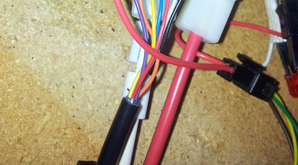
3 Page 3 of Parts for trouble shooting picture
4 Page 4 of Trouble shooting Initial diagnosis questions The first step to determining what has caused a failure in your mid drive conversion is to answer these diagnosis questions below. 1) Is the throttle switch in the ON position and is Positive power going to the Small red wire bullet connector to enable the controller? 2) Where you riding over very rough and bumpy terrain? Indication: This could indicate you have a bad connection that has come loose 3) Was it raining heavily when the motor stopped working or was it raining on the last few rides before this happened? Indication: This could indicate water has gotten into the throttle and or controller 4) Was it raining heavily when the motor went full throttle all by itself? Indication: This could indicate water has gotten into the twist throttle or cable plugs of the twist throttle. 5) Did you smell or hear a puff of smoke at the time of failure? Indication: This could indicate a blown MOSFET in the controller. 6) Did you go for a long ride, in hot weather going up steep hills at the time of failure or on your last ride event? Indication: This could indicate an overheated motor winding or faulty mosfet in the controller or possibly a failed hall sensor.


5 Page 5 of Trouble shooting: Step 1 Bad connections WARNING: When performing all these test below with live voltages be careful not to short circuit or touch any wires accidentally. Make sure to keep all metal tools and objects away from the wires since the exposed leads are live and an accidental short could easily damage the motor, controller or throttle further. BAD connections, even though it looks like things are plugged in, they maybe not connecting properly, so a good first test is to unplug ALL plugs a) Throttle 3 Pin and 2 Pin Plugs b) Battery 2 Pin Plug and single bullet connector c) 7 Pin Hall sensor Plug d) 2 Pin and 1 pin Phase wire Plugs. Look inside for internal damage or burn marks and then re-plug in all PLUGS. Look inside to make sure all PINS are protruding evenly out of the plug and that they make a good contact are not corroded. After plugging all plugs back together, test to see if the motor is now working. If not continue to the next test. 7. Trouble shooting: Step 2 Check battery voltage at controller terminals Check that battery voltage is actually getting from the battery to the controller. Setup the multi meter so the red cable plugs into V+ and that the black probe plugs into COM ground as pictured below set to voltage measure. Set the range to AUTO or 20V DC Put the 2 probes of the millimetre cables into the back of the plug that comes from the controller, as pictured in the right. Measure the voltage here, it should be ~30v to 50v Depending on what your battery pack voltage is. When you plug this cable into the battery, and there should be a spark on the contacts as the inrush current charges up the capacitors in the controller, if not their maybe a bad connection.


6 For 24v to 48V Kelly Controller KBS 48101L-L Trouble shooting: Step 3 Check Throttle The next test is for the throttle. If the throttle was locked on full throttle and this was after heavy rain, most likely their is water in the throttle or throttle plugs. If when you restart the controller and the throttle does not work, check the red error code led and if it has fault code of 2-4, then this confirms that the throttle is locked on full throttle at startup. To resolve this dry out throttle and plug joins with a hair dryer and re-test. For a permanent solution you need to place electrical tape over all exposed cable joins of thet wiring. Also if the throttle was wet inside you can also silicon the cover back onto the throttle. For other non water related throttle problems disconnect the 3 Thick Phase wires from the motor so that it does not spin when we turn the throttle later. Then make sure all other cables are plugged in and the controller powers up. Toggle the RED ON/OFF switch pictured right and make sure the controller is ON and the Red/Orange/Green Led s light up. a) Check throttle power up: When this is done, next touch the multi meter wires onto the 3 pin plug of the throttle as pictured. On one side of the plug touch the black wire from the controller and from the other side of the plug touch the red wire from the controller. You might need to push the probes in with force to get a good contact. (Opposite side of plug is so that you don t get a short between the test probes as the pins are very small and close). You should see a DC voltage of 4.8 to 5.0 V b) Check throttle speed signal If the throttle powers up ok, next you can test the throttle output signal. On one side of the plug touch the black wire from the controller and from the other side of the plug touch the white wire (middle wire) from the controller. You might need to push the probes in with force to get a good contact. (Opposite side of plug is so that you don t get a short between the test leads as the pins are very small and close). With the throttle in the closed position you should see a voltage of 0.8V, now turn the throttle and motor throttle signal voltage should rise, you should see it rise to 4.2V at full throttle. Throttle fault indication: If there is 5V supply voltage but no signal on the white wire from the controller then either the inline connector is not making contact on this white pin or the throttle is faulty and needs replacing. Page 6 of 17

 or")


7 Page 7 of Trouble shooting: Step 4 Check For blown MOSFETS in controller a) Setup Multimeter: Get your multimeter and change the range from Voltage to Continuity ( diode) or the resistance OHMS mode. Leave the probes in the same ports as before. If you have both probes sitting in free air and not touching each other you should get infinite or very HIGH resistance. One some multi meters it will show a symbol of I Infinity Or in this Mutlimeter to the right it shows up as 0.L Mega Ohms Then connect the red and black probes together and should get a reading close 0.0 Ohms

8 Page 8 of 17 b) Check continuity of power cables off the controller: You will now use the multi meter to check for continuity between ground black and between red + battery voltage. If we see a zero resistance between ground and positive, this implies that a mosfet has failed and shorted to ground. c) Check continuity of each phase off the controller: You will now use the multi meter to check for continuity between each of the 3 phase wires between ground and between + battery voltage. Hence in total there will be 6 measurements in total. Unplug the battery wires from the controller and also the 3 phase wires from the motor, and also unplug the 7 Pin Hall sensor plug. As pictured on the right, touch the multimeter probes into the back of the 2 pin power plug (polarity is not important) and also into the back of the Phase wire plugs. You may need to press firmly on the probes to get a good stable figure of resistance. Test Number Power connection cable colour Phase Connection colour Resistance (expected range) 1 Black- Gnd Blue Phase 50 to 55 K Ohms 2 Black- Gnd Yellow Phase 50 to 55 K Ohms 3 Black- Gnd Green Phase 50 to 55 K Ohms 4 Red- Positive Blue Phase 15 to 55 K Ohms 5 Red- Positive Yellow Phase 15 to 55 K Ohms 6 Red- Positive Green Phase 15 to 55 K Ohms Short circuit to ground 0 Ohms Y/N Infinite resistance You will note that when measuring the resistance it will rise over time. This is normal. If we see a zero resistance between any phase and ground or positive, this implies that this mosfet has failed and shorted. If we see significantly above 55 k ohms or Infinity resistance. Also if it makes no difference to the readings when we connect the multi meter probes, this indicates that a mosfet has failed open circuit or that there is a bad connection in the circuit we are measuring. I Y/N


9 For 24v to 48V Kelly Controller KBS 48101L-L Trouble shooting: Step 5 Check Hall effect Signals from motor If there is a fault on one or two of the hall signals, it will show up as a jumpy and not smooth operation of the motor. The motor may not spin up at all if it has stopped in certain position. In the situation that you have lost the +5V signal or the GND signal supply to the hall sensors, in this case all 3 hall signals would show a fault and the motor and controller would not turn at all. a) Prepare for hall test -Remove the primary chain from the bike motor to peddle chainwheel, and place a cloth on the motor freewheel teeth as pictured to the right. You will use this later to have a firm grip, to be able to turn the motor by turning the gearbox output shaft. -Check to see if the motor turns freely. To do this turn the motor by turning the gearbox output shaft via the freewheel. Turn it in the direction that is hard and not in the easy freewheel direction, so that you actually turn the gearbox and motor shafts. Note considerable force maybe needed to turn the gearbox backwards, if you are able to turn it then the motor it s not seized and you should continue with the next step. IMPORTANT NOTE: #1 - Sit the motor down on its back on a table, with the gearbox and freewheel at the top. -Slide back the heat shrink from the back of the motor signal plug to expose the wire terminals as pictured to the right -Disconnect the 3 thick Phase wires from the motor to the controller - Plug the 7 Pin plug into the motor from the controller - Plug the 3 pin and 2 pin plugs into the throttle -Plug the Battery into the controller Page 9 of 17


10 Page 10 of 17 Check hall sensor supply voltage Put the multi meter negative probe into the back of the 7 pin controller connecter labelled 21 black colour wire, that plugs into to the motor orange wire, pictured to the right. Put the multi meter positive probe into the back of the 7 pin motor connector on the other side so as not to get a short between probes. Connect it to pin labelled 5 from the controller, the dark yellow wire, that plugs into to the motor yellow wire, pictured to the right. You should measure a voltage of 4.78V to 5.2V DC here. If so proceed to next step. Now that we have confirmed the hall sensors are getting the correct supply voltage we can now check the individual hall sensor output signals. b) Check hall sensor A Signal Put the multi meter negative probe into the back of the 7 pin controller connecter labelled 21 black colour wire, that plugs into to the motor orange wire, pictured to the right. Put the multi meter positive probe into the back of the 7 pin controller connector. Connect it to pin labelled 18 from the controller, the light yellow wire, that plugs into to the motor black wire, pictured to the right. Take note of the voltage, and then turn the motor slowly. To do this turn the motor by turning the gearbox output shaft via the freewheel. Turn it in the direction that is hard and not in the easy freewheel direction, so that you actually turn the gearbox and motor shafts and not just the freewheel. You should measure a voltage of 66 milli Volts when not in Phase and 4.78 Volts when in Phase.


11 Page 11 of 17 c) Check hall sensor B Signal Put the multi meter negative probe into the back of the 7 pin controller connecter labelled 21 black colour wire, that plugs into to the motor orange wire, pictured to the right. Put the multi meter positive probe into the back of the 7 pin controller connector. Connect it to pin labelled 17 from the controller, the green wire, that plugs into to the motor red wire, pictured to the right. Take note of the voltage, and then turn the motor slowly. To do this turn the motor by turning the gearbox output shaft via the freewheel. Turn it in the direction that is hard and not in the easy freewheel direction, so that you actually turn the gearbox and motor shafts and not just the freewheel. You should measure a voltage of 66 milli Volts when not in Phase and 4.78 Volts when in Phase. d) Check hall sensor C Signal Put the multi meter negative probe into the back of the 7 pin controller connecter labelled 21 black colour wire, that plugs into to the motor orange wire, pictured to the right. Put the multi meter positive probe into the back of the 7 pin controller connector. Connect it to pin labelled 16 from the controller, the blue wire, that plugs into to the motor white wire, pictured to the right. Take note of the voltage, and then turn the motor slowly. To do this turn the motor by turning the gearbox output shaft via the freewheel. Turn it in the direction that is hard and not in the easy freewheel direction, so that you actually turn the gearbox and motor shafts and not just the freewheel. You should measure a voltage of 66 milli Volts when not in Phase and 4.78 Volts when in Phase. IMPORTANT NOTE: #2 - If all tests ok, go back to the step at important Note #1, otherwise if you have found a problem skip to the next section Hall section Indication - Now sit the motor down upside down with the gearboxand freewheel at the bottom, you may need to clamp the motor body in a vice, and a vice and repeat all the HALL sensor test above, this test is to test if the hall magnet ring on the motor has dislodged and hence only gives a good signal when the motor is sitting normally and not upside down.
12 Page 12 of 17 Hall sensor indication: If none of the hall sensors are working, then there is probably a break along the 5v power supply line to the hall sensors. If only one or two are not working, then it is possible that there is a break along that signal wire of this phase. Otherwise it is possible that a hall sensor was damaged from the heat in the motor or corrosion. 11. Trouble shooting: Step 6 Short circuited motor windings This is an unlikely failure mode but there is a possibility this could happen if the motor has failed after a very long high load operation, where the motor has gotten extremely hot and the insulation of the windings has stopped functioning as it should. To test this you need to measure the resistance of the winding with a low resistance motor tester. Motors that have a winding short may show considerably more drag when turning, Shorted motor windings indication: this will show in an abnormally high unloaded current draw. 12. Trouble shooting: Step 7 Water ingress into motor, controller or Throttle When water gets into the motor or controller, unusual effects can occur. To minimise the chance of this happening the motor drain hole should be facing downwards and the motor wires should be covered with silicon on entry to the motor. To minimise water entry into the controller the wire exit from the controller should be downwards, so that no water can run along the cables and into the controller. Also so that the Rs232 Plug does not get water ingress cover it, we have an optional motor controller cover that protects the Rs232 port and cable joins from water/mud splash. If water does get into the controller the effect is a stuttering motor similar to when the hall signals are not working properly. If water gets into the throttle, you may get no output or full throttle. If the controller has failed due to water ingress, it will fix itself if left to dry out or dried with a hair drier gradually. Water ingress indication: Erratic behaviour
13 Page 13 of Trouble shooting: Step 8 Motor cuts out but restarts If your motor cuts out and restarts after a short period of time then one of the protection features in either the motor, controller or battery has kicked in. To track down which one of these it could be, you need to do some test. a) If the throttle lights stay on but flash red, and the motor restarts after cooling down after waiting 10 minutes then this is a motor overheat event. If all lights on throttle go off then most likely the battery BMS has cut-out. b) Do a power cycle, i.e disconnect the battery from the controller and see if it restarts. The throttle on off switch is not a power cycle. If after power cycling the motor starts strait away without waiting 10minutes, then most likely this is not an overheat event, but more an over current or LVC event in the battery BMS or Controller fault. c) To see if it s a controller over temp/over current/lvc protection alarm, check the fault code led description on the next page.

14 Page 14 of 17


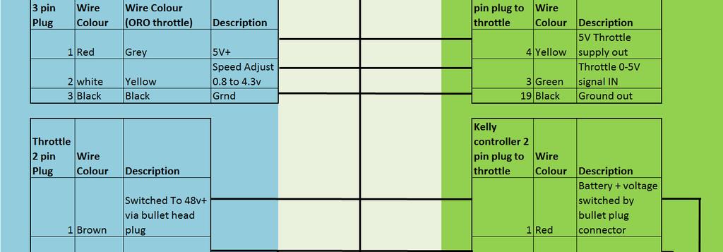

15 Page 15 of Wiring diagram
16 Page 16 of Trouble shooting CHECK SHEET Please us the results of these TEST s below : Section. Question Text 5 1 Where you riding over very rough and bumpy terrain? 2 Was it raining heavily when the motor stopped working or was it raining on the last few rides before this happened? 3 Did you smell or hear a puff of smoke at the time of failure? 4 Did you go for a long ride, in hot weather going up steep hills at the time of failure? 6 Are there any bad connections in a) b) c) or d)? 7 Is their battery voltage at the controller terminals? if so what voltage at rest? 8 A Is the throttle supply voltage present? What voltage is it? 8 B Is the throttle Output signal? What voltage does it swing from low to high? 9 Have any of the 6 continuity tests on the MOSFETS failed the tests? Which ones? 10 B Do the hall sensors receive correct supply voltage? What voltage? 10 C D E Do any of the hall sensors fail the test? Which ones? 11 Did you repeat the hall sensor test with the motor upside down? did you still get good hall signals? 12 Are there any indications of shorted motor windings? 13 Are their any indications of water ingress into the motor? Controller or throttle? Pass/ Fail Test or Yes /NO Test Results Value **SAFETY** Is Very Important:
17 Page 17 of 17 Please check that all steps have been followed and if you are unsure please contact us or your local bicycle shop to ensure the kit is installed safely onto your bicycle. For your own safety AT ALL TIMES KEEP hands and fingers away from the chains or moving parts of the bicycle when operating. 16. Fill out troubleshooting check sheet and to us Please us your trouble shooting check sheet results or if you have any further question at: For our latest upgrades and pricing please see our website:
Fit a Japanese Regulator Rectifier unit to a 12v AC/DC Royal Enfield Bullet
 Fit a Japanese Regulator Rectifier unit to a 12v AC/DC Royal Enfield Bullet The standard, seperate regulator and rectifier units on the later model Royal Enfield Bullet are not noted for their reliability.
LG Air Conditioning Universal & Multi Split Fault Codes Sheet. Universal and Multi Split Units
 Universal and Multi Split Units If there is a fault on any LG Universal or Multi unit, a two digit number will appear on the remote controllers led display. If the unit does not have a remote controller
ekit User Manual Rear Kit Cyclotricity Electric Bike Conversion Kit EBC 2018 edition
 ekit User Manual Rear Kit Cyclotricity Electric Bike Conversion Kit EBC 2018 edition 1 Contents Part 1 Before Installation - Disclaimer - Battery care - Charger - Water - Specifications - Warranty - Exceptions
Thunder Power Tarp Kit Operation. Dual Arm Curb Side Stowing Single Arm Curb Side Stowing Flex Arm Curb Side Stowing.
 Thunder Power Tarp Kit Operation Dual Arm Curb Side Stowing Single Arm Curb Side Stowing Flex Arm Curb Side Stowing 011-52475 Rev - 2 P a g e USE THE PROCEDURES BELOW TO OPERATE THE TARP SYSTEM Powering
T621 Repair Manual (Electronics)
") T621 Repair Manual (Electronics) Table of Contents 1-1-1. Product Picture-T621 1-2-1. Display-T621 1-3-1. Component Placement-T621 Display 1-3-2. Component Placement-T621 Drive Board Area 1-4-1. Block
T621 Repair Manual (Electronics) Table of Contents 1-1-1. Product Picture-T621 1-2-1. Display-T621 1-3-1. Component Placement-T621 Display 1-3-2. Component Placement-T621 Drive Board Area 1-4-1. Block
INDEX Section Page Number Remarks
 INDEX Section Page Number Remarks Synchronous Alternators 2 4 General Fault Finding Capacitors 5 6 Fault Finding & Testing Diodes,Varistors, EMC capacitors & Recifiers 7 10 Fault Finding & Testing Rotors
42 Series Step. Owner's Manual #842A. Equipped with a Permanent Magnet Motor. Table of Contents
 Owner's Manual #842A 10/05 Kwikee #1422258, Rev. 0A ED 42 Series Step Equipped with a Permanent Magnet Motor D IS C O N TI N U For steps with Control Unit 909510000 and steps without Control Units Table
Name: ACORN Inc. Address: 6450 Kingspointe Parkway, Unit 1, Orlando, Florida, IMPORTANT!
 MANUFACTURER INFORMATION: Name: ACORN Inc. Address: 6450 Kingspointe Parkway, Unit 1, Orlando, Florida, 32819 Helpline: 407 650-0216 IMPORTANT! READ THESE PROCEDURES THOROUGHLY PRIOR TO stair lift INSTALLATION
User s Manual. Automatic Switch-Mode Battery Charger
 User s Manual Automatic Switch-Mode Battery Charger IMPORTANT Read, understand, and follow these safety rules and operating instructions before using this battery charger. Only authorized and trained service
C.E. Niehoff & Co. C505, C527, C531, and C534 Alternators Troubleshooting Guide CAUTION. Testing Guidelines. Hazard Definitions WARNING
 C.E. Niehoff & Co. C505, C527, C531, and C534 Alternators Troubleshooting Guide WARNING Before troubleshooting any CEN products, the service technician should: read, understand, and agree to follow all
HOW - TO WIRING & LIGHTING
 HOW - TO WIRING & LIGHTING Tool And Material Checklist Test Light Service Manual Penetrating Oil Long-Nose Pliers T-Square or Right Angle Screwdriver Black Electrical Tape Fuses Fuse Puller Cloth or Paper
Emmo Urban. Owner s Manual
 Emmo Urban Owner s Manual 2 P a g e Table of Contents E-bike MTO Label..3 Specifications...4 Charging Your E-bike. 5-9 Brakes, Tire Pressure, and Front Carrying Case.....10 Adjusting Brakes 11 Kickstand,
Corrosion Prevention and Maintenance
 WARRANTY INFORMATION PARTS INFORMATION SERVICE INFORMATION Bulletin No. 2002-06 Circulate to: Sales Manager Accounting Service Manager Technician Parts Manager Corrosion Prevention and Maintenance Models
Troubleshooting Guide
 Troubleshooting Guide diesel - gasoline - LPG P/N 0172021 June 1999 P.O. Box 1160 St. Joseph, MO 64502-1160 1-800-255-0317 Fax: 816-360-9379 www.snorkelusa.com GENERAL INFORMATION This manual contains
1 P age. Emmo Titan. Owner s Manual. T. Lac V 1.0
 1 P age Emmo Titan Owner s Manual T. Lac V 1.0 2 P age Table of Contents E-bike MTO Label..3 Specifications...4 Charging Your E-bike. 5-6 Brakes...7 Kickstand...8 Pedals 9 Greasing Bike Chain and Rear
Emmo S6. Owner s Manual
 Emmo S6 Owner s Manual 2 P a g e Table of Contents E-bike MTO Label..3 Specifications...4 Charging Your E-bike. 5-6 Brakes...7 Kickstand...8 Pedals 9 Greasing Bike Chain and Rear Drum Brakes..... 10 Front
G203V / G213V MANUAL STEP MOTOR DRIVE
 G203V / G213V MANUAL STEP MOTOR DRIVE PRODUCT DIMENSIONS PHYSICAL AND ELECTRICAL RATINGS Minimum Maximum Units Supply Voltage 18 80 VDC Motor Current 0 7 A Power Dissipation 1 13 W Short Circuit Trip 10
SBC V In-Car Charger Dual Input (Solar MPPT & DC)
") SBC-5926 12V In-Car Charger Dual Input (Solar MPPT & DC) Operation manual Keep this manual in a safe place for quick reference at all times. This manual contains important safety and operation instructions
SBC-5926 12V In-Car Charger Dual Input (Solar MPPT & DC) Operation manual Keep this manual in a safe place for quick reference at all times. This manual contains important safety and operation instructions
Service Manual. For the SCV2832E, SCV2426, Automatic Scrubbers For: Training Troubleshooting
 Service Manual For the SCV2832E, SCV2426, SCV280000 & ES2832 Automatic Scrubbers For: Training Troubleshooting Adjustments Contents 1 Cautions ----------------------------------------------------------------------
The function of this Dynamic Active Probe has divided into three preferences on the screen main Menus:
 1.0 Introduction: This probe is designed to provide an additional help to automotive technicians in trouble shooting of electrical circuits problems in the car. Apart from using the normal multi tester,
Hub Kit Fitting Guide 2016
 Hub Kit Fitting Guide 2016 Important: For your own safety you must read this manual before attempting to fit any part of the motor kit to your bike. You must also ensure that you fit the kit in strict
SWX02 48V (REAR) Hub Kit Fitting Guide
 Hub Kit Fitting Guide") SWX02 48V (REAR) Hub Kit Fitting Guide Important: For your own safety you must read this manual before attempting to fit any part of the motor kit to your bike. You must also ensure that you fit the kit
SWX02 48V (REAR) Hub Kit Fitting Guide Important: For your own safety you must read this manual before attempting to fit any part of the motor kit to your bike. You must also ensure that you fit the kit
VC-4820 Programmable DC-DC Converter with Battery Charger function USER'S MANUAL
 1. INTRODUCTION VC-4820 Programmable DC-DC Converter with Battery Charger function USER'S MANUAL This MCU controlled Step Down DC-DC Converter has a digitally adjustable output in 0.2V increments. This
Service Bulletin. (This bulletin and all other active bulletins are downloadable from our website at
 Bulletin 00--ABDE Service Bulletin (This bulletin and all other active bulletins are downloadable from our website at www.frymaster.com/parts_service.) Bulletin 00--ABDE Page of + Worksheets Date: 0//00
HYDRA 120 & HYDRA 240 OPERATION MANUAL
 HYDRA 120 & HYDRA 240 OPERATION MANUAL The battery connector must be added to the power side of the controller (black capacitors, receiver connector, and red and black wire side). The red wire is the positive
T611 Repair Manual (Electronics)
") T611 Repair Manual (Electronics) Table of Contents 1-1-1. Product Picture T611 1-2-1. Overlay T611 1-3-1. Component Placement T611 Display Board 1-3-2. Component Placement T611 Lower Compartment 1-4-1.
T611 Repair Manual (Electronics) Table of Contents 1-1-1. Product Picture T611 1-2-1. Overlay T611 1-3-1. Component Placement T611 Display Board 1-3-2. Component Placement T611 Lower Compartment 1-4-1.
Troubleshooting Guide
 Troubleshooting Guide P/N 0153180 July 1999 P.O. Box 1160 St. Joseph, MO 64502-1160 1-800-255-0317 Fax: 816-360-9379 www.snorkelusa.com GENERAL INFORMATION This manual contains procedures for locating
1 P a g e. Emmo Knight GTS. Owner s Manual. T. Lac V 1.0
 1 P a g e Emmo Knight GTS Owner s Manual T. Lac V 1.0 2 P a g e Table of Contents E-bike MTO Label..3 Specifications...4 Charging Your E-bike. 5-6 Brakes...7 Kickstand...8 Pedals 9 Greasing Bike Chain
Customer Name: Serial Number: Y-Axis Stall
 Technician Name: Date: Technician Name: Date: Customer Name: Serial Number: Y-Axis Stall Issue Explanation and Background Each drive motor on the machine (the x, y and z axes motors) has a sensor called
NEXTUP TERMINAL STRIP CONTROLLER INSTALLATION MANUAL - VER 1.5
 CONTENTS INTRODUCTION 1 STEP ONE QUICKSHIFTER Power and Ground 3 STEP TWO QUICKSHIFTER Wiring and Final Connections 4 STEP ONE AIR SHIFTER Power and Ground 6 STEP TWO AIR SHIFTER Wiring and Final Connections
1 P age. Emmo Prestige. Owner s Manual. T. Lac V 1.0
 1 P age Emmo Prestige Owner s Manual T. Lac V 1.0 2 P age Table of Contents E-bike MTO Label..3 Specifications...4 Charging Your E-bike. 5-6 Brakes...7 Kickstand...8 Pedals 9 Greasing Bike Chain and Rear
Troubleshooting Guide
 Troubleshooting Guide diesel - gasoline - LPG diesel - gasoline - LPG diesel - gasoline - LPG P/N 0191681 May, 1999 An ISO 9001 Registered Company P.O. Box 1160 St. Joseph, MO 64502-1160 1-800-255-0317
WARNING. This product uses High Brightness LEDs. Direct viewing of the SMD LEDs at close range should be avoided. Keep product away from children.
 WARNING Before use please remove the LED Tape from its bag and allow the odour to dissipate in an unused room or outdoor building. Wash Hands after handling. This product uses High Brightness LEDs. Direct
Service Manual. Extractor Model XR28QP. For The. For: Troubleshooting Adjustments
 Service Manual For The X Ride 28 Rider Extractor Model XR28QP For: Training Troubleshooting Adjustments Contents 1 Cautions ------------------------------------------------------------------------------
1 P a g e. Emmo GT80. Owner s Manual. T. Lac V 1.0
 1 P a g e Emmo GT80 Owner s Manual T. Lac V 1.0 2 P a g e Table of Contents E-bike MTO Label..3 Specifications...4 Charging Your E-bike. 5-6 Brakes...7 Kickstand...8 Pedals 9 Greasing Bike Chain and Rear
Operating Manual OBD Link Connector
 Operating Manual OBD Link Connector OBD Link Connector (OLC) provides the following functions when it is plugged into the car or truck Diagnostic Link Connector (DLC) port: 1. TEST OBD2 PORT BEFORE PLUG
Battery Tester. GxT Incorporated, Cheboygan MI, U.S.A. All Rights Reserved E040-01G. 40 & 42HD Operator s Manual
 Battery Tester GxT Incorporated, Cheboygan MI, U.S.A. All Rights Reserved E040-01G 40 & 42HD Operator s Manual SPECIFICATIONS Measurement Range...Ferret 40... Ferret 42HD Battery Volts... 4.0 to 19.99...
User Manual of Bagibike Electric Bicycles
 User Manual of Bagibike Electric Bicycles Model: Bagibike B16. http://www.bagibike.com Page 1 FOREWORD The following operation manual is a guide to assist you. This manual is not a complete document on
Model RP310 Owner's Manual & Installation Instructions
 INSTALLATION AND INSTRUCTION MANUAL REMOTE STROBE PACK Model RP310 Owner's Manual & Installation Instructions PLITSTR223 REV. B 3/3/11 Table of Contents SAFETY WARNINGS 1 MOUNTING 2 WIRING INSTRUCTIONS
2T MY and X Trainer MY oil injection and Electrical trouble shooting guide
 2T MY 2016-18 and X Trainer MY 2015-18 oil injection and Electrical trouble shooting guide General information 1. Before performing the following diagnostic procedures, check wiring plugs and terminals
Advanced Troubleshooting Guide Snorkel V Battery Charger Rev 0 3JAN07
 Advanced Troubleshooting Guide Snorkel 3050097 24V Battery Charger Rev 0 3JAN07 1. How It Works: The 3050097 charger converts AC voltage to DC voltage, then uses high frequency to re-convert it to DC voltage/current
G213V STEP MOTOR DRIVE REV 7: March 25, 2011
 Thank you for purchasing the G213V drive. The G213V is part of Geckodrive s new generation of CPLD-based microstep drives. It has short-circuit protection for the motor outputs, over-voltage and under-voltage
ACCUSENSE CHARGE SERIES ON/OFF BOARD FULLY AUTOMATIC BATTERY CHARGER
 ACCUSENSE CHARGE SERIES ON/OFF BOARD FULLY AUTOMATIC BATTERY CHARGER SPECIFICATIONS: *Photo for reference only* Part number 8890439 Mode Select: Selects Battery Type Refer to Section 6. IMPORTANT: READ
C.E. Niehoff & Co. C703/C703A and C706 Alternators Troubleshooting Guide CAUTION. Testing Guidelines. Hazard Definitions WARNING.
 C.E. Niehoff & Co. C703/C703A and C706 Alternators Troubleshooting Guide WARNING Before troubleshooting any CEN products, the service technician should: read, understand, and agree to follow all information
Woosh GSM CD Kit Fitting Guide
 Woosh GSM CD Kit Fitting Guide Important: For your own safety you must read this manual before attempting to fit any part of the motor kit to your bike. You must also ensure that you fit the kit in strict
QuiQ Charger Troubleshooting Guide
 P O W E R I N M O T I O N Delta-Q Technologies Corp. Unit 3, 5250 Grimmer Street www.delta-q.com T 604.327.8244 Burnaby, BC Canada V5H 2H2 info@delta-q.com F 604.327.8246 QuiQ Charger Troubleshooting Guide
SELECT DIAGNOSTIC GUIDE. INST028 Doc 3.02
 SELECT DIAGNOSTIC GUIDE INST028 Doc 3.02 CONTENTS General Information...2 Select Call-Outs...3 Wire Diagram and Legend...4 Diagnostics...6 Excessive Voltage Drop Diagnostics...6 Static Diagnostics...7
Trouble Shooting Instructions
 Customer: Date: Trouble Shooting Instructions Electroair Acquisition Corp. 317 Catrell Dr., Suite #2 Howell, MI 48843 USA Ph: 517-552 552-9390 Fax: 517-552 552-9391 Email: sales@electroair.net Electroair
C.E. Niehoff & Co. C840D Alternator Troubleshooting Guide CAUTION. Testing Guidelines. Hazard Definitions WARNING.
 C.E. Niehoff & Co. C840D Alternator Troubleshooting Guide WARNING Before troubleshooting any CEN products, the service technician should: read, understand, and agree to follow all information contained
Thunder Power Tarp Kit Operation
 Thunder Power Tarp Kit Operation Dual Arm Curb Side Stowing Single Arm Curb Side Stowing 011-52476 Rev. H P a g e 2 In this booklet you will find: OPERATING INSTRUCTIONS... 3 Powering up or down the system...
1 P age. Emmo Soho. Owner s Manual. T. Lac V 1.0
 1 P age Emmo Soho Owner s Manual T. Lac V 1.0 2 P age Table of Contents E-bike MTO Label..3 Specifications...4 Charging Your E-bike. 5-6 Brakes...7 Kickstand...8 Pedals 9 Greasing Bike Chain and Rear Drum
OWNER S MANUAL Soco TS1200R Soco TS800R
 OWNER S MANUAL Soco TS1200R Soco TS800R Congratulations on purchasing your Soco electric motorcycle. We wish you an enjoyable and safe riding experience. For your safety and comfort, we recommend that
OWNER S MANUAL Soco TS1200R Soco TS800R
 OWNER S MANUAL Soco TS1200R Soco TS800R Version 1.0 May 2017 Congratulations on purchasing your Soco electric motorcycle. We wish you an enjoyable and safe riding experience. For your safety and comfort,
Mid-Drive Electric Bicycle Kit EVBIKE-SET-CMS-36 EVBIKE-SET-CMS-48 EVBIKE-SET-CMS-68 EVBIKE-SET-CMS-100
 INSTALLATION MANUAL Mid-Drive Electric Bicycle Kit EVBIKE-SET-CMS-36 EVBIKE-SET-CMS-48 EVBIKE-SET-CMS-68 EVBIKE-SET-CMS-100 Thank you for purchasing EVBIKE product and we hope that you will become a happy
4.2 Component Identification
 Digital Control Panels Deep Sea Electronics 5220 4.1 General 4.2 Component Identification 4.3 The YML5220 Controller 4.4 Description of Controls 4.5 Navigation 4.5.1 General Navigation 4.5.2 The Event
INSTRUCTION MANUAL. Maserati Alfieri Ride-On SKY SKY4735. Ver. 1
 INSTRUCTION MANUAL Maserati Alfieri Ride-On Ver. 1 SKY4734 + SKY4735 Charge item 8 to 12 hours before initial use. After initial charge, follow the normal recommended charging time. bestchoiceproducts.com
This advice was put together by Roger Butterfield for SJSC in June 2003 following the installation of a Walzendynamo 9501.
 This advice was put together by Roger Butterfield for SJSC in June 2003 following the installation of a Walzendynamo 9501. It consists of: advice about the selection of a dynamo advice on fitting the Walzendynamo
Hub Kit Fitting Guide 36V/HL
 Hub Kit Fitting Guide 36V/HL Important: For your own safety you must read this manual before attempting to fit any part of the motor kit to your bike. You must also ensure that you fit the kit in strict
VAGABOND S HANDBOOK TRANSMISSION
 03/24/07 TRANSMISSION Transmission won t engage into Gear This is caused usually by too low a Voltage to get into the ECM. This unit requires a minimum of 9VDC in order to operate at all. Almost all erratic
Pure Sine Wave Inverter GP-HS1500. Owner s Manual
 Pure Sine Wave Inverter GP-HS1500 Owner s Manual 2 Table of Contents Introduction 3 Specifications 4 Name and Main Function 5 Installation 7 Operation 9 Operating Limits 13 Troubleshooting 13 Maintenance
Using your Digital Multimeter
 Using your Digital Multimeter The multimeter is a precision instrument and must be used correctly. The rotary switch should not be turned unnecessarily. To measure Volts, Milliamps or resistance, the black
1 P a g e. Emmo Urban 2.0. Owner s Manual. T. Lac V 1.0
 1 P a g e Emmo Urban 2.0 Owner s Manual T. Lac V 1.0 2 P a g e Table of Contents E-bike MTO Label..3 Specifications...4 Charging Your E-bike. 5-9 Brakes...10 Back Drum Brakes and Tires.... 11 Pedals, Center
Series 1000 and Figure NOTE: The top terminals are showing normally closed at rest and the middle terminals are normally
 38.18.The red wire on the OCR plug carries battery voltage. Behavior: D.C. battery voltage should show-up on a volt meter when the red probe is touched to this terminal and the black probe is grounded,
MODEL No s: PP3, PP3K
 instructions for: Power PROBE 3 12-24v MODEL No s: PP3, PP3K Thank you for purchasing a Sealey product. Manufactured to a high standard this product will, if used according to these instructions and properly
SERVICE MANUAL. Kysor Instrumentation Troubleshooting Guide
 Kysor Instrumentation Troubleshooting Guide Troubleshooting Emergency One Commercial System The Medallion II instrumentation system is a Microprocessor based system utilizing both Sensor and Data bus information
LG Air conditioning CAC and Multi Split unit Fault code sheet Universal and Multi Split Units
 Universal and Multi Split Units If there is fault on any LG universal or multi unit a two digit number will appear on the remote controllers led display. If the unit does not have a remote controller the
Marine Exhaust Temperature Alarm. COMPONENTS
 Marine Exhaust Temperature Alarm. Model: SM0012 INTRODUCTION COMPONENTS Marine water cooled exhaust systems are designed to withstand temperatures of up to about 120 C. However the exhaust gases from the
Could be a damaged Rain Tracker interface module. See Bypassing the Rain Tracker on the next page.
 Rain Tracker RT-50A Troubleshooting Procedure Motor Switching Applications This procedure is for Rain Tracker installations that apply current directly to the wiper motor. For example, HSS (Hot Side Switching)
OWNERS MANUAL. Charging Batteries Up-right type - Li-ion
 OWNERS MANUAL Charging Batteries Up-right type - Li-ion To charge the battery, follow these steps: Step 1 Unlock the battery by using the key & take the battery out of the bike. Step 2 Connect the charger
PACE 500 OWNER S MANUAL
 PACE 500 OWNER S MANUAL AVENTON PACE 500 OWNER S MANUAL Thank you for purchasing an Aventon Pace 500 E-Bike! Before riding, please take a moment to review these instructions. Need service or support? Visit
oubleshooting Guide diesel - gasoline - LPG electric P.O. Box 1160 St. Joseph, MO Fax:
 Troub oubleshooting Guide diesel - gasoline - LPG electric P/N 0162737 October 2005 P.O. Box 1160 St. Joseph, MO 64502-1160 1-800-255-0317 Fax: 785-989-3075 www.snorkelusa.com GENERAL INFORMATION This
Electrically Assisted Pedal Cycles. Assembly Instructions
 Electrically Assisted Pedal Cycles Assembly Instructions Version 1 December 2005 Introduction Thank you for buying a PowaCycle Edinburgh electric bike. We hope it brings you many hours of enjoyment. For
KENSUN HID AUTOMOTIVE HEAD LAMP CONVERSION KIT INSTALLATION MANUAL
 1 KENSUN HID AUTOMOTIVE HEAD LAMP CONVERSION KIT INSTALLATION MANUAL 2 CONTENTS A. Before Installing B. Installing the Bulbs C. Installing the Ballasts D. For Bi Xenon Only: Installing the Relay Harness
JEEVES. JEEVES Installation Manual. Installation Manual The Easiest Do-It-Yourself Dumbwaiter on the Market
 1 888-323-8755 www.nwlifts.com JEEVES Installation Manual The Easiest Do-It-Yourself Dumbwaiter on the Market This manual will cover the installation procedure step-by-step. The installation of this dumbwaiter
OBAE, OBAEXU, ON BOARD Battery Chargers
 C O R P O R A T IO N O P E R A T I N G I N S T R U C T I O N S OBAE, OBAEXU, ON BOARD Battery Chargers INTRODUCTION: The OBAE line of chargers are designed for the permanent installation on battery powered
SUPER CAPACITOR CHARGE CONTROLLER KIT
 TEACHING RESOURCES ABOUT THE CIRCUIT COMPONENT FACTSHEETS HOW TO SOLDER GUIDE POWER YOUR PROJECT WITH THIS SUPER CAPACITOR CHARGE CONTROLLER KIT Version 2.0 Teaching Resources Index of Sheets TEACHING
Mobility Scooters. Owners Manual
 Mobility Scooters Owners Manual 1 Electromagnetic Interference ( EMI ) It is very important that you read this manual before using the scooter for the first time including the following information regarding
Service Manual Gulf Stream Electronic Full Wall Slide Systems
 Service Manual Gulf Stream Electronic Full Wall Slide Systems CONTENTS Page Before you operate the slide system 2 Operating Instructions 3 Preventive maintenance 3 Manually overriding your slide system
Kwikee # Series Step OWNER'S MANUAL ( )
") Kwikee #842 42 Series Step OWNER'S MANUAL (1422258) TABLE OF CONTENTS Safety Information 2 Product Information 3 Step with Control Unit 3 Operation 3 General Service 4 Prior To Operation 4 Adjusting Cam
Kwikee #842 42 Series Step OWNER'S MANUAL (1422258) TABLE OF CONTENTS Safety Information 2 Product Information 3 Step with Control Unit 3 Operation 3 General Service 4 Prior To Operation 4 Adjusting Cam
POWER ASSISTED BICYCLES OWNERS MANUAL
 OWNERS MANUAL Simply explained this is how your e.life bike basically works. Firstly may we congratulate you on purchasing your new electric power assisted e.bike. Please take time to read your manual.
PowerLevel s e r i e s
 Owner s Manual Hydraulic Leveling CONTENTS Introduction Operation Control Panel Automatic Leveling Manual Leveling Retracting Jacks Remote Operation Care & Maintenance Troubleshooting Error Codes 1 2 2
TECHNICAL NOTE #4 Revised May 24, BOGART ENGINEERING Two Bar Road, Boulder Creek, CA (831)
") TECHNICAL NOTE #4 Revised May 24, 2004 BOGART ENGINEERING 19020 Two Bar Road, Boulder Creek, CA 95006 (831) 338-0616 TROUBLESHOOTING the TriMetric battery monitor Revised for the TM-2020 TriMetric What
TECHNICAL NOTE #4 Revised May 24, 2004 BOGART ENGINEERING 19020 Two Bar Road, Boulder Creek, CA 95006 (831) 338-0616 TROUBLESHOOTING the TriMetric battery monitor Revised for the TM-2020 TriMetric What
Kelly KDC Series/PM Motor Controller User s Manual
 Kelly KDC Series/PM Motor Controller User s Manual KDC48600 KDC48601 KDC48602 KDC48603 KDC72600 KDC72601 KDC72602 KDC72603 KDC72800 KDC72801 KDC72802 KDC72803 KDC12602 KDC12603 Rev.3.3 May 2011 Contents
PHASE CONVERTERS OPERATING & MAINTENANCE INSTRUCTIONS. MODEL NO: PC40 and PC60. PART Nos:
 PHASE CONVERTERS MODEL NO: PC40 and PC60 MODEL PART No: NO: 6012805 PC20 and PC40 6012810 PC60 PART Nos: 6012800 6012805 6012810 OPERATING & MAINTENANCE INSTRUCTIONS 0107 Specifications PC20 PC40 PC60
TR22F Repair Manual (Electronics)
") TR22F Repair Manual (Electronics) Table of Contents 1-1-1. Product Picture - TR22F 1-2-1. Overlay - TR22F 1-3-1. Component Placement - TR22F Display Board 1-3-2. Component Placement - TR22F Lower Compartment
TR22F Repair Manual (Electronics) Table of Contents 1-1-1. Product Picture - TR22F 1-2-1. Overlay - TR22F 1-3-1. Component Placement - TR22F Display Board 1-3-2. Component Placement - TR22F Lower Compartment
Error codes on your Winther Cargo e-bike
 TROUBLESHOOTING Error codes on your Winther Cargo e-bike Pro-Movec A/S Brunbjergvej 2 DK-8240 Risskov Tel. +45 7027 2623 Fax. +45 7027 2429 info@promovec.dk Table of contents Introduction Identify your
Electronic Dynamo Regulator INSTRUCTION MANUAL. COPYRIGHT 2014 CLOVER SYSTEMS All Rights Reserved
 DRM TM DRM-HP TM Electronic Dynamo Regulator INSTRUCTION MANUAL COPYRIGHT 2014 CLOVER SYSTEMS All Rights Reserved INTRODUCTION The Clover Systems DRM is a state-of-the art all-electronic voltage and current
AIR BRAKES THIS SECTION IS FOR DRIVERS WHO DRIVE VEHICLES WITH AIR BRAKES
 Section 5 AIR BRAKES THIS SECTION IS FOR DRIVERS WHO DRIVE VEHICLES WITH AIR BRAKES AIR BRAKES/Section 5 SECTION 5: AIR BRAKES THIS SECTION COVERS Air Brake System Parts Dual Air Brake Systems Inspecting
Sinewave Inverters. SWING 150VA and 300VA. User s manual
 Sinewave Inverters SWING 150VA and 300VA User s manual 1 Warranty RIPEnergy is not manufacturer of these units. All technical information s, data s and dimension s rely on information s given by the manufacturer.
1 P a g e. Emmo Steel. Owner s Manual. T. Lac V 1.0
 1 P a g e Emmo Steel Owner s Manual T. Lac V 1.0 2 P a g e Table of Contents E-bike MTO Label..3 Specifications...4 Charging Your E-bike. 5-6 Brakes...7 Kickstand...8 Pedals 9 Greasing Bike Chain and Rear
READ AND FOLLOW ALL SAFETY INSTRUCTIONS SAVE THESE INSTRUCTIONS
 7.5 Swift Lock Ready Shape Tree (Patent Pending) Instructions IMPORTANT SAFETY INSTRUCTIONS When using electrical products, basic precautions should always be followed including the following: READ AND
READ BEFORE STARTING PLEASE INSTALLATION! User Manual
 PLEASE READ BEFORE STARTING INSTALLATION! User Manual Contents 1 Scope of delivery3 2 Overview of the RaceChip 4 3 Installation 5 4 Fine tuning 14 5 Trouble Shooting 16 6 Contact 20 Overview and explanation
AUTOMATIC SPRINKLER TIMER
 AUTOMATIC SPRINKLER TIMER Owner s Manual PRT-4 / PRT-6 For use with standard 24 VAC automatic sprinkler valves. These timers are designed for use in any 110 VAC /60 Hz ±10% AC outlet (240 VAC, 50 HZ for
Mash Tun / RIMS Tube Controller
 Mash Tun / RIMS Tube Controller 1 Your new mash tun / RIMS Tube controller Thanks for buying your controller from us!!! Your controller is based on the MYPIN TA4 series PID controller. Unlike cheap REX
PHOENIX Features of the Phoenix-25 : 2.3 Connecting the Motor. 2.4 Reversing Rotation. 2.5 Connecting the Receiver
 Warning! High power motor systems can be very dangerous! High currents can heat wires and batteries, causing fires and burning skin. Follow the wiring directions carefully! Model aircraft equipped with
Kelly HSR Series Motor Controller with Regen User s Manual V 3.3. Kelly HSR Opto-Isolated Series Motor Controller with Regen.
 Kelly HSR Opto-Isolated Series Motor Controller with Regen User s Manual HSR72601 HSR72801 HSR12401 HSR12601 HSR12901 HSR14301 HSR14501 HSR14701 Rev.3.3 Dec. 2011 Contents Chapter 1 Introduction... 2 1.1
INSPECTOR LINE LOAD SIMULATOR INSTRUCTION MANUAL TASCO, INC.
 INSPECTOR LINE LOAD SIMULATOR INSTRUCTION MANUAL INS120P TASCO, INC. THIS TESTER IS DESIGNED FOR USE ONLY BY QUALIFIED ELECTRICIANS. IMPORTANT SAFETY WARNINGS mwarning Read and understand this material
Main Harness Quantity: 1
 Smart Engine Start INSTALLATION MANUAL Genuine Part # : H001SVA900 Vehicle Model : WRX Kit Contents Service P/N: H001SVA910 Service P/N: H001SVA820 NOT USED NOT USED SES ECU Quantity: 1 Double-sided tape
Ignition Installation Troubleshooting Tips/Frequently-Asked Questions
 Ignition Installation Troubleshooting Tips/Frequently-Asked Questions Warning: Reversing the red and black ignition wires will destroy the ignition module and void the warranty. The Hot-Spark module s
PHOENIX Features of the Phoenix-10 : 2.3 Connecting the Motor. 2.4 Reversing Rotation. 2.5 Connecting the Receiver
 Warning! High power motor systems can be very dangerous! High currents can heat wires and batteries, causing fires and burning skin. Follow the wiring directions carefully! Model aircraft equipped with