T621 Repair Manual (Electronics)
|
|
|
- Horatio Douglas
- 5 years ago
- Views:
Transcription
1 T621 Repair Manual (Electronics)
2 Table of Contents Product Picture-T Display-T Component Placement-T621 Display Component Placement-T621 Drive Board Area Block Diagram-T Connections-T621 Display Board Connections-T621 Bridge Board Connections-T621 Drive Board Indicator LEDs-T621 Display Board Indicator LEDs-T621 Drive Board Display Specifications-T Electronics Troubleshooting Chart-T Troubleshooting-Safety Key Malfunction-T Troubleshooting-Unit Will Not Start Operating-T Troubleshooting-Key Malfunction(Display)-T Troubleshooting-Key Malfunction-T Troubleshooting-Telemetry Heart Rate Malfunction-T Troubleshooting-Contact (HTR) Heart Rate Malfunction-T Troubleshooting-The Fuse Breaks at Start-T Troubleshooting-The Fuse Breaks at Motor Start-T Troubleshooting-The Fuse Breaks during Use-T Troubleshooting-ERR-1 T Troubleshooting-ERR-3 T Troubleshooting-ERR-7 T Troubleshooting- SERVICE REQUIRED -T Other Information-Unit Settings and Information-T Other Information-SERVICE NEEDED -T621
3 Other Information-Error Messages-T Inspecting and Testing-Transformer Test T Inspecting and Testing-Motor Carbon brush T Inspecting and Testing-wheel, speed sensor T Inspecting and Testing-Motor voltage T Inspecting and Testing-Motor Thermal Sensor Test-T Inspecting and Testing-Incline Zero Switch Test-T Inspecting and Testing-Incline Motor Voltage Test -T621

4 1-1. Product Picture-T
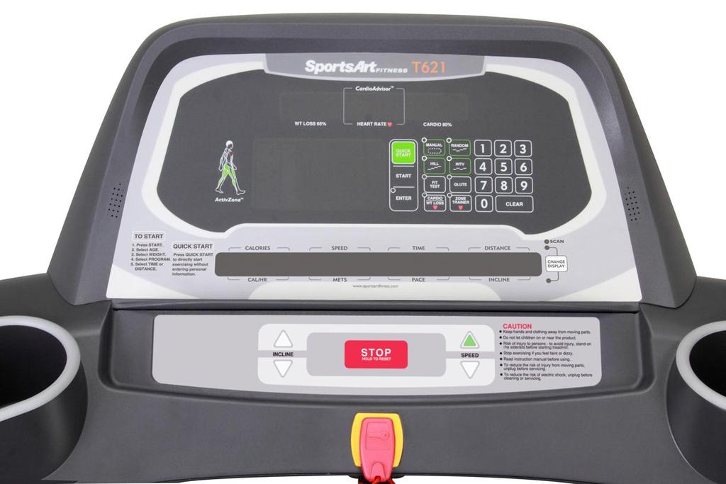
5 1-2. Display-T

6 1-3. Component Placement-T621 Display Telemetry heart rate receiver board Display board 1-3-1

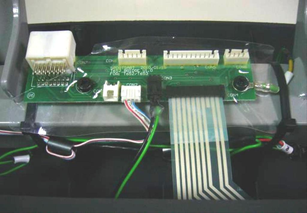
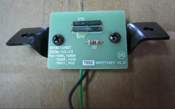
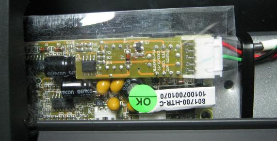
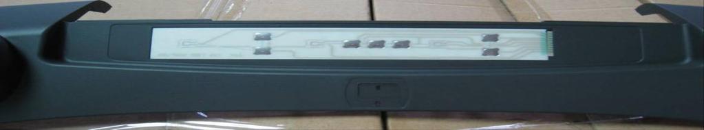
7 1-3. Component Placement-T621 Display HTR board Bridge board Safety key board Soft keys 1-3-2

8 1-3. Component Placement T621 Drive Board Area Drive board Speed sensor Temperature sensor DC motor AC incline motor Transformer Filter 1-3-3
9 1-4. Block Diagram-T621 Polar board Display board Sensor L Sensor R Safety key Keypad HTR board Bridge board AC1 AC2 FUSE SW Transformer Filter Drive board Motor Speed sensor Temperature sensor Incline motor Zero switch 1-4-1
10 1-5. Connections-T621 Display Board To telemetry HR To bridge board (HTR) To drive board To bridge board (safety key) To bridge board (fan) To bridge board (keypad) To drive board To bridge board 1-5-1
11 1-5. Connections-T621 Bridge Board To display To HTR board To safety key board 1-5-2

12 1-5. Connections-T621 Drive Board To incline motor To filter To display To speed sensor To motor To motor temperature sensor To incline zero switch 1-5-3

13 1-6. Indicator LEDs-T621 Display Board Power indicator Lit indicates display has power. HR indicator 1-6-1
. Incline fuse LED9 UP Indicator Lit = Incline is operating up.")
14 1-6. Indicator LEDs-T621 Drive Board LED4 CUS_UP Indicator Lit = Cushion motor is extended (firm). LED11 I_SENSE Indicator Lit = High current protective function is activated. Transformer fuse LED7 DN Indicator Lit = Incline is operating down. LED3 CUS_DN Indicator Lit = Cushion motor is retracted (soft). Incline fuse LED9 UP Indicator Lit = Incline is operating up. LED5 EMG Indicator Lit = There is voltage to the motor. Not lit = Emergency stop switch is activated. LED10 Motor Thermal Switch Indicator Lit = Motor is overheated; protective function is activated. LED1 SOFT Indicator Lights automatically two seconds after powering up. LED2 POWER Indicator Lit = Power is supplied. LED8 ZERO Indicator Lit = incline is already calibrated. LED6 MC Indicator Flashing indicates motor movement
15 1-7. Display Specifications-T621 Specification Details Notes Exterior power supply Motor Speed sensor 110V / 220V DC motor (with internal thermal switch) Has brushes Has heat protection Infrared optic sensor Speed Range Incline Range Display Workout Programs KPH: (KPH) MPH: (MPH) Power: AC motor (110V or 220V) Incline range: 0 % -15 % 0% setting, time control 1% per 2 seconds LED+16-segment+7-segment LED+dot matrix MANUAL, RANDOM, HILL, INTV, GLUTE, Heart rate control program Heart rate CARDIO, WT LOSS, ZONE TRAINER HTR / Telemetry 1-7-1
16 2-1. Electronics Troubleshooting Chart-T621 Malfunction Circumstance Inspection and test points Components to Safety key malfunction No start up No start up Telemetry heart rate malfunction Contact heart rate malfunction Put safety key in place. Display has no reaction. Safety key appears on the display. Power on, indicator does not light. Power on, indicator lights but the display does not light. Telemetry heart rate malfunction Contact heart rate malfunction 1. Inspect the cable connections on the lower part of the display and safety key. 2. Inspect the safety key magnet. 3. Inspect the safety key board. 1. Inspect the power cord connection. 2. Inspect all cable connections. 3. Inspect the fuse, the fuse holder, and the power switch. 4. Drive board components have an electrical short. Replace the drive board. 1. Inspect all cable connections, including connector cables. 2. Inspect whether drive board LED2 lights: a. If LED2 lights, inspect and test the transformer fuse. 3. Inspect whether LED1 on the display lights. a. If LED1 does not light, inspect the data cable from the display to the drive board. b. If LED1 does light, inspect the display program IC. Re-install the display IC. 1. Inspect the heart rate transmitter strap and its batteries. Replace batteries if they have not been replaced recently. 2. Inspect the receiver board cables. 3. Test or replace the receiver board. 4. Inspect for environmental interference, for example, from speakers and lights. 1. Inspect the HTR wire connections on the bridge board. 2. Inspect the HTR indicator light. 3. Replace the HTR board. replace Safety key board 1. Fuse, fuse holder 2. Drive board 1. Transformer 2. Drive board 3. Display board program IC 1. Heart rate transmitter 2. Heart rate receiver board 1. HTR board (HTR=heart touch rate = contact heart rate) Notes 2-1-1
17 Soft key malfunction (display) Soft key malfunction ERR 1 Press soft key, display no rebound, 1. Replace the display soft key. Soft key (display) Key does not operate, 1. Inspect the bridge board soft key connection. or operates continually. 2. Replace the soft key. Motor does not rotate, ERR1 1. There is no power to the motor; the motor appears. cannot operate. 2. Inspect the motor brushes. 3. Measure voltage from the drive board to the motor. If there is no voltage, replace the drive board. If there is voltage, inspect the following: a. transformer voltage b. whether the EMG indicator lights c. whether IGBTs have an electrical short. If so, replace the drive board. 4. Inspect the motor brushes and the commutator. ERR 1 Motor rotate, ERR1 appears, 1. The program did not detect the optic sensor signal. 2. Inspect the CLK indicator on the drive board. If the CLK indicator is not lit, clean or replace the speed sensor. If the CLK indicator lights normally, inspect the data cable from the display to the drive board. Re-install the display program IC. Re-install the display IC. ERR 3 Display speed differs from actual speed. 1. Inspect the KPH/MPH setting. 2. Inspect teeth on the optic wheel. 3. Replace the speed sensor. 4. Replace the drive board. ERR 7 ERR7 appears at startup. 1. Inspect the incline cable connections. 2. Inspect whether incline has calibrated. Soft key 1. Drive board 2. Motor brushes, commutator Speed sensor 1. Speed sensor 2. Drive board 1. Zero calibration switch 2. Drive board 2-1-2
18 KPH/MPH setting 1. Press the <CHANGE> key three seconds; the display will show UNIT-MPH or UNIT-KPH. 2. Press INCLINE< >/< > to select KPH or MPH. Press <ENTER> to confirm your choice. FOR ACCURATE HR, HOLD SENSORS FIRMLY WHILE WALKING SERVICE REQUIRED TREADMILL SHUTTING DOWN STOPPING SERVICE NEEDED-APPLY LUBE View total distance, total time FOR ACCURATE HR, HOLD SENSORS FIRMLY WHILE WALKING Display shows SERVICE REQUIRED TREADMILL SHUTTING DOWN STOPPING SERVICE NEEDED-APPLY LUBE 1. Hold contact heart rate grips firmly to test the HTR function. 2. If you are already holding grips firmly, inspect the HTR contact wire connections. 1. Motor thermal protection unit is activated. Let the unit rest half an hour or more to cool. 2. If this message often appears, please inspect the treadmill walk belt and deck. Lubricate if necessary. 3. If the walk belt is worn, replace the walk belt. 1. This lubrication prompt appears every 4000 KM. Follow lubrication and maintenance procedures in the owner s manual. 2. Enter lubrication procedure INCLINE < > + INCLINE< >+<0>. 1. Press and hold the INCLINE < > + INCLINE< > + <STOP> keys for 2 seconds. 2. The display will show the total distance and total time 2-1-3


 With safety")
19 Troubleshooting Malfunction: Safety key malfunction Circumstance: Put the safety key in place. The display does not operate. Display shows safety key. Possible cause: Safety key board malfunction Troubleshooting: 1. Inspect the safety key magnet. 2. Inspect the bridge board cable connections. 3. Test or replace the safety key board. Display board Safety key connection Bridge board Safety key & safety key board Bridge board Safety key board Reed switch Safety key(reed switch test) With safety key Reed switch ON Without safety key Reed switch OFF 3-1-1
20 Troubleshooting Malfunction: Unit does not operate Circumstance: Turn on unit power; the power indicator does not light. Possible cause: Inadequate incoming power supply or component malfunction. Troubleshooting: 1. Inspect the power cable connection. 2. Inspect cable connections under the motor cover. 3. Inspect the main fuse, fuse holder, and the power switch. 4. Inspect drive board components for signs of burning. Or replace the drive board as a test. Display board Drive board AC1 FUSE SW Filter Drive board Fuse, fuse holder, switch AC


21 Troubleshooting Malfunction: No start up. Unit does not operate. Circumstance of malfunction: Turn unit power on; the power indicator LED does not light. Possible causes: 1. Transformer problem. 2. Cables are not connected properly, or the drive board is malfunctioning. Troubleshooting: 1. Inspect all cable connections. 2. Inspect whether LED2 on the drive board lights. A. If LED2 does not light, inspect the transformer fuse and measure transformer input and output voltage. 3. Inspect whether LED1 on the display board lights. A. If it does not light, inspect cable connections from the display to the drive board. B. If it does light, inspect the display IC. Re-install the display IC. Transformer voltage Program IC Power led LED2 power indicator Lit indicates unit is sending 5 VDC power supply to the display. Transformer voltage(ac) AC1 LED Display board (red-red) (blue-blue) 110V (red) 220V(blue) black-black 12.5V white-white 12.5V orange-orange 29V yellow-yellow 11.5V Filter AC2 Transformer FUSE Drive board LED Transformer fuse 3-2-2


22 Troubleshooting Malfunction: Key malfunction display Circumstance of malfunction: Press display keys; The display shows no reaction. Or keys operate continually. Possible cause: 1. Wires to the display board are not connected properly. 2. Soft keys are bad. Troubleshooting: 1. Inspect soft key connections. 2. Replace the soft keys. Soft key connection Soft key Display board Keypad 3-3-1


23 Troubleshooting Malfunction: Key malfunction soft key Circumstance: Press the display key; the display shows no reaction, or keys operate continually. Possible cause: 1. Soft key malfunction 2. The bridge board soft key connections are not connected properly. Troubleshooting: 1. Inspect soft key wire connections. 2. Replace the soft keys. Display board Bridge board Bridge board Soft key connector Soft key 3-3-2


24 Troubleshooting Malfunction: No heart rate reading appears. Circumstance: No heart rate reading appears. Possible causes: 1. Heart rate transmitter battery power is insufficient. 2. Heart rate receiver is bad. 3. Environmental noise, such as lights or speakers, interferes with reception. Troubleshooting: 1. Replace transmitter or its batteries. 2. Inspect the telemetry heart rate receiver. 3. Replace the telemetry heart rate receiver. Heart rate board cable connector Display board Telemetry heart rate receiver board Red LED is heart rate signal indicator. Heart rate transmitter (battery location) Heart rate receiver board Transmitter 3-4-1


25 Troubleshooting Malfunction: Contact (Heart Touch Rate) malfunction Circumstance: Place hands on heart rate contact sensors. Heart rate values appear to be inaccurate. Possible causes: 1.HTR cable connection 2. HTR board malfunction 3. Display cable connections Troubleshooting: 1. Inspect the display cable connections. 2. Inspect bridge board HTR cable connections. 3. Inspect contact heart rate cable connections. 4. Inspect the HTR board indicator LEDs. 5. Replace the HTR board. HTR Indicators LED Name Function LED1 POLAR LED Flashing indicates incoming telemetry signal. LED2 HTR contact LED Lit indicates user is gripping HTR contact. LED3 HTR signal LED Flashing indicates incoming HTR signal. LED4 HR output Each flash indicates a pulse signal HTR connector output. Display board Bridge board HTR board HTR HTR HTR contact plate (clean here) HTR cable Sensor-R Sensor-L 3-5-1
26 Troubleshooting Malfunction: The fuse breaks. Circumstance: Turn on unit. The fuse immediately blows. Possible cause: 1. Components and the frame have an abnormal electrical short. 2. Drive board component malfunction. Troubleshooting: 1. Inspect the power cord. Is the cord insulation broken and creating an electrical short? 2. Replace the drive board as a test. (Drive board malfunctions are the most common source of blown fuses.) 3. Replace the EMI filter. Drive board AC1 FUSE SW Filter Drive board AC
27 Troubleshooting Malfunction: The fuse has broken. Circumstance: 1. Press the speed up key. The motor rotates. Then the fuse blows. Possible cause: 1. Motor windings have an electrical short. 2. Drive board malfunction. Troubleshooting: 1. Replace the drive board as a test. 2. Replace the motor as a test. 3. Replace the speed sensor as a test. Drive board Sensor Motor Display board Drive board Sensor Motor 3-6-2

28 Troubleshooting Malfunction: The fuse has blown. Circumstance: After a period of use, the fuse suddenly breaks. Possible cause: 1. Fuse holder malfunction 2. Deck or belt wear 3. Drive board malfunction Troubleshooting: 1. Inspect the fuse and fuse holder installation. 2. Inspect the mechanics: A. Is the walk belt worn or requiring lubrication? B. Inspect walk belt tightness. Is it too loose? 3. Replace the drive board as a test. 4. Inspect the motor brushes. Display board Drive board Sensor Motor motor 3-6-3
29 Troubleshooting Malfunction: Error 1 Circumstance: Press the speed key. Speed engages. Before the motor rotates, Error 1 appears. Possible cause: 1. Motor does not rotate. Drive board or motor malfunctions. Troubleshooting: 1. Inspect all cable connections. 2. Inspect the display board IC connection. 3. Measure motor voltage from the drive board. Is there voltage across M+,M-? If not, replace the drive board. If so, (A) inspect transformer output voltage. (B) inspect whether the EMG LED lights. (C) inspect whether IGBTs have an electrical short? 4. Inspect motor brushes and the commutator. Measure M+,M- voltage Display board Transformer Drive board Measure transformer voltage motor Inspect motor brushes. Motor Sensor 3-7-1
30 Troubleshooting Malfunction: ERR1 Circumstance: Press the speed up key. Motor rotates. ERR1 appears. Possible cause: 1. Motor rotates optic sensor malfunctions Troubleshooting: 1. Inspect all cable connections. 2. Inspect whether the LED6 indicator on drive board flashes. If not, the optic sensor is malfunctioning. Either clean the optic sensor sensor head or replace the optic sensor. 3. If the LED6 indicator lights, inspect the cable connections and main IC connections. Display board Optic sensor LED6 MC indicator Drive board motor Motor Sensor 3-7-2
31 Troubleshooting Malfunction: ERR3 Circumstance: Display speed and actual speed differ. Possible cause: 1. Optic wheel teeth or optic sensor malfunction 2. Drive board malfunction Troubleshooting: 1. Inspect whether optic wheel teeth are missing. 2. Replace the optic sensor as a test. 3. Replace the drive board. Display board Drive board LED6 MC Sensor Motor Inspect the optic sensor and optic sensor wheel teeth

32 Troubleshooting Malfunction: ERR7 Circumstance: The incline never recalibrated; ERR7 appeared. Possible cause: 1. Incline does not operate up or down and calibrate. 2. Drive board is malfunctioning. Troubleshooting: 1. Inspect whether incline UP or DN LEDs light during operation. 2. Drive board voltage follows: Drive board Incline motor voltage LED9 UP lit White-Black 110V or 220V LED7 DOWN lit White-Black 110V or 220V 3. When the incline is at the 0% position, does it touch the zero switch? Does LED8 light? Incline up/down LED Display board Drive board Incline Zero Incline connector motor switch Incline fuse LED8 zero switch

33 Troubleshooting Malfunction: The message SERVICE REQUIRED TREADMILL SHUTTING DOWN STOPPING appears. Possible cause: 1. The excessive heat protective function is activated. Troubleshooting: 1. This message indicates that the motor is overheating. Please turn off the unit and allow it to rest for one hour. 2. Inspect whether the motor thermal sensor is normal. 3. If the message appears often, the walk belt might require lubrication or be worn out. Lubricate or replace the walk belt as needed. 4. If these measures aren t effective, replace the walk deck or motor. Temperature sensor wire connector Temperature sensor Tem Display board Drive board Temp sensor Motor
34 Other Instructions Item: Set KPH/MPH units and view total distance and time. Method: 1. Press and hold the <CHANGE> key for three seconds to enter the user setting mode. 2. The display will show UNIT-MPH (imperial) or UNIT-KPH (metric) units. Press the INCLINE< > or < > key to toggle between MPH and KPH settings. Then press the <ENTER> key to confirm your choice. 3. The display shows DIST XXXXXX KM or DIST XXXXXX MILE. Press the <ENTER> key to proceed and view total time. 4. The display shows TIME XXXXXX HOUR. Press the <ENTER> key to proceed to view more information. 5. Software version numbers for display board and drive boards appear, one after another. After each bit of information appears, press the <ENTER> key to proceed. After the drive board software version appears, pressing the <ENTER> key brings you to the startup banner screen. Item: Clear total distance and time. Method: 1. Press the INCLINE < > + INCLINE < > + <STOP> key. The following prompt appears: PRESS INCLINE UP / DN TO SELECT CLEAR TOTAL TIME AND DISTANCE YES / NO PRESS ENTER 2. Select YES by pressing INCLINE < > / < > keys. Then press the <ENTER> key. 3. Total distance and time will be eliminated
35 Other Instructions Malfunction: SERVICE NEEDED-APPLY LUBE Circumstance: The message SERVICE NEEDED-APPLY LUBE appears, and the unit stops operating. At 4000 km of use, the lubrication service prompt SERVICE NEEDED-APPLY LUBE appears. Troubleshooting: 1. Insert the lube applicator tube as shown. 2. Simultaneously press and hold <0>+INCLINE< >+INCLINE< > for two seconds to activate the lubrication mode. The display counts down (3, 2, 1). The speed window shows 2.0 KPH (or 1.3 MPH), and the walk belt starts rotating. 3. Squeeze the bottle of lubricant into the applicator tube. Let the unit operate slowly for ten minutes. Allow the lubricant to disperse onto the walk belt. 4. After ten minutes, press the <STOP> key and remove the lube applicator tube. The display program will clear the lube distance memory. A new lubrication distance will begin to accrue. 5. After lubricating the walk belt, operate the treadmill for ten minutes to let the lubricant disperse
36 Other Instructions Item: Error messages E-1 : Display board main program has not received the optic sensor signal. E-3 : Display setting and actual speed differ. E-7 : Incline motor calibration point abnormality


 12.")
37 Inspecting and Testing Inspection point: Transformer voltage Inspection method: 1. Inspect whether the transformer fuse has blown. 2. Measure transformer voltage. 3. Set the multi-meter to the AC setting. Place probes as follows: Transformer cables Voltage red-red or blue-blue (input voltage) 110V (red)/ 220V(blue) black-black (normal power) 12.5V white-white (normal voltage) 12.5V orange-orange (incline voltage) 29V yellow-yellow (normal voltage) 11.5V Transformer connector Transformer fuse 4-1-1


38 Inspecting and Testing Inspection point: Motor brushes Inspection method: 1. Inspect motor brushes. A. Inspect brush length. If brushes are shorter than 0.7mm, replace the brushes. B. Inspect the brush surface. It should be smooth. If there are grooves, the commutator might be faulty. C. Inspect whether brush copper wires have changed color. If so, replace the brushes. Motor brushes Brush length should exceed 0.7 mm. This image shows brushes that are too short. Motor brushes If copper wires have changed color, connections are bad. Replace the brushes. Brush ends shown here have scratches, a sign of irregular wear. Replace brushes like these


39 Inspecting and Testing Inspection point: Optic wheel, optic sensor Inspection method: 1. Inspect the optic wheel placement. The optic wheel should rotate in the center of the optic sensor. It should not touch the optic sensor. 2. Inspect whether the teeth on the optic wheel have broken. 3. Pull the walk belt to allow the optic wheel to move. Inspect whether LED7 on the drive board flashes. When a tooth of the optic wheel is in the center of the optic sensor, LED7 on the drive board does not light. When a tooth of the optic wheel is not in the center of the optic sensor, LED7 on the drive board lights. 4. The optic sensor includes an infrared transmitter and a receiver. Inspect whether the optic sensor is dirty. If so, wipe it clean. LED6 optic sensor signal indicator Make sure that the optic sensor wheel rotates in the center to the optic sensor

40 Inspecting and Testing Inspection point: Motor voltage test at the drive board Inspection method: 1. Select the VDC setting on the multi-meter. Place probes on M+M- connectors on the drive board. 2. Press the SPEED< > key. The motor should operate, allowing you to measure motor voltage. Speed Drive board voltage Motor specifications Highest speed VDC 110V Lowest speed VDC 220V Place probes on M+M- connectors 4-4-1


41 Inspecting and Testing Inspection point: Motor thermal sensor test Inspection method: 1. Inspect whether the temperature sensor wire is connected properly. 2. When the motor is not too hot, remove the temperature sensor wire. Drive board LED10 will light. The display will show SERVICE REQUIRED Connect the temperature sensor wire. LED10 on the drive board will not light. 3. When the motor is too hot, LED10 will light and the treadmill will stop operating. Please stop the unit and wait one hour before use. If the same issue occurs again, lubricate the walk belt and deck. Temperature sensor wire connection Temperature sensor indicator LED 4-5-1


42 Inspecting and Testing Name: Incline zero point switch inspection Method: 1.Turn on power. At 0% incline, the zero switch is touched by the worm gear; The zero switch is on. LED8 lights. At 1%-15%, the zero switch is not touched by the worm gear; The zero switch is off. LED8 does not light. Zero switch Incline 0% 1-15% Tube Touches switch Does not touch switch Zero switch on off Picture Zero switch Incline 0% 1-15% Worm gear Touches zero switch. Does not touch zero switch. Picture Drive board Led 8 light Led 8 no light Led 8 indicator (Zero switch) Led8 zero switch 4-6-1


43 Inspecting and Testing Name: Incline motor voltage test Method: 1. Set the voltmeter to the 300 VAC or higher voltage setting. 2. Press INCLINE< >/< > keys. Incline indicator LEDs on the drive board light. 3. Measure voltage output to the incline motor. Normal readings are shown below. Display Drive board Incline motor cables Incline operates Press < > key Led9 UP lights white-black upward 110V or 220V Press < > key Led7 DOWN lights white-red 110V or 220V downward Display LED9 incline-up Indicator LED7 incline-down Indicator Drive board Black Red Incline motor Incline motor connector LED9 UP LED7 down White Incline fuse 4-7-1
T611 Repair Manual (Electronics)
") T611 Repair Manual (Electronics) Table of Contents 1-1-1. Product Picture T611 1-2-1. Overlay T611 1-3-1. Component Placement T611 Display Board 1-3-2. Component Placement T611 Lower Compartment 1-4-1.
T611 Repair Manual (Electronics) Table of Contents 1-1-1. Product Picture T611 1-2-1. Overlay T611 1-3-1. Component Placement T611 Display Board 1-3-2. Component Placement T611 Lower Compartment 1-4-1.
TR22F Repair Manual (Electronics)
") TR22F Repair Manual (Electronics) Table of Contents 1-1-1. Product Picture - TR22F 1-2-1. Overlay - TR22F 1-3-1. Component Placement - TR22F Display Board 1-3-2. Component Placement - TR22F Lower Compartment
TR22F Repair Manual (Electronics) Table of Contents 1-1-1. Product Picture - TR22F 1-2-1. Overlay - TR22F 1-3-1. Component Placement - TR22F Display Board 1-3-2. Component Placement - TR22F Lower Compartment
T631 Repair Manual (Electronics)
") T631 Repair Manual (Electronics) Table of Contents 1-1-1. Product Picture-T631 1-2-1. Display-T631 1-3-1. Component Placement-T631 Display 1-3-2. Component Placement-T631 Drive Board Area 1-4-1. Block
T631 Repair Manual (Electronics) Table of Contents 1-1-1. Product Picture-T631 1-2-1. Display-T631 1-3-1. Component Placement-T631 Display 1-3-2. Component Placement-T631 Drive Board Area 1-4-1. Block
T652 Repair Manual (Electronics)
") T652 Repair Manual (Electronics) Table of Contents 1-1-1. Product Illustration T652 1-2-1. Display T652 1-3-1. Component Placement T652 Display 1-3-2. Component Placement T652 Drive Compartment 1-4-1.
T652 Repair Manual (Electronics) Table of Contents 1-1-1. Product Illustration T652 1-2-1. Display T652 1-3-1. Component Placement T652 Display 1-3-2. Component Placement T652 Drive Compartment 1-4-1.
C520U/C531U Repair Manual
 C520U/C531U Repair Manual Table of Contents 1-1-1. Display Picture C520/C531 1-2-1. Component Placement - C520U/C531U Display 1-2-2. Component Placement - C520U/C531U Lower Body 1-3-1. Block Diagram -
T630 Treadmill Repair Manual SPORTS ART INDUSTRIAL CO., LTD.
 T630 Treadmill Repair Manual SPORTS ART INDUSTRIAL CO., LTD. Table of Contents 1. Unit Components 1-1-1. T630 Product Picture 1-1-2. T630 Treadmill Components (1) Display Area 1-1-3. T630 Treadmill Components
WARNING: ALWAYS UNPLUG THE TREADMILL FROM THE ELECTRICAL OUTLET BEFORE SERVICING THE UNIT.
 Z700-A82 / 120V Treadmill WARNING: ALWAYS UNPLUG THE TREADMILL FROM THE ELECTRICAL OUTLET BEFORE SERVICING THE UNIT. Table of Contents TABLE OF CONTENTS Table of Contents...1 Table of Figures...3 Description...4
WARNING: ALWAYS UNPLUG THE TREADMILL FROM THE ELECTRICAL OUTLET BEFORE SERVICING THE UNIT.
 Z100-A81 CE Treadmill WARNING: ALWAYS UNPLUG THE TREADMILL FROM THE ELECTRICAL OUTLET BEFORE SERVICING THE UNIT. Table of Contents TABLE OF CONTENTS Table of Contents...1 Table of Figures...3 Description...4
9.25, 9.25i Treadmill
 9.25, 9.25i Treadmill Warning: This service manual is for use by Precor trained service providers only. If you are not a Precor Trained Servicer, you must not attempt to service any Precor Product; Call
TROUBLESHOOTING TROUBLESHOOTING
 FOR 2007 TREADMILLS: (T9200 SIMPLE, T9500 SIMPLE, T9600 SIMPLE, T9250 SIMPLE, T9450 SIMPLE) (T9200 DELUXE, T9500 DELUXE, T9600 DELUXE, T9250 DELUXE, T9450 DELUXE) (T9200 PREMIER, T9500 PREMIER, T9600 PREMIER,
9.17, 9.17si Treadmill
 9.17, 917si Treadmill 9.17, 9.17si Treadmill Warning: This service manual is for use by Precor trained service providers only. If you are not a Precor Trained Servicer, you must not attempt to service
C960, C962, C964 Treadmill
 C960, C962, C964 Treadmill Warning: This service manual is for use by Precor trained service providers only. If you are not a Precor Trained Servicer, you must not attempt to service any Precor Product;
9.2, 9.2s, 9.20, 9.20s Treadmill
 9.2, 9.2s, 9.20, 9.20s Treadmill Warning: This service manual is for use by Precor trained service providers only. If you are not a Precor Trained Servicer, you must not attempt to service any Precor Product;
9.45, 9.45i Treadmill
 9.45, 9.45i Treadmill Warning: This service manual is for use by Precor trained service providers only. If you are not a Precor Trained Servicer, you must not attempt to service any Precor Product; Call
Section Five - Troubleshooting Procedures
 Section Five - Troubleshooting Procedures Note: This section contains troubleshooting procedures specific to the C96X family of treadmills. Please refer to the troubleshooting procedures in the commercial
C954, C956 Treadmill
 C954, C956 Treadmill Warning: This service manual is for use by Precor trained service providers only. If you are not a Precor Trained Servicer, you must not attempt to service any Precor Product; Call
C954, C956 Treadmill
 C954, C956 Treadmill Warning: This service manual is for use by Precor trained service providers only. If you are not a Precor Trained Servicer, you must not attempt to service any Precor Product; Call
About this Troubleshooting Document
 About this Troubleshooting Document This document lists the error codes that exist within the Precor software hierarchy. Each section will include a description of the error code being displayed and the
C944 Treadmill. C944 Treadmill
 C944 Treadmill Warning: This service manual is for use by Precor trained service providers only. If you are not a Precor Trained Servicer, you must not attempt to service any Precor Product; Call your
2013 Elite T4000 (TM461C) Service Manual
 Service Manual") 2013 Elite T4000 (TM461C) Service Manual 1 TABLE OF CONTENTS CHAPTER 1: SERIAL NUMBER LOCATION...3 CHAPTER 2: PREVENTATIVE MAINTENANCE 2.1 Preventative Maintenance. 4 2.2 Tension and Centering the Running
2013 Elite T4000 (TM461C) Service Manual 1 TABLE OF CONTENTS CHAPTER 1: SERIAL NUMBER LOCATION...3 CHAPTER 2: PREVENTATIVE MAINTENANCE 2.1 Preventative Maintenance. 4 2.2 Tension and Centering the Running
9.31, 9.33, 9.35 Treadmill
 9.31, 9.33, 9.35 Treadmill Warning: This service manual is for use by Precor trained service providers only. If you are not a Precor Trained Servicer, you must not attempt to service any Precor Product;
ERROR CODES BIKES CROSS TRAINING
 BIKES ERROR CODES 3610, 3670, 3710, 3770, The BIKE and SEMI System stall System will not calibrate Belt worn, broken or off flywheel X Large red X displayed Replace display or send in for repair 3900,
9.33i, 9.35i Treadmill
 9.33i, 9.35i Treadmill Warning: This service manual is for use by Precor trained service providers only. If you are not a Precor Trained Servicer, you must not attempt to service any Precor Product; Call
C966 Treadmill. C966 Treadmill
 C966 Treadmill Warning: This service manual is for use by Precor trained service providers only. If you are not a Precor Trained Servicer, you must not attempt to service any Precor Product; Call your
LS8.0T Service Manual
 LS8.0T Service Manual 1 TABLE OF CONTENTS CHAPTER 1: SERIAL NUMBER LOCATION...3 CHAPTER 2: PREVENTATIVE MAINTENANCE 2.1 Preventative Maintenance. 4 2.2 Tension and Centering the Running Belt....6 CHAPTER
C966 Treadmill Warning:
 C966 Treadmill Warning: This service manual is for use by Precor trained service providers only. If you are not a Precor Trained Servicer, you must not attempt to service any Precor Product; Call your
9.31, 9.33, 9.35 Treadmill
 Warning: This service manual is for use by Precor trained service providers only. If you are not a Precor Trained Servicer, you must not attempt to service any Precor Product; Call your dealer for service.
9.31, 9.33, 9.35 Treadmill
 9.31, 9.33, 9.35 Treadmill Warning: This service manual is for use by Precor trained service providers only. If you are not a Precor Trained Servicer, you must not attempt to service any Precor Product;
T & T Service Manual
 T101-04 & T202-03 Service Manual 1 2 3 Contents CHAPTER 1: SERIAL NUMBER LOCATION... 6 CHAPTER 2: PREVENTATIVE MAINTENANCE 2.1 Preventative Maintenance... 8 2.2 Tension and Centering the Running Belt...
AFT mid drive kit Trouble shooting guide For 24v to 48V Kelly Controller KBS 48101L-L 100 A peak
 Date: 2016-13-1 AFT mid drive kit trouble shooting guide Rev 1.7 Page 1 of 17 AFT mid drive kit Trouble shooting guide For 24v to 48V Kelly Controller KBS 48101L-L 100 Table of Contents 1. Safety... 2
Table of Contents. Timer Identification Timer ID BLU-U Features: 1K 6K BLU-U Features 1K 6K
 DUSA Pharmaceuticals, Inc. Table of Contents Go to Chart # Timer Identification Timer ID BLU-U Features: 1K 6K BLU-U Features 1K 6K BLU-U Features: 10K BLU-U Features 10K BLU-U Symptom Fans Running, Timer
BIGLA30-T/BIELA14-T Event Codes Quick Reference EXPLANATION CORRECTIVE ACTION PARTS TO CARRY ON SERVICE CALL
 E13 TEMPERATURE PROBE FAILURE E16 HIGH LIMIT 1 EXCEEDED A. TEMP Probe reading out of range. B. Bad Connection. C. Problem with the temperatur e measuring circuitry including the probe. High limit temperature
9.33i, 9.35i Treadmill
 9.33i, 9.35i Treadmill Warning: This service manual is for use by Precor trained service providers only. If you are not a Precor Trained Servicer, you must not attempt to service any Precor Product; Call
Owner s Manual Currency Counter
 Owner s Manual 4820 Currency Counter TABLE OF CONTENTS 1. Product View 1.1. Front and Rear Views 1.2. LED Display/Control Panel 1.3. Side Control Panel 2. Operation 2.1 Operation Modes 2.2 The Right Way
1. OVERVIEW DRAWING 2
 1 1. OVERVIEW DRAWING 2 2. IMPORTANT SAFETY INSTRUCTIONS When using an electrical appliance, basic precautions should always be followed, including the followings: Read all instructions before using the
TC1000 Service Manual SALES: CUSTOMER SERVICE:
 TC1000 Service Manual SALES: 800-278-3933 CUSTOMER SERVICE: 800-745-1373 Table of Contents Section Page I. Overview 2 II. Troubleshooting Tables 3 III. Maintenance Procedures Procedure 1 Removal and Reinstallation
ElPower script. Contents. ElPower script diagnostics of the engine starting and charging system
 ElPower script Contents 1. Purpose...2 2. Recording the waveforms and starting the script...3 3. Analysis results...5 3.1 The "Report" tab...5 3.2 The "Results of analysis" tab...6 3.3 The "Graphics" tab...9
Modulating Furnace Information. Warning on Meter Setting - Read First!
 Modulating Furnace Information Pressure Transducer Pressure DC Volts 0.00" 0.25 0.20" 0.63 0.25" 0.72 0.30" 0.82 0.35" 0.91 0.40" 1.00 0.45" 1.09 0.50" 1.19 0.55" 1.28 0.60" 1.38 0.65" 1.47 0.70" 1.56
LS10.0T Service Manual
 LS10.0T Service Manual 1 TABLE OF CONTENTS CHAPTER 1: SERIAL NUMBER LOCATION...3 CHAPTER 2: PREVENTATIVE MAINTENANCE 2.1 Preventative Maintenance. 4 2.2 Tension and Centering the Running Belt....6 CHAPTER
True Fitness Service Manual. 455 Pediatric Treadmill
 True Fitness Service Manual 455 Pediatric Treadmill True fitness technology, Inc. makes no representations or warranties regarding the contents of this manual. We reserve the right to revise this document
C956i, C966i Treadmill
 C956i, C966i Treadmill Warning: This service manual is for use by Precor trained service providers only. If you are not a Precor Trained Servicer, you must not attempt to service any Precor Product; Call
2015 EDITION SUBMERSIBLE MOTORS AIM MANUAL. APPLICATION INSTALLATION MAINTENANCE 60 Hz, Single-Phase and Three-Phase Motors. franklinwater.
 0 EDITION AIM MANUAL SUBMERSIBLE MORS APPLICATION INSTALLATION 60 Hz, Single-Phase and Three-Phase Motors franklinwater.com All Motors System Troubleshooting Motor Does Not Start A. No power or incorrect
Furnace Web Site FAQs. Pro Press 100 / Pro 100 / Pro 100 plus. Lift. Belt Noise
 Furnace Web Site FAQs Pro Press 100 / Pro 100 / Pro 100 plus Lift Belt Noise A Worn belt Over time the belt may become dry or worn due to heat and travel. Replace the belt Tight If the belt was recently
JBI Docupunch P33 Automatic Punch
 JBI Docupunch P33 Automatic Punch Instruction Manual Provided By http://www.mybinding.com http://www.mybindingblog.com TABLE OF CONTENTS SECTION I: INSTALLATION & TESTING: 1) Uncrating, Inspection & removal
Maintenance Information
 45530136 Edition 1 July 2008 Electric Screwdrivers EL 24V DC Series Maintenance Information Save These Instructions WARNING Always wear eye protection when operating or performing maintenance on this tool.
JEEVES. JEEVES Installation Manual. Installation Manual The Easiest Do-It-Yourself Dumbwaiter on the Market
 1 888-323-8755 www.nwlifts.com JEEVES Installation Manual The Easiest Do-It-Yourself Dumbwaiter on the Market This manual will cover the installation procedure step-by-step. The installation of this dumbwaiter
9.33, 9.35 Treadmill
 9.33, 9.35 Treadmill Warning: This service manual is for use by Precor trained service providers only. If you are not a Precor Trained Servicer, you must not attempt to service any Precor Product; Call
MD10. Engine Controller. Installation and User Manual for the MD10 Engine Controller. Full Version
 MD10 Engine Controller Installation and User Manual for the MD10 Engine Controller. Full Version File: MartinMD10rev1.4.doc May 16, 2002 2 READ MANUAL BEFORE INSTALLING UNIT Receipt of shipment and warranty
MINE CHARGER INSTALLATION AND OPERATION MANUAL MODEL NUMBERS: MSP MSQ MSR MSS
 MINE CHARGER INSTALLATION AND OPERATION MANUAL MODEL NUMBERS: MSP MSQ MSR MSS Sec# Table of Contents Pg# 1 INSTALLATION 1.1 Receiving 1 1.2 Location 1 1.3 Line Voltage Adjustments 2 1.4 A.C. Service Requirements
Error Code Troubleshooting Guide. Revised (11/2017)
") Error Code Troubleshooting Guide Revised (11/2017) Table of Contents (click error to go to page) About this Document... 5 List of Changes... 5 01, 02, 03, 04... 6 Memory, Ram & EEPROM Test Errors... 6
Error Code Troubleshooting Guide Revised (11/2017) Table of Contents (click error to go to page) About this Document... 5 List of Changes... 5 01, 02, 03, 04... 6 Memory, Ram & EEPROM Test Errors... 6
Maintenance Information
 Form 16575334 Edition 1 April 2005 Electric Screwdrivers EL, EP and ET 34V DC Series Maintenance Information Save These Instructions WARNING Maintenance procedures have the potential for severe shock hazard
INSTALLATION GUIDE Chevrolet Monte Carlo Dash Panel Part Number: DP9002 Year Series:
 Made in America Lifetime Guarantee Thank you for purchasing this instrument from Intellitronix. We value our customers! INSTALLATION GUIDE Chevrolet Monte Carlo Dash Panel Part Number: DP9002 Year Series:
Troubleshooting 3Z8 038 Rev B
 Troubleshooting 3Z8 038 Rev B INSTRUCTIONS WARNING INJECTION HAZARD This form is only a quick reference for troubleshooting Graco sprayers. To reduce the risk of serious injury, including fluid injection,
INSTALLATION GUIDE Six Gauge Universal Digital Dash Panel Part Number: DP10002
 Made in America Lifetime Guarantee Thank you for purchasing this digital dash panel from Intellitronix. We value our customers! INSTALLATION GUIDE Six Gauge Universal Digital Dash Panel Part Number: DP10002
HP21 SERVICE SUPPLEMENT UNIT INFORMATION. TSC6 Two-Speed Control
 SERVICE UNIT INFORMATION SUPPLEMENT HP21 Corp. 9426 L10 Litho U.S.A. All HP21-4 and -5 units (single and three phase) are equipped with a TSC6 two-speed control. The TSC6 (A14) two-speed control contains
9.57 Treadmill Warning:
 9.57 Treadmill Warning: This service manual is for use by Precor trained service providers only. If you are not a Precor Trained Servicer, you must not attempt to service any Precor Product; Call your
MX-T3x(TM94E) AC SYSTEM SERVICE MANUAL
 AC SYSTEM SERVICE MANUAL") MX-T3x(TM94E) AC SYSTEM SERVICE MANUAL 1 TABLE OF CONTENTS SECTION 1:SERIAL NUMBER LOCATION SECTION 2:MOVING THE UNIT SECTION 3:IMPORTANT SAFETY INSTRUCTIONS SECTION 4:PREVENTATIVE MAINTENANCE 4.1 Maintenance
MX-T3x(TM94E) AC SYSTEM SERVICE MANUAL 1 TABLE OF CONTENTS SECTION 1:SERIAL NUMBER LOCATION SECTION 2:MOVING THE UNIT SECTION 3:IMPORTANT SAFETY INSTRUCTIONS SECTION 4:PREVENTATIVE MAINTENANCE 4.1 Maintenance
REFRIGERATION COOLERS
 REFRIGERATION COOLERS CF Series and CFX Series Technical Specifications and Trouble Shooting USA & Canada Service Office Dometic Corporation 1120 North Main Street Elkhart, IN 46514 Service Center & Dealer
TABLE OF CONTENTS. Understanding the Troubleshooting Instructions...2 Signal Light...2 Harness Connections...2 Inspection...2
 TRIPP Model D ELECTRICAL TABLE OF CONTENTS Understanding the Troubleshooting Instructions...2 Signal Light...2 Harness Connections...2 Inspection...2 LVDT Setup/Adjustments...2 Basic Troubleshooting...3
Setup and Programming Manual
 Microprocessor and Handy Terminal Setup and Programming Manual Versions U04 to U19 for Sliding Door Systems P/N 159000 Rev 7-2-07 The manufacturer, NABCO Entrances, Inc. suggests that this manual be given
TURBODYNO **WARNING**
 TURBODYNO **WARNING** It is dangerous to work in the vicinity of a lead-acid battery since they generate explosive gases during normal battery operation, To prevent an explosion when using a lead-acid
RAAS Troubleshooting Guide. Confirm that the power switch to the unit is in the on position.
 RAAS 2.5-300 Troubleshooting Guide 1 Power Out Confirm that the power switch to the unit is in the on position. - The power switch is located to the lower left on the interior of the cabinet. It is a large
CORESENSE DIAGNOSTICS FOR STREAM REFRIGERATION COMPRESSORS
 Date of last update: Apr-15 Ref: D7.8.4/0112-0415/E Application Engineering Europe CORESENSE DIAGNOSTICS FOR STREAM REFRIGERATION COMPRESSORS CoreSense Diagnostics for Stream Refrigeration Compressors...
OnCommand Troubleshooting Guide Hayward Industries
 OnCommand Troubleshooting Guide 2010 Hayward Industries Table of Contents Safety Precautions Page 1 Overview Pages 2-5 Software Troubleshooting Page 6 Local Display Pages 7-8 Relays Pages 9-10 Heaters
Cybex Arc Trainer Owner s & Service Manual. 7 - Service
 7 - Service Table of Contents......... iii Warnings/Cautions All warnings and cautions listed in this chapter are as follows:! WARNING: All maintenance activities shall be performed by qualified personnel.
EA07. Generator Automatic Voltage Regulator Operation Manual
 EA07 Generator Automatic Voltage Regulator Operation Manual Suitable for Single or Three Phase Self Excited Brushless Generator Compatible replacement for Mecc Alte SR-7 * Not a genuine Mecc Alte product.
INSTALLATION GUIDE Ford Mustang Digital Dash Panel Part Number: DP7009 Year Series:
 Made in America Lifetime Guarantee Thank you for purchasing this gauge panel from Intellitronix. We value our customers! INSTALLATION GUIDE Ford Mustang Digital Dash Panel Part Number: DP7009 Year Series:
Fault Codes. J control
 J control Timer Temp Fault Codes 12 11 10 9 8 7 6 5 4 3 2 1 30 29 28 27 26 25 24 23 22 21 20 Enter unit inspection mode by pushing the UP and DOWN buttons simultaneously for two seconds. Ensure that the
905e, 9.1, 9.10 Treadmill
 905e, 9.1, 9.10 Treadmill Warning: This service manual is for use by Precor trained service providers only. If you are not a Precor Trained Servicer, you must not attempt to service any Precor Product;
Check the wires going to the back of the computer, if the wires are secure and console will not start see step b.
 ELECTRONIC TROUBLESHOOTING 1. PROBLEM: Console LED's will not light, console will not power up The bike must be pedaled at greater than 50 RPM while Check the wires going to the back of the computer, if
TABLE OF CONTENTS. Understanding the Troubleshooting Instructions...2 Signal Light...2 Harness Connections...2 Inspection...2
 TRIPP Model B ELECTRICAL TABLE OF CONTENTS Understanding the Troubleshooting Instructions...2 Signal Light...2 Harness Connections...2 Inspection...2 LVDT Setup/Adjustments...2 Basic Troubleshooting...3
2003 LEGACY SERVICE MANUAL QUICK REFERENCE INDEX
 003 LEGACY SERVICE MANUAL QUICK REFERENCE INDEX BODY SECTION HVAC SYSTEM (HEATER, VENTILATOR AND A/C) HVAC SYSTEM (DIAGNOSTICS) AC AC AIRBAG SYSTEM AB This service manual has been prepared to provide SUBARU
5002/5005 Bike Repair Guide Version 2; Date:
 5002/5005 Bike Repair Guide Version 2; Date: 10-26-04 5002 recumbent bike 5005 upright bike Note: Electronics in 5002 and 5005 are basically the same, but displays differ. Unique Technical Features of
TECHNICAL SERVICE MANUAL FOR MASTERTIG ACDC MACHINES
 TECHNICAL SERVICE MANUAL FOR MASTERTIG ACDC MACHINES TECHNICAL SERVICE MANUAL FOR MASTERTIG ACDC INTRODUCTION / GENERAL MAINTENANCE OF MASTERTIG ACDC Maintenance of the Mastertig ACDC machine would normally
ACCUSENSE CHARGE SERIES ON/OFF BOARD FULLY AUTOMATIC BATTERY CHARGER
 ACCUSENSE CHARGE SERIES ON/OFF BOARD FULLY AUTOMATIC BATTERY CHARGER SPECIFICATIONS: *Photo for reference only* Part number 8890439 Mode Select: Selects Battery Type Refer to Section 6. IMPORTANT: READ
Attention! 1 Accessories. 2-1 Installation description ❹ ❺. Please proceed as follows
 Thank you for purchasing the TNT-B meter for Yamaha Bolt. Before installing, please read the instruction carefully and keep it for future reference. Attention! For installation, please follow the steps
Horizon Fitness Treadmill Service Manual
 Horizon Fitness 2003-2004 Treadmill Service Manual Horizon Series Treadmill Models T40, T30, T20 If you have any questions, please call the Horizon Fitness Service Hotline at 1-888-993-3199 TABLE OF CONTENTS
ON-VEHICLE INSPECTION
 CH2 P11586 CHARGING CHARGING SYSTEM ONVEHICLE INSPECTION 1. CHECK BATTERY ELECTROLYTE LEVEL Check the electrolyte quantity of each cell. MaintenanceFree Battery: CH03L01 If under the lower level, replace
ST Charger. Industrial Battery Charger
 ST Charger Industrial Battery Charger Installation and Operation Manual ST_13 Table of Contents Pg# 1.0 INSTALLATION 1 1.1 Receiving 1 1.2 Location 1 1.3 Line Voltage 1 1.4 A.C. Service Requirements 2
Application Engineering Europe
 Date of last update: Feb-12 Ref: D7.8.4/0112-0212/E Application Engineering Europe CORESENSE DIAGNOSTICS FOR STREAM REFRIGERATION COMPRESSORS 1/17 1 Introduction CoreSense is an ingredient brand name for
INSTALLATION MANUAL. Middle. Def tank. Standard. Middle. Standard. Def tank WARNING. Level of Difficulty CAUTION. Parts List.
 INSTALLATION MANUAL 3025101 Level of Difficulty Moderate This is the second first of two of two manuals required to complete this installation. The first second manual manual is is included with with your
ELECTRIC FENCE ENERGIZER SERVICE MANUAL MODEL 950 SERVICE MANUAL FOR OLLI 950 FENCE ENERGIZERS
 ELECTRIC FENCE ENERGIZER MODEL 950 SERVICE MANUAL Service Manual for OLLI 950 Page 1/16 Date 20.10.2014 Table of Contents...1 1. IMPORTANT SAFETY INSTRUCTIONS...2 2. SPECIFICATIONS...3 3. CONSTRUCTION...4
INSTALLATION GUIDE Chevrolet Impala/Caprice Digital Dash Panel Part Number: DP1208 Year Series: 1968
 Made in America Lifetime Guarantee Thank you for purchasing this instrument from Intellitronix. We value our customers! INSTALLATION GUIDE Chevrolet Impala/Caprice Digital Dash Panel Part Number: DP1208
Control. Part B, Section 2. This section covers the following unit configurations. 3400V 3500V. Voltage 4. Pump Piston (E, F, G)
") Part B, Section 2 Model This section covers the following unit configurations. Voltage 4 3100V 3400V 3500V Pump Piston (E, F, G) Manifold 4-Port (A) 6-Port (B, C) 2-Port (S, T) Vista Standard (V) B 2-0
Part B, Section 2 Model This section covers the following unit configurations. Voltage 4 3100V 3400V 3500V Pump Piston (E, F, G) Manifold 4-Port (A) 6-Port (B, C) 2-Port (S, T) Vista Standard (V) B 2-0
OPERATOR S MANUAL STUDPRO SERIES
 OPERATOR S MANUAL STUDPRO SERIES Capacitor Discharge Stud Welder MODELS: StudPro 2500XI StudPro 2500XIP StudPro 3125XI StudPro 3750XI CONTENTS Description Pages Safety 2 Specifications and Features 3 Product
Read Chapter 8 Servicing Machine in the Manual for general guidelines
 Page 1 of 6 Read Chapter 8 Servicing Machine in the Manual for general guidelines The PlasmaCAM will not work on a GFI circuit. Earth ground the grates of the PlasmaCAM. Computer Configuration A. PlasmaCAM
OPERATOR S MANUAL StudPro LiteXI Pin Welder Stud Welding Products, Inc
 OPERATOR S MANUAL StudPro LiteXI Pin Welder CONTENTS Description Pages Safety 2 Specifications and Features 3 Product Components 4-5 Screen Operation 6-8 Setup and Welding 9-11 CD Gun Exploded View 12
Product Guide: Series III Pump Control Board Set (RoHS)
") revised 04/08/10 Description: The Series III Pump Control Board Set provides motor drive and pump control for a wide assortment of pumps from Scientific Systems, Inc. The assembly consists of two circuit
revised 04/08/10 Description: The Series III Pump Control Board Set provides motor drive and pump control for a wide assortment of pumps from Scientific Systems, Inc. The assembly consists of two circuit
Troubleshooting Guide: 355 Lights (24V)
") Troubleshooting Guide: 355 Lights (24V) Contents Description Refer To: Troubleshooting - Troubleshooting Chart Adjustments / Repair Procedures Bulb Replacing the Bulb Fuse(s) Replacing the Fuse (Ceiling)
Troubleshooting Guide: 355 Lights (24V) Contents Description Refer To: Troubleshooting - Troubleshooting Chart Adjustments / Repair Procedures Bulb Replacing the Bulb Fuse(s) Replacing the Fuse (Ceiling)
STARTER CIRCUIT TROUBLESHOOTING
 2000 Honda Accord EX Sedan V6-3.0L Vehicle > Starting and Charging > Starting System > Starter Motor > Testing and Inspection > Component Tests and General Diagnostics STARTER CIRCUIT TROUBLESHOOTING Starter
JOHNSON T8000. Treadmill. Service Manual
 JOHNSON T8000 Treadmill Service Manual Make by JearyCheng, KevinChang Aug.25.2004 TABLE OF CONTENTS SECTION 1: LIMITED WARRANTY..1-1 SECTION 2: EXPLODED DIAGRAM.2-1 SECTION 3: WIRING DIAGRAM 3-1 SECTION
RD712 & RD712XL Remote Displays. Model 615 / 615XL Indicator User s Manual
 RD712 & RD712XL Remote Displays Model 615 / 615XL Indicator User s Manual EUROPEAN COUNTRIES WARNING This is a Class A product. In a domestic environment this product may cause radio interference in which
Installation, Operation and Maintenance Manual
 Document 473681 Vari-Green Motor and Controls Installation, Operation and Maintenance Manual Please read and save these instructions for future reference. Read carefully before attempting to assemble,
INSTALLATION GUIDE Chevrolet Digital Dash Panel Part Number: DP6002 Year Series:
 Made in America Lifetime Guarantee Thank you for purchasing this instrument panel from Intellitronix. We value our customers! INSTALLATION GUIDE Chevrolet Digital Dash Panel Part Number: DP6002 Year Series:
C762, C764, C764i Stairclimber
 C762, C764, C764i Stairclimber Warning: This service manual is for use by Precor trained service providers only. If you are not a Precor Trained Servicer, you must not attempt to service any Precor Product;
Windows and mirrors ELECTRIC WINDOWS. Raise and lower. One-touch operation. Automatic window drop for door opening
 Windows and mirrors ELECTRIC WINDOWS WARNINGS Before operating power windows you should verify they are free of obstructions and ensure that children and or pets are not in the proximity of window openings.
UTV-1200 Multi Gauge for 2008 Yamaha Rhino
 IMPORTANT NOTE! This gauge has an hour meter and odometer preset option available only for the first 1.0 engine hour and 10 miles (16km). See ODO/HR PRESET for instructions. UTV-1200 Multi Gauge for 2008
Troubleshooting Guide: 255 LED Light
 Troubleshooting Guide: 255 LED Light Note Use only factory replacement lights (refer to parts list for order number). Caution Carefully handle parts near membranes and wire harnesses. Allow the light to
Electric motor testing
 Electric motor testing MOTOR (MODELS EJ4-4001 AND EJ8-4001A) 23 GENERAL INFORMATION The vehicle is equipped with a 48-volt DC, shunt-wound, reversible traction motor. The shunt-wound motor is designed