Operator's Guide ELECTRONIC BRAKE SYSTEMS DIAG+
|
|
|
- Harry Carpenter
- 5 years ago
- Views:
Transcription


1 Operator's Guide ELECTRONIC BRAKE SYSTEMS DIAG+
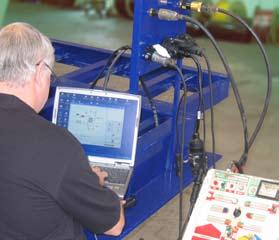
2 Content Contents Introduction Minimum System Specification Page 2 Installation Options Page 3 ECU Connnections Page 4 Secondary Displays Page 6 Setting system parameters Page 7 ECU Configuration Page 8 Load Plate Data entry Page 11 Setting Auxiliaries Page 13 Colas Page 13 Retarder and Trailer Lamp Page 15 ILAS-E Page 16 Lift Axle Page 17 Steer Axle Lock Page 18 Service Lamp, Overload Lamp Page 19 Remote Overload Lamp Page 20 Stability Lamp Page 20 General Purpose Output Page 20 Traction Assist, Info Point Page 21 Tilt Angle Sensing Page 22 Lining Wear Sensor Page 23 General Purpose Input Page 24 Control Line Sensor, Soft Docking Page 25 Mechanical Height Sensor Page 25 Lateral Accelerometer Page 26 Electric Brake Demand Page 27 Extra Lift Axle Data Menu Page 29 Setting Wheel Scaling Page 30 Test for Number of Teeth Page 30 Lamp Settings Page 30 Info - Trailer Information Page 31 Saving the ECU Parameters Page 32 Printing Load plate label Page 33 Setting the Trailer EBS warning lamp Page 34 Reading/deleting diagnostic codes Page 35 Reading Extended diagnostic codes Page 36 Reading Lining Wear Sensor Page 37 Reading Modification Record Page 38 Reading History of Flash Programmin of ECU Page 38 Reading system pressures, speeds Page 39 and voltage End-Of-Line Test Procedure Page 40 End-of-Line Test Report Page 43 Automated End-of-Line Test Page 44 Diagnostics Trouble Codes (DTC) Page 45 Troubleshooting Page 48 With DIAG + you can use a standard personal computer to read and delete diagnostic codes, program vehicle parameters and End-of-line-Test the EB + system. The PC Interface pod allows communications between a standard PC and an ECU. Connections to the PC interface are made through a cable connecting to a USB port on the computer and another cable connecting the diagnostic interface pod to the ECU. The vehicle parameter data is stored inside the EB + ECU. It will remain intact even after electrical power is removed from the EB + system. Note: EB + Interface Pod is different to the Interface Pod as used on MODAL / MODULAR ABS systems. Minimum system specification The minimum PC or Laptop specification to run the DIAG + package is as follows: Processor or above RAM - 8 Megabytes (16 recommended) Hard Drive - 20 Megabytes Monitor x 600 VGA Minimum MS Windows 98, ME, XP, NT, 2000 and vista In addition to the above, a CD drive is required for software installation and USB port required to connect to the interface pod. 2

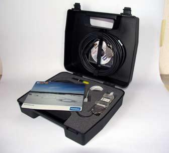
3 Installation Options- Please follow in the order shown The software must be installed before the connection of the interface. 1. The Hardware The DIAG + Interface kit is comprised of the PC Interface pod, together with its connecting cables and a transit case. The pod is provided with a multi function LED to confirm correct function of the unit as follows: Orange: Indicates connection to USB port. The DIAG+ Interface kit The USB pod Alternative positions The USB pod. Red: Indicates connection to USB and EB+. Green: To indicate data is being transmitted. 2. The Software Switch on your machine and enter into the desktop mode of your PC. Insert the DIAG + CD into your PC. Follow the on screen instructions to install the program in the relevant Language. The files are installed in the PC folder : C:\Program Files\Haldex\Diag+ Also Sub folders are installed as follows : C:\Program Files\Haldex\Diag+\DTC Reports C:\Program Files\Haldex\Diag+\ECU Setup files C:\Program Files\Haldex\Diag+\EOL Reports Option 1. OR Option 2. PC Interface PC Interface Now Click the button marked "USB" on the screen to install the USB driver. 3. Installation Options Installation Option 1 Gently push the USB cable into a USB port on the back of your PC or Laptop. Access the EB+ ECU via side-ofvehicle connector. ISO Interface assembly Installation Option 2 Gently push the USB cable into a USB port on the back of your PC or Laptop. Access the ECU by using ISO pin connector which uses pin 6 and 7 as a CAN data bus using ISO interface Assembly ( ) Installation Option 3 Gently push the USB cable into a USB port on the back of your PC or Laptop. Access the ECU directly. Option 3. Connect to ECU directly or via side-of-vehicle connector Diagnostic connection 'DIAG' on ECU PC INTERFACE Power the EB + system from an external 24V supply and the LED light on the interface pod should now be on, coloured red. If it is not, please check your connections and try again. Installation is now complete. The installation program for the USB driver is in a sub-folder on the CD called "USB" should you need to distribute it seperately. 3 Please keep your installation software in a safe place in case you need to reinstall at any point.

4 ECU Connections ECU Connections - Semi, Centre axle Trailers Make all required connections to the ECU 1 - Power supply ISO Backup power supply ISO1185 (24N) 3 - DIAG port 4 - Sensor S2A 5 - Sensor S1A* 6 - Sensor S1B* 7 - Sensor S2B 8 - AUX1 9 - AUX AUX AUX AUX5 *Minimum requirement for a 2S/2M system Note: It is possible to use the DIAG + software to set the ECU parameters with only the power supply ISO7638 connected, i.e. without any other connections 4 to14, but diagnostic codes will be logged and will require to be deleted on final vehicle installation. Power up the EB + ECU. During the self-check procedure the system displays the following functions: 1 - The Trailer EBS warning lamp comes ON and stays ON. 2 - One audible cycle is produced by the EPRV's (EBS valves). Red/Green LED At the same time the LED on the PC interface pod will illuminate 'RED/GREEN' to show that it is receiving a power supply from the ECU. Enter into the DIAG + program by the short-cut icon created on your desktop. The following 'Normal' screen 'should appear. DIAG+ Understanding the main screen display 1 - Browser window (e.g.. EB+ System layout (EOLT)) 2 - Video screen 3 - 'End-of-line Test' (EOLT) procedure 4 - Reset the ECU 5 - Exit the DIAG + program 6 - EB + ECU Version number 7 - System Warning Lamp 8 - System Information Lamp 9 - Chassis Number 10 - Power Source indicator 11 - Interface Version number 12 - Read/Delete Diagnostic Trouble Codes (DTC) 13 - Read, Setup and Program the ECU 14 - Odometer reading (Total distance) and 15 - PC connection port indication

 connected, i.e. without any other connections 1 and 4 to 12, but diagnostic codes will be logged and will require to be deleted on final vehicle installation.")
5 ECU Connections ECU Connections Make all required connections to the EB+ Gen 2 Assembly or Master ECU on 3M system 1 - Power Supply ISO N Power B connection OR Interconnecting cable on 3M system 3- DIAG+ port 4 - Sensor S2A 5 - Sensor S1A 6 - Sensor S1B 7 - Sensor S2B 8 - AUX1 9 - AUX AUX AUX AUX5 EB+ Gen 2 Assembly/Master ECU on 3M Full Trailers 3M system Make connection to the Slave ECU 2 - Interconnecting cable Slave ECU 2 NOTE: It is possible to use the DIAG + software to set the ECU parameters with only the power supply ISO7638 and Interconnection cable (Master to Slave ECU) connected, i.e. without any other connections 1 and 4 to 12, but diagnostic codes will be logged and will require to be deleted on final vehicle installation. On entering into the DIAG + program the following 'Normal' screen should appear appear (See page 6 for secondary main screen displays). 5

6 Secondary Main Screen Displays Secondary main screen displays A flashing 'Warning' symbol indicates EB+ system warning. This alternates with the following symbols:- A flashing 'Spanner' symbol. This indicates presence of a 'Active' Diagnostic Trouble Code. Click on button to Read/Delete DTC. Or you can access the active DTC from the hyperlink. A flashing 'Gauge' symbol. This indicates the reservoir pressure is below 4.5 bar or above 9.8 bar. Note: End of line Test reservoir pressure requires to be 1 bar above laden brake output pressure to the Trailer. 6
7 Setting System Parameters Setting System Parameters Click button picture on right "Read, Setup and Program the ECU". The following screen will appear. Understanding the screen display 1 - Read ECU Configuration from disc Note: To read this file you must enter the 'Edit' ECU parameters section (3). 2 - Read Configuration info from ECU Note: To read this file you must enter the 'Edit' ECU parameters section (3). 3 - Edit ECU parameters and Configuration 4 - Save ECU Configuration to disc 5 - Program ECU with current Configuration info. 6 - Print current ECU Configuration information - Load Plate 7 - OK - Exit the 'Program ECU' menu Program ECU To edit the ECU parameters and Configuration click on button '3'. The following screen will appear. Understanding the screen display 1- Walk through button 2 - Setup the ECU configuration and layout 3 - Setup loadplate configuration 4 - Display trailer information 5 - Setup aux configuration data 6 - Setup wheelscale configuration 7 - Setup lamp flash configuration 8 - OK - Exit the ECU setup ECU Configuration Click on button on the ECU setup screen. The following (1 of 6) screen will appear. a) 2M Side x Side b) 1M (EB+ Gen1 only) c) 2M Axle x Axle d) 2M Non Integrated (EB+ Gen1 only) e) 3M Full Trailer f) 3M Semi Trailer The configuration group title is shown at the top right of the screen in which below are left and right arrow boxes to enable to toggle between the configuration screens. Click on one of the boxes on the left side of the table selecting your system layout. A view on the right side of the table is the chosen ECU configuration and layout. Note: The ECU Configuration has a default setting of: 3 Axle trailer, 2 Sensors on centre axle, ECU left hand installation. 7
 this adjusts the working parameters in the presence of a REV.")
8 ECU Configuration ECU Configuration If box 1 is selected this adjusts the working parameters in the presence of TrCM. If box 2 is selected (as shown) this adjusts the working parameters in the presence of a REV. If box 3 is selected (as shown) Load Sensing function is available together with ABS on Backup powering (ISO1185 (24N)). If box 4 is selected, any automatic lift axles will not raise until move away (when the lamp goes out). It is to enable roller testing of all axles even when unladen. (Note: Use for the UK vehicle test authority). If box 5 is selected (as shown) this allows the weight of the trailer to be indicated in the cab if the truck supports this function. If box 6 is selected this eliminates crossing of the sensor cables Note: Boxes 1-2 you can select one or the other, boxes 3-6 you can select from none to all. Click on button marked to accept


9 ECU Configuration 1M configuration screen. EB+ Gen1 systems only. Note: Position of ECU can be left, right, front or rear. 2M Axle x Axle configuration screen. 2M Non Intergrated configuration screen. EB+ Gen 1 systems only. 9


10 ECU Configuration 3M Full Trailer configuration screen. 3M Semi Trailer configuration screen. Click on button marked to accept. The following screen will appear. 10
11 Load Plate Data Entry Load Plate Data entry Click on button For Semi and Centre axle Trailers the following screen will appear. The screen shows a set of default example values (1 to 5 and 10 to 12) which require to be entered in accordance to the vehicles brake calculation. Highlighting the appropriate box enables you to edit the value or pressing the tab button on your PC will step through, one by one, the various boxes to be edited or selected. The following example shows values entered from a HALDEX brake calculation as shown below. Note: If values 6, 7, 8, and 9 are required (see brake calculation example below) To enter the values click on Use boxes. 6 Use PP1 (Control) PP1 (Delivery) Laden Use PP2 (Control) PP2 (Delivery) Laden PP3 Laden If value 'P Limit' is required, this limits the pressure at the brake chambers to the value selected which must be >=5.00 bar (Note: not derived from brake calculation). To enter the values click on Use P Lim box (default value is 8.50 bar). OUTPUT (Bar) Click on button marked to accept. Example: The graph shows the brake demand pressure (INPUT) values are in relation to the brake delivery pressure (OUTPUT) values. PP2(Delivery)Laden 9 PP1(Delivery)Laden 7 12 PD (Delivery) P0 (Threshold) PP3 Unladen 10 INPUT (Bar) Haldex brake calculation example Input datas for the EBS-Modulator EB+: control pr. pm 6.50 control pr. pm 3 4 P bar Axle Axle load unladen (Kg) Bag press. unladen (bar) 1 12 Brake press. unladen (bar) Axle load laden (Kg) Bag press. laden (bar) 2 Brake press. laden (bar) bar bar bar 11

 Bag press.")
12 Load Plate Data Entry Load Plate Data entry For Full Trailers the following screen will appear. The screen shows a set of default values For a Master and a Remote ECU which require to be entered in accordance to the vehicles brake calculation. The following examples shows values entered from a HALDEX brake calculation as shown below. Click on button marked to accept Haldex brake calculation example- Master ECU Input datas for the EBS-Modulator EB+: RAG Axle control pr. pm 6.50 bar Axle load unladen (Kg) Bag press. unladen (bar) Brake press. unladen (bar) control pr. Axle load laden (Kg) 9000 pm Bag press. laden (bar) P0 PD P bar Brake press. laden (bar) bar Click on button marked to accept Haldex brake calculation example - Remote ECU Input datas for the EBS-Modulator EB+: FAG control pr. pm 6.50 bar control pr. pm bar Axle Axle load unladen (Kg) Bag press. unladen (bar) Brake press. unladen (bar) Axle load laden (Kg) Bag press. laden (bar) P0 PD P1 P2 P3 Brake press. laden (bar) bar 12
 Wheel Scaling - 306 rev/km, 520 Rdyn (mm) and 100 No. of teeth exciter Lamp Sequence - ON/OFF If these are correct go to Trailer information Click on button The following screen will appear.")
 Highlight option and click to select it. The required parameters for that option are automatically set. To view the set parameters click on button marked Modify.")
13 Setting Auxiliaries - COLAS Setting Auxiliaries Click the appropriate screen for setting the auxiliaries The following parameters have default settings as shown below : Auxiliaries - Not used (Unused) Wheel Scaling rev/km, 520 Rdyn (mm) and 100 No. of teeth exciter Lamp Sequence - ON/OFF If these are correct go to Trailer information Click on button The following screen will appear. The screen shows the various Auxiliary connections that can be used (i.e. AUX 1 to 3, 4 and 5). Clicking on arrow displays a listing of options that can be selected. Selecting options COLAS (on Aux 1) Highlight option and click to select it. The required parameters for that option are automatically set. To view the set parameters click on button marked Modify. Example COLAS (AUX 1,2 & 3) The following screen will appear modify the values as required. Duration : Time Colas solenoid is energised (Default 5s) On Speed : The output to the Colas will be switched ON (Default 15 Kph) Off Speed : The output will be switched OFF either when the vehicle decelerates below the 'Off Speed' or when 'Duration' has been exceeded, whichever happens first. (Default 0 Kph) Note: By setting the 'Duration' to 0 sec. this now becomes a speed signal and a 'On and Off Speed' has to be set. Click on button marked to accept. 13
 Different settings for special applications: 1.")

14 Setting Auxiliaries - COLAS COLAS Settings Information General: Activation (On) Speed must be higher than De-activation (Off) speed. (Default for use with COLAS RTR: Duration: 5s, ON: 15 kph, OFF: 0kph) Different settings for special applications: 1. Permanent Output If the duration is set to '0', then the solenoid will switch ON after crossing the 'On Speed' threshold, without a time limitation. It will only switch OFF when the 'Off Speed' is crossed. You can use this setting e.g. to drive an external device that needs power and a C3 speed signal, that is always supplied on the yellow wire of the 3 core Aux cable of Aux 1. (E.g.: 0 s, 15 kph, 10 kph) 2. Movement Detection WITH time limitation If the activation speed is set to '0', then the solenoid will switch ON after 1/4 turn any wheel, irrespective of speed. When the wheel pulses from the sensor stop, the solenoid will switch PFF, also if the Duration is exceeded. (E.g.: 10 s, 0 kph, 0 kph) 3. Movement Detection WITHOUT time limitation Like possibility 2. but 'Duration' must be set to '0'. output is continuously switched ON during moving. (0 s, 0 kph, 0 kph) COLAS Input Functions Colas function can be controlled/extended by several inputs. OR AUX ouput will change status, if COLAS function OR ANY of the related inputs is active. AND AUX output will change status, if COLAS funtion AND ALL related inputs are active. 24V Standard output: COLAS function AND/OR logic HIGH -> 24V to solenoid, otherwise 0V 0V Inverted output: COLAS function AND/OR logic HIGH -> 0V to solenoid, otherwise 24V Application Examples: 1. Traction Help signal can be used to reset the suspension to ride height at the same time. 2. Automatic reset to Ride Height can be switched off if needed. 3. Reset to Ride Height can be started by a remote switch. 4. Customer specific, speed related functions can be controlled by the input. * The output level can be adjusted independently of input use! * Possible inputs: Super Aux A/B/C/ Custom, General Purpose Input (GPI) AUX 4 /5 14
15 Setting Auxiliaries - Retarder and Trailer Lamp Retarder and Trailer Lamp Settings Information Function can be controlled/extended by several inputs. OR AUX output will change status if the function OR ANY of the related inputs are active. AND AUX output will change status if the function AND ALL related inputs are active. 24V Standard output: Function AND/OR logic HIGH -> 24 V to solenoid, otherwise 0 V. 0 V Inverted output: Function AND/OR logic HIGH-> 0 V to solenoid, otherwise 24 V. *The output level can be adjusted independently of input use! *Possible Inputs: SuperAux A/B/C Custom, General Purpose Input (GPI) AUX 4/5 15
 Manual = Manual raise / auto lower. Requires a 24V signal/switch on the yellow wire of the 3 core AUX cable.")
16 Setting Auxiliaries - ILAS-E Example ILAS -E (AUX 1,2 & 3) Front & Rear Auto raise / auto lower. The following screen will appear, modify the values as required. Drop: Example ILAS -E Manual (AUX 2 & 3) Manual = Manual raise / auto lower. Requires a 24V signal/switch on the yellow wire of the 3 core AUX cable. The following screen will appear, modify the values as required. Drop: The pressure where the ILAS solenoid is de-energised resulting the axle to drop. (Default - 90 %) Raise: The pressure where the ILAS solenoid is energised resulting for the axle to raise. (Default - 50 %) Sensor Configuration: Disables the wheel speed signal when a sensed axle is raised. (Default - Not Sensed) Raise with speed, Drop with speed are further options that can be selected when the drop and raise pressures are reached. The pressure where the ILAS solenoid is de-energised resulting the axle to drop. (Default - 90 %) Raise: The pressure where the ILAS solenoid is energised resulting for the axle to raise. (Default - 50 %) Sensor Configuration: Disables the wheel speed signal when a sensed axle is raised. (Default - Not Sensed) Raise with speed, Drop with speed Options are not valid. Raise 'ILAS-E Front' & Raise 'ILAS E-Rear' - Happens fully automatically below the Raise Threshold - In the case of two lift axles the one with the HIGHER Raise Threshold raises first! Raise 'ILAS-E Front Manual' - Happens only after a demand signal on the AUX port (yellow wire) or related control inputs (momentary or permanent signal) - The first activitation is always carried out using the traction assist thresholds. If after exceeding the traction speed limit the lift axle drop threshold is not exceeded the axle remains up, otherwise it is dropped. It will be raised again after dropping below the traction speed limit if you have used a permanent latching switch. Raise 'ILAS-E Rear Manual - Happens only after a demand signal on the AUX port (yellow wire) or related control inputs (momentary or permanent signal) Note: For installations with ILAS -E use: Front lift axle only =ILAS-E Front Middle lift axle only =If lifting it weights the king pin then ILAS-E Front Rear lift axle only =ILAS-E Rear Two axles lifted i.e. Front and Rear = ILAS-E Front + ILAS-E Rear Lower - Happens in both cases automatically after exceeding the Drop Threshold - In the case of two lift axles the one with the LOWER Drop Threshold drops first! Raise with Speed -> 2 possibilities, the HIGHER value will be used 1. In the ECU Setup screen select 'Lift on Move' then ALL lift axles will not raise until vehicle has first exceeded 7 kph after ignition on! 2. AND/OR here in this screen select 'raise with Speed' (option 'Drop with Speed' becomes available and can be selected if necessary). Corresponding speeds must be set in the 'Extra Lift Axle Data' screen (Default: 50 km/h, 1km/h) Sensor Configuration - ILAS-E Rear - If sensors are fitted to the lift axle you have to specify, if not a DTC may be generated when moving! 16
17 Setting Auxiliaries - ILAS-E Traction Help/Disable Lift Axles - ILAS-E Front - Activated by demand signal on AUX port (yellow wire) OR related inputs - Corresponding thresholds must be set in the 'Extra Lift Axle Data' screen (Default: 130 %, 30 kph) Traction Help/Disable Lift axle 'ILAS-E Rear' - Works only if no ILAS-E Front is programmed - Activated by a demand signal on the Aux port (yellow wire) OR related inputs - Corresponding thresholds must be set in the 'Extra Lift Axle Data' screen (Default: 130 %, 30 kph) Lift Axle Info Lift axle functions can be controlled/extended by several inputs. These inputs don't control the outputdirectly as in other cases. In this case inputs are logically connected to the YELLOW wire of the Aux port. With the yellow wire you can control manual lift axles and traction support and you get the same result if you use one or more of the SuperAux or GPI Inputs. AUX Power Settings Information AUX Power function can be controlled / extended by several inputs. By default this fuction is HIGH. OR <<PLEASE DON'T USE>> AUX Output status will never change. This setting has no effect. AND AUX Output will change status, if ALL related inputs are active. 24 V Standard Output: AND logic HIGH -> 24 V to solenoid, otherwise 0 V. 0 V Inverted output: AND logic HIGH-> 0 V to solenoid, otherwise 24 V. Application Examples: 1. Switchable power supply for customer applications. If you use AUTOMATIC lift axles, only the Input for ILAS E Front is used. OR AUX Traction Support is started if the Yellow Wire (Aux 2/3) OR ANY of the Inputs are Active AND <<Note: Yellow wire must only be used on AUX 2/3 >> AUX Traction Support is started if the Yellow Wire AND ALL of the Inputs are active. 24 V Standard Output: Function AND/OR Logic HIgh -> 24 V to solenoid, otherwise 0 V. 0 V Inverted output: Function AND/OR logic HIGH-> 0 V to solenoid, otherwise 24 V. *The output level can be adjusted independently of input use! *Possible Inputs: SuperAux A/B/C Custom, General Purpose Input (GPI) AUX 4/5 AUX Power Settings Information AUX Power function can be controlled / extended by several inputs. By default this fuction is HIGH. 17
 Unlock: Speed at which the steer axle unlocks (Default 20 Kph) Lift Axle Dependence: The steer axle is set to lock and unlocks when")
18 Setting Auxiliaries - Steer Axle Lock Example Steer Axle Lock (AUX 1,2 & 3) The following screen will appear modify the values as required. Lock Above: Speed at which the steer axle locks (Default 25 Kph) Unlock: Speed at which the steer axle unlocks (Default 20 Kph) Lift Axle Dependence: The steer axle is set to lock and unlocks when the front axle is lifted in order to maintain turning circle. Invert Steer Axle Lock This function will reverse the values as stated above in the steer axle lock. By default this function provides 24V to lock a steer axle, 0V otherwise. You can invert the output to get 0V to lock, 24V otherwise. Which output type you need depends on the locking device/pneumatic installation. This 'Inverting' of the output can be selected in two places: 1. Here in this screen -> is usable with all ECU software versions, but inverts only the output of this function. If you don't want to use further control inputs (or cannot because not available) you should use this option. 2. In the main aux screen -> only usable with ECU software version B407 upwards. This option offers the advantage that related control inputs also create an inverted aux output. Example: Automatic Steer Axle Lock function 'HIGH' OR Reversing 'HIGH' (e.g. Super Aux B). Result: In both cases you get 0V Output to lock. IMPORTANT: Only use one of the 'Inversion' options! Otherwise you may get unexpected results! Special case for speed setting: If you set both speeds to '0' the function only locks depending on the lift axle position or related control inputs. Speed no longer has an influence! Steer Axle Lock Settings Information Steer Axle Lock function can be controlled/extended by several inputs. It is possible to lock the steer axle for example on the following events: - Reversing - Demand Signal(s) from a switch mounted in the cab or on the trailer panel - Depending on the front lift axle position - Depending on the speed thresholds Note: AUX is awlays active during ABS events OR AUX Output will change status if steer lock function OR ANY of the related inputs are active. AND AUX Output will change status, if ALL related inputs are active. 24 V Standard Output: Function AND/OR logic HIGH -> 24 V to solenoid, otherwise 0 V. 0 V <<Don't use this option if you intend to use the invert option in the steer lock function>> Inverted output: Function AND/OR logic HIGH-> 0 V to solenoid, otherwise 24 V. *The output level can be adjusted independently of input use! *Possible inputs: SuperAux A/B/C Custom, General Purpose Input (GPI) Aux 4/5 18
19 Setting Auxiliaries - Service Lamp, Overload Lamp Service Lamp Settings Information Function can be controlled/extended by several inputs. OR AUX Output will change status if function OR ANY of the related inputs are active. AND AUX Output will change status, if the function AND ALL related inputs are active. 24 V Standard Output: Function AND/OR logic HIGH -> 24 V to solenoid, otherwise 0 V. 0 V Inverted output: Function AND/OR logic HIGH-> 0 V to solenoid, otherwise 24 V. *The output level can be adjusted independently of input use! *Possible inputs: SuperAux A/B/C Custom, General Purpose Input (GPI) Aux 4/5 Overload Lamp (AUX 1, 2 & 3) For Semi / Centre axle Trailers This gives a 24V output when the trailer load goes above the set limits. The following screen will appear modify the values as required. Note: Overload lamp works with ONLY THE MAIN (master ECU) Valve suspension Input. Overload Lamp Settings Information Function can be controlled/extended by several inputs. OR AUX Output will change status if function OR ANY of the related inputs are active. AND AUX Output will change status, if the function AND ALL related inputs are active. 24 V Standard Output: Function AND/OR logic HIGH -> 24 V to solenoid, otherwise 0 V. 0 V Inverted output: Function AND/OR logic HIGH-> 0 V to solenoid, otherwise 24 V. *The output level can be adjusted independently of input use! *Possible inputs: SuperAux A/B/C Custom, General Purpose Input (GPI) Aux 4/5 19


20 Setting Auxiliaries - Remote Overload Lamp, Stability Lamp, GPO Remote Overload Lamp Select remote Overload Lamp on AUX 1/2/3 and click on 'Modify' button. This gives a 24 V output when the tariler load goes above the set limits. Thefollowing screen will appear to modify the values required. Note: Remote overload Lamp works with ONLY THE Slave ECU Valve suspension unit in 3M full trailer systems. Settings Information Function can be controlled/extended by several inputs. OR AUX Output will change status if function OR ANY of the related inputs are active. AND AUX Output will change status, if the function AND ALL related inputs are active. 24 V Standard Output: Function AND/OR logic HIGH -> 24 V to solenoid, otherwise 0 V. 0 V Inverted output: Function AND/OR logic HIGH-> 0 V to solenoid, otherwise 24 V. *The output level can be adjusted independently of input use! *Possible inputs: SuperAux A/B/C Custom, General Purpose Input (GPI) Aux 4/5 Stability Lamp Settings Information Function can be controlled/extended by several inputs. OR AUX Output will change status if function OR ANY of the related inputs are active. AND AUX Output will change status, if the function AND ALL related inputs are active. 24 V Standard Output: Function AND/OR logic HIGH -> 24 V to solenoid, otherwise 0 V. General Purpose Output (GPI) Settings Information External devices can be controlled by the neutral General Purpose Output (GPO). By default the function is LOW. OR AUX Output will change status if function OR ANY of the related inputs are active. AND << PLEASE DON'T USE>> AUX Output will change status, if the function AND ALL related inputs are active. 24 V Standard Output: Function AND/OR logic HIGH -> 24 V to solenoid, otherwise 0 V. 0 V Inverted output: Function AND/OR logic HIGH-> 0 V to solenoid, otherwise 24 V. 0 V Inverted output: Function AND/OR logic HIGH-> 0 V to solenoid, otherwise 24 V. *The output level can be adjusted independently of input use! *Possible inputs: SuperAux A/B/C Custom, General Purpose Input (GPI) Aux 4/5 20 *The output level can be adjusted independently of input use! *Possible inputs: SuperAux A/B/C Custom, General Purpose Input (GPI) Aux 4/5

21 Setting Auxiliaries - Traction Assist, Info Point Traction Assist (TA+) Settings Information Function can be controlled/extended by several inputs. OR AUX Output will change status if function OR ANY of the related inputs are active. AND AUX Output will change status, if the function AND ALL related inputs are active. 24 V Standard Output: Function AND/OR logic HIGH -> 24 V to solenoid, otherwise 0 V. 0 V Inverted output: Function AND/OR logic HIGH-> 0 V to solenoid, otherwise 24 V. *The output level can be adjusted independently of input use! *Possible inputs: SuperAux A/B/C Custom, General Purpose Input (GPI) Aux 4/5 Info Point Info Point is used to show different events/system faults by an ORANGE Point. In the DIAG+ 'Info Point Status' screen you can see what causes the indication. Here you can set the following options: ENABLE - ORANGE point is only ACTIVE as long as the event is active STORE - ORANGE point is ACTIVE until the Info Point has been reset (vehicle service) This can be done by clearing he system DTC's with DIAG+ or Info Centre or by cycling the ignition ON for 4 seconds, OFF, ON for 4 seconds, OFF, then ON (the same sequence can be used to clear lining wear indicators) DTC - All detected DTC's cause an Info Point indication SERVICE INDICATOR - Anything that causes the Service Indicator will cause an Info Point indication (e.g. linings worn or service due) - The Service Indicator is normally shown by 2 flashes of the Yellow Warning Lamp OVERLOAD - Up to 150 %, default is 130 % when no value is shown - During 'Traction Help' monitoring is switched off OVER SPEED - Up to 150 km/h, default is 100 km/h when no value is shown OVER PRESSURE - Up to 12 bar, default is 9.75 bar (DTC trigger level) when no value is shown - Legistlation allows max 8.5 bar reservoir pressure - Higher pressure reduces the life time of all pneumatic components OVER VOLTAGE - Up to 32 V, default is 32 V (DTC trigger level) when no value is shown ATTENTION: With the combined function 'Info Point/Colas' the refresh of the Info Point is only started if the speed is higher than 15 km/h, because simultaneously the ride height is reset. 21

22 Setting Auxiliaries - Tilt Angle Sensing Tilt Angle Sensing This auxiliary function energises an Auxiliary output if, when Stability is enable, the trailer is detected as exceeding a user defined level of tilt at low speeds. This is usually associated with tipper trailers where the vehicle can fall over when discharging load. If fitted to an Auxiliary with an additional input then this input can be used to energise the output if the input is active. This is usually used to prevent the tipper from tipping the load if a tail gate switch detects that the tailgate is in the closed position. It can be set from 2 to 15 degrees. ECU version C440 onwards. Settings Information Function can be controlled/extended by several inputs. OR AUX Output will change status if function OR ANY of the related inputs are active. AND AUX Output will change status, if the function AND ALL related inputs are active. 24 V Standard Output: Function AND/OR logic HIGH -> 24 V to solenoid, otherwise 0 V. 0 V Inverted output: Function AND/OR logic HIGH-> 0 V to solenoid, otherwise 24 V. *The output level can be adjusted independently of input use! *Possible inputs: SuperAux A/B/C Custom, General Purpose Input (GPI) Aux 4/5 22

. Custom screen The 'Service Lamp Flash' is set as default. A sequence of three lamp flashes on ECU power up.")
23 Setting Auxiliaries - Lining Wear Sensor AUX 4 & 5 Options Lining Wear Sensor Select Lining Wear Sensor from the drop down menu. Then select modify to enter specific parameters. The following screen appears. 'Lining Wear Indicator'. From the menu select one of the following: Haldex LWI BPW/Brake Monitor (customer specific only) Custom Haldex LWI' and 'BPW Brake Monitor' are preprogrammed options and no other data is required. 'Custom' allows entry of user settings (see Custom screen below). Custom screen The 'Service Lamp Flash' is set as default. A sequence of three lamp flashes on ECU power up. 'Continuous Flash' causes the flashing to continue until the vehicle is first driven away from rest. The Custom screen allows the user to enter custom voltage settings as to an alternative manufacturer lining wear system used. Note: As the pads wear the input voltage can rise or drop. If the lining wear sensor is tampered (i.e.short circuited) the input voltage rises. 23

24 Setting Auxiliaries - GPI AUX 4 & 5 Options General Purpose Input (GPI) Select 'General Purpose Input' from the drop down menu. Then select 'modify' to enter specific parameters. The following screen appears. 'General Purpose Input: [AUX4]. The actions from this screen are processed if the conditions are active. The Yellow Warning Lamp can be 'permanent' or only on whilst the conditions are 'active'. You can connect simple switches or any type of 5 V sensor (Pressure sensor 0-8 bar, M16x1.5 is available from Haldex) AUX cable colours and function: RED; Output 5 V Supply BLACK; B- YELLOW; Input Signal, analog (0-24 V) You can use the 'Output' (High, Low) to control other auxiliaries. Application examples: 1. Traction help for lift axle by switch mounted on the trailer and /or in the cab. 2. Monitoring spring brake pressure, warning lamp if lower limit is exeeded. 3. Allow additional functions perhaps only if spring brake is 0 bar (i.e. brake applied) NOTE: The lamp usage is controlled by ECE-R13 24
. It is available in Gen 2 software B397 onwards. To fit a control line sensor, pressure switch must be first replaced by a new control line sensor.")
25 Setting Auxiliaries - Control Line Sensor, Soft Docking, Mechanical Height Sensor Control Line Sensor Control Line Sensor functionality was added to EB+ ECU software B399 (gen 1 1M/2M) and B400 (Gen 1 3M). It is available in Gen 2 software B397 onwards. To fit a control line sensor, pressure switch must be first replaced by a new control line sensor. The existing pressure switch cable can still be used but must be swapped from the ECU end from PSW socket to either the AUX 4 or AUX 5 socket. After this has been done, it can be programmed using the DIAG+ via the auxiliary set up screen. Soft Docking There are currently no options for Soft Docking that can be set by the user. Mechanical Height Sensor The mechanical height sensor is for use on mechanical suspension trailers. It will allow the EB+ to measure load and therefore adjust braking force according to the load plate data. To configure the mechanical height sensor the user must first enter the trailer deflection. This is given by the trailer manufacturer and we allow 10mm to 65mm. Once the deflection is entered, the user must set the lever length to between the allowed lever length range. The allowed lever length range varies depending upon the deflection. E.g. a deflection of 20 mm will allow a lever length range of 100 to 151 mm and a deflection of 55 mm will allow a lever length range of 276 to 320 mm. Once the lever length is set, the user then enters the actual lever length. The user now selects a left or right installation. The mechanical height sensor also needs calibrating which is performed during EOLT. To perform calibration the trailer must be fully unladen. 25

26 Setting Auxiliaries - Lateral Accelerometer AUX 5 Options Lateral Accelerometer (EB+ Stability) for 2M Systems ONLY Support for External Accelerometer AUX 5 - Option On the following ECU part Nos Version A256 or later Version A256 or later This AUX Configuration must be used. Select 'Lateral Accelerometer' to calibrate EB+ Stability. Support for Internal Accelerometer On the following ECU part Nos This AUX Configuration must be used. To set the parameters click on button marked 'Internal' The following screen will appear. Click on box 'Internal Accelerometer' to select installation. Note: A additional Auxiliary test runs specifically for the Internal Accelerometer Reaction to Various Configuration Possibilities Make sure the correct Aux Configuration is chosen i.e. External mounted on AUX 5 or Internal (within the ECU). Errors that will occur are as follows: Accelerometer will not work. A stability sensor DTC will be recorded. 26
27 Setting Auxiliaries - Electric Brake Demand Electric Brake Demand Electric Brake Demand is an internal feature that allows application of the brakes under certain conditions by electrical inputs. No ISO CAN or pneumatic demand required. This feature is very flexible and can be used for a lot of applications. To set the parameters click on button marked 'Internal' The following screen will appear. Click on box 'Electric Brake Demand' to select installation. Select Default Settings Load the default settings for these three known applications. Modifications are allowed, but then it is no longer a DIAG+ default setup. - Street Laying Machine - Bogie / Inter Lock - Extendable Drawbar / Trailer Cab warning Lamp (ECE R-13) Driver can be informed by ABS warning lamp if EBD active. - None - Yellow Lamp - Red Lamp + Buzzer (CAN ISO7638) (Only on Bogie/ Inter Lock option) Speed Threshold ( km/h) Enable below - below this speed it's possible to switch EBD feature ON Disable above - above this speed EBD will be switched OFF automatically Internal Demand Pressure ( bar) This pressure will be delivered 1:1 to the actuators, if the following option ('Load apportion..') is not selected. If this option is selected you'll get load dependant output,(lsv active) corresponding to the demand pressure. Option 'Output bar...' generates a higher output, if the current setting is not high enough under special conditions (big gradient during street building..). To achieve this, the pneumatic demand pressure must be higher than the current EBD demand pressure for a short period of time. 27


28 Setting Auxiliaries - Electric Brake Demand Options - Keeps lift axles down as long as this feature is active, this avoids height changes of trailer chassis - If the 'Disable Speed' was crossed during operation and therefore the EBD feature is switched OFF, the control input must be reset once to switch the feature ON again - If the control input is already active during ignition ON, it must be Reset once to switch the feature ON again The last two options avoid unexpected activation of the feature. Electric Brake demand Info By default 'EBD' feature is inactive and must be controlled by external input/switch! ('EBD' = Electronic Brake Demand) The following inputs can be used: available with all GEN1 and GEN2 EB+ (ECU C440 upwards): GPI4 = AUX4 connected to a switch, yellow core as signal input GPI5 = AUX5 connected to a switch, yellow core as signal input Additional, if you use SuperAux EB+ variant: -Input A, B, C available on Power B connector - Several of these inputs (A and/or B, A and/or C, B and/or C) - or customer specific combination of these inputs (modify screen) If you select more than one input, they are used corresponding to the selected logic: ((Input A active) AND/OR (Input B active)) -> Action The brake will be applied if the current speed is below EBD 'Enable Speed' threshold AND the logic is also valid. OR Brake will be applied if ONE of the inputs is active AND <<only useful with more than one selected input>> Brake will be applied if ALL related inputs are active. 28
.")
.")
29 Setting Auxiliaries - Lift Axle Extra Lift Axle data menu To view a set of parameters click on button marked 'Modify'. The following screen will appear. Raise Speed If the option RAISE WITH SPEED is set for ANY lift axle, then the axle will not lift before the set speed (The default is 50 km/h). Example is for manoeuvring before getting on to the highway. Drop Speed If the option DROP WITH SPEED is set for ANY lift axle, then the axle will drop automatically the vehicle speed falls below the set speed (The default is1 km/h). Traction Overload limit The Traction Assist axle will drop once the suspension reaches this value, based on % of laden setting. An INFORMATION icon is displayed above 130% to ask the user to check the design weights for the remaining axle(s) as the legal limit is 130% of design weight. (The default is 130%). Traction Speed limit The Traction Assist axle will drop once the vehicle speed increases above the value (The default is 25 km/h). A warning icon is displayed above 30 km/h to indicate that this is above the legal limit. Action on 5 sec Press Normally, when the Lift Axle Switch has been pressed for 5 s, the system assumes that the switch is a PERMANENT type, not a MOMENTARY type. If the "Disable Lift Axle" option is selected then the system will ALWAYS assume that the switch is MOMENTARY and will disable (lower) all lift axles until the system is next re-powered (ignition off). 29
 with a 100 tooth exciter installed. This value covers tyre sizes from 19.5\" to 22.")
30 Setting Wheel Scaling, Test for number of teeth, Lamp Settings Setting Wheel Scaling Click on button The following screen will appear. The screen shows the default value of a tyre size of 306 revs/km, 520 Rdyn (Dynamic rolling radius - mm) with a 100 tooth exciter installed. This value covers tyre sizes from 19.5" to 22.5" and sets the correct ABS function and odometer of the system. Note: If the tooth number is not 100 the wheel scale factor on the Info Centre will read a different value. Click on button marked to accept. Test for number of teeth Click on button Click on button marked 'Start - Turn Wheel 5 Times' Rotate the Select Sensed wheel 1rev/ 2sec, five times. The Pulses box automatically records during the wheel rotation procedure. After 5 turns, click on button marked 'Stop'. The 'No. Of Teeth' box indicates the value. Click on button marked 'Use Calculated Value' if required to use in wheel scaling above or note the value for information purposes. Click on 'Abort' to exit. Repeat for any other selected sensor Stop Use Calculated Value Lamp Settings Abort Click on button The following screen will appear. The screen shows the two options of flash sequence for the trailer EBS warning lamp. The ON/OFF sequence is set as a default. Click on button marked to accept. Note: The ON/OFF lamp sequence change will only be visible if system air pressure is above 4.5 bar. Lamp Settings On / Off / On On / Off 30
 Brake Calculation Number (16 characters) Chassis Number (17 characters) Type (12 characters)")
 This information is stored in the ECU and can be printed out on the End-of-line Test report and")

31 Info - Trailer Information Info - Trailer information Click on button The following screen will appear. Enter details of : Trailer Manufacturer (19 characters) Brake Calculation Number (16 characters) Chassis Number (17 characters) Type (12 characters) Axle Information - Load of axle/s installed on the trailer. (Default values are: Unladen =3000 Kg, Laden=9000Kg) This information is stored in the ECU and can be printed out on the End-of-line Test report and load plate. By clicking button opens a new screen titled 'Geometric Data'. From here the user can enter detailed vehicle data. - Configuration - Lift Axle Position - Wheel Base From Software version C463/C464/C465 onwards, the EB+ transmits 'Geometric Data' to the truck via the ISO11922 CAN link. Click on button marked to accept. 'ECU setup' is complete (ECU parameters settings not sent to ECU - see next step). Click on button marked to accept. 31
 can be entered in position 'File Name' and stored in the C:\Program Files\Haldex\Diag+\ECU Setup files folder. Click on button 'Save' to store the file.")

 FLASHING - programmed ECU (with an 'ECU setup' installed) Note: The trailers EBS warning lamp is ON This completes the programming of the ECU. The following screen will appear.")
32 Saving ECU Parameters Saving the ECU parameters OPTION 1 Saving the ECU parameters file to disc Click on button The following screen will appear. A file name (e.g. EXAMPLE 01 saved as type.dpf) can be entered in position 'File Name' and stored in the C:\Program Files\Haldex\Diag+\ECU Setup files folder. Click on button 'Save' to store the file. Note: The saved EB + ECU parameter file can be used for future programming of ECU's (which require the same parameters) by recalling the file from the 'Open EB + ECU File' button. OPTION 2 Programming the ECU Click on button This activates the sending of the edited parameters file to the ECU. Note: At 90% progress all the DTC's are deleted and the ECU is reset. The status of this process is shown in the following ways: 53 - A bar indicator fills the progress box on the 'Program ECU' screen 54 - The trailers EBS warning lamp function is - a) ON - ECU not programmed b) FLASHING - programmed ECU (with an 'ECU setup' installed) Note: The trailers EBS warning lamp is ON This completes the programming of the ECU. The following screen will appear Send/Read file Click button to view or print a label with the current ECU configuration information (Load plate label). 32


33 Printing Load Plate Label Printing Load Plate Label Print label using Haldex blank label Use Laser printer only and refer to manufacturers information on printing a A5 size paper. After installation spray on a clear lacquer (or a hard varnish) to protect the printed surface. Example label for a Semi or Centre axle Trailer Untitled - DiagPrint To align the print on the blank paper to be within the cut out margins use from the top menu 'File', 'Page Offset' command. The following screen will appear. Use the vertical/ horizontal sliders to make the adjustment for the appropriate printer. On completion of the label printing Click on button to on the appropriate screens return to the main screen. Example label for Full Trailer Reset the ECU by clicking button or switch power to the ECU OFF but DO NOT EXIT THE DIAG + PROGRAM 33
34 Setting Trailer EBS Warning Lamp Setting the trailer EBS warning lamp After Resetting wait 10 secs before proceeding further. Observe the trailer EBS warning light. The warning lamp should display what has been set in the 'Lamp Setting' section of the ECU Setup. A Note: If the EBS warning light comes ON and stays ON and the main screen displays as on page 6 there are Diagnostic Trouble Codes (DTC) present which need to be cleared or if the system air pressure is below 4.5 bar. Click on the button on Main screen 'A' also on DTC's, Lining Wear and Modification Records screen 'B' to show any stored DTC's B If there are no DTC's detected the following screen will appear. Click on button to accept EXIT THE DIAG + PROGRAM. 34
35 Reading/Deleting DTC's Reading/Deleting diagnostic codes (a) Click on the button on Main screen also on DTC's, Lining Wear and Modification Records screen The following screen's will appear. Screen Option 1: If there is a Current DTC it will be displayed in red 1st on the list. If there are other DTC's listed they have been stored in the ECU memory. Repair the current DTC and reset the ECU by pressing the button or switch power to the ECU off. Screen Option 2: If there is NO Current DTC it will display 'No Active DTC's' in red. Any other DTC's are stored which can be deleted. (b) Click on the button marked to delete the Stored DTC's (c) The following screen will appear. Click button marked to exit. The 'DIAG+' main screen will appear. (d) Reset the ECU by clicking button or switch power to the ECU OFF but DO NOT EXIT THE DIAG + PROGRAM. (e) Observe the trailer EBS warning light. The warning lamp should display what has been set in the 'Lamp Setting' section of the ECU Setup. Note: If the EBS warning light comes ON and stays ON there are DTC's present which need to be cleared as above or if the system air pressure is below 4.5 bar.. The following screen will appear and should display no DTC's Note: If further DTC's are present repeat procedure (b) to (e) EXIT THE DIAG + PROGRAM. 35
. The event is logged every time the ECU is powered.")
36 Reading Extended DTC's Reading Extended diagnostic codes On Active and Stored DTC's double click on any DTC or select button to display the extended DTC information. The following screen appears. Understanding the main screen display 1. The number of times the DTC occurred (Max 254 events). The event is logged every time the ECU is powered. The following data relates to the 1st time the DTC occurred. 2. Date reading. Recorded when a Info Centre is installed. Updated every 10 mins. (Example shows no Info Centre) 3.Odometer reading (Total distance) 4. Volts Reading 5. Reservoir pressure (Full information available on ECU version A272 onwards) 6. Suspension bag pressure(full information available on ECU ver A272 onwards) 7. Speed at which the DTC occurred (Example shows vehicle stationary) 8. Electric control line pressure CAN lines pins 6,7 on ISO 7638(Example shows a 5 pin ISO 7638 installed) 9. Pressure reading on the Service (Yellow) line while braking. 10. Total time, from ECU power up, when DTC occured 11. Description of DTC 12. Order and quantity of DTC/s 13. Slow wheel recovery 14. Status Flags of signal requests and system information refer to Haldex for further interpretation. 15. Flashing Icons: DTC from ECU DTC from file 16. Read Extended DTC file from disc Note: To read this file you must enter the 'Extended DTC Information' screen. 17. Save Extended DTC file to disc. 18. Print Extended DTC 19. Exit Note: This button will detail each diagnostic trouble code for example "Wheel speed sensor continuity". 36
.")

 In the Brake Pad Replacments column the 'Needs Change' is replaced by a figure in Km. b) The 'Status Of Current Pads' indicator changes from Red to Green.")
37 Reading Lining Wear Sensor Reading Lining Wear Sensor Note: This feature must be set in AUX Configuration - AUX 4 -Option. Click on the button and check if a DTC 'AUX 4' is listed. If identified click on button to enter the Lining Wear Info lining wear info screen. The following screen's will appear which lists the history of the changes of Linings (last five recorded). The left hand column records when the brake pads (lining wear sensor) has worn. The right hand column records or indicates when the brake pads have been replaced or require replacing. If the 'Status of current pads' indication is coloured Red and the Info indicates 'Needs Change' exit Diag+ switch power off to ECU and repair appropriate lining/s. Re-enter to Diag+ and 'Lining Wear Info' screen. Red Click button marked The following screen appears. Click on button marked 'OK'. The following should occure: a) In the Brake Pad Replacments column the 'Needs Change' is replaced by a figure in Km. b) The 'Status Of Current Pads' indicator changes from Red to Green. Lining Wear Info On 'Lining Wear Info' screen click Button marked to exit to Main screen. Note: Diagnostic code 'Aux4' is deleted automatically. When linings are in good condition or to review the 'Lining Wear Info' screen enter as described above. The following screen will be displayed. The 'Status of current pads' indication is coloured Green Record any necessary details for future reference. Green 37

38 Reading Modification Record/History of Flash Programming of ECU Reading Modification Record Click on the button on Main screen also 'BLUE box 'on DTC's, Lining Wear and Modification Records screen The following screen appears. This is a record of when the ECU has been programmed. The user can be the computers name or log on name or 'Info C' representing Info Centre. The display shows up to ten recent users. Click button marked to exit. Reading History of Flash Programming Of ECU Click on the button 'RED box ' on DTC's, Lining Wear and Modification Records screen The following screen appears. Works by displaying the last ten Flash Programming Events, sorted most recent first, in the same manner as DIAG+ Programming Record. When the ECU flash memory is reprogrammed to version B310/B311 or later, a record is made in the ECU memory (containing details of the computer used, the date and the ECU version). Test Jan B321 Test Dec B318 Note: Records from older ECU versions will display a message of 'No data available!'. Click button marked to exit. 38
39 Reading System Pressures, Speeds and Voltage Reading system pressures, speeds and voltage Connect Emergency and Service pressure lines. Observe the values of the system pressures and voltage on the browser window which shows the schematic of the EB+ system. Example: the following should be displayed 1) Pressure values are from the Load Plate Data entry shown on page 10 for an Unladen trailer. The reservoir pressure is shown as 6.5 Bar minimum but can be whatever is used in the workshop. 24 Volts 6.5 Bar 0.6 Bar 1.75 Bar 6.5 Bar 1.75 Bar 4.3 Bar 2) Pressure values are from the Load Plate Data entry shown on page 10 for a Laden trailer. 24 Volts 5.9 Bar 6.5 Bar 6.5 Bar 5.9 Bar On rotation of the sensed wheels the speed value will be displayed. Example: 1 rev / 2 sec (30 rpm) ~ 4 kph for 80 tooth 5 kph for 90 tooth 6 kph for 100 tooth 24 Volts 6.5 Bar 0.6 Bar 2 kph 1.75 Bar 6.5 Bar 1.75 Bar 39 2 kph

 Completion of an EOLT b) An existing EOLT file is opened (.")

40 End-of-Line test Procedure Clear all Active or Stored Diagnostic Trouble Codes before proceeding with End-of-Line Test. NB: When the ECU is initially programmed all DTC's are deleted End-of-Line Test Procedure Click on the button on main screen. The following screen's will appear. With the correct interface and ECU versions used Ensure Warning notes. Continue Test, click to proceed with next step. The 'View/print' and 'Save to file' buttons are initially disabled. They are enabled under the following conditions: a) Completion of an EOLT b) An existing EOLT file is opened (.eol) ('View/print' only) 'Embedded Software Version' screen If the interface or ECU are not compatible (i.e. wrong versions) Click to quit the EOLT procedure. Update appropriate version. Embedded Software Version Unable to Proceed with End Of Line Test! Dongle Version is OK (G229 or later) ECU Version needs to be G231 or later 'WARNING' screen If there is no pressure measured at PORT 41 check installation piping. EOLT Initialisation A listing of tests are shown. The boxes marked indicate the tests to be carried out. The tests can be selected or de-selected as required. If the 'Pause Between Tests' option is not selected, the selected tests screen will run automatically after each test has been carried out. If the 'Operators Name' option is selected, it will enable a name to be entered in the area below. This will be recorded on the EOLT report. Note: The Screen display as shown is relevant to a 2 Modulator system. The Sensor-Modulator tests is a combination of the Sensor output to the correct Modulator. Sensor Test Rotate each wheel through 3 revolutions in 5 seconds. Result section: YELLOW indicates wheel spinning fast enough. GREEN indicates test passed. RED indicates DTC generated during test. Note: On each of the following test screens there is a button marked. This gives on-screen information about test to be carried out. If the trailer information has been entered (see page 18 - 'Info') with the Vehicle Ident Number then this will be displayed in the tiltle bar of each test as 'VIN 17_figure_chassis'. 40
41 Sensor - Modulator Test Sensor- Modulator Test Rotate each wheel through 1 revolutions in 2 seconds. The system should brake the spinning wheel. Result section: YELLOW indicates wheel has moved. GREEN indicates test passed. RED indicates test failed. Push Through Pressure Test APPLY BRAKE The system should be forced into push-through condition (approx. 1:1) and the delivery pressures will be measured. RELEASE BRAKE The TARGET pressure is a calculated value. The 'Main Valve Port 1' and 2 boxes displays the actual pressure that is measured at the EPRV. For 3M systems the actual pressure is displayed in the 'Remote Valve' box. Push-Through Tests - VIN 17_figure_chassis Apply Brake Target Main Valve Port Main Valve Port 12 Remote Valve Result section: YELLOW indicates test started. GREEN indicates test passed. RED indicates test failed. EBS Pressure Function Test (Automatic test) The system will be forced to simulate various load conditions and control pressures. The delivery pressures will be measured and compared with the target pressures. Push-Through Tests - VIN 17_figure_chassis Target Release Brake Main Valve Port Main Valve Port Remote Valve Result section: YELLOW indicates test started. GREEN indicates test passed. RED indicates test failed. Note: The example shows the screen as for a 2M Side by Side installation. For 3M a two screens appear '3M Master 'and '3M Remote' Note: Before this test a Warning screen may appear. Make sure that there is the required air pressure in the reservoir to carry out the test. Failure results may occur on the output values (P3) if the value measured (-0.3 bar min.) is below the target value. Push-Through Tests - VIN 17_figure_chassis Target (Bar) Main Valve Port Main Valve Port Result Unladen Laden P0 PD PP1 PP2 MAX PP1 PP2 MAX 2M Side by Side Diag+ WARNING - Reservoir Pressure is close to Maximum Test Pressure 41 OK

42 Lamp and Auxiliaries Test, EOLT Reports Lamp and Auxiliaries Test (Automatic test) The Cab Lamp and any auxiliaries will be forced ON then OFF, and monitored to determine the correct response. Once correctly tested, the lamp or auxiliary can be switched manually without affecting test results. To switch to manual testing click on the 'On' button the 'Off' and 'Norm' buttons are highlighted, Toggle between the 'On' and 'Off'. The 'Norm' resets to automatic mode. Result section: YELLOW indicates test started. GREEN indicates test passed. RED indicates test failed. AUX5 tests the (External) Lateral Accelerometer (EB+ Stability) if selected in the AUX Configuration option (see page 14). If the test failes refer to EB+ Stability installation Instructions and check chassis installation. OR INT tests the Internal Lateral Accelerometer (EB+ Stability) if selected in the AUX Configuration option 'Internal' (see page 16). If the test fails refer to EB+ Installation Instructions and check chassis installation. Aux3 On Off Norm INT On Off Norm Is trailer level? Calibrate? If EITHER Lateral Accelerometer has ALREADY BEEN PROGRAMMED, then an option is given to skip the calibration step, e.g.repeat EOLT no longer on level ground. The following screen appears Test Complete Yes Return To EOLT Menu No Click on button marked to accept. The following screen appears EOLT Options EOLT Reports The End of line Test report can be viewed by selecting the button. If required the report can then be printed. Before Proceeding with End Of Line Test Secure the Vehicle against movement. 2. Release the Parking Brake. By selecting the button a report file can be saved. A file name relevant to the vehicle tested (e.g. TRAILER01 saved as type.eol) can be entered in position 'File Name' and stored in the C:\Program Files\ Haldex\Diag+\EOLT Reports folder. Save EOLT Report File Save in EOLT Reports Trailer01.eol? Note: The EOLT report can only be viewed within DIAG+ program in the EOLT section (refer to page 27 - Sec a) 42 File Name: Trailer02.eol Save as type EOLT Report Files Save Cancel
43 End of Line Test Report Haldex EB+ End of Line Test Report 43

 and save to a new file. The print icon will allow you to print the load plate data.")

44 Automated End-of-Line Test Automated End of Line Test (OEM recommended only) The auto end of line test enables a parameter file to be opened for a trailer, program the ECU, rest and check for faults, fix any faults, perform end of line test and save and print in sequence from one base window. Fom the start screen, select the icon commence the auto End of Line Test. to The screen Automated End of Line Test will appear. It will display live pressure information. Note: P41_2 also appears in case of 3M systems. It is possible to check or edit the data (perhaps to change the VIN or auxiliary function) and save to a new file. The print icon will allow you to print the load plate data. The forward button will proceed with the end of line test for the trailer. The operator name can be preset in the INI file, and can be locked out if required. It is not possible change the tests selected in the INI file, as they are greyed out. The End of line test will then proceed once the ticked icon is selected. Once the automated End of line test is complete and no faults identified, you should see this screen. The option is given to print out the report. 44
1. Semi- and centre-axle trailers To enable the automatic load sensing function to operate, it is necessary to define certain parameters as follows:
 Commercial Vehicle Systems Product DATA Function Load Sensing Function (pneumatic suspension) PD-4-F00 The Load Sensing Function (LSF) of the TEBS Brake Module is used to replace the function of a load
DATA PD ES1305. Product. Trailer ABS (KB4TA) Function
 Function") V Commercial Vehicle Systems Product DATA PD-203-300 Function The Knorr-Bremse KB4TA module is an integrated ABS electronic control unit and dual modulator valve for air braked trailers with mechanical
V Commercial Vehicle Systems Product DATA PD-203-300 Function The Knorr-Bremse KB4TA module is an integrated ABS electronic control unit and dual modulator valve for air braked trailers with mechanical
INSTALLATION GUIDE. Electronic Braking System. Innovative Vehicle Solutions
 INSTALLATION GUIDE Electronic Braking System Innovative Vehicle Solutions EB+ Gen3 Installation guide Notes on the use of this manual This manual has been designed to assist personnel in satisfactory installation
DATA PD-214-F101. TEBS G2 Doc. No. Y (EN - Rev. 001) July Product. Lift Axle Control. Function. Operation
 July Product. Lift Axle Control. Function. Operation") Commercial Vehicle Systems Product DATA Function Many trailers have one or more axles having the capability of being lifted so that they carry none of the trailer load. The function is present in the TEBS
Commercial Vehicle Systems Product DATA Function Many trailers have one or more axles having the capability of being lifted so that they carry none of the trailer load. The function is present in the TEBS
Operator s Guide ELECTRONIC BRAKE SYSTEMS EB+ GEN 2.
 Operator s Guide ELECTRONIC BRAKE SYSTEMS EB+ GEN www.haldex.com Contents Page EB+ GEN Operator s guide General Components Guide 3 System Layout Chassis Components 5 System Diagnostics 6 Warning Device,
. For 4S/3M applications an Integrated Speed Switch (ISS)
") Commercial Vehicle Systems Product DATA PD-203-430 Function The Knorr-Bremse KB4TA module is an integrated ABS electronic control unit and dual modulator valve for air braked trailers (semi-trailers, centre-axle
Commercial Vehicle Systems Product DATA PD-203-430 Function The Knorr-Bremse KB4TA module is an integrated ABS electronic control unit and dual modulator valve for air braked trailers (semi-trailers, centre-axle
EPAS Desktop Pro Software User Manual
 Software User Manual Issue 1.10 Contents 1 Introduction 4 1.1 What is EPAS Desktop Pro? 4 1.2 About This Manual 4 1.3 Typographical Conventions 5 1.4 Getting Technical Support 5 2 Getting Started 6 2.1
Features: ECUtalk enables the user to:
 Features: ECUtalk enables the user to: Retrieve information from the ECU: - General - Error status - Configuration Change the ECU s configuration Check System components Carry out EOL tests Generate Load
REV F2.0. User's Manual. Hydraulic ABS (HABS) Hydraulic Power Brake (HPB) Page 1 of 28
 Hydraulic Power Brake (HPB) Page 1 of 28") REV F2.0 User's Manual Hydraulic ABS (HABS) Hydraulic Power Brake (HPB) Page 1 of 28 Table of Contents INTRODUCTION...4 Starting TOOLBOX Software... 5 MAIN MENU...6 System Setup... 6 Language... 7 Select
REV F2.0 User's Manual Hydraulic ABS (HABS) Hydraulic Power Brake (HPB) Page 1 of 28 Table of Contents INTRODUCTION...4 Starting TOOLBOX Software... 5 MAIN MENU...6 System Setup... 6 Language... 7 Select
Issue 2.0 December EPAS Midi User Manual EPAS35
 Issue 2.0 December 2017 EPAS Midi EPAS35 CONTENTS 1 Introduction 4 1.1 What is EPAS Desktop Pro? 4 1.2 About This Manual 4 1.3 Typographical Conventions 5 1.4 Getting Technical Support 5 2 Getting Started
Operating and Installation BPW THE QUALITY FACTOR. Version 1.4. ECO Tronic EBS. Operating and Installation Instructions. Version 1.
 Operating and Installation Instructions Version.4 BPW THE QUALITY FACTOR ECO Tronic EBS. Operating and Installation Instructions Version.4 BPW Operating and Installation Instructions Introduction Page.
To increase the height of the trailer increase the length, to reduce the height, decrease the length of the link.
 RIDE HEIGHT (CONTINUED) 8.8.2. Trailer Suspension The trailer suspension is set at the factory and should always return to this setting when the height control valve is returned to the central position,
EBS and More. What can you do with advanced braking systems? Chair : Mario Colosimo. Robert Smedley, Knorr Bremse Ian Thomson, BPW Transpec
 EBS and More What can you do with advanced braking systems? Chair : Mario Colosimo Panel : Neil Chilton, Warnambool Cheese and Butter Robert Smedley, Knorr Bremse Ian Thomson, BPW Transpec Trailer Electronic
Innovative Vehicle Solutions
 INSTALLATION Installation GUIDE Guide Innovative Vehicle Solutions U-ABS Installation Guide Notes on the use of this manual This manual has been designed to assist personnel in satisfactory installation
Overview of operation modes
 Overview of operation modes There are three main operation modes available. Any of the modes can be selected at any time. The three main modes are: manual, automatic and mappable modes 1 to 4. The MapDCCD
User Manual. Compact Tester II st Edition
 User Manual Compact Tester II 446 300 430 0 1st Edition This publication is not subject to any update service. You will find the new version in INFORM under www.wabco-auto.com Copyright WABCO 2006 Vehicle
Advanced User Manual
 Advanced User Manual Banks SpeedBrake For use with Palm Tungsten E2 2004-2005 Chevy/GMC 6.6L (LLY) Turbo-Diesel Pickup THIS MANUAL IS FOR USE WITH KITS 55419 & 55421 Gale Banks Engineering 546 Duggan Avenue
ITCEMS950 Idle Timer Controller - Engine Monitor Shutdown Isuzu NPR 6.0L Gasoline Engine
 Introduction An ISO 9001:2008 Registered Company ITCEMS950 Idle Timer Controller - Engine Monitor Shutdown 2014-2016 Isuzu NPR 6.0L Gasoline Engine Contact InterMotive for additional vehicle applications
Begin to Use The New ESC: Before use the new ESC please carefully check every connections are correct or not. Yellow motor wire B Blue motor wire A
 HIMOTO ZTW Brushless Electronic Speed Control for car or truck Thank you for purchasing ZTW Brushless Electronic Speed Controller(ESC). The ZTW electronic speed control (ESC) is specifically designed for
Nemesis-TCS system manual release /11/2011 Author Mick Boasman. UK Tel
 Nemesis-TCS Traction Control System Firmware TCS 2 cylinder 1.21 onwards Firmware TCS 4 cylinder 1.08 onwards TC-Pod 1.05 WinTC Software 1.11 -User Onwards 2 cylinder WinTC Software 2.04 -User Onwards
Instruction of connection and programming of the VECTOR controller
 Instruction of connection and programming of the VECTOR controller 1. Connection of wiring 1.1.VECTOR Connection diagram Fig. 1 VECTOR Diagram of connection to the vehicle wiring. 1.2.Connection of wiring
FOUR-WHEEL ANTI-LOCK BRAKE SYSTEM (4ABS)
") 35B-1 GROUP 35B FOUR-WHEEL ANTI-LOCK BRAKE SYSTEM (4ABS) CONTENTS GENERAL INFORMATION 35B-2 35B-6 SENSOR 35B-6 ACTUATORS 35B-6 ABS-ECU 35B-7 35B-2 The ABS that ensures directional stability and controllability
35B-1 GROUP 35B FOUR-WHEEL ANTI-LOCK BRAKE SYSTEM (4ABS) CONTENTS GENERAL INFORMATION 35B-2 35B-6 SENSOR 35B-6 ACTUATORS 35B-6 ABS-ECU 35B-7 35B-2 The ABS that ensures directional stability and controllability
Feature Description. Version History
 TA2 Malfunction Indicator Lamp (MIL) and Engine Protection Document Number: FD-0007 Author: J. Goodloe Version: 03 Publish Date: 2016-03-18 Feature Description Version History Version Date Modified Sections
Idle Timer Controller - ITC515-A Ford Transit Contact InterMotive for additional vehicle applications
 An ISO 9001:2008 Registered Company Idle Timer Controller - ITC515-A 2015-2018 Ford Transit Contact InterMotive for additional vehicle applications Overview The ITC515-A system will shut off gas or diesel
CurveMaker HD v1.0 2Ki Programmable Ignition programming software
 Contents CurveMaker HD v1.0 2Ki Programmable Ignition programming software Dynatek 164 S. Valencia St. Glendora, CA 91741 phone (626)963-1669 fax (626)963-7399 page 1) Installation 1 2) Overview 1 3) Programming
PCS GEAR SELECT MODULE USER GUIDE v4.0
 PCS GEAR SELECT MODULE USER GUIDE v4.0 Ph: 1.804.227.3023 www.powertraincontrolsolutions.com Powertrain Control Solutions 1 Introduction 1.1 Included Components 1 - GSM Cable Motor Enclosur 1 - GSM Driver
An ISO 9001:2008 Registered Company
 An ISO 9001:2008 Registered Company Introduction Engine Monitor System 2009-2018 Ford E Series (EMS501-D) 2008-2010 Ford F250-550 6.2L, 6.8L (EMS506-D) 2011-2016 Ford F250-550 6.2L, 6.8L (EMS507-D) 2017
INSTALLATION/SERVICE MANUAL. Intelligent Trailer Control Module (L31286)
") MANUAL TM Intelligent Trailer Control Module (L31286) Important Notice The products described within this literature, including without limitation, product features, specifications, designs, availability
MANUAL TM Intelligent Trailer Control Module (L31286) Important Notice The products described within this literature, including without limitation, product features, specifications, designs, availability
SIDE ROLL SENSOR TROUBLESHOOTING GUIDE
 SIDE ROLL SENSOR TROUBLESHOOTING GUIDE WARNING Service the roll sensor(s) only if you are an authorized technician. The roll sensor triggers airbags and seat restraints. Accidental deployment could cause
Pull the relevant lever whilst holding in the air lock switch, lift until both air locks have released.
 3.1.1. Lowering Decks 3.1.2.1. Pull the relevant lever whilst holding in the air lock switch, lift until both air locks have released. 3.1.2.2. Push the lever whilst still holding the air locks open and
DATA PD LS1..., LS2..., LS3... Lift Axle Valves - Pneumatic. P r o d u c t. Function. Technical Features
 C o m m e r c i a l V e h i c l e S y s t e m s P r o d u c t DATA PD-503-200 Function Pneumatic Lift Axle Control Valves are used for the semi-automatic or fully automatic control of air suspended lift
PowerJet Sequential Injection INDEX. 1 Introduction 1.1 Features of the Software. 2- Software installation
 INDEX 1 Introduction 1.1 Features of the Software 2- Software installation 3 Open the program 3.1 Language 3.2 Connection 4 Folder General - F2. 4.1 The sub-folder Error visualization 5 Folder Configuration
SiCan Simple CAN Extension Charger to PacMon
 SiCan Simple CAN Extension Charger to PacMon Provides and extension charger to PacMon. Drives CAN TC (Elcon) type chargers. Interfaces with the CMon, SiMon, and UMon. Programmable high and low (balance)
ANTI-LOCK BRAKING SYSTEM (ABS)
") 35B-1 GROUP 35B ANTI-LOCK BRAKING SYSTEM (ABS) CONTENTS GENERAL DESCRIPTION 35B-2 35B-5 INTRODUCTION TO 35B-5 ABS DIAGNOSTIC TROUBLESHOOTING STRATEGY 35B-5 DIAGNOSTIC FUNCTION 35B-6 DIAGNOSTIC TROUBLE
35B-1 GROUP 35B ANTI-LOCK BRAKING SYSTEM (ABS) CONTENTS GENERAL DESCRIPTION 35B-2 35B-5 INTRODUCTION TO 35B-5 ABS DIAGNOSTIC TROUBLESHOOTING STRATEGY 35B-5 DIAGNOSTIC FUNCTION 35B-6 DIAGNOSTIC TROUBLE
QUICK INSTALLATION GUIDE
 MANUAL/AUTOMATIC T R A N S M I S S I O N 2 - B U T T O N R E M O T E S T A R T E R W I T H V I R T U A L T A C H S Y S T E M ( A S P R G - 1 0 0 0 C O M P A T I B L E ) QUICK INSTALLATION GUIDE Manual
MapDCCD Version 2 Installation and setup guide
 MapDCCD Version 2 Installation and setup guide Overview of operation modes There are three main operation modes available. Any of the modes can be selected at any time. The three main modes are: manual,
QUICK START GUIDE. (407) /
 /") QUICK START GUIDE (407) 774-2447 / www.sctflash.com SECTION 1: PARTS + CHECKLIST X4 DEVICE MICRO USB CABLE HDMI/OBD II CABLE TOOLS NEEDED: Fuse Puller Voltage Tester Battery Charger Pliers SECTION 2: PRE-INSTALL
QUICK START GUIDE (407) 774-2447 / www.sctflash.com SECTION 1: PARTS + CHECKLIST X4 DEVICE MICRO USB CABLE HDMI/OBD II CABLE TOOLS NEEDED: Fuse Puller Voltage Tester Battery Charger Pliers SECTION 2: PRE-INSTALL
INDEX. 1.Safety Precautions and Warnings...3
 INDEX 1.Safety Precautions and Warnings...3 2. General Information...5 2.1 On-Board Diagnostics (OBD) II... 5 2.2 Diagnostic Trouble Codes (DTCs)... 6 2.3 Location of the Data Link Connector (DLC)...7
Lift axle control on axle 1. Lift axle control on axle 3
 Commercial Vehicle Systems Product DATA Function On vehicle combinations using semi-trailers it is often difficult to meet the turning corridor required by European Community (EC) legislation. When certain
DATA PD-214-F104. TEBS G2 Doc. No. Y (EN - Rev. 001) May Product. icargo. Function. Operation
 May Product. icargo. Function. Operation") Commercial Vehicle Systems Product DATA Function On semi-trailers and centre-axle trailers, the axle/bogie will act as a pivot point that, depending on the positioning of the cargo carried by the trailer,
Commercial Vehicle Systems Product DATA Function On semi-trailers and centre-axle trailers, the axle/bogie will act as a pivot point that, depending on the positioning of the cargo carried by the trailer,
TRACTION CONTROL SYSTEM (TCL)
") 35C-1 GROUP 35C TRACTION CONTROL SYSTEM (TCL) CONTENTS GENERAL DESCRIPTION 35C-2 DIAGNOSIS 35C-4 INTRODUCTION TO TRACTION CONTROL SYSTEM DIAGNOSIS 35C-4 TCL DIAGNOSTIC TROUBLESHOOTING STRATEGY 35C-4 DIAGNOSTIC
35C-1 GROUP 35C TRACTION CONTROL SYSTEM (TCL) CONTENTS GENERAL DESCRIPTION 35C-2 DIAGNOSIS 35C-4 INTRODUCTION TO TRACTION CONTROL SYSTEM DIAGNOSIS 35C-4 TCL DIAGNOSTIC TROUBLESHOOTING STRATEGY 35C-4 DIAGNOSTIC
PIM701 (Police Interface Module) Dodge Charger Pursuit
 Dodge Charger Pursuit") An ISO 9001:2008 Registered Company PIM701 (Police Interface Module) 2015-2017 Dodge Charger Pursuit Introduction The Police Interface Module is intended to provide Dodge Chargers with multiple desired
An ISO 9001:2008 Registered Company PIM701 (Police Interface Module) 2015-2017 Dodge Charger Pursuit Introduction The Police Interface Module is intended to provide Dodge Chargers with multiple desired
HGM6410/6420 AUTOMATIC GENERATOR MODULE WITH J1939 INTERFACE SOFTWARE MANUAL
 HGM6410/6420 AUTOMATIC GENERATOR MODULE WITH J1939 INTERFACE SOFTWARE MANUAL SMARTGEN ELECTRONICS Smartgen Electronic Equipment Co., Ltd No.12 Dongqing Street Zhengzhou Henan Province P.R.China Tel : (0086)-371-67992951
DATA. icargo) Product. Application. Purpose. Function. Knorr-Bremse s intelligent axle loading system, icargo, is designed to work on:
 Product. Application. Purpose. Function. Knorr-Bremse s intelligent axle loading system, icargo, is designed to work on:") Commercial Vehicle Systems Product DATA Doc. No. Y09 (EN - Rev. 00) January 0 Application Knorr-Bremse s intelligent axle loading system,, is designed to work on: Semi-trailers with two to five axles Centre-axle
Commercial Vehicle Systems Product DATA Doc. No. Y09 (EN - Rev. 00) January 0 Application Knorr-Bremse s intelligent axle loading system,, is designed to work on: Semi-trailers with two to five axles Centre-axle
Section 55 Chapter 6
 Section 55 Chapter 6 REMOTE HYDRAULICS CONTROLLER Calibration and Fault Codes 6-12880NH TABLE OF CONTENTS REMOTE HYDRAULICS CONTROLLER CALIBRATION... 55-5 Requirements For Calibration... 55-5 Aux Set Main
The electromechanical parking brake
 Service Training Self-study programme 346 The electromechanical parking brake Design and function To make absolutely sure that the vehicle could not roll away when parked up, the driver had to pull up
INSTALLATION/SERVICE MANUAL
 INSTALLATION/SERVICE MANUAL External Pressure Sensor Transducer Intelligent Trailer (L31295W) haldex.com Important Notice The products described within this literature, including without limitation, product
Trailer brake and chassis control
 COMMERCIAL VEHICLE SYSTEMS BRAKE AND CHASSIS CONTROL Trailer brake and chassis control TRAILER COMPETENCE 2 THE MUNICH-BASED KNORR-BREMSE GROUP IS THE WORLD S LEADING MANUFACTURER OF BRAKING SYSTEMS FOR
Shift Solenoid "A" Performance (Shift Solenoid Valve S1)
") 78 DTC P0751 Shift Solenoid "A" Performance (Shift Solenoid Valve S1) DESCRIPTION The ECM uses signals from the output shaft speed sensor and input speed sensor to detect the actual gear position (1st,
78 DTC P0751 Shift Solenoid "A" Performance (Shift Solenoid Valve S1) DESCRIPTION The ECM uses signals from the output shaft speed sensor and input speed sensor to detect the actual gear position (1st,
INSTALLATION/SERVICE MANUAL
 MANUAL TM Stability Module (L31288W) Important Notices Product Options This manual has been designed to assist personnel in satifactory installation of Haldex ITCM Stability Module onto semi and full trailers.
Indian Speedometer and Body Control Module Service Tool Users Guide
 Indian Speedometer and Body Control Module Service Tool Users Guide Installing speedometer software to your computer 1. Go to the Indian Motorcycle Website: WWW. Indianmotorcycle.com 2. Log in to Service
For questions or technical support, 1. Wiring Reference:
 Warning: Before proceeding you are obligated to read and agree to the terms and conditions attached to this manual. Misuse of this product may cause injury or death. Incorrect installation may cause damage
INDEX 1 Introduction 2- Software installation 3 Open the program 4 General - F2 5 Configuration - F3 6 - Calibration - F5 7 Model - F6 8 - Map - F7
 SET UP MANUAL INDEX 1 Introduction 1.1 Features of the Software 2- Software installation 3 Open the program 3.1 Language 3.2 Connection 4 General - F2 4.1 The sub-folder Error visualization 5 Configuration
Rear Drive Axle and Differential
 Page 1 of 13 Rear Drive Axle and Differential GENERAL Item Part Number Description A - Electronic rear differential B - Open rear differential 1 - Rear driveshaft 2 - Electronic rear differential 3 - RH
ELECTRONICALLY CONTROLLED 4WD
 27C-1 GROUP 27C ELECTRONICALLY CONTROLLED 4WD CONTENTS SERVICE PRES......... 27C-3 SERVICE SPECIFICATIONS....... 27C-3 SEALANT...................... 27C-3 SPECIAL TOOLS................ 27C-4............
Automated Control Electronics (ACE ) System Operation and Diagnostics
 System Operation and Diagnostics") Commercial Products Automated Control Electronics (ACE ) System Operation and Diagnostics PART NO. 98962SL This page is intentionally blank. Table of Contents Introduction... 1 Controller Operation and
Commercial Products Automated Control Electronics (ACE ) System Operation and Diagnostics PART NO. 98962SL This page is intentionally blank. Table of Contents Introduction... 1 Controller Operation and
ANTI-LOCK BRAKING SYSTEM (ABS)
") 35B-1 GROUP 35B ANTI-LOCK BRAKING SYSTEM (ABS) CONTENTS GENERAL DESCRIPTION......... 35B-2................ 35B-4 INTRODUCTION TO ANTI-LOCK BRAKING SYSTEM DIAGNOSIS................ 35B-4 ABS DIAGNOSTIC
35B-1 GROUP 35B ANTI-LOCK BRAKING SYSTEM (ABS) CONTENTS GENERAL DESCRIPTION......... 35B-2................ 35B-4 INTRODUCTION TO ANTI-LOCK BRAKING SYSTEM DIAGNOSIS................ 35B-4 ABS DIAGNOSTIC
Quick Setup Guide for IntelliAg Model YP40 20 Air Pro
 STEP 1: Pre-Programming Preparation: The Quick Guide assumes the Virtual Terminal, Master Switch, Working Set Master, Working Set Member, and all sensors have been connected and properly installed. Reference
Idle Timer Controller - ITC Freightliner MT45 Contact InterMotive for additional vehicle applications
 An ISO 9001:2008 Registered Company System Operation Idle Timer Controller - ITC805 2013-2018 Freightliner MT45 Contact InterMotive for additional vehicle applications The ITC805 system shuts down idling
SD Bendix TABS 6 Advanced Single-Channel Trailer ABS Module 1. INTRODUCTION
 SD-13-47671 Bendix TABS 6 Advanced Single-Channel Trailer ABS Module ECU Cover (Sealed) Through-holes for Frame (Chassis) Mounting ECU Part Number Label (See Page 34) 18-Pin Connector 3/8" NPT Load Port
2001 Chevrolet Corvette ACCESSORIES & EQUIPMENT Remote Keyless Entry Systems - Corvette
 DESCRIPTION 2001 ACCESSORIES & EQUIPMENT Remote Keyless Entry Systems - Corvette Remote Keyless Entry (RKE) system is controlled by Remote Function Actuation (RFA) system. Transmitter allows remote control
DESCRIPTION & OPERATION
 DESCRIPTION & OPERATION ANTI-LOCK BRAKING 1998-99 BRAKES Anti-Lock/TCS - Corvette The Anti-Lock Brake System (ABS) and Traction Control System (TCS) increases vehicle control during severe deceleration
Features: Enhanced throttle response, excellent acceleration, linearity and driveability
 120A/150A ESC X-Car 120A/150A Series Sensored/Sensorless Brushless ESC for 1:8 scale Car or Truck Thank you for purchasing the X-Car Brushless Electronic Speed Controller (ESC). The X-Car 1:8 Scale 120A/150A
ANTI-SKID BRAKING SYSTEM (ABS)
") 35B-1 GROUP 35B ANTI-SKID BRAKING SYSTEM (ABS) CONTENTS GENERAL INFORMATION........ 35B-2 SERVICE SPECIFICATIONS....... 35B-3 SPECIAL TOOLS................ 35B-4............ 35B-5 STANDARD FLOW OF DIAGNOSTIC................
35B-1 GROUP 35B ANTI-SKID BRAKING SYSTEM (ABS) CONTENTS GENERAL INFORMATION........ 35B-2 SERVICE SPECIFICATIONS....... 35B-3 SPECIAL TOOLS................ 35B-4............ 35B-5 STANDARD FLOW OF DIAGNOSTIC................
C-PIM701 (Police Interface Module) 2018 Dodge Charger Pursuit
 2018 Dodge Charger Pursuit") An ISO 9001:2008 Registered Company C-PIM701 (Police Interface Module) 2018 Dodge Charger Pursuit Introduction The Police Interface Module is intended to provide Dodge Chargers with multiple desired functions
An ISO 9001:2008 Registered Company C-PIM701 (Police Interface Module) 2018 Dodge Charger Pursuit Introduction The Police Interface Module is intended to provide Dodge Chargers with multiple desired functions
Vehicle makes models and variants known or believed to be using this vehicle system, required diagnostic lead and degree of known compatibility.
 HELLA CRUISE CONTROL - System Overview This is a tiny ECU which is surprisingly versatile and turns up in lots of different places. Sometimes it co exists with an engine management specific interface ECU
Quick Setup Guide for IntelliAg Model YP Air Pro
 STEP 1: Pre-Programming Preparation: The Quick Guide assumes the Virtual Terminal, Master Switch, Working Set Master, Working Set Member, and all sensors have been connected and properly installed. Reference
SHIFT SELECTOR OPERATION AND CODE MANUAL
 SHIFT SELECTOR OPERATION AND MANUAL How to use the shift selector to read oil level and diagnostic codes on 3000/4000 Series Allison transmissions P.O. Box 894, Speed Code 462-470-PF3 Indianapolis, Indiana
SCHEMATIC AND ROUTING DIAGRAMS
 2004 ACCESSORIES & EQUIPMENT Keyless Entry - Corvette SCHEMATIC AND ROUTING DIAGRAMS KEYLESS ENTRY SCHEMATICS Fig. 1: Driver Door Schematic Courtesy of GENERAL MOTORS CORP. Fig. 2: Passenger Door Schematic
2 WAY REMOTE STARTER & ALARM SYSTEM INSTALLATION GUIDE FCC ID NOTICE
 REV. ARS. WAY REMOTE STARTER & ALARM SYSTEM INSTALLATION GUIDE FCC ID NOTICE This device complies with Part 5 of the FCC rules. Operation is subject to the following conditions:. This device may not cause
Product manual Oil Streak Sensor INTRODUCTION CONSTRUCTION. Master Sensor
 Product manual Oil Streak Sensor INTRODUCTION Oil streak sensors are designed to detect traces of oil travelling through air tubes, down to flows as low as 5mm 3 /min. The product utilizes a master and
Document ID# Buick LeSabre
 http://127.0.0.1:9001/servlets/blobshtml?shtmlfile=633088&evc=sm&pubid=262&cellid... Page 1 of 3 Document ID# 633088 DTC C1214 Circuit Description The system relay is energized when the ignition is ON.
Shift Solenoid "B" Performance (Shift Solenoid Valve S2)
") 86 A750E AUTOMIC TRANSMISSION AUTOMIC TRANSMISSION SYSTEM DTC P0756 Shift Solenoid "B" Performance (Shift Solenoid Valve S2) DESCRIPTION The ECM uses signals from the output shaft speed sensor and input
86 A750E AUTOMIC TRANSMISSION AUTOMIC TRANSMISSION SYSTEM DTC P0756 Shift Solenoid "B" Performance (Shift Solenoid Valve S2) DESCRIPTION The ECM uses signals from the output shaft speed sensor and input
XC Instrumentation System Owner s Manual Revision /05/06
 XC Instrumentation System Owner s Manual Revision 3.0 07/05/06 XC INSTRUMENTATION SYSTEM OWNER S MANUAL 1 Revision History Date New Revision Level Revision Description 11/08/05 1.0 Initial release 05/24/06
Power Sliding Door (PSD) Diagnostic Approach. Fixing Intermittent Malfunctions. Power Sliding Door (PSD) Diagnostic Information
 Diagnostic Approach. Fixing Intermittent Malfunctions. Power Sliding Door (PSD) Diagnostic Information") Power Sliding Door (PSD) Diagnostic Information Power Sliding Door (PSD) The power sliding door (PSD) provides built-in diagnostics. This assists the service technicians during troubleshooting. The PSD
Power Sliding Door (PSD) Diagnostic Information Power Sliding Door (PSD) The power sliding door (PSD) provides built-in diagnostics. This assists the service technicians during troubleshooting. The PSD
Idle Timer Controller - A-ITC520-A Ford E Series Ford F250 - F Ford F250 - F550 (*B-ITC520-A) F650/F750
 F650/F750") An ISO 9001:2008 Registered Company Idle Timer Controller - A-ITC520-A 2009-2018 Ford E Series 2008-2016 Ford F250 - F550 2017-2018 Ford F250 - F550 (*B-ITC520-A) 2016-2018 F650/F750 *Uses the Ford 24-Pin
An ISO 9001:2008 Registered Company Idle Timer Controller - A-ITC520-A 2009-2018 Ford E Series 2008-2016 Ford F250 - F550 2017-2018 Ford F250 - F550 (*B-ITC520-A) 2016-2018 F650/F750 *Uses the Ford 24-Pin
HGM1780 AUTOMATIC GENERATOR MODULE CONTENT 1. SUMMARY PERFORMANCE AND CHARACTERISTICS SPECIFICATION OPERATION...
 CONTENT 1. SUMMARY...4 2. PERFORMANCE AND CHARACTERISTICS...4 3. SPECIFICATION...5 4. OPERATION...6 4.1. DISPLAY PANEL...6 4.2. LCD ICON INSTRUCTION...7 4.3. DISPLAY INSTRUCTIONS...7 4.4. DISPLAY DESCRIPTION...8
Function ECU, Wireless
 Commercial Vehicle Systems Product DATA PD-551-000 Function ECU, Wireless The is a Gateway Receiver system to alert the driver if any monitored tyre runs under its normal pressure or above its normal temperature.
Function ECU, Wireless
 Commercial Vehicle Systems Product DATA PD-551-000 Function ECU, Wireless The is a Gateway Receiver system to alert the driver if any monitored tyre runs under its normal pressure or above its normal temperature.
INSTALLATION GUIDE. FCC ID NOTICE
 REV.5 RS. ADVANCED REMOTE STARTER INSTALLATION GUIDE www.security.soundstream.com FCC ID NOTICE This device complies with Part 5 of the FCC rules. Operation is subject to the following conditions:. This
R and R Meritor WABCO Enhanced Easy-Stop Trailer ABS Replacement Kits for Easy-Stop ECU/Modulator Valve Assembly Part Number
 Issued 06-03 Installation Guide Hazard Alert Messages Read and observe all Warning and Caution hazard alert messages in this publication. They provide information that can help prevent serious personal
GENERAL MOTORS SERVICE PARTS OPERATION 6200 Grand Pointe Drive, Grand Blanc, MI 48439
 LS IGNITION CONTROLLER 19355418 Ignition Control for Carbureted LS Series Engines (24x Crankshaft Index/1x Camshaft Index, 58x Crankshaft Index/4x Camshaft Index) Parts Included Quantity Ignition Controller
Technical Service BULLETIN
 Technical Service BULLETIN December 4, 2003 Title: Models: 03 4Runner BR005-03 BRAKES Introduction Some 2003 model year 4Runner vehicles may experience a VSC light ON condition and DTC C1203 in the Skid
Lingenfelter NCC-002 Nitrous Control Center Quick Setup Guide
 Introduction: Lingenfelter NCC-002 Nitrous Control Center Quick Setup Guide The NCC-002 is capable of controlling two stages of progressive nitrous and fuel. If the NCC-002 is configured only for nitrous,
SmarTire TPMS Maintenance Hand Tool. Revision User Manual
 SmarTire TPMS Maintenance Hand Tool Revision 1.04 User Manual Page 2 Table of Contents FCC Compliance Label... 4 User Interface Illustration... 4 Introduction... 5 Testing Tire Sensors... 5 Main Menu...
Shift Solenoid "B" Performance (Shift Solenoid Valve S2)
") 88 A750F AUTOMIC TRANSMISSION AUTOMIC TRANSMISSION SYSTEM DTC P0756 Shift Solenoid "B" Performance (Shift Solenoid Valve S2) DESCRIPTION The ECM uses signals from the output shaft speed sensor and input
88 A750F AUTOMIC TRANSMISSION AUTOMIC TRANSMISSION SYSTEM DTC P0756 Shift Solenoid "B" Performance (Shift Solenoid Valve S2) DESCRIPTION The ECM uses signals from the output shaft speed sensor and input
Ducati 899, 1199 Clutch-Free shifting Perfected This manual is for Blip Box with firmware 1.11 onwards
 Ducati 899, 1199 Clutch-Free shifting Perfected This manual is for Blip Box with firmware 1.11 onwards Welcome to Blip Box, the world s first Plug n Play throttle auto-blip system for Ducati 899 / 1199
Draft Unofficial description of the UNRC charger menus
 Table of contents 1. The main screen... 2 2. Charge modes overview... 2 3. Selecting modes... 3 4. Editing settings... 3 5. Choose default charge mode... 4 6. Edit memory banks... 4 7. Charge mode description...
Isuzu. Chapter Testing Engine and Transmission Systems Engine And Transmission Code Reading Connectors and Locations
 Chapter 10 Isuzu This chapter contains information for testing Isuzu vehicles with the Asian Import Vehicle Communication Software (VCS). The following Isuzu systems may be available for testing: Engine
DESCRIPTION. Chrysler NCV3 Service Info Section 08 > Electronic Modules > MODULE, Transmission Control Information
 DESCRIPTION The transmission control module (TCM) receives, processes and sends various digital and analog signals related to the automatic transmission. In addition, it processes information received
HGM1770 Automatic Generator Control Module OPERATING MANUAL Smartgen Electronic
 HGM1770 Automatic Generator Control Module OPERATING MANUAL Smartgen Electronic CONTENT 1. SUMMARY... 4 2. PERFORMANCE AND CHARACTERISTICS... 4 3. SPECIFICATIONS... 5 4. OPERATION... 6 5. PROTECTION...
ELD DRIVER GUIDE June 21, 2018
 ELD DRIVER GUIDE June 21, 2018 Contents Getting Started with PrePass ELD...4 Enroll in the PrePass ELD Program... 4 For a Carrier Enroll in the ELD Service... 4 For a Driver Get Driver Login Information...
EasyCoding User Manual
 EasyCoding User Manual Table of contests 1. Software operating system... 2 2. Software download and installation... 2 2.1 Software download... 2 2.2 Software installation... 2 3. Product instruction...
LUCAS ACE - System Overview
 LUCAS ACE - System Overview The Active Corner Enhancement system manufactured by Rover Group Lucas appears to have been produced specifically for the Land Rover Discovery series II to address the poor
Aftermarket Interface Module
 An ISO 9001:2008 Registered Company Aftermarket Interface Module (2015-2018 Ford Transit) AIM514-B High Side Solenoid type Coolant Valve Control AIM515-B Motor Reversing type Coolant Valve Control Introduction
Model 1:8 Beast-ZTWSS120A 1:8 Beast-ZTWSS150A. PN#Model Cont.Current 120A 150A. Burst Current 760A 1080A
 Alien Power System BEAST Series Sensored/Sensorless Brushless ESC for 1:8 scale Car or Truck Thank you for purchasing the Alien Power System Brushless Electronic Speed Controller (ESC). The Alien Power
I. CONNECTING TO THE GCU
 I. CONNECTING TO THE GCU GCU7 and newer units use CAN BUS to connect to the computer so special interface is needed. GCU Interface uses FTDI drivers which are usually already installed by default. If you
2007 Chevrolet Corvette STEERING Steering Wheel and Column - Corvette. Steering Wheel and Column - Corvette
 2007 STEERING Steering Wheel and Column - Corvette SPECIFICATIONS FASTENER TIGHTENING SPECIFICATIONS Fastener Tightening Specifications Specification Application Metric English Actuator Retaining Screws
Appendix 3 V1.1B Features
 Appendix 3 V1.1B Features The v1.1b of the Valve Spring Tester adds several new features, which are described in this Appendix. In addition, the Automatic Spring Tester was released after the original
CORNERING LIGHTING MODULE CLM02-CAN INSTALLATION MANUAL
 CORNERING LIGHTING MODULE CLM02-CAN INSTALLATION MANUAL QUASAR ELECTRONICS ul. Cieślewskich 2K 03-07 Warszawa tel. (22) 427-3-4..44 http://www.quasarelectronics.pl e-mail: biuro@quasarelectronics.pl OPERATION