SCHEMATIC AND ROUTING DIAGRAMS
|
|
|
- Darlene Wilkins
- 5 years ago
- Views:
Transcription
1 2004 ACCESSORIES & EQUIPMENT Keyless Entry - Corvette SCHEMATIC AND ROUTING DIAGRAMS KEYLESS ENTRY SCHEMATICS Fig. 1: Driver Door Schematic Courtesy of GENERAL MOTORS CORP.
2 Fig. 2: Passenger Door Schematic Courtesy of GENERAL MOTORS CORP. COMPONENT LOCATOR KEYLESS ENTRY COMPONENT VIEWS
3 Fig. 3: Rear Of Vehicle Component Views - Left Courtesy of GENERAL MOTORS CORP. Callouts For Fig. 3 Callout Component Name 1 Defogger Grid 2 Electronic Suspension Control (ESC) Module 3 Remote Control Door Lock Receiver (RCDLR) KEYLESS ENTRY CONNECTOR END VIEWS Remote Control Door Lock Receiver (RCDLR) Terminal Identification
4 Connector Part Information Way F Micro-Pack 100 Series (BLK) Pin Wire Color Circuit No. Function 1 ORN 540 Battery Positive Voltage 2 PNK 1045 RFA Class 2 Serial Data Not Used 4 BLK 851 Ground DIAGNOSTIC INFORMATION AND PROCEDURES DIAGNOSTIC STARTING POINT - KEYLESS ENTRY Begin the system diagnosis with Diagnostic System Check - Remote Keyless Entry. The Diagnostic System Check will provide the following information: The identification of the control module(s) which command the system The ability of the control module(s) to communicate through the serial data circuit The identification of any stored diagnostic trouble codes (DTCs) and their status The use of the Diagnostic System Check will identify the correct procedure for diagnosing the system and where the procedure is located. DIAGNOSTIC SYSTEM CHECK - REMOTE KEYLESS ENTRY Test Description The numbers below refer to the step numbers on the diagnostic table. 2: Lack of communication may be due to a partial malfunction of the class 2 serial data circuit or due to a
5 total malfunction of the class 2 serial data circuit. The specified procedure will determine the particular condition. 5: The presence of DTCs which begin with "U" indicate some other module is not communicating. The specified procedure will compile all the available information before tests are performed. Diagnostic System Check - Remote Keyless Entry Step Action Yes No 1 Install a scan tool. Does the scan tool power up? Go to Scan Tool Does Not Power Up in Data Link Go to Step 2 Communications 2 1. Turn ON the ignition, with the engine OFF. 2. Attempt to establish communication with the body control module (BCM). Does the scan tool communicate with the BCM? Go to Step 3 IMPORTANT: The engine may start during the following step. Turn OFF the engine as soon as you have observed the Crank power mode. Go to Scan Tool Does Not Communicate with Class 2 Device in Data Link Communications Access the Class 2 Power Mode in the Diagnostic Circuit Check on the scan tool. 2. Rotate the ignition switch through all positions while observing the ignition switch power mode parameter. Does the ignition switch parameter reading match the ignition switch position for all switch positions? Go to Step 4 Select the BCM display DTCs function on the scan tool. Does the scan tool display any DTCs? Go to Step 5 Does the scan tool display any DTCs which begin with a "U"? Does the scan tool display DTC B1000 or B1004? Go to Power Mode Mismatch in Body Control System Go to Symptoms - Keyless Entry Go to Scan Tool Does Not Communicate with Class 2 Device in Data Link Communications Go to Step 6 Go to Diagnostic Trouble Code (DTC) List in Body Control System Go to Step 7
6 7 8 Does the scan tool display DTC B1339 or B1349? Does the scan tool display DTC B1482, B1483, B1507 or B1508? Go to Diagnostic Trouble Code (DTC) List in Body Control System Go to Step 8 Go to Diagnostic Trouble Code (DTC) List in Engine Electrical Go to Diagnostic Trouble Code (DTC) List SCAN TOOL OUTPUT CONTROLS Scan Tool Output Controls Scan Tool Output Additional Menu Control Selection(s) Program Key Fobs Program Key Fobs Program Key Fobs Program Key Fobs 1 Key Fobs 2 Key Fobs 3 Key Fobs 4 Key Fobs Description The BCM requests the Remote Control Door Lock Receiver to enter the Program Key Fobs mode. Refer to Transmitter Programming for additional information. The BCM requests the Remote Control Door Lock Receiver to enter the Program Key Fobs mode. Refer to Transmitter Programming for additional information. The BCM requests the Remote Control Door Lock Receiver to enter the Program Key Fobs mode. Refer to Transmitter Programming for additional information. The BCM requests the Remote Control Door Lock Receiver to enter the Program Key Fobs mode. Refer to Transmitter Programming for additional information. SCAN TOOL DATA LIST The Keyless Entry Scan Tool Data List contains all of the keyless entry related parameters that are available on the scan tool. The parameters in the list are arranged in alphabetical order. The column, "Data List," indicates the location of the parameter within the scan tool menu selections. Use the Keyless Entry Scan Tool Data List as directed by a diagnostic table or in order to supplement the diagnostic procedures. Begin all of the diagnostic procedures with Diagnostic System Check - Remote Keyless Entry. Use the Scan Tool Data List only after the following is determined: There is no published DTC procedure nor published symptom procedure for the customer concern. The DTC or symptom diagnostic procedure indicated by the diagnostic system check does not resolve the customer concern. The Typical Data Values are obtained from a properly operating vehicle under the conditions specified in the first row of the Scan Tool Data List table. Comparison of the parameter values from the suspect vehicle with the Typical Data Values may reveal the source of the customer concern. Scan Tool Data List
7 Scan Tool Parameter Data List Units Displayed Typical Data Value Ignition ON/Engine OFF RFA Serial Data Link Outputs Active/Inactive Inactive SCAN TOOL DATA DEFINITIONS RFA Serial Data Link The scan tool displays Active/Inactive. The state of the keyless entry serial data circuit as commanded by the body control module (BCM). DIAGNOSTIC TROUBLE CODE (DTC) LIST Diagnostic Trouble Code (DTC) List DTC Diagnostic Procedure Module(s) B3109 DTC B3109 RFA DTC B3109 Circuit Description The LOW battery detection is handled inside the transmitter. The transmitter sends a battery condition signal to the remote control door lock receiver (RCDLR) when the transmitter buttons are pressed. Conditions for Setting the DTC This code shall be set after 3 consecutive low battery signals from the same programmed transmitter. Conditions for Clearing the DTC This code is cleared as current when a normal transmitter voltage signal is received from any programmed transmitter. Test Description The number(s) below refer to the step number(s) on the diagnostic table. 3: This step identifies the key fob # (transmitter) with a low battery signal. 4: This step verifies that the battery replacement corrected the fault. DTC B3109 Step Action Yes No Did you perform the Diagnostic System Check? Go to Diagnostic System 1 Go to Check - Remote Keyless Step 2 Entry
8 Install a scan tool. 2. Turn ON the ignition, with the engine OFF. 3. Select the display DTC function on the scan tool in the remote function actuation menu. Does the scan tool indicate that DTC B3109 is current? 1. With the scan tool, observe the Key Fob Low Voltage parameters for each transmitter in the Key FOB Information data list to identify the programmed transmitter(s) that set the DTC. 2. Replace the battery(s) on the indicated transmitter(s). Refer to Transmitter Battery Replacement. Did you complete the battery(s) replacement? 1. Use the scan tool in order to clear the DTCs. 2. Operate for 3 consecutive times the transmitter(s) that had the battery replaced. Does the DTC reset? Inspect for poor connections at the battery connections of the transmitter(s) that set the DTC. Did you find and correct the condition? 1. Replace the transmitter(s). 2. Ensure that the replacement transmitter(s) is the correct model for the vehicle. 3. All transmitters must be programmed at the same time. Refer to Transmitter Programming. Did you complete the replacement? 1. Use the scan tool in order to clear the DTCs. 2. Operate the replaced transmitter(s) 3 consecutive times. Does the DTC reset? IMPORTANT: When replacing the remote control door lock receiver (RCDLR), perform the transmitter programming procedure. Replace the RCDLR. Refer to Remote Control Door Lock Receiver Replacement.Did you complete the replacement? Go to Step 3 Go to Step 4 Go to Step 5 Go to Testing for Intermittent Conditions and Poor Connections in Wiring Systems - System OK System OK Go to Step 6 Go to Step 7 Go to Step 8 - System OK System OK -
9 SYMPTOMS - KEYLESS ENTRY IMPORTANT: The following steps must be completed before using the symptom tables. 1. Perform Diagnostic System Check - Remote Keyless Entry before using the Symptom Tables in order to verify that all of the following are true: There are no DTCs set. The control module(s) can communicate via the serial data link. 2. Review the system operation in order to familiarize yourself with the system functions. Refer to Keyless Entry System Description and Operation. Visual/Physical Inspection Inspect for aftermarket devices which could affect the operation of the Remote Keyless Entry System. Refer to Checking Aftermarket Accessories in Wiring Systems. Inspect the easily accessible or visible system components for obvious damage or conditions which could cause the symptom. Inspect that the transmitter is the correct model for the vehicle. An incorrect model will not operate the keyless entry system. Intermittent Faulty electrical connections or wiring may be the cause of intermittent conditions. Refer to Testing for Intermittent Conditions and Poor Connections in Wiring Systems. Symptom List Refer to a symptom diagnostic procedure from the following list in order to diagnose the symptom: Panic Mode Inoperative Keyless Entry System Inoperative PANIC MODE INOPERATIVE Panic Mode Inoperative Step Action Yes No Schematic Reference:Keyless Entry Schematics Did you perform the Diagnostic System Check? Go to Diagnostic 1 System Check - Remote Keyless Go to Step 2 Entry 1. Change the keyless entry alarm personalization settings to ALARM HORN and LIGHTS ON before preceding with this
10 2 3 4 step. Refer to Vehicle Personalization in Personalization. 2. With the keyless entry transmitter, attempt to operate the panic function. Go to Testing for Intermittent Conditions Do the horns and the headlamps pulse on and off? and Poor Connections in Wiring Systems Go to Step 3 Do any of the panic functions operate? Go to Keyless Entry System Go to Step 4 Inoperative Do the horns pulse on and off? Go to Diagnostic System Check - Lighting Systems in Lighting Systems Go to Diagnostic System Check - Horns in Horns KEYLESS ENTRY SYSTEM INOPERATIVE Keyless Entry System Inoperative Step Action Yes No Schematic Reference:Keyless Entry Schematics Did you perform the Diagnostic System Check? Go to Diagnostic 1 System Check - Remote Keyless Go to Step 2 Entry Press each button of the transmitter one at a time. Go to Testing for Does the system operate normally? Intermittent 2 Conditions and Poor Connections in Wiring Systems Go to Step Lock and unlock the door locks using the controls inside the vehicle. Do the locks operate properly? Operate the rear compartment release from the controls inside the vehicle. Does the rear compartment release operate properly? IMPORTANT: Inspect that the keyless entry transmitter is the correct model for the vehicle remote system. A wrong model transmitter may pass this test, but will not activate the vehicle remote system. 1. Turn on the J Keyless Entry Tester. See Special Tools and Equipment. 2. Place the transmitter on the J test pad. See Go to Step 4 Go to Step 5 Go to Diagnostic System Check - Door Systems in Doors Go to Diagnostic System Check - Body Rear End in Body Rear End
11 Special Tools and Equipment. 3. Press each button of the transmitter one at a time Does a tone sound and the green light illuminate on the J after each button is pressed? See Special Tools and Equipment. Go to Step 10 Go to Step 6 Do any of the buttons on the transmitter sound the tone and illuminate the green light when pressed? Go to Step 9 Go to Step 7 Replace the transmitter battery. Refer to Transmitter Battery Replacement. - Did you complete the replacement? Go to Step 8 1. Turn on the J Keyless Entry Tester. See Special Tools and Equipment. 2. Place the transmitter on the J test pad. See Special Tools and Equipment. 3. Press each button of the transmitter one at a time. Does a tone sound and the green light illuminate on the J after each button is pressed? See Special Tools and Equipment. Go to Step 10 Go to Step 9 Replace the transmitter. Did you complete the replacement? Go to Step 13 - Press the PANIC button on the transmitter. Does the PANIC function operate normally? Go to Step 11 Go to Step 13 Perform the synchronization procedure. Refer to Transmitter Resynchronization. Did the horn chirp? Go to Step 12 Go to Step 13 Operate the transmitter within range of the vehicle. Do all of the keyless entry functions operate normally? Go to Step 15 Go to Step 13 IMPORTANT: All transmitters which are to be recognized by the remote control door lock receiver must be programmed in a single programming sequence. If the system is placed in program mode it will erase all previously programmed transmitters upon the receipt of the programming signal from the first transmitter. Perform the programming procedure. Refer to Transmitter Programming.Did the programming complete successfully? Go to Step 15 Go to Step 14 IMPORTANT: When replacing the remote control door lock receiver, perform the transmitter programming procedure. -
12 15 Replace the remote control door lock receiver. Refer to Remote Control Door Lock Receiver Replacement.Did you complete the replacement? Go to Step 15 Operate the system in order to verify the repair. Did you correct the condition? System OK Go to Step 3 REPAIR INSTRUCTIONS REMOTE CONTROL DOOR LOCK RECEIVER REPLACEMENT Removal Procedure IMPORTANT: The Remote Function Actuation (RFA) system uses the same receiver as the Tire Pressure Monitor (TPM) system. The service replacement receiver must be programmed to accept both the keyless entry transmitters and the TP sensors. Refer to Transmitter Programming and Tire Pressure Sensor Learn in Tire Pressure Monitoring. 1. Turn the ignition to OFF. 2. Remove the left rear compartment insulator (1).
13 Fig. 4: Left Rear Compartment Insulator Courtesy of GENERAL MOTORS CORP.
14 Fig. 5: Remote Control Door Lock Receiver And Connector Courtesy of GENERAL MOTORS CORP. 3. Gently pull on the retainer at the back side of the receiver (1). 4. Pull out the receiver (1) only enough to expose the connector (2). 5. Disconnect the receiver connector (2). Installation Procedure 1. Connect the receiver connector (2). 2. Line up the receiver (1) with the slots on the retainer.
15 Fig. 6: Remote Control Door Lock Receiver And Connector Courtesy of GENERAL MOTORS CORP. 3. Snap the receiver (1) into place on the retainer.
16 Fig. 7: Left Rear Compartment Insulator Courtesy of GENERAL MOTORS CORP. 4. Install the left rear compartment insulator (1). 5. Program the keyless entry transmitters. Refer to Transmitter Programming. 6. Program the TPM sensors. Refer to Tire Pressure Sensor Learn in Tire Pressure Monitoring. TRANSMITTER BATTERY REPLACEMENT Removal Procedure 1. Insert a small coin between the 2 halves of the transmitter case in the slot located near the key ring. 2. Twist the coin in order to open the case.
17 Fig. 8: Opening Transmitter Case Courtesy of GENERAL MOTORS CORP. 3. Remove the cover while being careful not to damage the seal. 4. Remove the battery from the transmitter. Installation Procedure
18 The transmitter may not communicate or become out of synchronization with the receiver if any of the Fig. 9: Transmitter Halves And Battery Courtesy of GENERAL MOTORS CORP. 1. Install the new battery (CR 2450 or equivalent) (2) with the positive (+) side facing up. 2. Inspect that the seal is properly positioned. 3. Snap the 2 halves together (1, 3). 4. Synchronize the transmitter to the receiver. Refer to Transmitter Resynchronization. TRANSMITTER PROGRAMMING Each transmitter has a unique Vehicle Access Code (VAC) that changes every 5 seconds. If a transmitter or receiver is replaced, each transmitter must be programmed to the vehicle's receiver. Entering a specific button sequence on the DIC, up to 3 transmitters can be programmed into the receiver. After programming the transmitters to the vehicle, the receiver will update this code every 5 seconds in order to match the code programmed in the transmitter.
19 following situations occurs: The transmitter battery is disconnected. The vehicle battery is disconnected. The transmitter and the vehicle are separated for 2 weeks or more. The receiver is disconnected. Perform the synchronizing procedure if the transmitter does not communicate or becomes out of synchronization with the receiver. If the transmitter and/or receiver are replaced, preform the following programming procedure: Programming Transmitters 1. Turn the ignition to ON. 2. Turn the radio to OFF. 3. Press the RESET button on the driver information center (DIC) in order to clear any IPC warning messages. 4. Press and release the OPTIONS button on the DIC to scroll through the display options until the IPC display is blank. 5. Press and hold the RESET button for 3 seconds. 6. Press the OPTIONS button until FOB TRAINING message is displayed. IMPORTANT: If the FOB TRAINING message cannot be display, check if the BCM is configured with the correct RPO codes. 7. Press the RESET button in order to begin the programming sequence. The message HOLD LK + UNLK 1ST FOB will be displayed. 8. Simultaneously press and hold the LOCK and UNLOCK buttons on the first transmitter for 15 seconds. The IPC will indicate when that transmitter is programmed and when to proceed to the next. Repeat this procedure for each additional transmitter or press the OPTIONS button to exit. Programming Cancellation The receiver will cancel the programming sequence if any of the following conditions occur: The program mode is exited through the DIC. The ignition is turned to OFF. The three transmitters have been programmed. The RFA system has been in the program mode for longer than 2 minutes and no transmitters have been learned. If the program mode is cancelled with less than 3 codes stored, the receiver will only accept the codes just stored. If the program mode is cancelled before any code is stored, the codes still remain valid.
20 The receiver retains all current access codes in memory if either of the following conditions occur: A programming sequence is interrupted. The battery is disconnected. Synchronizing Transmitters Preform the following procedure if a transmitter cannot communicate or becomes out of synchronization with the receiver: 1. Move a programmed transmitter within range. 2. Press the LOCK and UNLOCK buttons on the transmitter simultaneously for 7 seconds. 3. The horn will chirp once when the transmitter is synchronized. Repeat this procedure for each additional transmitter if needed. DESCRIPTION AND OPERATION KEYLESS ENTRY SYSTEM DESCRIPTION AND OPERATION The keyless entry system is a supplementary vehicle entry device. Radio frequencies or discharged batteries may disable the system. Keyless entry allows you to operate the following components: The door locks The rear compartment lid release The illuminated entry lamps The panic alarm (instant alarm) The keyless entry system has the following main components: The transmitters The remote control door lock receiver (RCDLR) When you press a button on a transmitter, the transmitter sends a signal to the remote control door lock receiver. The RCDLR interprets the signal and activates the requested function via a class 2 message over the serial data line. Unlock Driver's Door Only Momentarily press the UNLOCK button in order to perform the following functions: Unlock the driver door only. Illuminate the interior lamps when the ambient light is low for approximately 30 seconds or until a door
21 is opened. Illuminate the exterior lights for approximately 30 seconds or until a door is opened (if selected ON in personalization). Disarm the content theft deterrent (CTD) system (if equipped). Recall the memory seat, the memory mirror, and the telescopic steering column (if equipped) positions for that driver. Recall the temperature, the fan speed, and the mode settings for the comfort control for that driver. Recall the radio presets, tone volume, playback mode (AM/FM, tape or CD), last displayed station, compact disc position, and tape direction for that driver. Unlock All Doors (Second Operation) Momentarily press the UNLOCK button a second time (within 2 seconds of the first press) in order to perform the following functions: Unlock the remaining doors. Illuminate the interior lamps when the ambient light is low for approximately 30 seconds or until a door is opened. Illuminate the exterior lights for approximately 30 seconds or until a door is opened (if selected ON in personalization). Disarm the content theft deterrent (CTD) system (if equipped). Lock All Doors Press the LOCK button in order to perform the following functions: Lock all of the doors. Immediately turn off the interior lamps. Flash the park lamps (if selected ON in personalization). Chirp the horn (if selected ON in personalization). Arm the content theft deterrent (CTD) system. Rear Compartment Lid Release If the vehicle transaxle is in PARK or NEUTRAL and the ignition is in the OFF position, a single press of the rear compartment release button will open the rear compartment lid. The interior lamps will not illuminate. Alarm A single press of the panic button performs the following functions: Illuminates the interior lamps. Flashes the headlamps (if turned ON in personalization).
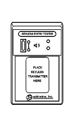
22 Pulses the horn for 30 seconds or until one of the following conditions is met: The panic button is pressed again. The ignition switch is turned to the RUN position with a valid key. The vehicle is unlocked with the key. Keyless Entry Personalization The exterior lamps and the horn chirp may be personalized as part of the remote activation verification feature. The headlamps may be personalized as part of the keyless entry alarm feature. For mode descriptions and programming instructions, refer to Driver Personalization in Personalization. Rolling Code The keyless entry system uses rolling code technology. Rolling code technology prevents anyone from recording the message sent from the transmitter and using the message in order to gain entry to the vehicle. The term "rolling code" refers to the way that the keyless entry system sends and receives the signals. The transmitter sends the signal in a different order each time. The transmitter and the RCDLR are synchronized to the appropriate order. If a programmed transmitter sends a signal that is not in the order that the RCDLR expects, then the keyless entry system will not function. Transmitter Resynchronization If the functions on the remote keyless entry transmitter do not work, or, if only the remote alarm works, after the battery is replaced, then the transmitter needs to be resynchronized to the receiver. Do this by pressing and holding the LOCK and UNLOCK buttons on the transmitter at the same time for about eight seconds. To verify that the transmitter has been resynchronized, the horn will sound and the exterior lamps will flash once. SPECIAL TOOLS AND EQUIPMENT SPECIAL TOOLS Special Tools Illustration Tool Number/ Description J Keyless Entry Tester
23
2001 Chevrolet Corvette ACCESSORIES & EQUIPMENT Remote Keyless Entry Systems - Corvette
 DESCRIPTION 2001 ACCESSORIES & EQUIPMENT Remote Keyless Entry Systems - Corvette Remote Keyless Entry (RKE) system is controlled by Remote Function Actuation (RFA) system. Transmitter allows remote control
SCHEMATIC AND ROUTING DIAGRAMS
 2004 ACCESSORIES & EQUIPMENT Tire Pressure Monitoring - Corvette SCHEMATIC AND ROUTING DIAGRAMS TIRE PRESSURE MONITORING SYSTEM SCHEMATICS Fig. 1: Tire Pressure Monitoring System Schematics Courtesy of
SCHEMATIC AND ROUTING DIAGRAMS
 2004 ACCESSORIES & EQUIPMENT Theft Deterrent - Corvette SCHEMATIC AND ROUTING DIAGRAMS THEFT DETERRENT SYSTEM SCHEMATICS Fig. 1: Theft Deterrent Relay, Security Indicator, Lighting and Horn References
KEYLESS ENTRY SYSTEM & TIRE PRESSURE MONITOR ACCESSORIES & EQUIPMENT General Motors Corp. - Remote Keyless Entry System
 KEYLESS ENTRY SYSTEM & TIRE PRESSURE MONITOR 1998 ACCESSORIES & EQUIPMENT General Motors Corp. - Remote Keyless Entry System DESCRIPTION Remote Keyless Entry (RKE) system is controlled by Remote Function
2007 Chevrolet Corvette STEERING Steering Wheel and Column - Corvette. Steering Wheel and Column - Corvette
 2007 STEERING Steering Wheel and Column - Corvette SPECIFICATIONS FASTENER TIGHTENING SPECIFICATIONS Fastener Tightening Specifications Specification Application Metric English Actuator Retaining Screws
 Page 1 of 11 2009 Hummer H2 6.2L Eng 1Search Print Date: SHIFT LOCK CONTROL SYSTEM Repair Instructions Automatic Transmission Shift Lock Control Actuator Replacement Removal Procedure NOTE: After assembling
DESCRIPTION & OPERATION
 ANTI-THEFT SYSTEM 1998 ACCESSORIES & EQUIPMENT General Motors Corp. - Anti-Theft System DESCRIPTION & OPERATION WARNING: Deactivate air bag system before performing any service operation. See AIR BAG RESTRAINT
2004 SUSPENSION. Electronic Suspension Control (ESC) - Corvette. Fastener Tightening Specifications Specification Application
 - Corvette. Fastener Tightening Specifications Specification Application") 2004 SUSPENSION Electronic Suspension Control (ESC) Corvette SPECIFICATIONS FASTENER TIGHTENING SPECIFICATIONS Fastener Tightening Specifications Specification Application Metric English Front Position
2004 SUSPENSION Electronic Suspension Control (ESC) Corvette SPECIFICATIONS FASTENER TIGHTENING SPECIFICATIONS Fastener Tightening Specifications Specification Application Metric English Front Position
DIAGNOSIS AND TESTING
 501-14-1 Handles, Locks, Latches and Entry Systems 501-14-1 DIAGNOSIS AND TESTING Locks, Latches and Entry Systems Refer to Wiring Diagrams Cell 117 for schematic and connector information. Special Tool(s)
2002 Dodge Intrepid ES ACCESSORIES & EQUIPMENT Anti-Theft Systems - Concorde, Intrepid & 300M
 DESCRIPTION SENTRY KEY IMMOBILIZER SYSTEM 2002-03 ACCESSORIES & EQUIPMENT Anti-Theft Systems - Concorde, Intrepid & 300M CAUTION: Large metallic objects, or items such as magnetic pass-keys, may cause
SCHEMATIC AND ROUTING DIAGRAMS
 2004 ACCESSORIES & EQUIPMENT Cruise Control - Corvette SCHEMATIC AND ROUTING DIAGRAMS CRUISE CONTROL SCHEMATICS Fig. 1: Cruise Control Switch, Throttle Actuator Control Motor And Cruise Control Release
2-Way Remote Start and Door Lock Transmitter Package Installation (AP3)
") Document ID: 2197450 http://gsi.xw.gm.com/si/showdoc.do?docsyskey=2197450&pubcellsyskey=176302&pu... Page 1 of 5 11/12/2009 Accessories Document ID: 2197450 2-Way Remote Start and Door Lock Transmitter
Document ID: 2197450 http://gsi.xw.gm.com/si/showdoc.do?docsyskey=2197450&pubcellsyskey=176302&pu... Page 1 of 5 11/12/2009 Accessories Document ID: 2197450 2-Way Remote Start and Door Lock Transmitter
Body Control System Circuit Description
 1999 Pontiac Montana Ext. Body Control System Circuit Description This vehicle is equipped with a body control module (BCM). The BCM performs multiple body control functions. The following vehicle systems
2001 Dodge Durango ACCESSORIES & EQUIPMENT' 'Anti-Theft Systems - Dakota & Durango 2001 ACCESSORIES & EQUIPMENT
 DESCRIPTION VEHICLE THEFT SECURITY SYSTEM 2001 ACCESSORIES & EQUIPMENT Anti-Theft Systems - Dakota & Durango Vehicle Theft Security System (VTSS) provides perimeter protection against unauthorized use
LH POWER LOCK SYSTEMS 8P - 1 POWER LOCK SYSTEMS TABLE OF CONTENTS POWER DOOR LOCKS... 1 REMOTE KEYLESS ENTRY... 4 POWER DOOR LOCKS TABLE OF CONTENTS
 LH POWER LOCK SYSTEMS 8P - 1 POWER LOCK SYSTEMS TABLE OF CONTENTS POWER DOOR LOCKS... 1 REMOTE KEYLESS ENTRY... 4 POWER DOOR LOCKS TABLE OF CONTENTS AND POWER DOOR LOCK SYSTEM...1 CENTRAL LOCKING SYSTEM...2
POWER LOCK SYSTEMS 8P - 1 POWER LOCK SYSTEMS TABLE OF CONTENTS
 AN POWER LOCK SYSTEMS 8P - 1 POWER LOCK SYSTEMS TABLE OF CONTENTS page GENERAL INFORMATION INTRODUCTION...1 POWER LOCK SYSTEM...1 REMOTE KEYLESS ENTRY SYSTEM...1 DESCRIPTION AND OPERATION CENTRAL TIMER
2010 Flex Workshop Manual. REMOVAL AND INSTALLATION Procedure revision date: 12/10/2010
 SECTION 501-12: Instrument Panel and Console REMOVAL AND INSTALLATION Procedure revision date: 12/10/2010 Refrigerator Rear console Item Part Number Description 1 04567 Front finish panel 2 045A90B Bottom
VEHICLE THEFT/SECURITY SYSTEMS
 WJ VEHICLE THEFT/SECURITY SYSTEMS 8Q - 1 VEHICLE THEFT/SECURITY SYSTEMS CONTENTS... 6 VEHICLE THEFT SECURITY SYSTEM... 1 VEHICLE THEFT SECURITY SYSTEM INDEX AND DOOR AJAR SWITCH... 3 DRIVER CYLINDER LOCK
DESCRIPTION & OPERATION
 DESCRIPTION & OPERATION 1998-99 SUSPENSION Electronic - Real Time Damping - Corvette The Real Time Damping (RTD) system automatically controls vehicle ride by independently controlling a damper solenoid
SECTION Handles, Locks, Latches and Entry Systems
 501-14-i Handles, Locks, Latches and Entry Systems 501-14-i SECTION 501-14 Handles, Locks, Latches and Entry Systems CONTENTS PAGE DIAGNOSIS AND TESTING Handles, Locks, Latches and Entry Systems... 501-14-2
POWER DOOR LOCKS 8P - 1 POWER DOOR LOCKS
 NS/GS POWER DOOR LOCKS 8P - 1 POWER DOOR LOCKS CONTENTS POWER DOOR LOCKS... 1 REMOTE KEYLESS ENTRY... 5 POWER DOOR LOCKS INDEX GENERAL INFORMATION INTRODUCTION... 1 AUTOMATIC DOOR LOCK FEATURE... 1 DOOR
2008 F-Super Duty Workshop Manual
 Page 1 of 22 SECTION 501-14: Handles, Locks, Latches and Entry Systems 2008 F-Super Duty 250-550 Workshop Manual DIAGNOSIS AND TESTING Procedure revision date: 10/14/2009 Locks, Latches and Entry Systems
Power Sliding Door (PSD) Diagnostic Approach. Fixing Intermittent Malfunctions. Power Sliding Door (PSD) Diagnostic Information
 Diagnostic Approach. Fixing Intermittent Malfunctions. Power Sliding Door (PSD) Diagnostic Information") Power Sliding Door (PSD) Diagnostic Information Power Sliding Door (PSD) The power sliding door (PSD) provides built-in diagnostics. This assists the service technicians during troubleshooting. The PSD
Power Sliding Door (PSD) Diagnostic Information Power Sliding Door (PSD) The power sliding door (PSD) provides built-in diagnostics. This assists the service technicians during troubleshooting. The PSD
Document ID# Buick LeSabre
 http://127.0.0.1:9001/servlets/blobshtml?shtmlfile=633088&evc=sm&pubid=262&cellid... Page 1 of 3 Document ID# 633088 DTC C1214 Circuit Description The system relay is energized when the ignition is ON.
 Page 1 of 6 2006 Dodge Dakota 4.7L Eng VIN J 1Search Print Date: FRONT CONTROL MODULE (FCM) MODULE-FRONT CONTROL DESCRIPTION Fig 1: IPM Wiring Connectors Courtesy of DAIMLERCHRYSLER CORP. The Front Control
2001 Chevrolet Corvette ACCESSORIES & EQUIPMENT Cruise Control Systems - Corvette
 2001 ACCESSORIES & EQUIPMENT Cruise Control Systems - Corvette DESCRIPTION Cruise control is a speed control system that maintains a desired vehicle speed under normal driving conditions. Steep grades
DTC U : Lost Communication With Anti-Lock Brake System (ABS) Control Module
 Control Module") Page 1 of 6 DTC U0100-U0299 Diagnostic Instructions 2008 Pontiac G8 G8 Service Manual Document ID: 1874258 Perform the Diagnostic System Check - Vehicle prior to using this diagnostic procedure. Review
Page 1 of 6 DTC U0100-U0299 Diagnostic Instructions 2008 Pontiac G8 G8 Service Manual Document ID: 1874258 Perform the Diagnostic System Check - Vehicle prior to using this diagnostic procedure. Review
SECTION Interior Lighting
 417-02-i Interior Lighting 417-02-i SECTION 417-02 Interior Lighting CONTENTS PAGE DIAGNOSIS AND TESTING Interior Lighting... 417-02-2 Principles of Operation... 417-02-2 Inspection and Verification...
Programmable Modes To reset or customize the features, first enter the vehicle customization main menu. To enter the main menu, do the following:
 2003 Impala Some of the convenience features can be reset or customized to perform according to Report a problem with this article your preference. Features you can program depend upon the options that
VEHICLE THEFT/SECURITY SYSTEMS
 ZG VEHICLE THEFT/SECURITY SYSTEMS 8Q - 1 VEHICLE THEFT/SECURITY SYSTEMS CONTENTS page GENERAL INFORMATION ARMING... 1 DISARMING... 2 INTRODUCTION... 1 POWER-UP MODE... 2 TAMPER ALERT... 2 DESCRIPTION AND
DOOR & LOCK SECTION DLK CONTENTS BODY EXTERIOR, DOORS, ROOF & VEHICLE SECURITY DLK-1 BASIC INSPECTION... 6 FUNCTION DIAGNOSIS...10
 BODY EXTERIOR, DOORS, ROOF & VEICLE SECURITY SECTION DLK A DOOR & LOCK B C D CONTENTS E BASIC INSPECTION... 6 DIAGNOSIS AND REPAIR WORKFLOW... 6 Work Flow...6 INSPECTION AND ADJUSTMENT... 9 ADDITIONAL
2007 Hummer H RESTRAINTS Supplemental Inflatable Restraints - H3. Supplemental Inflatable Restraints - H3
 2007 RESTRAINTS Supplemental Inflatable Restraints - H3 SPECIFICATIONS FASTENER TIGHTENING SPECIFICATIONS Fastener Tightening Specifications Specification Application Metric English Inflatable Restraint
2004 HVAC. HVAC Systems - Automatic - Corvette. Fastener Tightening Specifications Specification Application
 2004 HVAC HVAC Systems Automatic Corvette SPECIFICATIONS FASTENER TIGHTENING SPECIFICATIONS Fastener Tightening Specifications Specification Application Metric English Blower Motor Control Module Retaining
POWER DOOR LOCKS 8P - 1 POWER DOOR LOCKS CONTENTS
 PL POWER DOOR LOCKS 8P - 1 POWER DOOR LOCKS CONTENTS POWER DOOR LOCKS... 1 REMOTE KEYLESS ENTRY... 3 POWER DOOR LOCKS INDEX INTRODUCTION... 1 DOOR LOCK MOTOR... 1 DOOR LOCK SWITCH... 1 INTRODUCTION All
" MANUALLY OVERRIDING YOUR SYSTEM
 Model PRO 2000aS Owner s Manual 3 Button Remote Security System with Keyless Entry IMPORTANT! In order to provide the highest possible level of security to your vehicle, this system is equipped with selectable
Technical Bulletin AA 304. Central Locking System. m.y. 97
 Technical Bulletin Subject: Model(s): Central Locking System Cabriolet m.y. 97 Group: Number: Date: 01 96 11 Nov. 29, 1996 The following Repair Manual pages are new and will be integrated with the next
Scan Tool Does Not Communicate with Class 2 Device (W/O Immobilizer)
") Page 1 of 5 2002 GMC Truck Envoy - 4WD Bravada, Envoy, TrailBlazer (VIN S/T) Service Manual Body and Accessories Data Link Communications Diagnostic Information and Procedures Document ID: 754548 Scan
Page 1 of 5 2002 GMC Truck Envoy - 4WD Bravada, Envoy, TrailBlazer (VIN S/T) Service Manual Body and Accessories Data Link Communications Diagnostic Information and Procedures Document ID: 754548 Scan
POWER MIRROR SYSTEMS
 ZJ POWER MIRROR SYSTEMS 8T - 1 POWER MIRROR SYSTEMS CONTENTS AUTOMATIC DAY/NIGHT MIRROR... 6 OUTSIDE POWER MIRRORS... 1 OUTSIDE POWER MIRRORS INDEX GENERAL INFORMATION INTRODUCTION... 1 MEMORY SYSTEM...
BODY ELECTRICAL SYSTEM
 BODY ELECTRICAL SYSTEM 8-1 SECTION 8 BODY ELECTRICAL SYSTEM WARNING: For vehicles equipped with Supplemental Restraint (Air Bag) System: Service on and around the air bag system components or wiring must
DESCRIPTION & OPERATION
 DESCRIPTION & OPERATION 1991-92 ACCESSORIES & EQUIPMENT Anti-Theft System - Cherokee Passive anti-theft system is designed to prevent vehicle theft. The Security Alarm Module (SAM) is a logic controlled
2004 BRAKES. Antilock Brake System - Corvette
 2004 BRAKES Antilock Brake System Corvette SPECIFICATIONS FASTENER TIGHTENING SPECIFICATIONS Fastener Tightening Specifications Specification Application Metric English BPMV Brake Pipe Fittings 16 N.m
DIAGNOSIS AND TESTING
 204-04-1 Wheels and Tires 204-04-1 DIAGNOSIS AND TESTING Tire Pressure Monitoring System Special Tool(s) Vehicle Communication Module (VCM) and Integrated Diagnostic System (IDS) software with appropriate
Document ID# Chevrolet Chevy Suburban - 4WD
 Page 1 of 8 Document ID# 757392 2003 Chevrolet Chevy Suburban - 4WD Print DTC C0455 Circuit Description The steering wheel position sensor (SWPS) provides one analog signal and 3 digital
Owner's Manual. Remote Security and Convenience System INS0866 8/98
 Remote Security and Convenience System Owner's Manual IMPORTANT NOTE: The operation of the SURESTART as described in this manual is applicable to most vehicles. However, due to the engine type and configuration
TIRE PRESSURE AND MONITORING SYSTEMS (DIAGNOSTICS)
") TIRE PRESSURE AND MONITORING SYSTEMS (DIAGNOSTICS) Basic Diagnostic Procedure 1. Basic Diagnostic Procedure A: PROCEDURE CAUTION: Remove foreign matter (dust, water, oil etc.) from the tire pressure monitoring
TIRE PRESSURE AND MONITORING SYSTEMS (DIAGNOSTICS) Basic Diagnostic Procedure 1. Basic Diagnostic Procedure A: PROCEDURE CAUTION: Remove foreign matter (dust, water, oil etc.) from the tire pressure monitoring
DTC P0341 Camshaft Position (CMP) Sensor Performance
 Sensor Performance") Page 1 of 5 1999 Buick Century Century, Regal VIN W Service Manual Document ID: 345654 DTC P0341 Camshaft Position (CMP) Sensor Performance Circuit Description During cranking, the Ignition Control Module
Page 1 of 5 1999 Buick Century Century, Regal VIN W Service Manual Document ID: 345654 DTC P0341 Camshaft Position (CMP) Sensor Performance Circuit Description During cranking, the Ignition Control Module
SECTION Multifunction Electronic Modules
 419-10-i Multifunction Electronic Modules 419-10-i SECTION 419-10 Multifunction Electronic Modules CONTENTS PAGE DIAGNOSIS AND TESTING Smart Junction Box (SJB)... 419-10-2 Principles of Operation... 419-10-2
Ignition Switch [ COMPONENT TESTING ]
![Ignition Switch [ COMPONENT TESTING ]](/thumbs/86/93194209.jpg "Ignition Switch [ COMPONENT TESTING ]") Page 1 of 25 2014 Ford Fusion 2.0L Eng SE Hybrid 1Search Print Date: START BUTTON Ignition Switch [ COMPONENT TESTING ] Schematic Fig 1: Ignition Switch Schematic Courtesy of FORD MOTOR CO. Page 2 of 25
Page 1 of 25 2014 Ford Fusion 2.0L Eng SE Hybrid 1Search Print Date: START BUTTON Ignition Switch [ COMPONENT TESTING ] Schematic Fig 1: Ignition Switch Schematic Courtesy of FORD MOTOR CO. Page 2 of 25
C5 Computer Diagnostic Codes
 C5 Computer Diagnostic Codes The ability to view engine operating data such as oil pressure and coolant temperature, in digital form on the instrument panel has been a feature of Corvettes since 1984.
Model PRO 9649 Owner s Manual
 Model PRO 9649 Owner s Manual 3 Button Remote Security System with Starter Disable, & Keyless Entry IMPORTANT! In order to provide the highest possible level of security to your vehicle, this system is
DTC P1223, P1226, P1229, P1232, P1235, P1238, P1241, or P1244
 Page 1 of 5 005 Chevrolet Kodiak C-Series (Conventional) C/C5 Kodiak, TopKick C-Series Service Manual Document ID: 16600 DTC P13, P16, P1, P13, P135, P138, P11, or P1 Circuit Description The engine control
 Page 1 of 6 1Search Print Date: B3140 Power Door Lock Switch Malfunction - DTC B3140, B3145, B3150, Or B3155 Diagnostic Instructions Perform the Diagnostic System Check - Vehicle prior to using this diagnostic
SUPPLEMENTAL RESTRAINTS SYSTEM
 SECTION 8B SUPPLEMENTAL RESTRAINTS SYSTEM CAUTION: Disconnect the negative battery cable before removing or installing any electrical unit or when a tool or equipment could easily come in contact with
KEYLESS OPERATION SYSTEM (KOS)
") 42B-1 GROUP 42B KEYLESS OPERATION SYSTEM (KOS) CONTENTS GENERAL INFORMATION 42B-2 SPECIAL TOOLS 42B-8 42B-9 STANDARD FLOW OF DIAGNOSTIC TROUBLESHOOTING 42B-9 DIAGNOSTIC FUNCTION 42B-9 ID CODES REGISTRATION
42B-1 GROUP 42B KEYLESS OPERATION SYSTEM (KOS) CONTENTS GENERAL INFORMATION 42B-2 SPECIAL TOOLS 42B-8 42B-9 STANDARD FLOW OF DIAGNOSTIC TROUBLESHOOTING 42B-9 DIAGNOSTIC FUNCTION 42B-9 ID CODES REGISTRATION
Model PRO 9233N OWNER S MANUAL
 Model PRO 9233N OWNER S MANUAL KEYLESS ENTRY ALARM UPGRADE MODULE Congratulations on your purchase of this automotive Keyless Entry Upgrade Alarm System. This system is a state - of - the - art auto security
SPECIFICATIONS FASTENER TIGHTENING SPECIFICATIONS
 C6 Corvette Accessories & Equipment Mirrors - Corvette SPECIFICATIONS FASTENER TIGHTENING SPECIFICATIONS Application Metric English Inside Rearview Mirror Screw 1.5N.m 13 lb in Side Window Filler Panel
8N - 2 POWER LOCK SYSTEM
 8N - 2 POWER LOCK SYSTEM XJ POWER LOCK SYSTEM (Continued) Refer to the owner s manual in the vehicle glove box for more information on the features, use and operation of the power lock system. Fig. 1 Door
DIAGNOSIS AND TESTING
 413-09-1 Warning Devices 413-09-1 DIAGNOSIS AND TESTING Gauges And Warning Devices Refer to Wiring Diagrams Cell 59 for schematic and connector information. Refer to Wiring Diagrams Cell 60 for schematic
SECTION Rear View Mirrors
 501-09-i Rear View Mirrors 501-09-i SECTION 501-09 Rear View Mirrors CONTENTS PAGE DIAGNOSIS AND TESTING Rear View Mirrors Exterior... 501-09-2 Principles of Operation... 501-09-2 Inspection and Verification...
VEHICLE THEFT/SECURITY SYSTEMS
 TJ VEHICLE THEFT/SECURITY SYSTEMS 8Q - 1 VEHICLE THEFT/SECURITY SYSTEMS CONTENTS page GENERAL INFORMATION INTRODUCTION... 1... 1 DESCRIPTION AND OPERATION SENTRY KEY IMMOBILIZER MODULE... 1 INDICATOR LAMP...
DTC P1518 Throttle Actuator Control (TAC) Module Serial Data Circuit
 Module Serial Data Circuit") Page 1 of 6 DTC P1518 Throttle Actuator Control (TAC) Module Serial Data Circuit Circuit Description The throttle acuator control (TAC) module and the powertrain control module (PCM) communicate via a
Page 1 of 6 DTC P1518 Throttle Actuator Control (TAC) Module Serial Data Circuit Circuit Description The throttle acuator control (TAC) module and the powertrain control module (PCM) communicate via a
INTRODUCTION PRELIMINARY DIAGNOSIS
 NO: 21-11-98 SUBJECT: Transmission Simulator Diagnostic Tool DATE: Dec. 11, 1998 NOTE: THIS INFORMATION APPLIES TO VEHICLES EQUIPPED WITH A 45RFE TRANSMISSION. DISCUSSION: A new transmission simulator
DIAGNOSIS AND TESTING
 204-04-1 Wheels and Tires 204-04-1 DIAGNOSIS AND TESTING Tire Pressure Monitoring System Special Tool(s) Principles of Operation Activation Tool, Tire Pressure Monitor 204-363 Digital Tire Gauge 204-354
Keyless Go (KG) 218 HO Keyless Go (GC_JL_JM)
 218 HO Keyless Go (GC_JL_JM)") Keyless Go (KG) 218 HO Keyless Go (GC_JL_JM) 04-05-02 1 These technical training materials are current as of the date noted on the materials, and may be revised or updated without notice. Always check
Keyless Go (KG) 218 HO Keyless Go (GC_JL_JM) 04-05-02 1 These technical training materials are current as of the date noted on the materials, and may be revised or updated without notice. Always check
CHR-2. Relearn can be completed using a properly formatted scan tool and relearn magnet. * Relearn magnet not required for Prowler CHR-4
 CHR-1 1. Inflate all tires pressure to listed on tire placard 2. Turn the ignition switch to the ON position (engine off) displayed. 4. Press the STEP button to select YES. 5. Press the MENU button to
NOTE: The Smart Junction Box (SJB) is also known as the Generic Electronic Module (GEM).
 is also known as the Generic Electronic Module (GEM).") SECTION 417-01: Exterior Lighting 2009 Mustang Workshop Manual DIAGNOSIS AND TESTING Procedure revision date: 05/23/2008 Reversing Lamps Special Tool(s) 73III Automotive Meter 105-R0057 or equivalent Vehicle
SECTION 417-01: Exterior Lighting 2009 Mustang Workshop Manual DIAGNOSIS AND TESTING Procedure revision date: 05/23/2008 Reversing Lamps Special Tool(s) 73III Automotive Meter 105-R0057 or equivalent Vehicle
Document ID: General Motors Corporation. All rights reserved.
 Page 1 of 6 2005 Chevrolet TrailBlazer - 4WD Envoy, Rainier, TrailBlazer, Ascender (VIN S/T) Service Manual Document ID: 1489377 DTC P0053 or P0054 Circuit Description The heated oxygen sensor (HO2S) must
Ultrasonic interior monitoring On Board Diagnostic (OBD)
") Page 1 of 44 01-108 Ultrasonic interior monitoring On Board Diagnostic (OBD) General Information The ultrasonic interior monitoring system is only offered in conjunction with the anti-theft system. The
Page 1 of 44 01-108 Ultrasonic interior monitoring On Board Diagnostic (OBD) General Information The ultrasonic interior monitoring system is only offered in conjunction with the anti-theft system. The
DESCRIPTION & OPERATION
 DESCRIPTION & OPERATION 2001 ACCESSORIES/SAFETY EQUIPMENT General Motors Corp. - Air Bag Restraint Systems WARNING: Accidental air bag deployment is possible. Personal injury may result. To avoid injury
G - TESTS W/CODES - 2.2L
 G - TESTS W/CODES - 2.2L 1994 Toyota Celica 1994 ENGINE PERFORMANCE Toyota 2.2L Self-Diagnostics Celica INTRODUCTION If no faults were found while performing F - BASIC TESTING, proceed with self-diagnostics.
1999 Toyota RAV ACCESSORIES & EQUIPMENT Cruise Control Systems - RAV4
 1999 ACCESSORIES & EQUIPMENT Cruise Control Systems - RAV4 DESCRIPTION WARNING: Deactivate air bag system before performing any service operation. See AIR BAG RESTRAINT SYSTEMS article. DO NOT apply electrical
2007 Hummer H BRAKES Hydraulic Brakes - H3. Fastener Tightening Specifications Specification Application
 2007 BRAKES Hydraulic Brakes - H3 SPECIFICATIONS FASTENER TIGHTENING SPECIFICATIONS Fastener Tightening Specifications Specification Application Metric English Brake Hose to Caliper Bolt, Front 40 N.m
Model AX-510 Owner s Manual
 Model AX-510 Owner s Manual 4 Button Remote Security System with Dual Stage Shock Sensor IMPORTANT! In order to provide the highest possible level of security to your vehicle, this system is equipped with
Active Grille Air Shutter 1 Malfunction
 Page 1 of 5 Active Grille Air Shutter 1 Malfunction 2015 Cadillac ATS 2.0L Eng Premium Print Date: Diagnostic Instructions Perform the Diagnostic System Check - Vehicle prior to using this diagnostic procedure.
DIAGNOSTIC INFORMATION AND PROCEDURES > TRANSFER CASE SHIFT CONTROL SWITCH INOPERATIVE > CIRCUIT DESCRIPTION
 Page 1 of 9 Service Manual: TRANSFER CASE - BW 4484 DIAGNOSTIC INFORMATION AND PROCEDURES > TRANSFER CASE SHIFT CONTROL SWITCH INOPERATIVE > CIRCUIT DESCRIPTION The range/mode switch circuit consists of
Alternative Fuel Engine Control Unit
 1999 Chevrolet/Geo Cavalier (CNG) Alternative Fuel Engine Control Unit Table 1: AF ECU Function Parameters The (AF ECU) controls alternative fuel engine operation. The control unit monitors various engine
VEHICLE THEFT/SECURITY SYSTEMS
 XJ VEHICLE THEFT/SECURITY SYSTEMS 8Q - 1 VEHICLE THEFT/SECURITY SYSTEMS TABLE OF CONTENTS page GENERAL INFORMATION INTRODUCTION...1...1 DESCRIPTION AND OPERATION SENTRY KEY IMMOBILIZER MODULE....1 SENTRY
THEFT DETERRENT SYSTEM
 THEFT DETERRENT THEFT DETERRENT SYSTEM 1 System Name Power Window Control System THEFT DETERRENT SYSTEM PRECAUTION NOTICE: For initialization: When disconnecting the cable from the negative (-) battery
VEHICLE THEFT/SECURITY SYSTEMS
 TJ VEHICLE THEFT/SECURITY SYSTEMS 8Q - 1 VEHICLE THEFT/SECURITY SYSTEMS CONTENTS page GENERAL INFORMATION INTRODUCTION... 1... 1 DESCRIPTION AND OPERATION SMART KEY IMMOBILIZER MODULE... 1 INDICATOR LAMP...
HVAC Compressor Clutch Does Not Engage
 Page 1 of 6 2004 Pontiac GTO GTO (VIN V) Service Manual HVAC HVAC Systems - Manual Diagnostic Information and Procedures Document ID: 1378425 HVAC Compressor Clutch Does Not Engage Test Description The
Model: APS-610a Owner s Manual 4 Button Remote Security System with Dual Stage Shock Sensor
 Model: APS-610a Owner s Manual 4 Button Remote Security System with Dual Stage Shock Sensor IMPORTANT! In order to provide the highest possible level of security to your vehicle, this system is equipped
WIRELESS CONTROL MODULE (WCM)
") 42C-1 GROUP 42C WIRELESS CONTROL MODULE (WCM) CONTENTS GENERAL INFORMATION 42C-2 42C-5 KEYLESS ENTRY FUNCTION 42C-5 IMMOBILIZER FUNCTION 42C-9 TIRE PRESSURE MONITORING SYSTEM (TPMS) FUNCTION 42C-10 WARNINGS/ALARMS
42C-1 GROUP 42C WIRELESS CONTROL MODULE (WCM) CONTENTS GENERAL INFORMATION 42C-2 42C-5 KEYLESS ENTRY FUNCTION 42C-5 IMMOBILIZER FUNCTION 42C-9 TIRE PRESSURE MONITORING SYSTEM (TPMS) FUNCTION 42C-10 WARNINGS/ALARMS
DTC P1431 Fuel Level Sensor 2 Performance
 Page 1 of 8 Document ID# 610929 2000 Chevrolet Corvette Feedback Print DTC P1431 Fuel Level Sensor 2 Performance Circuit Description The right fuel level sensor 2, mounted in the rear
Pressing and holding the + RES switch, when the Cruise Control System is engaged, will allow the vehicle to
 CRUISE CONTROL DESCRIPTION AN... CRUISE CONTROL DESCRIPTION AND OPERATION (CRUISE CONTROL) Document ID# 2088041 Cruise Control Description and Operation Cruise control is a speed control system that maintains
Model CSI-300 Owner s Manual
 Model CSI-300 Owner s Manual 4 Button Remote Security System with Dual Stage Shock Sensor IMPORTANT! In order to provide the highest possible level of security to your vehicle, this system is equipped
Turn Signal Lamps and/or Indicators Malfunction
 Page 1 of 6 Home Account Contact ALLDATA Log Out Help DAN GRIMWOOD DAN GRIMWOOD00003 Select Vehicle New TSBs Technician's Reference Component Search: OK 2008 GMC Truck Acadia FWD V6-3.6L Conversion Calculator
Model PRO-9775T Owner's Manual 4 Button Remote Start Security System With Plug-In Shock Sensor & Starter Disable
 Model PRO-9775T Owner's Manual 4 Button Remote Start Security System With Plug-In Shock Sensor & Starter Disable FEATURES:! 2 Four Button Programmable RF Transmitters! Four Channel Code Learning Receiver
 Page 1 of 86 BODY CONTROL MODULE 2012 Ford Focus 2.0L Eng SEL REQUESTED INFORMATION Body Control Module (BCM) [ Removal And Installation ] Removal NOTE: Removal steps in this procedure may contain installation
No signal from the CMP sensor for 3 seconds with the PCM receiving an engine start signal.
 DTC P0340 Circuit Description The DTC P0340 Camshaft Position (CMP) Sensor Circuit diagnostic monitors the output of the CMP sensor. The CMP sensor is located in the distributor and consists of a signal
C5 Corvette IPC Diagnostic Display Mode
 C5 Corvette IPC Diagnostic Display Mode The IPC display, the 20-character, vacuum florescent screen above the steering column that says "Corvette by Chevrolet" every time you turn on the key is a powerful
SECURITY CONTROL SYSTEM
 BODY EXTERIOR, DOORS, ROOF & VEHICLE SECURITY SECTION SEC A SECURITY CONTROL SYSTEM B C D CONTENTS E BASIC INSPECTION... 3 DIAGNOSIS AND REPAIR WORKFLOW... 3 Work Flow...3 INSPECTION AND ADJUSTMENT...
1999 Mercury Cougar ACCESSORIES & EQUIPMENT' 'Passive Anti-Theft Systems - Cougar 1999 ACCESSORIES & EQUIPMENT
 DESCRIPTION 1999 ACCESSORIES & EQUIPMENT Passive Anti-Theft Systems - Cougar Passive Anti-Theft System (PATS) is available on some vehicles. The system is passive in that it does not require any activity
DTC P1515 Control Module Throttle Actuator Position Performance
 Page 1 of 6 Document ID# 317225 1999 Chevrolet/Geo Corvette Print DTC P1515 Control Module Throttle Actuator Position Performance Refer to Cell 20: TP and APP Sensors for complete circuit
Service Bulletin Immobilizer System (Type 6) (Supersedes , dated February 20, 2009; see REVISION SUMMARY) February 22, 2013
 (Supersedes , dated February 20, 2009; see REVISION SUMMARY) February 22, 2013") Service Bulletin 06-033 Applies To: 2007-09 MDX ALL 2007-12 RDX ALL February 22, 2013 Immobilizer System (Type 6) (Supersedes 06-033, dated February 20, 2009; see REVISION SUMMARY) REVISION SUMMARY This
Service Bulletin 06-033 Applies To: 2007-09 MDX ALL 2007-12 RDX ALL February 22, 2013 Immobilizer System (Type 6) (Supersedes 06-033, dated February 20, 2009; see REVISION SUMMARY) REVISION SUMMARY This
Model PRO-9675FT4 Owner's Manual
 Model PRO-9675FT4 Owner's Manual 4 Button Remote Start Security System With Plug-In Shock Sensor & Starter Disable FEATURES : w 2 Four Button Programmable RF Transmitters w Four Channel Code Learning Receiver
SECTION Instrument Cluster and Panel Illumination
 413-00-i Instrument Cluster and Panel Illumination 413-00-i SECTION 413-00 Instrument Cluster and Panel Illumination CONTENTS PAGE DIAGNOSIS AND TESTING Instrument Cluster and Panel Illumination... 413-00-2
 1 of 6 3/7/2013 9:56 AM 2002 Chevrolet TrailBlazer - 4WD Bravada, Envoy, TrailBlazer VIN S/T Service Manual DTC P1481 Circuit Description The powertrain control module (PCM) uses the cooling fan speed
C USTOMER C ONVENIENCE/PERSONALIZATION G UIDE
 C USTOMER C ONVENIENCE/PERSONALIZATION G UIDE S T S DRIVER INFORMATION Instrument Panel............1 Instrument Panel Cluster.......2 Driver Information Center......3 Head-Up Display.............4 SAFETY
Document ID# Chevrolet Corvette
 Page 1 of 6 Document ID# 610892 2000 Chevrolet Corvette Feedback Print D T C P 0 4 6 2 F u e l L e v e l S e n s o r C i r c u i t L o w V o l t a g e C i r c u i t D e s c r i p t i
e-ask electronic Access Security Keyless-entry
 e-ask electronic Access Security Keyless-entry Multiplex System Multiplex System Installation & Instructions (UM15 ~ 22272-03) Table of Contents Introduction... 1 Standard e-fob Operation and Features...