PCS GEAR SELECT MODULE USER GUIDE v4.0
|
|
|
- Oliver Gaines
- 5 years ago
- Views:
Transcription


1 PCS GEAR SELECT MODULE USER GUIDE v4.0 Ph:


2 Powertrain Control Solutions 1 Introduction 1.1 Included Components 1 - GSM Cable Motor Enclosur 1 - GSM Driver Interface Panel 1 - Wiring Harness GSM Cable Motor Enclosure (1) GSM Harness (1) GSM Driver Interface Panel (1) Additional Components: Transmission shift cable install kit. Available for most common transmissions Speedometer Adapter. Required for transmissions with a mechanical speedometer output. Available for GM and Ford Transmissions Page 1
3 2 Mounting 1. The GSM Cable Motor Enclosure should be mounted in a location where the shift cable can reach the transmission. The enclosure is sealed from the environment so it can be mounted outside the cabin such as on a frame rail. Keep the enclosure away from the exhaust or other heat sources. The template can be found at the end of this manual. A template is available at the end of this document. Specifications Cable Length: 6 Cable End Thread: #10-32 Cable Bracket Thread: 7/ The GSM Driver Interface Panel should be mounted in a location where the driver can easily reach and see the push buttons. The case is designed to be mounted behind a panel with the appropriate cutout for a flush appearance. The templates found at the end of this manual, provide the case outline and panel cutout dimensions. Templates are available at the end of this document. Specifications Mounting Holes: 4x #6-32 tapped thru or 4x #4 clearance holes Page 2


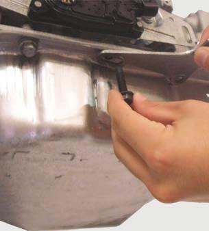
4 Powertrain Control Solutions 3 Shift Cable Shift cable installation kits are available for most common transmissions. The kits consist of a bracket and shift arm to attach the cable to the transmission. If available for your transmission, the installation kit should have been purchased with your Gear Select Module. The instructions below are based on the 4L60 installation kit. The installation procedure applies to all kits, with minor details from transmission to transmission. The specific installation kit also includes instructions for reference when installing the kit. 1. Open the plastic bag containing the parts for the cable and transmission bracket. The parts for GM transmissions are displayed in this document. There should be a cable bracket, bracket spacers, bolts, screw on cable swivel, cotter pin, and a lever arm. (Figure 1) Figure 1 2. Raise and support the vehicle in a safe and proper manner. Remove the stock selector lever, if present. The stock lever will no longer be needed. Install the provided selector lever with the stamped letters on the lever facing out. The letter F should be to the front of the vehicle (longitudinal transmission). Install the lever, torquing to 23 lb-ft. The lever should move smoothly from front to rear with positive stop in each gear position. Final position should be to the max front position. (Figure 2) Figure 2 3. Remove the two middle transmission pan bolts on the left (driver) side of the transmission. (Figure 3) Figure 3 Page 3


 Remove one locking nut and one of the two lock rings.")
 Do not tighten the nuts just yet.")
5 4. Mount the cable bracket using the two bolts provided in this kit along with the two bracket spacers between the transmission cover and the cable bracket. Torque the new pan bolts at lb-ft. Do not over tighten.(figure 4) Figure 4 5. Route the provided cable to accommodate the GSM installation and remove locking nut from the end of the cable. (Figure 5) Slip off the two rubber boots from cable. (Figure 6) Remove one locking nut and one of the two lock rings. (Figure 7) Slip the cable assembly into the cable bracket, then replace the lock ring and cable mounting nut. (Figure 8) Do not tighten the nuts just yet. Replace the rubber boots in the correct order. (Figure 9) Figure 5 Figure 6 Figure 7 Page 4


 The cable will be aligned with the shift lever during")
 Do not try to force the cable to align with")
6 Powertrain Control Solutions Figure 8 Figure 9 6. Replace the cable swivel lock nut and spin down to mid position on the threaded end. Spin on the cable swivel so that it is flush with the end of the cable. (Figure 10) The cable will be aligned with the shift lever during the shift calibration process. (Part 4: Calibrating) Do not try to force the cable to align with the shift arm. Do not attach the cable to the shift arm at this time. Figure 10 NOTE: Be sure to insert cotter pin to hold the cable swivel in place. (Figure 11) Figure 11 Page 5


 Figure 1 2.")
7 7. Snug the 7/16 cable nuts as to remove any slack towards the lever. Tighten the cable nuts. (Figure 12) Figure 12 4 Wiring 1. Connect the GSM Cable Motor Enclosure to the harness connector labeled GSM Cable Motor Enclosure. (Figure 1) Figure 1 2. Connect the GSM Driver Interface Panel to the harness. (Figure 2) Figure 2 Page 6


8 Powertrain Control Solutions 3. Verify the CAN terminator is installed into the connector labeled CAN BUS Terminator. This is a resistor that enables communication between the motor enclosure and the driver interface. This should have been installed during production. If it is not present on the harness, contact your PCS dealer. (Figure 3) Figure 3 4. If a PCS Paddle Shifter is going to be used, follow the instructions in the Paddle Shifter manual for installation and then connect the paddle shifter receiver module harness (paddle shifter quick connect harness) to the GSM Option Connector. A paddle shifter is not required for GSM operation and can be added to the vehicle at any time. (Figure 4) Figure 4 5. If a PCS transmission controller is controlling the transmission, connect the TCU s CAN connector to the connector labeled TCU CAN BUS. The transmission controller can transmit vehicle speed and brake light status to the GSM over the CAN connection and eliminate the need to hardwire these into the GSM. Verify the brake light switch is wired to the transmission controller. If the brake light switch is not wired to the transmission controller, then it either must be added to the transmission controller or it must be hard wired to the GSM as described in step 6. (Figure 5) Figure 5 Page 7


9 SKIP STEPS 6 AND 7 IF YOU PURCHASED A-GSM4020 FOR DISCRETE SHIFT INPUTS. 6. A brake switch signal is a required input to the GSM for safety. The GSM will not shift out of Park without pressing on the brake. If a PCS transmission controller was connected in step 5 and the brake light switch is wired and confirmed to be functioning to the transmission controller, then the brake switch signal does not need to be connected to the GSM. If a PCS transmission controller was not connected to the GSM in step 5, connect the brake switch signal to the brake lamp input wire. By default, the brake input is configured for a +12V signal when the brake is pressed. (Figure 6) Figure 6 7. Vehicle speed is a required input to the GSM for safety. This speed input prevents the GSM from shifting into reverse when the vehicle speed is greater than 3 MPH, and Park when the vehicle speed is greater than 1 MPH. If this connection is not made, the GSM will function but this important safety feature will be disabled. If a PCS transmission controller was connected in step 5, verify the GSM vehicle speed connector has a sealing plug in the connector to protect it from moisture and debris since it will not be used. (Figure 7) Figure 7 If your transmission has a mechanical speedometer output, a speedometer signal generator is available for GM and Ford transmissions. This signal generator plugs directly into the vehicle speed connector on the GSM harness. (Figure 8) Figure 8 Page 8


10 Powertrain Control Solutions If your transmission has an electronic speed sensor and is not controlled by a PCS TCU, then the speed signal must be shared between the stock controller and the GSM. Y cables are available from PCS for most common speed sensors to enable a plug and play connection. If a Y cable is not available, an unterminated pigtail is provided for connection into a speed signal. (Figure 9) Figure 9 8. The two wires labeled Start provide neutral safety. These two wires are connected inside the GSM when the transmission is in Park or Neutral. If your vehicle has a functioning neutral safety circuit (the vehicle will only start in Park or Neutral this could be implemented in the transmission wiring) then do not connect these wires. If your vehicle will start in any gear, these wires must be used to interrupt start circuit when in gear. Use of the GSM neutral safety is not required for the GSM to function, however it is extremely dangerous and not recommended to operate a vehicle without a neutral safety circuit. These wires must operate a relay to interrupt the start circuit. Do not connect the GSM directly to the solenoid circuit. Current greater than 0.5 Amps will damage the GSM. (Figure 10-11) Figure 10 Page 9

11 Figure The two wires labeled Backup Light are used to control reverse lights. These two wires are connected inside the GSM when the transmission is in Reverse. Use of this circuit is optional and not required for the GSM to function. To control reverse lights, connect a relay as shown in the figure below. Do not connect reverse directly through the GSM. Current greater than 0.5 Amps will damage the GSM. (Figure 12-13) Figure 12 Page 10
 11. Connect the black wire labeled Chassis Ground to a good chassis ground or directly to the negative battery terminal.")
12 Powertrain Control Solutions Figure Connect the red wire labeled Switched +12V DC to a switched ignition source capable of supplying 20 amps to the GSM. (Figure 14) 11. Connect the black wire labeled Chassis Ground to a good chassis ground or directly to the negative battery terminal. (Figure 14) Figure 14 Page 11
13 STEP 12 IS FOR DISCRETE SHIFT INPUTS (A-GSM4020) INSTALLATION ONLY. 12. To wire your GSM for discrete shift inputs, reference FIGURE 15. Figure 15 Page 12

14 5 Calibrating The GSM must be calibrated for your transmission. This procedure only has to be done once and the calibration will be stored in the GSM even when power is disconnected from the GSM. If the GSM or transmission is removed and reinstalled in the vehicle the calibration must be verified and possibly redone. The calibration procedure requires having access to the shift cable and arm at the transmission and having access to the driver interface panel. This may be easier accomplished with two people. 1. Turn power on to the GSM. When the GSM is shipped from PCS it is in programming mode and the driver interface panel will display F#1. If the display shows this, continue to Step 2. If the panel turns on but displays current gear, then a calibration has previously been performed on the GSM. To reset the calibration, press + and - simultaneously to enter the setup menu. Then press - until the display scrolls Cable Calibrate and displays 3Ca. Press D. The display will scroll Confirm Recalibration and then display No. Use the - button to change the display to Yes and press D. The display should now reset and display F#1. Continue to Step 2. If the display does not turn on, troubleshoot the wiring, including power and ground to the GSM. (Figure 1) Figure 1 2. Using the driver interface panel, set the number of transmission detents (lever positions), not including Park, Reverse, or Neutral. For example, the GM 4L60 and 4L80 have transmission detents for first, second, third, and fourth. Therefore the number 4 would be entered into the GSM. The Ford 4R70W has detents for fourth, second, and first so the number 3 would be entered even though the transmission has four gears. Use the + and - buttons until the desired number is shown and then press D. (Figure 2) Figure 2 3. If not already disconnected, disconnect the swivel and cable from the transmission shift arm. (Figure 3) Shift Arm Swivel and Cable Figure 3 Page 13


15 4. Manually move the transmission shift arm into the Park position. (Figure 4) Figure 4 5. The driver interface panel should display P. Use the + and - buttons to move the cable until the swivel is aligned with the hole in the shift arm. When properly aligned, the swivel should slide in and out of the shift arm hole. Once the swivel is aligned, press D. (Figure 5) NOTE: If the cable fails to move, press and hold N while pressing + to increase the power level to the cable. Pressing - will decrease the power level to the cable. Figure 5 6. With the swivel and cable not connected to the transmission shift arm, manually move the transmission into the next (Reverse) position. (Figure 6) Figure 6 Page 14
 Figure 7 8. With the swivel and cable not connected to the transmission shift arm, manually move the transmission into the next (Neutral) position. (Figure 8) Figure 8 9.")
16 7. The driver interface panel should display R. Use the + and - buttons to move the cable until the swivel is properly aligned with the hole in the shift arm. Once the swivel is aligned, press D. (Figure 7) Figure 7 8. With the swivel and cable not connected to the transmission shift arm, manually move the transmission into the next (Neutral) position. (Figure 8) Figure 8 9. The driver interface panel should display N. Use the + and - buttons to move the cable until the swivel is properly aligned with the hole in the shift arm. Once the swivel is aligned, press D. (Figure 9) Figure 9 Page 15
17 10. With the swivel and cable not connected to the transmission shift arm, manually move the transmission into the next (Drive) position. (Figure 10) Figure The driver interface panel should display D. Use the + and - buttons to move the cable until the swivel is properly aligned with the hole in the shift arm. Once the swivel is aligned, press D. (Figure 11) Figure Continue this process through all the lever positions. Manually move the shift arm, use the + and - buttons to align the swivel, then press D. Page 16

18 13. After saving the lowest detent position, the driver interface panel will display PIN. Insert the swivel into the transmission shift arm and use the cotter pin to secure the swivel and cable to the transmission. Keep hands clear of the shift arm and cable and press D. (Figure 13) Figure The brake light safety check is disabled in test mode so all lever positions can be quickly tested. Press each button on the driver interface panel and insure the shift cable moves the shift arm to the desired detent. The shift arm should come to rest in each detent. Please note that transmission failure can occur if the position the GSM holds the shift cable is not perfectly aligned with the transmission detents. (Figure 14) Figure If the GSM is properly calibrated and no changes need to be made, press + and - simultaneously for 3 seconds to save the calibration to the GSM. If the GSM calibration needs to be adjusted, power off and on the GSM to clear the current calibration and start over with Step 1. (Figure 15) Figure 15 Page 17
19 6 Final Verification 1. Press + and - simultaneously to enter the setup menu. The driver interface panel will scroll Setup..., 1:Backlight and then display 1BL. (Figure 1) Figure 1 2. Press and hold the N button to display the monitor screen. The monitor screen shows the brake status and the vehicle speed. When the brake is pressed, the left most segments on the driver interface panel will illuminate. Verify the brake signal functionality to the GSM. If the brake is working properly continue to the next step. If the brake signal is not working, troubleshoot the wiring before continuing. The GSM will not shift out of park without a functioning brake signal. (Figure 2-3) Brake Indicator Figure 2 (brake pedal pressed) Figure 3 (brake pedal not pressed) Page 18
20 3. Press P to exit the setup menu. The display should show the current lever position. Press R to place the transmission into reverse. Check the backup light operation if they are controlled from the GSM. If the backup lights are functioning properly or you have chosen to not control the backup lamps from the GSM, continue to the next step. If they are not functioning, troubleshoot the wiring. (Figure 4) Vehicle Speed 4. Move the vehicle to a safe, suitable location where it can be driven. It is strongly recommended that one person drives the vehicle while a different person controls and monitors the driver interface panel. Press P to place the transmission into park. Start the vehicle. While holding the brake, press D to place the transmission into drive. Enter the setup menu by pressing + and - simultaneously. Press and hold the N button to display the monitor screen. Drive the vehicle while monitoring the reported GSM vehicle speed on the monitor screen. Vehicle speed should begin to read at 1 MPH and display an accurate speed. If vehicle speed is verified to be operational, continue with the next step. If vehicle speed does not read at all, troubleshoot the wiring. If vehicle speed reads, but it is not correct, contact your dealer or PCS technical support for further assistance. (Figure 4) Figure 4 5. Move the vehicle to a safe, suitable location with ample room in front of the vehicle. With the key on, press D to place the transmission into drive. Turn the key off. With the brake pedal firmly pressed and clearance around the vehicle in case it moves forward, attempt to start the vehicle. If the vehicle does not start, verify it will start in P or N. If the vehicle only starts in P or N the neutral safety is working properly. If the vehicle does start when in drive, the neutral safety circuit must be connected as described in this manual. 7 Operation Press the button of the desired lever position to shift the transmission. The current lever position is shown on the screen and the button is backlit blue. The brake must be pressed to shift out of park, into park, and into reverse. When in drive, the + and - buttons can be pressed to manually move the shift lever through the forward gears. The + button will not move the lever into neutral, reverse, or park. The specific button for those gears must be pressed. Page 19

21 8 Menu Structure Menu Controls will either return to the top level of setup, or, when already at the top level, it will exit the setup menu will go up 1 level in a menu state or go backwards in an edit process will display the speed and brake status will enter a menu item in a menu state or go forward in an edit process will select next menu item in a menu state or increase the value in an edit process will select previous menu item in a menu state or decrease the value in an edit process Back Light (1BL) Day: Displays current value(bar graph), + increases, - decreases Night: Displays current value(bar graph), + increases, - decreases Threshold: Displays current value(bar graph), + increases, - decreases Monitor (2Mo) One screen to display speed in the user selected units (0-99, right two digits) with a block of LED s to show brake press (Illustrated Right). Calibrate Cable (3Ca) Vehicle Speed Speed (4Sp) Confirm Calibration? Yes: See GSM Calibration (p.12) No Brake Indicator: LED block only shows if brake is pressed. Source GSM Pulses per mile: Displays current value, + increases, - decreases Trigger Level: Displays current value, + increases, - decreases Filter: Displays current value, + increases, - decreases Lockout Park: Displays current value, + increases, - decreases Lockout Reverse: Displays current value, + increases, - decreases Units: Displays current value, +/- toggles value. Options are MPH or KPH. CAN CAN Format: Displays current value, +/- toggles. Options are PCS or GM Lockout Park: Displays current value, + increases, - decreases Lockout Reverse: Displays current value, + increases, - decreases Brake (5Br) Units: Displays current value, +/- toggles value. Options are MPH or KPH. Source GSM On Level: Displays current value, +/- toggles value. Options are 12 or GND Pull: Displays current value, +/- toggles value. Options are UP or DN Reverse Logic: Displays current value, +/- toggles value. Options are ON or OFF. CAN CAN Format: Displays current value, +/- toggles. Options are PCS or GM Page 20
 Manual Mode Setup (MMS) Manual Gear Count: Displays current value, +/- toggles value.")
22 Paddle/TCU (6Pa) Paddle Input: Displays current value, +/- toggles value. Options are ON or OFF. Manual Mode with TCU : Displays current value, +/- toggles value. Options are ON or OFF. *Note: Requires TCU firmware MajorVer >= 2 & Paddle Input must be set to ON. OFF ON: TCU Detected or TCU Not Detected (Continue Anyway?) Manual Mode Setup (MMS) Manual Gear Count: Displays current value, +/- toggles value. Manual Range +/- toggles GSM Gear, D moves to next commanded gear. (*Note: Please view the table below) Commanded Gear GSM Gear Commanded Gear GSM Gear This table is for example purposes only. Remember number of commanded gears is based on the set number of forward gears Input Alternatives (7In): Parallel PRND: *Note: Source for Brake & VSS must not be set to GSM Parallel PRND: +/- toggles. Options are ON or OFF OFF ON P On Level: Displays current value, +/- toggles value. Options are 12 or GND P Pull: Displays current value, +/- toggles value. Options are UP or DN P Reverse Logic: Displays current value, +/- toggles value. Options are ON or OFF P Momentary or Toggle: Display current value, +/- toggles value. Options are Tgl or Mom R On Level: Displays current value, +/- toggles value. Options are 12 or GND R Pull: Displays current value, +/- toggles value. Options are UP or DN R Reverse Logic: Displays current value, +/- toggles value. Options are ON or OFF R Momentary or Toggle: Display current value, +/- toggles value. Options are Tgl or Mom N On Level: Displays current value, +/- toggles value. Options are 12 or GND N Pull: Displays current value, +/- toggles value. Options are UP or DN N Reverse Logic: Displays current value, +/- toggles value. Options are ON or OFF N Momentary or Toggle: Display current value, +/- toggles value. Options are Tgl or Mom D On Level: Displays current value, +/- toggles value. Options are 12 or GND D Pull: Displays current value, +/- toggles value. Options are UP or DN D Reverse Logic: Displays current value, +/- toggles value. Options are ON or OFF D Momentary or Toggle: Display current value, +/- toggles value. Options are Tgl or Mom Page 21
23 View/Clear GSM Error Codes (8Er): No Errors Errors: Displays error number (ex: er#1) and the description of error No Yes: Clears error Code Scrolled Description Condition to Set Common Causes and Remedies 1 ER#1: Motor position sensor fault. Clear? 2 ER#2: Gear shift required excessive time. Clear? 3 ER#3: Shift cable position was outside of calibrated range. Clear? 4 ER#4: Button release not detected - check your input device. Clear? Internal position sensors differ by more than 0.35 inches Desired position move is not accomplished in 1 second Position sensor reading outside calibrated range Button press duration greater than 5 seconds If this code is generated, contact PCS technical support. This is most likely an indication that there is an internal fault inside the motor enclosure. PCS must perform this service. Do not attempt to open the motor enclosure. The motor is designed to quickly move the shift arm to the desired position. Several common causes of slow motor movement include: Cable routing causing a very tight bend in the cable. To solve this problem reroute the cable to minimize tight bends. Battery voltage too low resulting in not enough power at the motor. To solve this problem, confirm the battery is fully charged or charge accordingly. Also inspect the wiring to ensure proper connection points. The GSM can draw up to 20 amps so proper wire installation practices are essential. This is typically an issue with the calibration. Re-perform the calibration procedure. Check to make sure the buttons are not stuck. Press each button and ensure the button rises back up after it is pressed. If a button appears to be sticking, contact PCS technical support. Edit Cable and Motor Setup (9Ed): *Note: Cable must be disconnected from the arm to complete the options below. When adjusting detent position, pressing N will change to position sensor reading. Adjust Cable Position: Displays current gear: +/- toggles position Save new position? No Yes Calibrate Cable Length How many 1/1000 inches?: Displays current value, + increases, - decreases *Note: To determine, measure how far the cable petrudes from its sheath. LIMITED WARRANTY STATEMENT. Powertrain Control Solutions, LLC. Warrants all merchandise against defects in factory workmanship and materials for a period of 12 months after purchase. This warranty applies to the first retail purchaser and covers only those products exposed to normal use or service. Provisions of this warranty shall not apply to Powertrain Control Solutions, LLC. Product used for a purpose for which it is not designed, or which has been altered in any way that would be detrimental to the performance or life of the product, or misapplication, misuse, negligence or accident. On any part or product found to be defective after examination by Powertrain Control Solutions, LLC., Powertrain Control Solutions, LLC. will only repair or replace the merchandise through the original selling dealer or on a direct basis. Powertrain Control Solutions, LLC. assumes no responsibility for diagnosis, removal and/or installation labor, loss of vehicle use, loss of time, inconvenience or any other consequential expenses. The warranties herein are in lieu of any other expressed or implied warranties, including any implied warranty of merchantability or fitness, and any other obligation on the part of Powertrain Control Solutions, LLC., or selling dealer. Page 22
24 GSM Cable Motor Enclosure Template
25 GSM Driver Interface Panel Template
26 GSM Inline Driver Interface Panel Template
Speedo With Telltales and Display 85mm Tech Support Instruction Sheet # A2C Rev
 Gauge Installation: 1. Select the desired mounting location of the instrument. 2. Depending on your mounting situation it might be necessary to configure the gauge before installation. See page 2 - Setting
Viewline Instrument Kit Installation Instructions. Rev E. Important Installation Notes:
 Read these instructions thoroughly before installation. Do not deviate from assembly or wiring diagram. Always disconnect battery ground before making any electrical connections. IMPORTANT: Mounting dimensions
This document describes:
 Thank you for purchasing this product from ERM. We appreciate your interest in our unique product line as we try to offer our customers an alternative to today s traditional products. This programmable
Diagram D Parts of the Fuel Level Sender Unit to be Adjusted
 Fuel Level Sender Installation: The fuel sender in this kit has a resistance rating of 10 ohms when the tank is empty and 180 ohms when full. The unit can be adjusted to reqd accurately in tanks from 6-23"
DCC-3000 Climate Control for Vintage Air GEN-IV systems
 INSTALLATION AND OPERATOR S MANUAL FOR DCC-3000 Climate Control for Vintage Air GEN-IV systems PARTS INCLUDED WITH THIS SYSTEM Vent sensor housings: 2 1 / 2 housings (x2) 2 housings (x2) Installation/operator
UTV-1200 Multi Gauge for 2008 Yamaha Rhino
 IMPORTANT NOTE! This gauge has an hour meter and odometer preset option available only for the first 1.0 engine hour and 10 miles (16km). See ODO/HR PRESET for instructions. UTV-1200 Multi Gauge for 2008
This document describes:
 Thank you for purchasing this product from ERM Products. We appreciate your interest in our unique product line as we try to offer our customers an alternative to today s traditional products. This universal
MODEL MCL-3212 SPEEDOMETER/TACHOMETER for 2012 up Dyna and Softail with 4 gauge
 MODEL MCL-3212 SPEEDOMETER/TACHOMETER for 2012 up Dyna and Softail with 4 gauge IMPORTANT NOTE! This gauge has an odometer preset option that is only available one time in the first 100 miles (160km) of
MCL-30K-SPD IMPORTANT NOTE!
 MCL-30K-SPD Thank you for purchasing the Dakota Digital MCL-30K-SPD gauge for your Harley Davidson Touring bike. This is designed to be a replacement for all touring models from 1996 2003. This is part
DCC-2500 Digital Climate Control for Vintage Air GEN-IV systems
 INSTALLATION AND OPERATOR S MANUAL FOR DCC-2500 Digital Climate Control for Vintage Air GEN-IV systems PARTS INCLUDED WITH THIS SYSTEM Vent sensor housings: 2 1 / 2 housings (x2) 2 housings (x2) Installation/operator
Gauge Installation Instructions
 Gauge Installation Instructions TEMPERATURE, PRESSURE AND FUEL LEVEL GAUGES VOLTMETER RUDDER POSITION INDICATOR A. Disconnect battery. B. Cut 2-3/32" hole in a suitable position in dash. Make sure rear
MODEL MCL /8 SPEEDOMETER/TACHOMETER for 2004 up
 MODEL MCL-3204 3-3/8 SPEEDOMETER/TACHOMETER for 2004 up IMPORTANT NOTE! This gauge has an odometer preset option that is only available one time in the first 100 miles (160km) of operation. See Odometer
SELECT DIAGNOSTIC GUIDE. INST028 Doc 3.02
 SELECT DIAGNOSTIC GUIDE INST028 Doc 3.02 CONTENTS General Information...2 Select Call-Outs...3 Wire Diagram and Legend...4 Diagnostics...6 Excessive Voltage Drop Diagnostics...6 Static Diagnostics...7
Paddle Shifter User s Guide
 Paddle Shifter User s Guide Included Parts List: 1 - Receiver Module 1 - Receiver Module Harness (5 length) 1 - Paddle Shifter Module 1 - Paddle Shifter Module Harness 1 ½ Spacer 2 ¼ Spacer 1 User s Guide
REMOVAL OF FACTORY GAUGE ULTRA FLHT & FLHX (STREET GLIDE
 MCL-36K-SPD Thank you for purchasing the Dakota Digital MCL-36K-SPD gauge for your Harley Davidson Touring bike. This kit is designed to be a direct, plug in replacement for all touring models from 2004
Tachometer Installation and Operation Instructions Addendum for Dual Shift Point (DSP) Eliminator Tachometer
 Eliminator Tachometer") Tachometer Installation and Operation Instructions Addendum for Dual Shift Point (DSP) Eliminator Tachometer Siemens VDO Allentown, Pennsylvania USA THE INSTRUCTIONS FOR OPERATION AND ELECTRICAL WIRING
Tachometer Installation and Operation Instructions Addendum for Dual Shift Point (DSP) Eliminator Tachometer Siemens VDO Allentown, Pennsylvania USA THE INSTRUCTIONS FOR OPERATION AND ELECTRICAL WIRING
BIM-17-2 Bus Interface Module for compass and outside temperature
 BIM-17-2 Bus Interface Module for compass and outside temperature Mount the temperature sensor in the front grill area or another location that can get good air flow while the vehicle is being driven.
MCL-5100, 5200, & 5400 Bar mount digital speedometer with indicators.
 MCL-5100, 5200, & 5400 Bar mount digital speedometer with indicators. *To avoid damage to motorcycle, please see Speedometer and Indicators sections for details on locating VSS and indicator wires for
BEGIN HERE except CAUTION: DO NOT OVERTIGHTEN. Wiring the Voltmeter: IMPORTANT: Voltmeter Installation: CAUTION!!! Parts List
 BUb_VF_\d]UdUb
UTV-1000 Multi Gauge for Yamaha Rhino
 IMPORTANT NOTE! This gauge has an hour meter and odometer preset option available only for the first 1.0 engine hour and 10 miles (16km). See ODO/HR PRESET for instructions. UTV-1000 Multi Gauge for 2004-2006
SB SWITCH CONTROL BOX
 Carson Manufacturing Co., Inc. 5451 North Rural Street Indianapolis, IN 462 Phone: (888) 577-6877 Fax: (317) 254-2667 www.carsonsirens.com SB-008-25 SWITCH CONTROL BOX INSTALLATION AND OPERATING INSTRUCTIONS
MODEL MVX-2011 TANK MOUNT SPEEDOMETER/TACHOMETER
 MODEL MVX-2011 TANK MOUNT SPEEDOMETER/TACHOMETER Wiring Diagram The MVX-2011 gauges will work on 2011-up Softail models with 5 gauges or 2012-up Dyna models with 5 gauges. It is a direct plug in on these
ODY-19-6 DUAL, TRIPLE, or QUAD AIR PRESSURE GAUGE
 BIM-xx-2 power & data connectors. Either one can be used. TNK + TNK TNK - LR - LR LR + RR - RR RR + LF - LF LF + RF - RF RF + PWR GND DIM SW WRN ODY-19-6 DUAL, TRIPLE, or QUAD AIR PRESSURE GAUGE Warning
SST-3 Start-Stop-Throttle
 SST-3 Start-Stop-Throttle Installation & Operation Guide Revision 1.1 Internet: www.wiredrite.com E-mail: info@wiredrite.com Page 1 CONTENTS Introduction 2 Hardware Mounting 2 Connections 2 Operation &
AEROMOTIVE Part # INSTALLATION INSTRUCTIONS
 AEROMOTIVE Part # 16306 INSTALLATION INSTRUCTIONS CAUTION: Installation of this product requires detailed knowledge of automotive systems and repair procedures. We recommend that this installation be carried
Tachometer. Installation and Operation Instructions
 THE INSTRUCTIONS FOR INSTALLATION AND ELECTRICAL WIRING FOR THESE TACHOMETERS FOLLOW. USE IS RESTRICTED TO 12 VOLT NEGATIVE GROUND ELECTRICAL SYSTEMS. Parts List Item Description Quantity 1. Tachometer
ION-01-6 PERFORMANCE SPEEDOMETER/TACHOMETER COMBO
 ION-01-6 PERFORMANCE SPEEDOMETER/TACHOMETER COMBO MOUNTING: It should be inserted into the opening from the front and the L-clamps will be installed from the back. Tighten the nuts on the L-clamps so that
HLY-3015 MINI SPEED/TACH INFORMATION SYSTEM (weather and vibration resistant for exposed environments)
") HLY-3015 MINI SPEED/TACH INFORMATION SYSTEM (weather and vibration resistant for exposed environments) Neutral Left turn Low voltage Right turn High beam Engine Low oil *To avoid damage to motorcycle,
HLY-3015 MINI SPEED/TACH INFORMATION SYSTEM (weather and vibration resistant for exposed environments) Neutral Left turn Low voltage Right turn High beam Engine Low oil *To avoid damage to motorcycle,
MoistureMatch A next generation grain tester
 MoistureMatch A next generation grain tester A next generation moisture tester incorporating new and unique technology. Finally, a portable tester that will more accurately match and track with the commercial
Universal Gear Shift Sender for use with Lokar Indicators GSS-1000-LOK The easiest system to install and use on the market.
 Universal Gear Shift Sender for use with Lokar Indicators GSS-1000-LOK The easiest system to install and use on the market. GSS-1000 DECODER N.S. relay B.U. PWR Dim GND Safety Backup Power Dim Park Reverse
Installation Instructions Street Bandit Shifter
 Installation Instructions Street Bandit Shifter Part Number 80797 (see www.bmracing.com for the latest technical product information) 2006, 2000 by B&M Racing and Performance Products The B&M Street Bandit
Aftermarket Interface Module
 An ISO 9001:2008 Registered Company Aftermarket Interface Module (2015-2018 Ford Transit) AIM514-B High Side Solenoid type Coolant Valve Control AIM515-B Motor Reversing type Coolant Valve Control Introduction
HLY-3016 PERFORMANCE SPEEDOMETER/TACHOMETER COMBO (weather and vibration resistant for exposed environments)
") HLY-3016 PERFORMANCE SPEEDOMETER/TACHOMETER COMBO (weather and vibration resistant for exposed environments) *To avoid damage to motorcycle, please see Speedometer, Tachometer, and Status and Warning Indicators
HLY-3016 PERFORMANCE SPEEDOMETER/TACHOMETER COMBO (weather and vibration resistant for exposed environments) *To avoid damage to motorcycle, please see Speedometer, Tachometer, and Status and Warning Indicators
TrimSync Installation & Operating Instructions
 TrimSync Installation & Operating Instructions Mounting the Device The unit should be mounted in a dry area away from sources of heat. Mounting the unit near the trim pumps will reduce wiring complications.
AUTO-BLiP. User Manual Porsche INTELLIGENT DOWNSHIFTS. Version 1.2
 AUTO-BLiP INTELLIGENT DOWNSHIFTS www.auto-blip.com User Manual 2005+ Porsche Version 1.2 Copyright 2012 Tractive Technology, LLC. All rights reserved. Page 1 WARNING Use of the AUTO-BLiP while driving
AUTO-BLiP. User Manual Lotus INTELLIGENT DOWNSHIFTS. Version 1.0
 AUTO-BLiP INTELLIGENT DOWNSHIFTS www.auto-blip.com User Manual Lotus Version 1.0 Copyright 2012 Tractive Technology, LLC. All rights reserved. Page 1 WARNING Use of the AUTO-BLiP while driving could lead
AEROMOTIVE Part # INSTALLATION INSTRUCTIONS
 AEROMOTIVE Part # 16302 INSTALLATION INSTRUCTIONS CAUTION: Installation of this product requires detailed knowledge of automotive systems and repair procedures. We recommend that this installation be carried
Photo 1. Shift pattern gate plate
 Installation Instructions MAGNUM GRIP STREET BANDIT SHIFTER Fits: GM, Chrysler, and Ford Automatic Transmissions See Application Guide for Specific Vehicles Catalog # 81050 WORK SAFELY! For maximum safety,
AUTO-BLiP. User Manual Ford Mustang INTELLIGENT DOWNSHIFTS. Version 1.2
 AUTO-BLiP INTELLIGENT DOWNSHIFTS www.auto-blip.com User Manual 2015-2016 Ford Mustang Version 1.2 Copyright 2012 Tractive Technology, LLC. All rights reserved. Page 1 WARNING Use of the AUTO-BLiP while
Marine Products. SL-3 Engine Controls. Owner s Manual
 Marine Products SL-3 Engine Controls Owner s Manual This manual must be accessible to the owner/user of this Morse marine product. Includes installation, operation and maintenance instructions for your
Gauge Installation Instructions
 Gauge Installation Instructions TEMPERATURE, PRESSURE AND FUEL LEVEL GAUGES VOLTMETER RUDDER POSITION INDICATOR A. Disconnect battery. B. Cut 2-3/32" hole in a suitable position in dash. Make sure rear
MODEL NUMBER: MEDIUM DUTY ONBOARD AIR SYSTEM
 MODEL NUMBER: 10003 MEDIUM DUTY ONBOARD AIR SYSTEM IMPORTANT: It is essential that you and any other operator of this product read and understand the contents of this manual before installing and using
Installation Instructions Z-Gate Shifter
 Installation Instructions Z-Gate Shifter Part Number 80681 1998, 2001 by B&M Racing and Performance Products The B&M Z-Gate shifter can be used in vehicles equipped with most popular three speed automatic
ECLIPSE Laundry Dispenser Controller
 ECLIPSE Laundry Dispenser Controller Reference Manual Programming and Operation Online and downloadable Product Manuals and Quick Start Guides are available at www.hydrosystemsco.com Please check online
WARNING: DO NOT USE HAND-HELD 2-WAY TRANSCEIVERS INSIDE YOUR VEHICLE WHILE DRIVING.
 CRC-2000 Drive-by-Wire Cruise Control System Introduction You have purchased one of the finest cruise control systems on the market. The cruise control features: Enhanced Adaptability Enhanced Features
Technical Support (707)
") Installation Instructions CONSOLE MEGASHIFTER Fits: 1982-1992 Camaro & Firebird w/automatic Transmission *except 1988-1992 Firebird Formula Model Catalog # 80692 WORK SAFELY! For maximum safety, perform
Installation Instructions CONSOLE MEGASHIFTER Fits: 1982-1992 Camaro & Firebird w/automatic Transmission *except 1988-1992 Firebird Formula Model Catalog # 80692 WORK SAFELY! For maximum safety, perform
Owner s Guide APS596Z
 Owner s Guide For Models: APS596Z Security / Keyles Entry System IMPORTANT NOTE: The operation of the Security and Convenience System as described in this manual is applicable to most vehicles. However,
MCL-3000 SERIES AIR PRESSURE PART# MCL-3K-A
 MCL-3000 SERIES AIR PRESSURE PART# MCL-3K-A Thank you for purchasing the Dakota Digital MCL-3K-A gauge for your Harley Davidson Touring bike. This gauge is designed to be a direct, plug in replacement
Installation Instructions Sport Shifter
 The B&M Sport Shifter can be used in vehicles equipped with most popular three speed or four speed automatic transmissions. It is equipped with neutral safety and backup light switches, transmission brackets
DSL-1 E DIESEL TACH INTERFACE UNIT
 DSL-1 E DIESEL TACH INTERFACE UNIT This unit can provide a tachometer signal to drive a standard ignition system tachometer. The input signal can be from a tachometer output from the alternator, from a
COMMANDO REMOTE CONTROL ENGINE STARTER. Limited Warranty Statement MADE IN THE U.S.A. IMPORTANT KEEP YOUR INVOICE WITH THIS WARRANTY STATEMENT!
 Limited Warranty Statement GNU COMMANDO LINE WARRANTY STATEMENT GNU warrants this product to be free from defects in material and workmanship for a period of one (1) year from the date of sale to the original
MCL-3000 SERIES OIL TEMP PART# MCL-3K-TMP
 MCL-3000 SERIES OIL TEMP PART# MCL-3K-TMP Thank you for purchasing the Dakota Digital MCL-3K-TMP gauge for your Harley Davidson Touring bike. This gauge is designed to be a direct, plug in replacement
AUTO-BLiP. User Manual Chevrolet Corvette. Version 1.7
 AUTO-BLiP INTELLIGENT DOWNSHIFTS www.auto-blip.com User Manual 2008-2013 Chevrolet Corvette Version 1.7 Copyright 2012 Tractive Technology, LLC. All rights reserved. Page 1 WARNING Use of the AUTO-BLiP
AUTO-BLiP. User Manual Chevrolet Corvette. Version 1.2
 AUTO-BLiP INTELLIGENT DOWNSHIFTS www.auto-blip.com User Manual 1997-2004 Chevrolet Corvette Version 1.2 Copyright 2012 Tractive Technology, LLC. All rights reserved. Page 1 WARNING Use of the AUTO-BLiP
MCL-30K-TCH. Remove nuts/screws and clamp to remove factory gauges 1 MAN#650336
 MCL-30K-TCH Thank you for purchasing the Dakota Digital MCL-30K-TCH gauge for your Harley Davidson Touring bike. This kit is designed to be a replacement for all touring models, from 1996 2003. This is
Flow Chart Programming Instructions for : Transmission Temperature 2 1/16 START HERE PROGRAM MAIN MENU
 Flow Chart Programming Instructions for : Transmission Temperature 2 1/16 START HERE PROGRAM MAIN MENU (Press one button at a time) MAIN MENU ONE AT A TIME DOWN UP - + NORMAL/DIAL BRIGHTNESS: Press the
Digital Fuel Gauge P/n (With Dual Ohms Range option)
") Digital Fuel Gauge P/n 301.530 (With Dual Ohms Range option) Green Brown Red 12V 90 Ohms 180 Ohms Ignition Gauge Rear View Green 180R (Sw S_180) Brown 90R (Sw S_90) 180 Ohms 90 Ohms Front Fuel tank unit
Digital Fuel Gauge P/n 301.530 (With Dual Ohms Range option) Green Brown Red 12V 90 Ohms 180 Ohms Ignition Gauge Rear View Green 180R (Sw S_180) Brown 90R (Sw S_90) 180 Ohms 90 Ohms Front Fuel tank unit
General Information. Installation Tips. Connections
 INSTALLATION INSTRUCTIONS ELITE DIGITAL SPEEDOMETER 2650-1951-77 Models 6789-CB, 6789-PH, 6789-SC, 6789-UL QUESTIONS: If after completely reading these instructions you have questions regarding the operation
Installation Instructions Unimatic Shifter
 Installation Instructions Unimatic Shifter Universal Shifter for Automatic Transmissions Part Number 80775 2010, 2000 by B&M Racing & Performance Products The B&M Unimatic is a universal shifter that will
DYNOTUNE 2 STAGE RPM WINDOW SWITCH WITH TPS INSTALLATION INSTRUCTIONS
 DYNOTUNE 2 STAGE RPM WINDOW SWITCH WITH TPS INSTALLATION INSTRUCTIONS Introduction: READ ALL INSTRUCTIONS BEFORE STARTING! This DynoTune device will control up to two stages of nitrous oxide. They are
Series II ODYR/SLX-01-1-C PERFORMANCE SPEEDOMETER
 Series II ODYR/SLX-01-1-C PERFORMANCE SPEEDOMETER MOUNTING: The gauge requires a round hole 3-3/8 in diameter. It should be inserted into the opening from the front and the U-clamp will be installed from
Air Shift Module User Manual
 1 Air Shift Module User Manual Important leave the shift solenoid connector unplugged until you have configured the shift input polarity and verified correct operation! tech@schnitzracing.com 2 These instructions
DUAL LINEAR MOTOR / ACTUATOR CONTROLLER W/ CURRENT SENSING AUTO REVERSE
 PAC-3200 DUAL LINEAR MOTOR / ACTUATOR CONTROLLER W/ CURRENT SENSING AUTO REVERSE PAC-3200 PRESET BUTTONS MOTOR 2 DUAL LINEAR MOTOR CONTROLLER WITH SAFETY REVERSE MOTOR 2 MOTOR 1 MAIN #1 ACC DISABLE #2
REMOTE CENTRAL LOCK. Model: CLRxxx-ULT
 REMOTE CENTRAL LOCK Model: CLRxxx-ULT Contents Remote Lock, Remote Unlock, Car Finder, Remote Boot release:, Power Window outoput, Learning Transmitter Codes... page 3 Wiring Diagram... page 4 Introduction,
AIR CONTROL ACCESSORY KIT
 RAPID RESPONSE SYSTEM 2283 AIR CONTROL ACCESSORY KIT INSTALLATION INSTRUCTIONS Congratulations on your purchase of a new Air Control Accessory Kit. This kit was designed to provide inflation control of
Classic Instruments Ford. Installation Manual
 Classic Instruments 1940 Ford Installation Manual Table of Contents Welcome from the Team at Classic Instruments!... 3 Mount New Gauge Cluster... 4 Instrument Cluster Wiring... 5 Pulse Signal Generator
Installation Instructions. QuickSilver Shifter. Fits: GM, Ford, Chrysler Transmissions See Application Guide for Specific Applications Part # 80683
 Installation Instructions QuickSilver Shifter Fits: GM, Ford, Chrysler Transmissions See Application Guide for Specific Applications Part # 80683 WORK SAFELY! For maximum safety, perform this installation
Power Distribution System User s Manual. Model: PDS-100
 Power Distribution System User s Manual Model: PDS-0 Section Page Product Overview... 1 I) General Information... 2 II) Important Safety Information... 2 III) Installation... 3 A) Materials Provided...
Yukon Gear & Axle. D30, D44 & GM 8.5" Hardcore Locking Hub Installation Guide PLEASE READ COMPLETELY BEFORE INSTALLATION
 Yukon Gear & Axle D30, D44 & GM 8.5" Hardcore Locking Hub Installation Guide PLEASE READ COMPLETELY BEFORE INSTALLATION COPYRIGHT 2014 - Yukon Gear & Axle Application Guide: YHC70005 D30 & D44 30spl -
Installation Instructions Pro Bandit Shifter Fits: GM Powerglide Automatic Transmissions
 Installation Instructions Pro Bandit Shifter Fits: 1962-1973 GM Powerglide Automatic Transmissions Part # 80793 WORK SAFELY! For maximum safety, perform this installation on a clean, level surface and
Installation Instructions Right Hand Drive Megashifter
 Installation Instructions Right Hand Drive Megashifter Part Number 80685 1995, 2001, 2006, 2010 by B&M Racing & Performance Products The B&M Right Hand Drive Megashifter is designed specifically for vehicles
TCI FastGate Shifter Installation Instructions
 151 INDUSTRIAL DRIVE ASHLAND, MISSISSIPPI 38603 http://www.tciauto.com TELEPHONE: 662-224-8972 FAX LINE: 662-224-8255 E-MAIL: tech@tciauto.com TCI 616541 FastGate Shifter Installation Instructions The
MCL-3014 gauge kit. Optional Readings: Boost Pressure with MBM-09, Front or Rear Air Suspension Pressure with MBM-19
 MCL-3014 gauge kit Thank you for purchasing the Dakota Digital MCL gauge kit for your Harley Davidson Touring bike. This kit is designed to be a direct plug in replacement for all touring models from 2014
Generator Start Control Module
 Generator Start Control Module Part# GSCM-mini-o ATKINSON ELECTRONICS, INC. 14 West Vine Street Murray, Utah 84107 Contact cbdsales@atkinsonel.com for the proper hookup diagram. Please include the generator
WARNING: DO NOT USE HAND-HELD 2-WAY TRANSCEIVERS INSIDE YOUR VEHICLE WHILE DRIVING.
 CRC-1000 Drive-by-Wire Cruise Control System Introduction You have purchased one of the finest cruise control systems on the market. The cruise control features: Enhanced Adaptability Enhanced Features
Installation Instructions Unimatic Shifter
 Installation Instructions Unimatic Shifter Universal Shifter for Automatic Transmissions Part Number 80775 2000 by B&M Racing & Performance Products LLC The B&M Unimatic is a universal shifter that will
Siemens VDO Phone:
 Siemens http://sso-usa.siemensvdo.com/ Phone: 1-800-265-1818 !" # %]]! "&]] # ( ]] # (%]]!!( # ]] BUT4_d GXYdU4_d ## ($]] If you have any doubts, please contact your dealer or Instruments at 1-800-265-1818.
Hurst VMATIC3 INSTALLATION
 FORM 159 8530 07/12 Hurst VMATIC3 3-Speed & 4-Speed Automatic Shifter Catalog #3838530 2012 by Hurst Performance The Hurst Vmatic3 shifter can be used in vehicles equipped with most popular three speed
CONTROL BOX. Wiring the control box into the vehicle. +12V
 CONTROL BOX Once the display panel is in place, mount the control box within the connecting cable's distance (approximately 3 feet) and secure to the underside of the dashboard. This case does not have
INSTALLATION AND OPERATION MANUAL FOR MCH-GPS17 GPS Compass and Ambient Temperature Gauge. NUTS (x3) 1 +12V TEMP SENSOR
 1 +12V TEMP SENSOR") KIT INCLUDES: INSTALLATION AND OPERATION MANUAL FOR MCH-GPS17 GPS Compass and Ambient Temperature Gauge MCH-GPS17 GAUGE (x1) SWITCH (x1) MANUAL (x1) NUTS (x3) GAUGE FEATURES: WIRE TIES (x6) 2 3 1 +12V
KIT INCLUDES: INSTALLATION AND OPERATION MANUAL FOR MCH-GPS17 GPS Compass and Ambient Temperature Gauge MCH-GPS17 GAUGE (x1) SWITCH (x1) MANUAL (x1) NUTS (x3) GAUGE FEATURES: WIRE TIES (x6) 2 3 1 +12V
Installation Instructions Console Megashifter
 Installation Instructions Console Megashifter 1968-1969 Camaro Part Number 81035 This B&M Megashifter is designed to fit in the console of a 1968-1969 Chevrolet Camaro. In 1968, these vehicles were equipped
DMG200. Digital Micron Gauge. 99 Washington Street Melrose, MA Phone Toll Free
 DMG200 Digital Micron Gauge 99 Washington Street Melrose, MA 02176 Phone 781-665-1400 Toll Free 1-800-517-8431 Visit us at www.testequipmentdepot.com Parts Diagram 2 LCD Display Item A B C Main Numeric
MSD 7AL-3, Ignition Control PN 7230
 MSD 7AL-3, Ignition Control PN 7230 Important: Read the instructions before attempting the installation. Parts Included: 1-7AL-3, PN 7230 1 - Parts bag (wires and connectors) 4 - RPM Modules 3000, 7000,
Xtreme Air Command. Step 1 Prepare the components. Step 2 Select a mounting location. Parts list
 2549 60 90 400 600 30 200 120 800 psi 1000 kpa PSI 0 150 Xtreme Air Command Installation instructions Congratulations on your purchase of a new Xtreme Air Command kit. This kit was designed to provide
MODEL MCV-7000 series SPEEDOMETER/TACHOMETER INFORMATION GAUGE Please read this before beginning installation or wiring.
 MODEL MCV-7000 series SPEEDOMETER/TACHOMETER INFORMATION GAUGE Please read this before beginning installation or wiring. IMPORTANT NOTE! This gauge has an odometer preset option that is only available
Vehicle Programming Instructions Ford Powerstroke 7.3 liter
 Vehicle Programming Instructions 1994 2003 FORD Powerstroke 7.3 liter 2003, Edge Products Incorporated All rights reserved. Edge Products Incorporated 1080 South Depot Dr. Ogden, UT 84404 (801) 476-3343
The function of this Dynamic Active Probe has divided into three preferences on the screen main Menus:
 1.0 Introduction: This probe is designed to provide an additional help to automotive technicians in trouble shooting of electrical circuits problems in the car. Apart from using the normal multi tester,
PERTRONIX DIGITAL HP INSTALLATION INSTRUCTIONS
 PERTRONIX DIGITAL HP INSTALLATION INSTRUCTIONS TABLE OF CONTENTS Specifications... 4 General Information... 5 Coil Compatibility... 6 Mounting the Digital HP... 7 Wiring... 8 User Interface... 12 Programming...
Heavy Duty Air Command
 2097 / 2227 Heavy Duty Air Command INSTALLATION INSTRUCTIONS Congratulations on your purchase of a new Air Command kit. This kit was designed to provide inflation control of your air helper springs. This
➊ BEGIN HERE. Siemens VDO Quartz Clock/Engine Hourmeter Installation Instructions. Parts List. Diagram C VDO Engine Hourmeter Wiring

INSTRUCTIONS FAST TM BUMP STAGER TM (#30322) System Overview
 System Overview") 1 INSTRUCTIONS FAST TM BUMP STAGER TM (#30322) Thank you for choosing products; we are proud to be your manufacturer of choice. Please read this instruction sheet carefully before beginning installation,
1 INSTRUCTIONS FAST TM BUMP STAGER TM (#30322) Thank you for choosing products; we are proud to be your manufacturer of choice. Please read this instruction sheet carefully before beginning installation,
Technical Support (707)
") Installation Instructions UNIMATIC SHIFTER Fits: GM, Powerglide, Ford and Chrysler Transmissions See Application Guide for Specific Vehicles Catalog # 80775 WORK SAFELY! For maximum safety, perform this
Installation Instructions UNIMATIC SHIFTER Fits: GM, Powerglide, Ford and Chrysler Transmissions See Application Guide for Specific Vehicles Catalog # 80775 WORK SAFELY! For maximum safety, perform this
Chevy Truck
 Classic Instruments 1954 1955 Chevy Truck Installation Manual Table of Contents Welcome from the Team at Classic Instruments!... 3 Mounting Gauges... 4 4 5/8 Speedometer Wiring [no included tachometer]...
INSTALLATION AND OPERATING INSTRUCTIONS
 PRO-CUBE INSTALLATION AND OPERATING INSTRUCTIONS Congratulations on your purchase of the most advanced combination delay box/timer unit available for today s precision drag racing. The new PRO-CUBE is
TrimSync Race Edition Installation & Operating Instructions
 TrimSync Race Edition Installation & Operating Instructions Mounting the Device The unit should be mounted in a dry area away from sources of heat. Mounting the unit near the trim pumps will reduce wiring
8 Light Controller. Instruction Manual. With Light Timer 240 Volts. Product # INNOVATING SINCE 1995
 8 Light Controller With Light Timer 240 Volts Product #703008 Instruction Manual INNOVATING SINCE 1995 1 www.titancontrols.net 8 Light Controller This manual covers the following: Warnings & Cautions 8
Light Truck MegaShifter
 Installation Instructions Light Truck MegaShifter The B&M Light Truck Megashifter shifter is designed to be used in most light trucks equipped with most popular three speed or four speed automatic transmissions.
Ford AOD-4R70W-AODE Cable Operated Shifter Installation Instructions
 Ford AOD-4R70W-AODE Cable Operated Shifter Installation Instructions Building American Quality With A Lifetime Warranty! TOLL FREE 1-877-469-7440 tech@lokar.com www.lokar.com Ford AOD-4R70W-AODE Cable
MODEL MCL-2002 TANK MOUNT SPEEDOMETER/TACHOMETER
 MODEL MCL-2002 TANK MOUNT SPEEDOMETER/TACHOMETER *To avoid damage to motorcycle, please see Speedometer, Tachometer, and Status and Warning Indicators sections for details on locating VSS, Tachometer,
Generator Start Control Module
 Generator Start Control Module Part# GSCM-mini-i ATKINSON ELECTRONICS, INC. 14 West Vine Street Murray, Utah 84107 Contact cbdsales@atkinsonel.com for the proper hookup diagram. Please include the generator