GES-TN11-Series UPS External Wrap Around Bypass System. Operators Manual. M0403_TN_Series_Ext_Bypass_Manual V
|
|
|
- Hannah Morgan
- 5 years ago
- Views:
Transcription

1 GES-T11-Series External Wrap Around Bypass System Operators Manual M43_T_Series_Ext_Bypass_Manual V
2 M43_T_Series_Ext_Bypass_Manual V
3 ote The instructions contained in this manual are not intended to cover all of the details or variations in equipment, or to provide for every possible contingency to be met in connection with installation, operation, or maintenance. Should further information be desired or should particular problems arise which are not covered sufficiently for the purchaser s purposes, please refer the matter directly to Always On Systems Inc. Any electrical or mechanical modifications to this equipment, without prior written consent of Always On Systems Inc, will void all warranties and may void UL/cUL/CSA listing. Unauthorized modifications can also result in personal injury, death, or destruction of the equipment. Bypass System Please complete the below information and return it to Always On Systems Inc. This will activate the warranty. If additional information or technical assistance is required call: Always On Systems Inc Sales and Technical Support Line Toll free at Ext. 451 or (25) Ext. 451 or Fax (25) Or at sales@alwayson.com or visit our web site at Or write to Always On Systems Inc. #1 15 Campion Road, Kelowna, BC, V1X 7S8, Canada Please complete the following information for your records. Model umber: Serial umber: Date of Installation: Inspected By: M43_T_Series_Ext_Bypass_Manual V i
4 Table of Contents 1. ITRODUCTIO SYSTEM DIAGRAMS FOR 28VAC, 24/12VAC FOR 24VAC, 24/12VAC FOR 12VAC, 12VAC FOR 28VAC, 12VAC LAYOUT SITE PREPARATIO DELIVERY ISPECTIO STORAGE LOCATIO ISTALLATIO BYPASS UIT T SERIES OPERATIO SYSTEM START UP SYSTEM SHUTDOW LOAD WILL LOSE POWER BYPASS PROCEDURES ETERIG BYPASS MODE RESTORIG ORMAL OPERATIO TROUBLESHOOTIG COTACT IFORMATIO ADDITIOAL PURCHASES OR UPGRADES QA / WARRATY QUESTIOS SOFTWARE QUESTIOS... 2 M43_T_Series_Ext_Bypass_Manual V ii
5 1. Introduction Thank-you for choosing the Always On External Bypass System. It is designed to provide a high degree of protection for the critical loads connected. This manual is a guide to installing and using the Bypass System. It includes important safety instructions for operation and correct installation. Please read this manual in its entirety before setting up, installing and powering up the equipment. Use of the external Bypass allows for maintenance or repair of the system without interruption of power to the critical loads, while maintaining isolation. M43_T_Series_Ext_Bypass_Manual V
6 2. System Diagrams Section 2.1 is for bypass systems and systems configured with a 28VAC input and a 12/24VAC output. Section 2.2 is for bypass systems and systems configured with a 24VAC input and a 12/24VAC output. Section 2.3 is for bypass systems and systems configured with a 12VAC input and a 12VAC output. All configurations are completed at factory. If alternate configurations or required contact the factory before proceeding as reconfiguring the system will void the warranty and possible damage the system For 28VAC Input, 24/12VAC Output UTILITY 28Vac FB-2P 2W+G ISO. TRAS. BYPASS -G 12/24Vac TO LOAD 3W+G BODED 28Vac 2W+G BYPASS 12/24Vac 3W+G ELECTROICS BATTERY BATTERIES T SERIES Figure Block Diagram of Bypass System M43_T_Series_Ext_Bypass_Manual V
7 28Vac 2W+G G GR 2P BLUE T WHT BLUE WHT BYPASS SWITCH WHT GR * 12/24Vac 3W+G G *-G BODED GR WHT G AC T SERIES AC Figure Wiring Diagram of Bypass Unit 28Vac G EMI / SURGE MAIT BYPASS SWITCH TERM. BLOCK 12Vac 24Vac 12Vac G EXTERAL BATTERY B+ B- BATTERY ELECTROICS EMI SMP OR AS4 RS-232/DRY COTACT CHARGER ITERAL BATTERIES Figure Wiring Diagram of M43_T_Series_Ext_Bypass_Manual V
8 2.2. For 24VAC Input, 24/12VAC Output UTILITY 24Vac FB-2P 2W+G ISO. TRAS. BYPASS -G BODED 12/24Vac TO LOAD 3W+G 24Vac 2W+G ELECTROICS BYPASS 12/24Vac 3W+G BATTERY BATTERIES T SERIES Figure Block Diagram of Bypass System 24Vac 2W+G G GR 2P BLUE T WHT BLUE WHT BYPASS SWITCH WHT GR * 12/24Vac 3W+G G *-G BODED GR WHT G AC T SERIES AC Figure Wiring Diagram of Bypass Unit M43_T_Series_Ext_Bypass_Manual V
9 24Vac G EMI / SURGE MAIT BYPASS SWITCH TERM. BLOCK 12Vac 24Vac 12Vac G EXTERAL BATTERY B+ B- BATTERY ELECTROICS EMI SMP OR AS4 CHARGER RS-232/DRY COTACT ITERAL BATTERIES Figure Wiring Diagram of 2.3. For 12VAC Input, 12VAC Output 12/12Vac UTILITY 12Vac FB-1P 2W+G 12/24Vac BYPASS * 12Vac TO LOAD 2W+G * -G BODED T SERIES EXT BYPASS 24Vac 2W+G ELECTROICS BYPASS 12Vac 2W+G BATTERY BATTERIES T SERIES Figure Block Diagram of Bypass System M43_T_Series_Ext_Bypass_Manual V
10 12 Vac 2W + G L G WHT BLUE T BLUE 11 WHT 11 T BLUE BYPASS SWITCH L 12 Vac 2W + G WHT WHT * G *-G BODED 2P. B. B. L AC T SERIES AC Figure Wiring Diagram of Bypass System 24Vac G EMI / SURGE MAIT BYPASS SWITCH TERM. BLOCK L G 12Vac EXTERAL BATTERY B+ B- BATTERY ELECTROICS EMI SMP OR AS4 RS-232/DRY COTACT CHARGER ITERAL BATTERIES Figure Wiring Diagram of M43_T_Series_Ext_Bypass_Manual V
11 2.4. For 28VAC Input, 12VAC Output Figure Block Diagram of Bypass System Figure Wiring Diagram of Bypass System M43_T_Series_Ext_Bypass_Manual V
12 Figure Wiring Diagram of M43_T_Series_Ext_Bypass_Manual V
13 3. Layout Maintenance Bypass Switch Input Breaker Power Input and Output Terminal Strip + Ground Lugs GD GD AC TO FROM AC 5-6kVA Figure 3.1 Back of the 6kVA Bypass Unit M43_T_Series_Ext_Bypass_Manual V
14 Input Breaker Maintenance Bypass Switch Power Input and Output Terminal Strip + Ground Lugs GD GD AC TO FROM AC 8-1kVA Figure 3.2 Back of the 8-1kVA Bypass Unit M43_T_Series_Ext_Bypass_Manual V
15 Input Breaker Maintenance Bypass Switch 12-15kVA Power Input And Output Terminal Strip + Ground Lugs Figure 3.3 Back of the 12-15kVA Bypass Unit M43_T_Series_Ext_Bypass_Manual V
16 4. Site Preparation 4.1. Delivery Upon receiving the Bypass Unit, inspect the packaging integrity and the physical condition of the cabinet carefully. In the event that physical damage is visible, the carrier must be informed immediately and a claim filed with them. Inform Always On as soon as the claim has been filed. A copy of the claim should be faxed to Always On at (25) A detailed report of the damage is necessary for carrier insurance claim Inspection Unpack the system carefully. Be sure to notice the packing method, and retain the box and packing material. If you must return the system at any time, you must repack it the way it was originally shipped. Visually inspect the system for damage that may have occurred during shipment. If there is damage, or anything is missing, contact the dealer from whom you purchased the unit, and save the packaging for future shipment. When the system has passed the initial inspection, record the installation date on the back panel of the unit and in the space provided towards the front of this manual. Included with Bypass System: User manual 4.3. Storage If the system is to be stored prior to installation, it should be placed in a dry area where it will not be exposed to dirt, moisture or other contaminants. Extreme storage temperatures are: -3ºC to +6ºC M43_T_Series_Ext_Bypass_Manual V
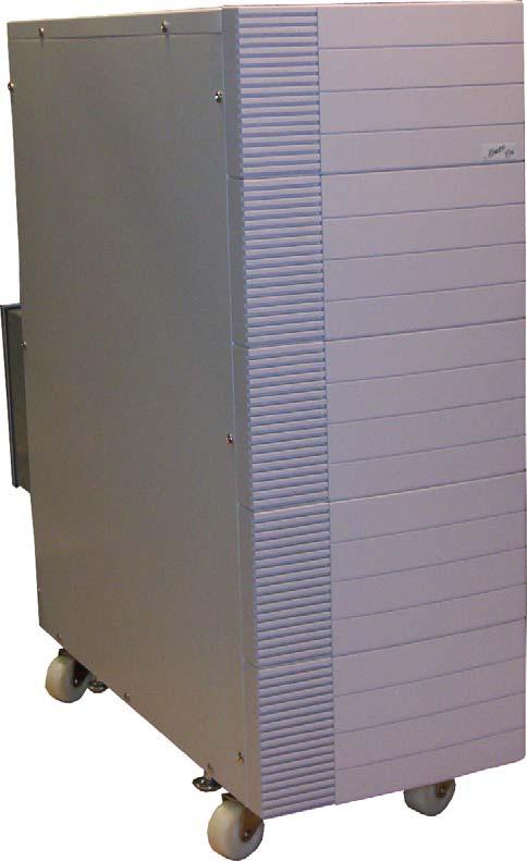
17 4.4. Location The Bypass System is intended for installation in a temperature-controlled indoor area, free of conductive contaminants. Qualified individuals should conduct installation. Below is an example of one installation. BATTERY PACK Always "On" Figure 4.1 Typical System Layout - Front View Figure 4.2 Typical System Layout - Rear View M43_T_Series_Ext_Bypass_Manual V
18 5. Installation WARIG! The Bypass system should be installed by a qualified technician or personnel and wired in accordance with local and national electrical codes. Be sure the polarities and voltage match the rating of the unit. Check that the loads being protected are within the capacity of the system. Ensure no power has been applied to the systems and nothing has been turned on before proceeding Bypass Unit ote: All connections are available at the rear of the Bypass unit, See Figure 3.2 For a detailed wiring diagram, See Figure Connect the critical loads to AC Output located on the Input/Output terminal block of the Bypass Unit. 2. Connect input cabling from the utility source to AC Input located on the Input/Output terminal block of the Bypass Unit. WARIG! Do OT apply utility at this time. WARIG! Do OT turn O the at this time T Series 1. If an optional Battery Bank has been purchased, connect the Battery Bank to the. Refer to the Battery Bank Operators Manual for instructions. 2. Connect input cabling from To AC Input located on the Input/Output terminal block of the Bypass Unit to the input terminal block. 3. Connect the output of the T Series to From AC Output located on the Input/Output terminal block of the Bypass Unit. WARIG! Do OT apply utility at this time. WARIG! Do OT turn the on at this time. M43_T_Series_Ext_Bypass_Manual V
19 EXT BATT T SERIES AC TO AC BYPASS UIT FROM AC AC B+ B- GD O/P O/P O/P GD O/P O/P O/P O/P O/P GD B+ B- TO OPTIOAL BATTERY CABIET(S) GD UTILITY GD TO LOAD Figure 5.1 External Wiring Diagram for the 28VAC and 24VAC system EXT BATT T SERIES 24 VAC 12 VAC AC 24 VAC TO AC BYPASS UIT 12 VAC FROM AC AC B+ B- GD O/P O/P L GD L O/P O/P L O/P O/P GD B+ B- GD L GD TO OPTIOAL 12 Vac BATTERY CABIET(S) TO LOAD UTILITY 12 VAC Figure 5.2 External Wiring Diagram for the 12VAC systems M43_T_Series_Ext_Bypass_Manual V
20 Figure 5.3 External Wiring Diagram for the 28//12VAC systems M43_T_Series_Ext_Bypass_Manual V
21 6. Operation 6.1. System Start Up 1. Ensure that all connections are secure and correct as per Installation Instructions. 2. Confirm that the Bypass Switch on the is in the IV position. 3. Confirm that the Bypass Switch on the Bypass Unit is in the IV position. 4. Confirm that the Battery Breaker on the is in the OFF position. 5. Confirm that the Input Breaker on the is in the OFF position. 6. Confirm that the Input Breaker on the Bypass Unit is in the OFF position. 7. Remove the cover plate on any Battery Cabinets (if applicable). 8. Switch all Battery Breakers on the Battery Cabinets to the O position (if applicable). 9. Switch the Battery Breaker on the to the O position. 1. Apply utility power to the system. 11. Switch the Input Breaker on the Bypass Unit to the O position. 12. Switch the Input Breaker on the to the O position. The will enter Stand-By Mode. The LCD will become illuminated, and fans will start. 13. Press the O/OFF Button on the front panel of the to turn it O (hold the O/OFF Button for 3 seconds or until the beeps and displays Ready On ). The will automatically perform a self-test and then go to line mode. 14. Turn on loads sequentially as required. M43_T_Series_Ext_Bypass_Manual V
22 6.2. System Shutdown Load will lose power 1. Turn off loads sequentially as required. 2. Press the O/OFF Button on the front panel of the to turn it OFF (hold the O/OFF Button for 5 seconds or until the beep stops and the LCD displays Shutdown ). The will shutdown. The LCD will display Off for a few seconds and then switch to Stand-By Mode. 3. Switch the Input Breaker on the to the OFF position, and wait 1 seconds before proceeding. The will fully shutdown. The fans will stop, and the LCD will extinguish. 4. Switch the Battery Breaker on the to the OFF position. 5. Switch the Battery Breakers on any attached Battery Cabinets to the OFF position (if applicable). 6. Switch the Input Breaker on the Bypass Unit to the OFF position. 7. Remove utility power from the system. The System is now completely shutdown Bypass Procedures This Bypass System provides the user with the ability to isolate the from the utility power without disrupting power to the load. The can be completely shutdown and even removed so that maintenance can be performed safely, without the load experiencing any downtime. Caution: Only operate the Bypass switch on the Bypass Unit when the is in MAITEACE BYPASS mode. Entering Bypass Mode 1. Put the into Maintenance Bypass Mode by following the instructions found in the Operators Manual. 2. Turn the Bypass Switch on the Bypass Unit to the BYPASS position. 3. Switch the Input Breaker on the Bypass Unit to the OFF position. The is now isolated from utility. Restoring ormal Operation 1. Ensure the is in MAITEACE BYPASS mode. 2. Switch the Input Breaker on the Bypass Unit to the O position. 3. Turn the Bypass Switch on the Bypass Unit to the ORMAL position. 4. Put the into ormal Operation by following the instructions found in the Operators Manual. The system is now operating in ormal Mode. M43_T_Series_Ext_Bypass_Manual V
23 7. Troubleshooting Problem Possible Cause Action to Take Cannot be switched to Utility not available at Confirm Utility supply and Bypass Mode input of bypass system connection. Cannot be switched to Mode power not available Confirm supply and connection Caution: Only operate the Bypass switch when the is in MAITEACE BYPASS mode. M43_T_Series_Ext_Bypass_Manual V
24 8. COTACT IFORMATIO 8.1. Additional Purchases or Upgrades Always On Systems Inc. Bldg 1 15 Campion Road, Kelowna, BC, Canada, V1X 7S8 Phone: (25) Ext 451 Fax: (25) sales@alwayson.com Website: QA / Warranty Questions Always On Systems Inc. Bldg 1 15 Campion Road, Kelowna, BC, Canada, V1X 7S8 Phone: (25) Ext 29 Fax: (25) qa@alwayson.com Website: Software Questions Always On Systems Inc. Bldg 1 15 Campion Road, Kelowna, BC, Canada, V1X 7S8 Phone: (25) Ext 24 Fax: (25) webmaster@alwayson.com Website: M43_T_Series_Ext_Bypass_Manual V
Genie Smart Cabinet - UPS Powered Distribution Unit User Manual
 Genie Smart Cabinet - UPS Powered Distribution Unit User Manual M2102_Genie_Breaker_Cabinet_Manual V1.0 2012-06-12 M2102_Genie_Breaker_Cabinet_Manual V1.0 2012-06-12 Table of Contents 1. CAUTION 1 2. IMPORTANT
GES-202TLP Traffic Light System Installation Manual
 GES-202TLP Traffic Light System Installation Manual M1603_TLP_Installation_Manual V1.0 2012-06-12 IMPORTANT EMERGENCY SHUTDOWN PROCEDURE ON THE INSIDE OF REAR COVER NOTE: The instructions contained in
ALW Battery & Battery Bank Specifications
 ALW Battery & Battery Bank Specifications UL Listed: MH43 Version. June, 8 ALW36-UPS 4 UL Listed: MH43 our rate (.6A) 36A our rate (3.33A) 33.3A our rate (.76A) 8.8A 77 ( C) our rate (.6A).6A ute rate
Aurora Single Phase Emergency Lighting Inverters
 Aurora Single Phase Emergency Lighting Inverters True Sine Wave On-Line Single Phase Emergency Lighting Inverters AURORA Series Emergency Lighting AC Inverters are among the most reliable systems available
Uninterruptible Power Supply
 AC/DC Din Rail UPS System Single Phase Input, Single Phase Output Uninterruptible Power Supply 600VA UPS System AC/DC Din Rail Mount Line Interactive (PWM): 600VA User Manual M1201_Din_Rail_AC-DC_600VA_Manual
Uninterruptible Power Supply USER MANUAL Version 1.4. Always On UPS Systems Inc. GES-801L, GES-102L, GES-152L, GES-202L, GES-302L
 GES L-Series Single Phase Input, Single Phase Output Uninterruptible Power Supply USER MANUAL Version 1.4 GES-801L, GES-102L, GES-152L, GES-202L, GES-302L Line Interactive (True Sine Wave): 800VA, 1000VA,
Nova UAC (NV-UAC-M) Modified Sine Wave 650W 800W 1000W
 Modified Sine Wave 650W 800W 1000W") ova UAC (V-UAC-M) Modified Sine Wave 650W 800W 1000W ISTRUCTIOS IMPORTAT SAFEGUARDS When using electrical equipment, basic safety precautions should always be followed including the following: 1. READ
ova UAC (V-UAC-M) Modified Sine Wave 650W 800W 1000W ISTRUCTIOS IMPORTAT SAFEGUARDS When using electrical equipment, basic safety precautions should always be followed including the following: 1. READ
Installation and Operation Back-UPS BX550CI-CN
 Installation and Operation Back-UPS BX550CI-CN Safety and General Information This unit is intended for indoor use only. Do not operate this unit in direct sunlight, in contact with fluids, or where there
Users Manual. Defender 1 8.0KW to 14.0KW Online Emergency Lighting Inverter. Technical Manual # Revision B
 Users Manual Defender 1 8.0KW to 14.0KW Online Lighting Inverter Technical Manual #018-0102-01 Revision B Phone: 1.877.DSPM.POWER 1.877.377.6769 Fax: 909.930.3335 Website: www.dspmanufacturing.com E-Mail:
Users Manual. Cobra Plus Stand-By Emergency Lighting Inverter. Technical Manual # Revision B
 Users Manual Cobra Plus Stand-By Lighting Inverter Technical Manual #018-0110-01 Revision B Phone: 1.877.DSPM.POWER 1.877.377.6769 Fax: 909.930.3335 Website: www.dspmanufacturing.com E-Mail: techsupport@dspmanufacturing.com
Installation and Operation Manual Back-UPS BR800/1100CI-IN
 Installation and Operation Manual Back-UPS BR800/1100CI-IN Safety and General Information There are no serviceable parts in the Back-UPS. Do not attempt to open or repair the Back-UPS as this will void
Limousin II User Manual
 Limousin II User Manual 600VA Uninterruptible Power Supply Single Phase Input, Single Phase Output M0601_Limo_II_Series_Manual V1.6 2012-06-12.doc SAVE THESE SAFETY INSTRUCTIONS 1. This manual contains
Galaxy Receiving and Unpacking 09/
 Galaxy 5500 20 120 kva 400 V Receiving and Unpacking 09/2015 www.schneider-electric.com Legal Information The Schneider Electric brand and any registered trademarks of Schneider Electric Industries SAS
Informer Compact Series
 IMPORTANT SAFETY INSTRUCTIONS Informer Compact Series LINE-INTERACTIVE SINEWAVE UPS Uninterruptible Power System WARNING : (SAVE THESE INSTRUCTIONS) This manual contains important safety instructions.
RT Series Step Down Transformer for RT Series UPS 6-10kVA UL Input Vac Output Vac User Guide
 RT Series Step Down Transformer for RT Series UPS 6-10kVA UL Input 208-240 Vac Output 208-120 Vac User Guide UNLESS SPECIFICALLY AGREED TO IN WRITING, SELLER (A) MAKES NO WARRANTY AS TO THE ACCURACY, SUFFICIENCY
User Manual Back-UPS BX650CI-MS 230 Vac with AVR
 User Manual Back-UPS BX650CI-MS 230 Vac with AVR Overview Safety and General Information Inspect the package contents upon receipt. Notify the carrier and dealer if there is any damage. Read the Safety
Delta UPS - Ultron Family. HPH Integrated Battery Series, Three Phase 20/30/40 kva. User Manual.
 ORMAL BATTERY BYPASS FAULT ESC O OFF The power behind competitiveness Delta UPS - Ultron Family HPH Integrated Battery Series, Three Phase 20/30/40 kva User Manual www.deltapowersolutions.com Save This
Installation and Operation Manual Back-UPS BR1000-CH
 Installation and Operation Manual Back-UPS BR1000-CH Complete, sign and return the Quality Assurance card or register the product online at www.apc.com. Safety This unit is intended for indoor use only.
BULL POWER Line Conditioner Regulating Power Bar
 BULL POWER Line Conditioner Regulating Power Bar Auto Voltage Regulation User s Manual TABLE OF CONTENTS INTRODUCTION 1 1. IMPORTANT SAFETY INSTRUCTIONS 2 2. PRESENTATION 2 3. INSTALLATION 3 4. OPERATION
The power behind competitiveness. Delta UPS - Ultron Family. DPS Series, Three Phase 300/ 400/ 500 kva. User Manual.
 The power behind competitiveness Delta UPS - Ultron Family DPS Series, Three Phase 300/ 400/ 500 kva User Manual www.deltapowersolutions.com Save This Manual This manual contains important instructions
User Manual Back-UPS BC500-RS, BC650-RS 650 VA 230 V
 User Manual Back-UPS BC500-RS, BC650-RS 650 VA 230 V Important Safety Information Read the instructions carefully to become familiar with the equipment before trying to install, oate, service or maintain
Alphapower. Maintenance Bypass Switch. Some key features include:
 Maintenance Bypass Switch Alphapower The MBSW is a manual maintenance bypass switch designed to isolate AC input and output to allow for routine UPS maintenance without load interruption. The purpose of
Installation and Operation Manual Back-UPS BX1100CI-CN
 Installation and Operation Manual Back-UPS BX1100CI-CN Safety and General Information This unit is intended for indoor use only. Do not operate this unit in direct sunlight, in contact with fluids, or
User Manual. NetGuard IMPORTANT. PSD 650/1200/1600 Line Interactive UPS Uninterruptible Power Supply System. UPS Monitoring Software
 User Manual Thank you for purchasing the Defender 650/1200/1600. It is designed to provide safe and reliable power protection to your precious electronics equipment. Before you start using the product,
User Manual Easy UPS BV Series 500VA, 650VA, 800VA, 1000VA Safety and General Information
 User Manual Easy UPS BV Series 500VA, 650VA, 800VA, 1000VA Safety and General Information SAVE THESE INSTRUCTIONS This manual contains important instructions that should be followed during installation
IMPORTANT SAFEGUARDS
 INSTRUCTION MANUAL NON-INTERRUPTIBLE AC INVERTER SYSTEM MODEL EAC FTM 350 FOR EMERGENCY LIGHTING POWER IMPORTANT SAFEGUARDS When using electrical equipment, basic safety precautions should always be followed,
USER MANUAL. Blazer Vista 1000/1400/2000. Uninterruptible Power System
 USER MANUAL Blazer Vista 1000/1400/2000 Uninterruptible Power System IMPORTANT SAFETY INSTRUCTIONS SAVE THESE INSTRUCTIONS This manual contains important instructions for model Blazer Vista 1000/1400/2000
XPC-EBP64 External Battery Pack User & Installation Manual Xtreme Power Conversion Corporation. All rights reserved.
 XPC-EBP64 User & Installation Manual www.xpcc.com 2015. All rights reserved. (Rev 9/28/15) Table of Contents Introduction...5 Product Description...5 Extended Battery Pack Configurations...6 Safety Information...7
Installation and Operation Manual Back-UPS BX800CI-ZA/BX1100CI-ZA
 Installation and Operation Manual Back-UPS BX800CI-ZA/BX1100CI-ZA Inventory Safety and General Information bu001c This unit is intended for indoor use only. Do not operate this unit in direct sunlight,
On Line UPS. LUC 1000E / LUC 2000E / LUC 3000E User Manual
 On Line UPS LUC 1000E / LUC 2000E / LUC 3000E User Manual Save This Manual Please read this manual carefully prior to storage, installation, wiring, operation and maintenance of the UPS. This manual contains
Power Inverter. User s Manual. Diamond Series CPD1200EILCD
 Power Inverter Diamond Series CPD1200EILCD User s Manual 2 TABLE OF CONTENTS 1 IMPORTANT SAFETY INSTRUCTIONS..4 2 INSTALLATION....5 2-1 Unpacking...5 2-2 Product Overview & Outlook..5 2-3 Power Requirements
SIEMENS. XJ-L Busway Systems. Storage, Installation and Maintenance Instructions for... Piece No. 32-J Rev 3
 SIEMENS XJ-L Busway Systems Storage, Installation and Maintenance Instructions for... Piece No. 32-J-1010-01 Rev 3 ~DANGER Hazardous voltages and exposed electrical conductors will cause death, serious
U n i n t e r r u p t i b l e P o w e r S y s t e m
 SMART ON-LINE UPS User s Manual U n i n t e r r u p t i b l e P o w e r S y s t e m Smart On-Line UPS 2KVA ~ 20KVA 20KVA Exhaust hole (16)Main breaker (12)Heat exhaust hole (15)Telephone (Rj11) or network
GWI Rev. 1 October 2007 Supersedes Rev. 0 Dated February 2004
 Installation Instructions Series I Encapsulated Current Limiting Fuse GWI 701-4 Rev. 1 October 2007 Supersedes Rev. 0 Dated February 2004 TABLE OF CONTENTS Section Page 1. Introduction 2 2. Safety Information
Back-UPS 650 VA 230 V with AVR (BX650CI-ZA)
") Back-UPS 650 VA 230 V with AVR (BX650CI-ZA) Overview Do not install the unit in direct sunlight, in areas of excessive heat or humidity, or in contact with fluids ON/OFF button Battery connector Circuit
Back-UPS 650 VA 230 V with AVR (BX650CI-ZA) Overview Do not install the unit in direct sunlight, in areas of excessive heat or humidity, or in contact with fluids ON/OFF button Battery connector Circuit
Illuminator Series CR NEMA 3R
 Illuminator Series CR NEMA 3R GUIDE SPECIFICATIONS And TECHNICAL DESCRIPTION For 3.0, 4.0, 5.0, 6.5, 8.0kVA / kw Series CR - Single Phase Uninterruptible Power System This description contains all the
Noran Tel. a subsidiary of Westell Inc. Fuse Panel Technical Practice NPGMT /10 GMT NEBS Level 3 Verified
 1107-03B Aug 16, 2011 a subsidiary of Westell Inc Fuse Panel Technical Practice NPGMT1107 10/10 GMT NEBS Level 3 Verified FEATURES 2 isolated groups (busses) of 10 GMT style fuses in each (20Amps/GMT position
User Manual 3KVA/5KVA INVERTER / CHARGER. Version: 1.1
 User Manual 3KVA/5KVA IVERTER / CHARGER Version: 1.1 Table Of Contents ABOUT THIS MAUAL... 1 Purpose... 1 Scope... 1 SAFETY ISTRUCTIOS... 1 ITRODUCTIO... 2 Features... 2 Basic System Architecture... 2
OutdoorXUPS-600AHV-8364
 OutdoorXUPS-600AHV-8364 TSi Power s OutdoorXUPS-600AHV-8364 provides secure and uninterrupted 230 vac power to critical loads. 1) Weather-tight metal cabinet (IP44 or NEMA 3R rated) 2) 2A and 2B are wide
Matrix AP 400V 690V INSTALLATION GUIDE. Quick Reference. ❶ How to Install Pages 6 20 ❷ Startup/Troubleshooting Pages WARNING
 Matrix AP 400V 690V INSTALLATION GUIDE FORM: MAP-IG-E REL. May 2017 REV. 002 2017 MTE Corporation WARNING High Voltage! Only a qualified electrician can carry out the electrical installation of this filter.
Matrix APAX. 380V-415V 50Hz TECHNICAL REFERENCE MANUAL
 Matrix APAX 380V-415V 50Hz TECHNICAL REFERENCE MANUAL WARNING High Voltage! Only a qualified electrician can carry out the electrical installation of this filter. Quick Reference ❶ Performance Data Pages
Onfiniti. 1 Phase UPS
 Onfiniti 1 Phase UPS Today's business continuity demands a cost-effective power protection solution, for ensuring Power Continuity and Power Quality with optimal Total Cost of Ownership (TCO). The UPS
3. MAJOR SYSTEM COMPONENTS Emergency Lighting Power System shall consist of the following major subsystems:
 TECHNICAL GUIDE SPECIFICATIONS Power-Lite Single Phase, (200 to 490 Watts) UL924 Central Lighting Inverter 1. SCOPE The Emergency Lighting Power System shall be a solid-state single phase unit designed
USER'S GUIDE. WiseHP11 SINGLE PHASE HIGH PRECISION AVR SERVO-MOTOR AUTOMATIC VOLTAGE STABILIZER
 USER'S GUIDE WiseHP11 SINGLE PHASE HIGH PRECISION AVR SERVO-MOTOR AUTOMATIC VOLTAGE STABILIZER LEN.MAN.STA.145 Rev.5.00/2010 CONTENTS 1. SAFETY INSTRUCTIONS 1 2. INTRODUCTION 2 3. FRONT PANEL AND INSIDE
Uninterruptible Power System
 USER'S MANUAL Emergency Backup Power Supply For Use With Computer Loads Only Power Surge/Noise Protection Intelligent Auto-Shutdown Software Internet Line Protection Cost Efficiency UPS AVR Protection
Vission 20/20 Retrofit Instructions
 Vission 20/20 Retrofit Instructions Table of Contents Sections Page.0 General Information... 3 2.0 Vission 20/20 Retrofit Instructions... 4 2. Removal... 4 2.2 Installation... 5 3.0 Field Wiring Instructions...
M Series External Battery Frame. User Guide
 M Series External Battery Frame User Guide M 24-065-144 BF-NB M 24-100-144 BF-NB M 24-120-144 BF-NB UNLESS SPECIFICALLY AGREED TO IN WRITING, SELLER (A) MAKES NO WARRANTY AS TO THE ACCURACY, SUFFICIENCY
Operating Instructions for PAC800 Battery Charger
 Operating Instructions for PAC800 Battery Charger General Safety The charger may only be used for the specified battery types. This battery charger is supplied with pre-set charging curves that are adapted
Foreword
 Foreword Content 1. Summary 2. Safety instruction Safety Symbol Indication Attention Static discharge sensitive Electric shock Dangerous Indicate risk of serious injury or death or seriously damage the
AIS and 40 kva 400 V. Site Preparation and Installation Manual
 AIS 3100 20 and 40 kva 400 V Site Preparation and Installation Manual www.apc.com AIS 3100 20 and 40 kva 400 V Site Preparation and Installation Manual www.apc.com IMPORTANT SAFETY INSTRUCTIONS SAVE THESE
Megohmmeter Test Probe
 Megohmmeter Test Probe User Manual ENGLISH www.aemc.com CHAUVIN ARNOUX GROUP Copyright Chauvin Arnoux, Inc. d.b.a. AEMC Instruments. All rights reserved. No part of this documentation may be reproduced
dv Sentry TM 208V 600V INSTALLATION GUIDE Quick Reference ❶ How to Install Pages 6 14 ❷ Startup/Troubleshooting Pages WARNING
 dv Sentry TM 208V 600V INSTALLATION GUIDE FORM: DVS-IG-E REL. January 2018 REV. 003 2018 MTE Corporation High Voltage! Only a qualified electrician can carry out the electrical installation of this filter.
REFERENCE MANUAL FORM: MX-TRM-E REL REV MTE
 Matrix APAX 380V-415V 50Hz TECHNICAL REFERENCE MANUAL FORM: MX-TRM-E REL. September 2014 REV. 002 2014 MTE Corporation WARNING High Voltage! Only a qualified electrician can carry out the electrical installation
User Manual 3KVA/5KVA 24V INVERTER / CHARGER. Version: 1.1
 User Manual 3KVA/5KVA 24V IVERTER / CHARGER Version: 1.1 Table Of Contents ABOUT THIS MAUAL... 1 Purpose... 1 Scope... 1 SAFETY ISTRUCTIOS... 1 ITRODUCTIO... 2 Features... 2 Basic System Architecture...
4 amp (100VA). - 4 amp (100VA). - Four (4) Fuse Protected - Four (4) PTC Protected
. - 4 amp (100VA). - Four (4) Fuse Protected - Four (4) PTC Protected") ALTV244 Series CCTV Power Supplies Installation Guide Models Include: ALTV244 ALTV244CB -24VAC @ 4 amp (100VA). - 24VAC @ 4 amp (100VA). - Four (4) Fuse Protected - Four (4) PTC Protected ALTV244175 ALTV244175CB
ALTV244 Series CCTV Power Supplies Installation Guide Models Include: ALTV244 ALTV244CB -24VAC @ 4 amp (100VA). - 24VAC @ 4 amp (100VA). - Four (4) Fuse Protected - Four (4) PTC Protected ALTV244175 ALTV244175CB
PEC 827E. 120 VAC AC Distribution Shelf. Critical Power Product Manual
 Critical Power Product Manual PEC 827E 120 VAC AC Distribution Shelf 6180498P (23 For Conduit), 6180529P (23 W/Outlets) 6180542P (19 For Conduit), 6180533P (19 W/Outlets) This document issue 4ge is updated
Power InverterTM Watt. Continuous. User's Manual. WAGAN Corp. Limited Warranty Registration Form. Item no
 WAGAN Corp. Limited Warranty Registration Form All WAGAN Corporation products are warranted to the original purchaser of this product. Warranty Duration: This product is warranted to the original purchaser
Noran Tel. FUSE PANEL Technical Practice N21C110-NCY 5/5 GMT (20Amp GMT) NEBS Level 3 Certified
 NEBS Level 3 Certified") 0322-03D Sept 02, 2010 Noran Tel FUSE PANEL Technical Practice N21C110-NCY 5/5 GMT (20Amp GMT) NEBS Level 3 Certified FEATURES 2 isolated groups (busses) of 5 GMT fuses each (20Amps/GMT position). Polarity
0322-03D Sept 02, 2010 Noran Tel FUSE PANEL Technical Practice N21C110-NCY 5/5 GMT (20Amp GMT) NEBS Level 3 Certified FEATURES 2 isolated groups (busses) of 5 GMT fuses each (20Amps/GMT position). Polarity
USER S MANUAL CONTENTS. Uninterruptible Power Supply 1. INTRODUCTION SAFTY INSTRUCTION SYSTEM DESCRIPTION... 4
 USER S MANUAL PowerWalker VFI 1000 / 3000VA CONTENTS 1. INTRODUCTION...... 1 2. SAFTY INSTRUCTION......... 2 3. SYSTEM DESCRIPTION......... 4 4. CABLE CONNECTION......... 7 5. OPERATION...... 8 6. TROUBLE
Uninterruptible Power System
 USER'S MANUAL Emergency Backup Power Supply For Use With Computer Loads Only Power Surge/Noise Protection Intelligent Auto-Shutdown Software Internet Line Protection Cost Efficiency UPS 1 st Edition Uninterruptible
Fortress 1 Outdoor Emergency Central Lighting Inverter (CLI) Technical Specifications
 Technical Specifications") Fortress 1 Outdoor Emergency Central Lighting Inverter (CLI) Technical Specifications PART 1 GENERAL 1.1 SUMMARY A. This specification describes a single phase, on-line, double conversion, solid state
Fortress 1 Outdoor Emergency Central Lighting Inverter (CLI) Technical Specifications PART 1 GENERAL 1.1 SUMMARY A. This specification describes a single phase, on-line, double conversion, solid state
LED Canister Light System
 LED 1200 - Canister Light System LED1200 Canister Light System Document Control #HO.11.01.001 Hollis 1540 North 2200 West Salt Lake City, UT 84116 USA Toll-Free: 1-888-270-8595 www.hollis.com 1 TABLE OF
Cobra 3 Stand-By Emergency Central Lighting Inverter (CLI) Technical Specifications
 Technical Specifications") Cobra 3 Stand-By Emergency Central Lighting Inverter (CLI) Technical Specifications PART 1 GENERAL 1.1 SUMMARY A. This specification describes a stand-by, three-phase, solid state Lighting Inverter System
Cobra 3 Stand-By Emergency Central Lighting Inverter (CLI) Technical Specifications PART 1 GENERAL 1.1 SUMMARY A. This specification describes a stand-by, three-phase, solid state Lighting Inverter System
USER MANUAL. PowerMust 1400/2000 LCD. Uninterruptible Power System
 USER MANUAL PowerMust 1400/2000 LCD Uninterruptible Power System IMPORTANT SAFETY INSTRUCTIONS SAVE THESE INSTRUCTIONS This manual contains important instructions for model Power Must 1400/2000 LCD that
CONTENTS 1. INTRODUCTION SAFTY INSTRUCTION CABLE CONNECTION SYSTEM DESCRIPTION INVERTER OPERATION...
 CONTENTS 1. INTRODUCTION...... 1 2. SAFTY INSTRUCTION.......... 2 3. CABLE CONNECTION.......... 4 4. SYSTEM DESCRIPTION............ 5 5. INVERTER OPERATION... 11 6. TROUBLE SHOOTING GUIDE....... 16 7.
Product Installation Document
 Honeywell 12 Clintonville Road Northford, CT 064721610 http://www.honeywellpower.com HP1205UL4, HP1205UL8, HP12010UL8, HP1210UL16 Power Supplies/Distribution Units PN 0618131: A 07/18/13 Product Installation
Linear Actuator Swing Gate Operator Installation Manual Model # LA405-24
 Linear Actuator Swing Gate Operator Installation Manual Model # LA405-24 2 Contents Contents Product Information and Specs. 3 Mechanical 3 Electrical, Line Connections 3 Electrical, Control Connections
1. Contents 1. CONTENTS INTRODUCTION SAFETY WARNINGS POWER TILT STANDARD OPERATING INSTRUCTIONS... 5.
 1. Contents 1. CONTENTS..... 2. INTRODUCTION..... 3. SAFETY WARNINGS..... 4. POWER TILT STANDARD OPERATING INSTRUCTIONS....... 5. POWER SEAT LIFT STANDARD OPERATING INSTRUCTIONS...... 6. POWER TILT / SEAT
U00X ULTRASONIC LEVEL SWITCH. Ultrasonic Liquid Level Switches INSTALLATION AND OPERATIONS MANUAL. For Models: U002, U003 & U004
 U00X ULTRASONIC LEVEL SWITCH INSTALLATION AND OPERATIONS MANUAL Ultrasonic Liquid Level Switches For Non-Hazardous Locations For Models: U002, U003 & U004 READ THIS MANUAL PRIOR TO INSTALLATION This manual
DUAL/TRIPLE MPPT INVERTER / CHARGER. User Manual
 DUAL/TRIPLE MPPT IVERTER / CHARGER User Manual Table Of Contents ABOUT THIS MAUAL... 1 Purpose... 1 Scope... 1 SAFETY ISTRUCTIOS... 1 ITRODUCTIO... 2 Features... 2 Basic System Architecture... 2 Product
WF-5100 Series True Sine Wave Inverters
 Operator s Manual WF-5100 Series True Sine Wave Inverters WF-9900 Series WF-5118 WF-5120 ( The Inverter model number is located on the label on top of the enclosure) Distributed in the U.S.A. and Canada
DANGER. See Wiring Diagrams on page 7 for illustrations of both internal and connection wiring diagrams. WARNING
 January 009 I4-403C A1800 APHA Meter Installation Instructions General This leaflet contains general installation instructions for 4-wire and 3-wire applications of the A1800 APHA meters. All meters are
www. ElectricalPartManuals. com TOSHIBA 1600EP SERIES MANUFACTURED IN THE U.S.A. OPERATION MANUAL BATTERY CABINET SYSTEM SINGLE PHASE- 8/10/14/18 kva
 August 2003 Part# 55416-000 TOSHIBA BATTERY CABINET SYSTEM SINGLE PHASE- 8/10/14/18 kva 1600EP SERIES MANUFACTURED IN THE U.S.A. OPERATION MANUAL 1600EP SERIES SINGLE PHASE- 8/10/14/18 kva BATTERY CABINET
Powerware Vdc Extended Battery Cabinet User s Guide.
 Powerware 9125 48 Vdc Extended Battery Cabinet User s Guide www.powerware.com FCC Part 15 Class A EMC Statements NOTE This equipment has been tested and found to comply with the limits for a Class A digital
Westell FUSE PANEL. Technical Practice N Position Type VDC Floating
 530-101760 REV C 0808-03C December 7, 2012 Westell FUSE PANEL Technical Practice 180108-N-0808 8 Position Type 70 130 VDC Floating FEATURES Single floating input distributing power via Type-70 fuses each
LINE INTERACTIVE LONG BACKUP TIME UPS EN-1000 / EN-2000 USER S MANUAL
 LINE INTERACTIVE LONG BACKUP TIME UPS EN-1000 / EN-2000 USER S MANUAL Important Safety Information Before installing UPS EN-1000/ EN-2000, please read the operating instructions carefully. Special attention
WF-5110R True Sine Wave Inverter
 Operator s Manual WF-5110R True Sine Wave Inverter WF-9900 Series WF-5110R ( The Inverter model number is located on the label on top of the enclosure) Distributed in the U.S.A. and Canada by ARTERRA DISTRIBUTION
USER MANUAL. Power GUARD UPS. Uninterruptible Power System
 USER MANUAL Power GUARD UPS Uninterruptible Power System IMPORTANT SAFETY INSTRUCTIONS SAVE THESE INSTRUCTIONS This manual contains important instructions for Power GUARD that should be followed during
ACC Series Power Conditioner OPERATION & INSTALLATION MANUAL
 ACC Series Power Conditioner OPERATION & INSTALLATION MANUAL PHASETEC digital power conditioners are designed to safely operate electrical equipment in the harshest power quality environments. With a wide
Symmetra PX. 48 kw 400 V, 96 kw 400 V, 100 kw 208 V, 160 kw 400 V. Receiving and Unpacking 01/2016.
 Symmetra PX 48 kw 400 V, 96 kw 400 V, 100 kw 208 V, 160 kw 400 V Receiving and Unpacking 01/2016 www.schneider-electric.com Legal Information The Schneider Electric brand and any registered trademarks
Test Cabinet (Inspection Box) Instructions. for Testing Accessories on Manually and Electrically Operated EntelliGuard G Low Voltage Circuit Breakers
 Instructions. for Testing Accessories on Manually and Electrically Operated EntelliGuard G Low Voltage Circuit Breakers") DEH41480 Test Cabinet (Inspection Box) for Testing Accessories on Manually and Electrically Operated EntelliGuard G Low Voltage Circuit Breakers Instructions 1 Table of Contents Section 1. Introduction
DEH41480 Test Cabinet (Inspection Box) for Testing Accessories on Manually and Electrically Operated EntelliGuard G Low Voltage Circuit Breakers Instructions 1 Table of Contents Section 1. Introduction
Uninterruptible Power System
 USER'S MANUAL Emergency Backup Power Supply For Use With Computer Loads Only Power Surge/Noise Protection Intelligent Auto-Shutdown Software Internet Line Protection Cost Efficiency AVR Protection Compact
FUSE PANEL. Technical Practice N N-L33 10/10 GMT Front Access NEBS Level 3 Certified
 530-063 Rev K 0220-03K November 3, 202 Westell FUSE PANEL Technical Practice N25020-N-L33 0/0 GMT Front Access NEBS Level 3 Certified FEATURES 2 isolated groups (busses) of 0 GMT fuses in each (5Amps/GMT
FUSE PANEL Technical Practice FDP /10 GMT NEBS Level 3 Certified
 0521-03A May 2006 FUSE PANEL Technical Practice FDP 1010 10/10 GMT NEBS Level 3 Certified FEATURES 2 isolated groups (busses) of 10 GMT fuses in each (15Amps/GMT position) Polarity insensitive (+/-24 or
FUSE PANEL Technical Practice N N-L34 20/20 GMT (23 panel) NEBS Level 3 Certified
 NEBS Level 3 Certified") 530-101732 Rev L 0223-03K September 30, 2010 Westell FUSE PANEL Technical Practice N250140-N-L34 20/20 GMT (23 panel) NEBS Level 3 Certified FEATURES 2 isolated groups (busses) of 20 GMT fuses each (15Amps/GMT
530-101732 Rev L 0223-03K September 30, 2010 Westell FUSE PANEL Technical Practice N250140-N-L34 20/20 GMT (23 panel) NEBS Level 3 Certified FEATURES 2 isolated groups (busses) of 20 GMT fuses each (15Amps/GMT
MTE SERIES RLW. World REACTORS USER MANUAL PART NO. INSTR 030 REL MTE Corporation
 MTE SERIES RLW World REACTORS USER MANUAL PART NO. INSTR 030 REL. 090529 2009 MTE Corporation IMPORTANT USER INFORMATION NOTICE MTE Series RLW Line/Load Reactors are components designed to improve the
WF-5110R True Sine Wave Inverter
 Operator s Manual WF-5110R True Sine Wave Inverter WF-9900 Series WF-5110R ( The Inverter model number is located on the label on top of the enclosure) Distributed in the U.S.A. and Canada by ARTERRA DISTRIBUTION
XS400 Load Bank. Read all instructions before using the load bank. Contents
 Read all instructions before using the load bank Contents 1) Components... 3 Total Assembly... 3 2) Specifications... 4 3) Receiving... 4 4) Safety... 5 a) Grounding cam... 6 b) Power connections... 6
CTFRP Series Power Supplies
 CTFRP Series Power Supplies Ferroresonant Non-Standby Power Supplies User Manual Myers Power Products 6/2013 CTFRP Series Manual Chapter 1 General Information The Myers CTFRP Series Power Supply provides
Galaxy kva 3:3 and 3:1. Receiving and Unpacking. 380/400/415 and 208/220 V 04/2016.
 Galaxy 3500 10-40 kva 3:3 and 3:1 Receiving and Unpacking 380/400/415 and 208/220 V 04/2016 www.schneider-electric.com Legal Information The Schneider Electric brand and any registered trademarks of Schneider
Power Lynx 3 Uninterruptible Power System (UPS) Technical Specifications
 Technical Specifications") Power Lynx 3 Uninterruptible Power System (UPS) Technical Specifications PART 1 GENERAL 1.1 SUMMARY A. This specification describes a three phase, on-line, double conversion, solid state Uninterruptible
Power Lynx 3 Uninterruptible Power System (UPS) Technical Specifications PART 1 GENERAL 1.1 SUMMARY A. This specification describes a three phase, on-line, double conversion, solid state Uninterruptible
CONTENTS 1. INTRODUCTION SAFTY INSTRUCTION CABLE CONNECTION SYSTEM DESCRIPTION OPERATION... 9
 USER MANUAL 1 CONTENTS 1. INTRODUCTION... 1 2. SAFTY INSTRUCTION... 3 3. CABLE CONNECTION... 4 4. SYSTEM DESCRIPTION... 5 5. OPERATION... 9 6. TROUBLE SHOOTING GUIDE... 25 7. OPERATION MODES..... 27 8.
Installation and Operation Smart-UPS SUA500PDR
 Installation and Operation Smart-UPS SUA500PDR Mount the UPS on DIN Rail This unit is designed to mount on a heavy duty DIN rail or on the back panel of an enclosure. For details on DIN rail installation
F.A.S.T. Track Flush Floor Slide-out. (Fast Assembly Self Tensioning) OWNER'S MANUAL
 OWNER'S MANUAL") F..S.T. (Fast ssembly Self Tensioning) Track Flush Floor Slide-out OWNER'S MNUL TBLE OF CONTENTS System Information 2 Major Components 2 Safety Information 3 Prior to Operation 3 Operation 4 Extending
F..S.T. (Fast ssembly Self Tensioning) Track Flush Floor Slide-out OWNER'S MNUL TBLE OF CONTENTS System Information 2 Major Components 2 Safety Information 3 Prior to Operation 3 Operation 4 Extending
SEAUPS-III Uninterruptible Power Conditioning System. System Manual
 SEAUPS-III Uninterruptible Power Conditioning System System Manual N9246 Hwy 80 South, Suite 7, Necedah, WI 54646 Tel: 608-565-5877 Fax: 608-565-5879 Email: sales@lpc-ups.com Website: www.lpc-ups.com BILS-10012
APCO CRF-100A RUBBER FLAPPER SWING CHECK VALVES
 APCO CRF-100A RUBBER FLAPPER SWING CHECK VALVES Instruction D12043 June 2016 DeZURIK Instructions These instructions provide installation, operation and maintenance information for APCO CRF-100A Rubber
Dispenser & Warmer RIC-1909 RIC-1909EXP
 Dispenser & Warmer RIC-1909 RIC-1909EXP Safety Precautions CAUTION This equipment is designed and sold for commercial use only. This equipment is not to be used by the consumer in home use. Do not allow
DP140e. Installation & Operations Manual
 Installation & Operations Manual DP140e System Engineering International SEI Incorporated 5115 Pegasus Court, Suite Q Frederick, MD 21704 Phone 301-694-9601 / 800-765-4SEI Fax 301-694-9608 Web http//www.seipower.com
User Manual V1.1 OptiFlex 1100 / OptiFlex 2000
 User Manual V1.1 OptiFlex 1100 / OptiFlex 2000 Uninterruptible Power Supply System Table of Contents 1. Important Safety Warning 2 1-1. Transportation 2 1-2. Preparation 2 1-3. Installation 2 1-4. Operation
Installation and Operation Guide for PD5100 Automatic Transfer Switch
 Installation and Operation Guide for PD5100 Automatic Transfer Switch Member Progressive Dynamics, Inc. 507 Industrial Rd Marshall, MI 49068 www.progressivedyn.com 2015 Progressive Dynamics, Inc. All rights