Vission 20/20 Retrofit Instructions
|
|
|
- Douglas Arnold
- 6 years ago
- Views:
Transcription


1 Vission 20/20 Retrofit Instructions
2
3 Table of Contents Sections Page.0 General Information Vission 20/20 Retrofit Instructions Removal Installation Field Wiring Instructions... 9 Table/Figures Page Table. Torque Specifications... 2 Figure. VSS Compressor Unit with Keypad Microprocessor... 4 Figure 2. Block and Bleed Assembly...5 Figure 3. Vission 20/20 with Vibration Isolators... 6 Figure 4. Block and Bleed Assembly with Transducers... 6 Figure 5. Compressor Unit RTD Locations... 7 Figure 6. Block and Bleed Assembly with Transducers and Cables... 8 Figure 7. RTD and Transducer Cable Routing... 8 Figure 8. Solenoid Cable Routing... 9 Figure 9. MCC and Customer Control Center Interconnect Wiring... 0 Figure 0. Vission 20/20 Mircocontroller Diagram... 0 Figure. Vission 20/20 Terminal Blocks....0 General Information This procedure defines the steps required to replace a Vilter Keypad Microcontroller with the Vission 20/20 Microcontroller. It is highly recommended that the instructions be reviewed prior to retrofitting. Figures and tables are included to illustrate key concepts. Safety precautions are shown throughout the manual. They are defined as the following: WARIG - Warning statements are shown when there are hazardous situations, if not avoided, will result in serious injury or death. CAUTIO - Caution statements are shown when there are potentially hazardous situations, if not avoided, will result in damage to equipment. OTE - otes are shown when there are additional information pertaining to the instructions explained. ViSSion 20/20 Retrofit Instructions 3539SCRF 3
 and keypad microcontroller (2) adhering to safe practices including lock-out/tag-out procedures. Figure.")
 to rails (4).")
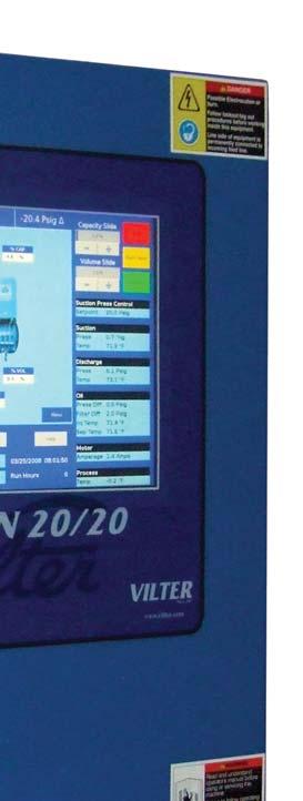
4 2.0 Vission 20/20 Retrofit Instructions This procedure defines the steps required to replace a Vilter Keypad Microcontroller with the Vission 20/20 Microcontroller. 2. Removal Step. Safely shutdown and de-energize the compressor unit () and keypad microcontroller (2) adhering to safe practices including lock-out/tag-out procedures. Figure. VSS Compressor Unit with Keypad Microprocessor Step 2. Disconnect wiring from transducers. WARIG When handling microcontroller, use additional personnel or lifting device as required. Failure to comply may result in serious injury and/or damage to equipment. Step 3. With additional personnel or lifting device, remove hardware securing keypad microcontroller (2) to rails (4). Remove keypad mirocontroller. Step 4. OTE Some compressor units are equipped with transducers and RTDs, if equipped, continue to step 3. If not, continue to installation. Disconnect all associated pressure and temperature sensors from compressor unit () and existing block and bleed assembly (3), if present. Step 5. Remove the existing block and bleed assembly (3), if present. 4 ViSSion 20/20 Retrofit Instructions 3539SCRF

5 2.2 Installation OTE Torque all hardware according to torque table specifications, see Table. OTE Modification to rails may be required to support and properly align Vission 20/20 microcontroller and block and bleed assembly. Follow standard practices for weldment and fabrication procedures. Step 5. Install new block and bleed assembly (4) on rails (3). Figure 2. Block and Bleed Assembly WARIG When handling microcontroller, use additional personnel or lifting device as required. Failure to comply may result in serious injury and/or damage to equipment. Step 6. Step 7. OTE On smaller compressor units, ensure there is adequate clearance between Vission 20/20 microcontroller and volume slide actuator. Adjust location of microcontroller as required by modifying support structure. Make sure Vission 20/20 microcontroller will install onto existing rails. Measure mounting holes on rails (3) and Vission 20/20 microcontroller (6), taking into consideration dimension of mounting holes of vibration isolators (5). Modify structure of rails (3) if required. Follow standard welding and fabrication procedures. ViSSion 20/20 Retrofit Instructions 3539SCRF 5


6 Step 8. Install hardware to secure new vibration isolators (5) to mounting holes of Vission 20/20 microcontroller (6). Figure 3. Vission 20/20 with Vibration Isolators Step 0. With additional personnel or lifting device, install hardware to secure Vission 20/20 microcontroller (6) with vibration isolators (5) to rails (3). OTE Ensure to use correct transducers because transducers have different pressure ranges. Suction manifold uses psia transducer, discharge manifold and oil filter inlet uses psia transducer. Step 9. Install transducers (7) on block and bleed assembly (4). Figure 4. Block and Bleed Assembly with Transducers 6 ViSSion 20/20 Retrofit Instructions 3539SCRF


 on suction manifold (9),")
 or oil manifold (3), if equipped.")
7 OTE Stainless steel tubing is not provided in a retrofit kit. Step 0. Route stainless steel tubing from suction manifold, discharge manifold and oil filter inlet lines. If existing tubing is not reusable then cables can be secured to block and bleed assembly (4). OTE Wells are also provided in retrofit kit. Install new wells as required. Step. Install RTDs (8) on suction manifold (9), discharge manifold (), oil separator (2) and inlet oil line (4) or oil manifold (3), if equipped. Step 2. Connect cables (0) to RTDs (8). Figure 5. Compressor Unit RTD Locations ViSSion 20/20 Retrofit Instructions 3539SCRF 7

. Figure 7.")
8 Step 2. Connect cables (0) to transducers (7). Figure 6. Block and Bleed Assembly with Transducers and Cables Step 3. Route cables (0) from RTDs (8) and transducers (7) through bottom right side of Vission 20/20 microcontroller (6). Figure 7. RTD and Transducer Cable Routing 8 ViSSion 20/20 Retrofit Instructions 3539SCRF


 shall be connected to 5-amp circuit breaker, CB.")
9 CAUTIO Do not route A/C and D/C wires together, this will cause Electromagnetic Interferance. Failure to comply may result in damage to equipment. Step 4. If equipped with solenoids (5) (i.e. Danfoss Motorized Valve), route cables (6) from solenoids through bottom left side of Vission 20/20 microcontroller (6). Figure 8. Solenoid Cable Routing Step 5. To make following connections according to supplied wiring diagram, refer to Section 3.0 Field Wiring Instructions. 3.0 Field Wiring Instructions OTE This procedure defines steps required to wire Vission 20/20 microcontroller for the following items: Compressor Motor Starter Auxiliary Contact, High Level Shutdown, Oil Separator Heater(s), Oil Pump Start and Compressor Starter. General figures, Figures 9, 0 and are used for purposes of explanation, follow supplied wiring diagram for detailed wiring. Step. Control power of 5 VAC 50/60 HZ must be wired to left side of terminal blocks inside the Vission 20/20 cabinet. Line power (A) shall be connected to 5-amp circuit breaker, CB. eutral () is connected to any terminal blocks. umber of line power feeds required to panel is dependent upon number supplied on compressor. Line power feeds for oil heaters are brought to additional 5-amp circuit breakers, CB2A, CB2B, CB2C and CB2D. eutrals for circuits (2, 3, 4, and 5) are connected to terminal blocks labeled HT2, HT3, HT4, and HT5. Units with V-PLUS oil cooling, L must connected to fuse in V-PLUS panel, and LA must be connected to terminal 2B. ViSSion 20/20 Retrofit Instructions 3539SCRF 9
10 VISSIO 2020 O COMPRESSOR SKID CB #2AWG THH (MIIMUM) CUSTOMER MCC PAEL (REFERECE MCC OR STARTER DRAWIG FOR DETAILED WIRIG) CUSTOMER SUPPLIED VISSIO POWER CIRCUIT TB-A TB- VISSIO 20/20 POWER AUX MS COMPRESSOR MOTOR STARTER AUX COTACT TB- TB-3 TB-8 TB-4 COMPRESSOR MOTOR STARTER AUX COTACT COMPRESSOR START TB- TB- COMPRESSOR START COMMAD OIL PUMP START TB-2 TB-2 OIL PUMP START COMMAD OIL SEPARATOR HEATER START TB-7 TB-7 OIL SEPARATOR HEATER START COMMAD Figure 9. MCC and Customer Control Center Interconnect Wiring Step 2. An auxiliary contact from compressor motor starter is required. Connect isolated contact to terminal blocks and 3. CB 2 5 AMPS A SW E-STOP EMI FILTER COTROL POWER DISCOECT AD BRACH CIRCUIT PROTECTIO TO BE SIZED PER THE ATIOAL ELECTRIC CODE. ICOMIG POWER SUPPLIED FROM REMOTE CUSTOMER SUPPLIED UL LISTED FUSED DISCOECT OR BREAKER B LIE LOAD C 2 5VAC / 60HZ GD IPUT RD- 35-A OUTPUT +5VDC +2VDC 5/2 COM TO CPU BASEBOARD GD DC POWER SUPPLIES GD DOOR GD LUG FROM LIE 3 FROM LIE 3 AUX MS HL SHUTDOW AUX LOW OIL LEVEL LS IPUTS DIGITAL IPUT: BOARD #3 PLUG X COMPRESSOR MOTOR STARTER AUXILIARY COTACT HIGH LEVEL SHUTDOW OPTIOAL OIL LEVEL FLOAT SWITCH # OPTIOAL OIL LEVEL FLOAT SWITCH #2 6 IPUT RS OUTPUT +24VDC 24 COM IPUTS DIGITAL OUTPUT: BOARD # PLUG X OUTPUTS H A 2A 3 4 CR CMP CR OP A BLUE *SEE OTE 0 BLACK BROW COMPRESSOR STARTER 70 OIL PUMP STARTER 73 CAPACITY ICREASE/DECREASE ACTUATOR DIGITAL IPUT: BOARD #3 PLUG X2 OPTIOAL CAPACITY COTROL SELECT /2 OPTIOAL REMOTE START/STOP OPTIOAL REMOTE CAPACITY ICREASE OPTIOAL REMOTE CAPAPCITY DECREASE 4 OUTPUTS 47 5 H DIGITAL OUTPUT: BOARD # PLUG X BLUE A2 *SEE OTE 0 BLACK A CRH A2 OUTPUT CA ALSO BE USED WITH A IDICATIG LIGHT, HOR, OR PLC IPUT (CUSTOMER SUPPLIED) H BROW VOLUME ICREASE/DECREASE ACTUATOR OIL SEPARATOR HEATER START 74, 78 OPTIOAL TRIP IDICATIO Figure 0. Vission 20/20 Mircocontroller Diagram Step 3. A dry contact from control relay CR must be wired to compressor motor starter coil. This dry contact is wired to terminal blocks according to supplied drawing. Control power for this coil should come from a source, which will be de-energized with compressor disconnect. 0 ViSSion 20/20 Retrofit Instructions 3539SCRF
11 GD GD GD HT- HT-2 B CB 5A 5A C4 OPE C X X2 X3 X4 X5 X X2 X3 X4 X5 Step 4. Step 5. A dry contact from control relay CR2 must be wired to oil pump motor starter coil. This dry contact is wired to two terminal blocks according to supplied drawing. Control power for this coil should come from a source, which will be de-energized with compressor disconnect. An auxiliary safety cutout is available to shut down compressor package. A dry contact must be supplied and wired to terminal blocks and 32. The jumper installed on terminal blocks must be removed to use this cutout. If contact is closed, it will allow compressor to run. If contact opens at any time, compressor will shut down. CB 2C 5A GD GD GD HT- HT-2 B CB 5A 2C CB CB 2C 5A 5A CUSTOMER DIGITAL WIRIG CB 2C 5A 2C CB CB 2C 5A DIGITAL WIRIG DIGITAL IPUT BOARD #3 DIGITAL OUTPUT BOARD #2 DIGITAL OUTPUT BOARD # AALOG IPUT BOARD #7 AALOG IPUT BOARD #6 AALOG OUTPUT BOARD #0 CUSTOMER AALOG WIRIG Figure. Vission 20/20 Terminal Blocks Step 6. Step 7. Indication of compressor shutdown status is also available. There is an output on terminal blocks 8 and where a relay coil can be wired. For output, an energized state represents a safe condition. A deenergized state indicates a loss of voltage to relay coil or a failure has occurred. Current transformer supplied in compressor motor conduit box should be checked to insure that motor leads of one leg are pulled through the transformer. ote, there is a dot on one side of the current transformer. This dot must face away from the motor. Typically, a wye delta started motor should have leads and 6 pulled through this transformer for a 6 lead motor. However, this should always be checked as different motors and starting methods will require different leads to be used. ViSSion 20/20 Retrofit Instructions 3539SCRF
12 Type Bolt SAE Grade 2 Coarse (UC) Head Markings Table. Torque Specifications Torque Specifications (ft-lbs) ominal Size umbers or Inches #0 /4 5/6 3/8 7/6 /2 9/6 5/8 3/4 7/ * SAE Grade 5 Coarse (UC) SAE Grade 5 Coarse (UC) SAE Grade 8 Coarse (UF) Socket Head Cap Screw (ASTM A574) Coarse (UC) ) Torque values in this table are not to override other specific torque specifications when supplied. 2) When using loctite, torque values in this table are only accurate if bolts are tightened immediately after loctite is applied. * The proof strength of Grade 2 bolts is less for sizes 7/8 and above and therefore the torque values are less than smaller sizes of the same grade. Torque Specifications for 7-4 Stainless Steel Fasteners (ft-lbs) Type Bolt/ut Head Markings ominal Size umbers or Inches #0 /4 5/6 3/8 7/6 /2 9/6 5/8 3/4 Hex & Socket Head Cap Screws ut OTE: Continue use of red loctite #27 (VP 2205E) on currently applied locations. Use blue loctite #243 (VP 2205F or 2205G) on all remaining locations. 2 ViSSion 20/20 Retrofit Instructions 3539SCRF
13
14 3539SCRF Rev. (4/3) Emerson and Vilter are trademarks of Emerson Electric Co. or one of its affiliated companies. 202 Emerson Climate Technologies, Inc. All rights reserved. Printed in the USA.
Vission 20/20 micro-controller. Operation and service manual Version 2.6
 Vission 20/20 micro-controller Operation and service manual Version 2.6 Important Message READ CAREFULLY BEFORE OPERATING YOUR COMPRESSOR. The following instructions have been prepared to assist in operation
Vission 20/20 micro-controller. Operation and service manual
 Vission 20/20 micro-controller Operation and service manual Section Title Table of Contents Section Number How To Use This Manual...TOC-8 Section 1 Operational Flow Charts Requirements to Start Compressor...1-1
CHILLER MODEL NO. YS SOLID STATE STARTER, MODEL NO. SSS, L B OPTIONAL FACTORY INSTALLED DISCONNECT SWITCH AMPS OR
 WIRING DIAGRAMS CONTRACTOR ORDER NO. JCI CONTRACT NO. JCI ORDER NO. Supersedes: 160.80-PW4 (1099) Form: 160.80-PW4 (215) FIELD CONNECTIONS ROTARY SCREW CHILLER WITH GRAPHIC CONTROL CENTER AND YORK MOD
Application Engineering
 Application Engineering February, 2009 Copeland Digital Compressor Controller Introduction The Digital Compressor Controller is the electronics interface between the Copeland Scroll Digital Compressor
SIGNAL WORDS QUALIFIED PERSON
 SIGNAL WORDS The signal words Danger, Warning and Caution used in this manual indicate the degree of hazard that may be encountered by the user. These words are defined as: Danger - Indicates death or
Kit Drain Water Tempering Kit
 Kit 90092 - Drain Water Tempering Kit for Models DH2000 and MD2000 Kit Parts: Refer to the parts list below to ensure all the parts necessary for the installation are in your kit. Item Part Description
Application Engineering
 Application Engineering March 2011 Copeland Digital Compressor Controller Introduction The Digital Compressor Controller is the electronics interface between the Copeland Scroll Digital compressor or the
Control Panel. Operation and Service Manual
 Control Panel Operation and Service Manual 1 2 Important Note Before applying power to the control panel, all wiring to the panel should be per NEC. Specifically check for proper voltage and that the neutral
331-SV. User Manual THREE PHASE DUPLEX LIFT STATION CONTROL PANEL WITH STATIONVIEW CONTROLLER. Ashland, OH
 331-SV User Manual THREE PHASE DUPLEX LIFT STATION CONTROL PANEL WITH STATIONVIEW CONTROLLER Ashland, OH 800-363-5842 WWW.PRIMEXCONTROLS.COM Warranty void if panel is modified. Call factory with servicing
Wiring Diagrams DIAGRAM INDEX
 30HK040-060;30HL050,060;30HW018-040 Reciprocating Liquid Chillers with ComfortLink Controls 50/60 Hz Wiring Diagrams DIAGRAM INDEX UNIT 30 VOLTAGE DIAGRAM TYPE FIGURE LABEL DIAGRAM All Component Arrangement
Sentinel Field Satellite Controller
 WARNING HIGH VOLTAGE 115V M AP Sentinel Field Satellite Controller Installation Instructions Important: For your protection and the safety of the product user, please comply with all Caution and Warning
Water to Water Geothermal Heat Pump 3-Phase Models Both 208 & 480
 Installer Water to Water Geothermal Heat Pump 3-Phase s Both 208 & 480 Installation Instructions : THA-***-2 (208, 3-Phase) THT-***-2 (208, 3-Phase) THA-***-3 (480, 3-Phase) THT-***-3 (480, 3-Phase) This
ACSI MODEL 1406BB-04-AO POWER SUPPLY INSTALLATION INSTRUCTIONS
 II 1400-10 ACSI MODEL 1406BB-04-AO POWER SUPPLY INSTALLATION INSTRUCTIONS Features: Up to 1.95 Amps Load Capacity Class 2 Rated Outputs Overload, Over Voltage, and Short Circuit Protection Standby Battery
Aldi V4 & V V1.1 5/23/2014
 Aldi V4 & V5 2012 2013 V1.1 5/23/2014 Aldi Control Techniques SK Series VFD & Hussmann MX Series MicroChannel Condenser Equipment Operation Component Orientation Control Wiring Programming and Start Up
FIELD CONNECTIONS FOR YK CHILLER (STYLE G) OPTIVIEW CONTROL CENTER WITH REMOTE MEDIUM VOLTAGE SSS
 OPTIVIEW CONTROL CENTER WITH REMOTE MEDIUM VOLTAGE SSS") Supersedes: 160.75-PW2 (508) Form 160.75-PW2 (311) FIELD CONNECTIONS FOR YK CHILLER (STYLE G) OPTIVIEW CONTROL CENTER WITH REMOTE MEDIUM VOLTAGE SSS WIRING DIAGRAM CONTRACTOR ORDER NO. YORK CONTRACT NO.
Supersedes: 160.75-PW2 (508) Form 160.75-PW2 (311) FIELD CONNECTIONS FOR YK CHILLER (STYLE G) OPTIVIEW CONTROL CENTER WITH REMOTE MEDIUM VOLTAGE SSS WIRING DIAGRAM CONTRACTOR ORDER NO. YORK CONTRACT NO.
Solenoid Valve Output Module IC693MDL760 Product Description
 GFK-A November 000 Solenoid Valve Output Module ICMDL0 Product Description Description This ICMDL0 output module provides eleven pneumatic outputs and five VDC sourcing outputs. For each pneumatic output,
Internal wiring that is not field terminated may be white in color.
 ....... Safety Procedures WARIG Dangerous environment. Highly flammable/explosive fuels and high voltage are present. Failure to observe all safety precautions could result in serious injury or death.
ARCHITECTURAL CONTROL SYSTEMS, INCORPORATED ST. LOUIS, MISSOURI
 II 1400-6 ARCHITECTURAL CONTROL SYSTEMS, INCORPORATED ST. LOUIS, MISSOURI ACSI 1426-04-AO ELECTRIC LATCH RETRACTION CONTROLLER INSTALLATION INSTRUCTIONS I.D. 1092, REV. C INSTALLATION For C-UL Listed applications,
ACR RECESSED AIRCURTAIN ELECTRICALLY HEATED, AMBIENT & LPHW INSTALLATION AND OPERATING MANUAL
 Instruction Manual. ACR RECESSED AIRCURTAI ELECTRICALLY HEATED, AMBIET & LPHW ISTALLATIO AD OPERATIG MAUAL IDEX Section General information ----------------------------------------------------------- 1
UL/NEMA Type 1 & Type 12 FRENIC-HVAC Combination VFD
 UL/NEMA Type 1 & Type 12 FRENIC-HVAC Combination VFD Safety Precautions Read this manual thoroughly before proceeding with installation, connections (wiring), or maintenance and inspection. Ensure you
SERIES 73 ELECTRIC ACTUATOR OPERATION AND MAINTENANCE MANUAL. The High Performance Company
 SERIES 73 ELECTRIC ACTUATOR OPERATION AND MAINTENANCE MANUAL The High Performance Company Table Of Contents: page Safety instructions: Definitions of Terms... 2 Introduction principle of operation...
MODELS YCRL0064, 0074, 0084, 0096, 0118, 0126, 0156, 0177, 0198, 0200, 0230, 0260, 0300, 0345, 0385, 0445, 0530 and YCRL0610 STYLE "A"
 WATER-COOLED LIQUID CHILLERS HERMETIC SCROLL RENEWAL PARTS Supercedes: 150.7-RP1 (709) Form: 150.7-RP1 (810) MODELS YCRL0064, 0074, 0084, 0096, 0118, 016, 0156, 0177, 0198, 000, 030, 060, 0300, 0345, 0385,
Continuing Education Course #206 Introduction to Designing Machine Control Systems Part 2
 1 of 5 Continuing Education Course #206 Introduction to Designing Machine Control Systems Part 2 1. Continuing to answer the following questions indicates that you understands that the presented material
PRODUCT DRAWING WIRING DIAGRAM FIELD CONNECTIONS MILLENNIUM MODEL YT CHILLERS (STYLE J) WITH ELECTRO-MECHANICAL STARTER JOB DATA:
 WITH ELECTRO-MECHANICAL STARTER JOB DATA:") Supersedes: 160.55-PW4 (1199) FORM 160.55-PW4 (600) PRODUCT DRAWING YORK INTERNATIONAL CORPORATION P.O. Box 1592, YORK, PA 17405 CONTRACTOR ORDER NO. YORK CONTRACT NO. YORK ORDER NO. WIRING DIAGRAM FIELD
Supersedes: 160.55-PW4 (1199) FORM 160.55-PW4 (600) PRODUCT DRAWING YORK INTERNATIONAL CORPORATION P.O. Box 1592, YORK, PA 17405 CONTRACTOR ORDER NO. YORK CONTRACT NO. YORK ORDER NO. WIRING DIAGRAM FIELD
Installation Instructions
 08A0, 09A0, 08A00, 08A00 For Use With Horizontal EconoMi$ert IV or EconoMi$ert Only SMALL ROOFTOP UNITS ACCESSORY HORIZONTAL EXHAUST GAS HEATING/ELECTRIC COOLING, ELECTRIC COOLING, AND HEAT PUMP UNITS
AF40... AF96 3-pole contactors Technical data
 Main pole - Utilization characteristics according to IEC Standards IEC 60947- / 60947-4- and EN 60947- / 60947-4- Rated operational voltage Ue max. 690 V Rated frequency (without derating) 50 / 60 Hz Conventional
3143 Production Drive Fairfeild, Ohio Model HA Installation and Service Manual
 3143 Production Drive Fairfeild, Ohio 45014 513-874-3733 Model HA-1000 Installation and Service Manual 3143 Production Drive Fairfeild, Ohio 45014 513-874-3733 Model HA-1000 Installation and Service Manual
Matrix AP 400V 690V INSTALLATION GUIDE. Quick Reference. ❶ How to Install Pages 6 20 ❷ Startup/Troubleshooting Pages WARNING
 Matrix AP 400V 690V INSTALLATION GUIDE FORM: MAP-IG-E REL. May 2017 REV. 002 2017 MTE Corporation WARNING High Voltage! Only a qualified electrician can carry out the electrical installation of this filter.
Dynamic Braking Kit for FlexPak 3000 and WebPak 3000 Digital DC Drives 1.5 HP to VAC, 3 HP to VAC without NEMA1 Enclosures
 Dynamic Braking Kit for FlexPak 3000 and WebPak 3000 Digital DC Drives 1.5 HP to 150 HP @ 230 VAC, 3 HP to 600 HP @ 460 VAC without NEA1 Enclosures odel Numbers 912FKxxxx and 913FKxxxx Instruction anual
3143 Production Drive Fairfeild, Ohio Model HA-45. Installation and Service Manual
 3143 Production DriveFairfeild, Ohio 45014513-874-3733 Model HA-45 Installation and Service Manual 3143 Production DriveFairfeild, Ohio 45014513-874-3733 Model HA-45 Installation and Service Manual Table
Installation Instructions
 CRPWREXH08A0, CRPWREXH09A0, CRPWREXH08A00, CRPWREXH08A00 For Use With Horizontal EconoMi$er IV, EconoMi$er, or EconoMi$er X (W70) Installation Instructions TABLE OF CONTENTS PACKAGE CONTENTS... PACKAGE
RETROFIT CONVERSION TO THE FRICK QUANTUM LX CONTROL INSTALLATION INSTRUCTIONS
 S90-120 I/OCT 2004 File: SERVICE MANUAL - Section 90 Replaces: S90-120 I/OCT 99 Dist: 3, 3a, 3b, 3c RETROFIT CONVERSION TO THE FRICK QUANTUM LX S90-120 I Page 2 FRICK QUANTUM LX RETROFIT FRICK QUANTUM
This document describes the commissioning checklist procedures for the Capstone MicroTurbine systems.
 Capstone Capstone Turbine Corporation 21211 Nordhoff Street Chatsworth CA 91311 USA Telephone: (818) 734-5300 Facsimile: (818) 734-5320 Website: www.microturbine.com Work Instructions Commissioning Checklist
SAVE THESE INSTRUCTIONS
 READ AND FOLLOW ALL SAFETY INSTRUCTIONS! SAVE THESE INSTRUCTIONS AND DELIVER TO OWNER AFTER INSTALLATION IMPORTANT SAFEGUARDS When using electrical equipment, basic safety precautions should always be
I-BFV.KIT Butterfly Valve Gear Operator Replacement
 SERIES 5, 05,, and 0C WARNING Read and understand all instructions before attempting to install, remove, adjust, or maintain any Victaulic piping products. Depressurize and drain the piping system before
ELECTRICAL SYSTEM RP-7
 ELECTRICAL SYSTEM RP-7 This section of the manual does not include integral electrical components of the engine. Refer to section Engine RP-1 for details. This section of the manual is divided into three
YCAS AIR-COOLED LIQUID CHILLERS YCAS0373 THROUGH YCAS0653 STYLE G (R22) (50 Hz)
 (50 Hz)") AIR-COOLED SCREW LIQUID CHILLERS WIRING DIAGRAM New Release Form 201.19-W3 (1104) YCAS AIR-COOLED LIQUID CHILLERS YCAS0373 THROUGH YCAS0653 STYLE G (R22) (50 Hz) TABLE OF CONTENTS PAGE NOMENCLATURE...
AIR-COOLED SCREW LIQUID CHILLERS WIRING DIAGRAM New Release Form 201.19-W3 (1104) YCAS AIR-COOLED LIQUID CHILLERS YCAS0373 THROUGH YCAS0653 STYLE G (R22) (50 Hz) TABLE OF CONTENTS PAGE NOMENCLATURE...
RETROFIT CONVERSION TO THE VILTER SINGLE SCREW INSTALLATION INSTRUCTIONS. Contents
 Form 090.040-I02 (JAN 2018) INSTALLATION File: SERVICE MANUAL - Section 90 Replaces: 090.040-I02 (JUL 2017) Dist: 3, 3a, 3b, 3c RETROFIT CONVERSION TO THE FRICK QUANTUM HD CONTROL VILTER SINGLE SCREW Contents
INSTALLATION MANUAL ACL 5500 COMBUSTION SAFETY CONTROLLER
 5500 COMBUSTION SAFETY CONTROL INSTALLATION MANUAL FOR 5500 COMBUSTION SAFETY CONTROLLER WARNING This manual must be read in its entirety before installation of this controller. Installation must be performed
Copeland Screw Compressors Semi-Hermetic Compact Operating Instructions
 Copeland Screw Compressors Semi-Hermetic Compact Operating Instructions SCH2 & SCA2 High Temperature Compressors 35-240 Horsepower 1. Introduction This series of semi-hermetic compact screw compressors
Installation Instructions
 CRLOWAMB039A00 CRLOWAMB040A00 CRTRXKIT002A00 ACCESSORY MOTORMASTER I HEAD PRESSURE CONTROL KIT 12.5 TON HEAT PUMP Installation Instructions TABLE OF CONTENTS PACKAGE CONTENTS... 1 PRODUCT USAGE... 2 SAFETY
BITZER Liquid Injection Guidelines for CSH Compressors
 BITZER Liquid Injection Guidelines for CSH Compressors Liquid Injection Additional cooling may be required during reduced capacity operation, high condensing and / or low evaporating temperatures. Direct
Precision Power Center INSTALLATION, OPERATION, & MAINTENANCE MANUAL
 POWER CONVERSION/DISTRIBUTION Precision Power Center INSTALLATION, OPERATION, & MAINTENANCE MANUAL 3 Phase 15 kva - 225 kva 50 & 60 Hz TABLE OF CONTENTS IMPORTANT SAFETY INSTRUCTIONS................................................1
Factory Sealed Panelboards
 FACTORY SEALED PAELBOARDS Factory Sealed Designed for use In Class I, Division 2 and Class I, Zone 2 areas such as petroleum refineries, chemical or petrochemical facilities, the factory sealed panelboards
Installation Instructions
 00A0, 0A0-0A0 080A00 08A00 For Use With Vertical EconoMi$ert IV or EconoMi$ert Only SMALL ROOFTOP UNITS ACCESSORY VERTICAL EXHAUST GAS HEATING/ELECTRIC COOLING, ELECTRIC COOLING, AND HEAT PUMP UNITS TO5TON
Users Manual. Defender 1 8.0KW to 14.0KW Online Emergency Lighting Inverter. Technical Manual # Revision B
 Users Manual Defender 1 8.0KW to 14.0KW Online Lighting Inverter Technical Manual #018-0102-01 Revision B Phone: 1.877.DSPM.POWER 1.877.377.6769 Fax: 909.930.3335 Website: www.dspmanufacturing.com E-Mail:
Users Manual. Cobra Plus Stand-By Emergency Lighting Inverter. Technical Manual # Revision B
 Users Manual Cobra Plus Stand-By Lighting Inverter Technical Manual #018-0110-01 Revision B Phone: 1.877.DSPM.POWER 1.877.377.6769 Fax: 909.930.3335 Website: www.dspmanufacturing.com E-Mail: techsupport@dspmanufacturing.com
LIEBERT APM 3-PHASE UPS: 15-90KVA/KW, 60HZ, VAC, SINGLE & DUAL INPUT - SITE PLANNING DATA
 LIEBERT APM 3-PHASE UPS: 15-90KVA/KW, 60HZ, 208-600VAC, SINGLE & DUAL INPUT - SITE PLANNING DATA BYPASS DISTRIBUTION CABINET (Optional; see Note 7) The UPS must be fed from a solidly grounded wye or delta
GES-TN11-Series UPS External Wrap Around Bypass System. Operators Manual. M0403_TN_Series_Ext_Bypass_Manual V
 GES-T11-Series External Wrap Around Bypass System Operators Manual M43_T_Series_Ext_Bypass_Manual V1.7 212-6-12 M43_T_Series_Ext_Bypass_Manual V1.7 212-6-12 ote The instructions contained in this manual
SAVE THESE INSTRUCTIONS
 READ AND FOLLOW ALL SAFETY INSTRUCTIS! SAVE THESE INSTRUCTIS AND DELIVER TO OWNER AFTER INSTALLATI IMPORTANT SAFEGUARDS! When using electrical equipment, basic safety precautions should always be followed
R & D SPECIALTIES ROTROL I USER'S MANUAL
 R & D SPECIALTIES ROTROL I USER'S MANUAL TABLE OF CONTENTS INTRODUCTION...2 SPECIFICATIONS...2 CONTROLS AND INDICATORS...3 TIME DELAYS...4 INSTALLATION...5 SYSTEM OPERATION...9 TROUBLESHOOTING...13 OPTIONAL
Induction Power Supplies
 Induction Power Supplies 7.5kW; 135 400kHz 480V version (Integral Heat Station) User s Guide Model 7.5-135/400-3-480 SMD Control Brds Rev. D 5/08 Table of Contents 1. Specifications and features...3 2.
FM200 FLOW/NO-FLOW MONITOR INSTALLATION AND TECHNICAL MANUAL 120 VAC MODEL 6/1/2017
 FM200 FLOW/NO-FLOW MONITOR INSTALLATION AND TECHNICAL MANUAL 120 VAC MODEL 6/1/2017 Maxi-Tronic, Inc. 417 Wards Corner Road Loveland, OH 45140 513.398.2500 800.659.8250 FAX: 513.398.2536 info@maxitronic.com
FIELD CONNECTIONS MODEL YK CHILLERS (STYLE F AND G) WITH VARIABLE SPEED DRIVE
 WITH VARIABLE SPEED DRIVE") Supersedes: 160.54-PW6 (513) Form 160.54-PW6 (816) WIRING DIAGRAM CONTRACTOR ORDER NO. YORK CONTRACT NO. YORK ORDER NO. FIELD CONNECTIONS MODEL YK CHILLERS (STYLE F AND G) WITH VARIABLE SPEED DRIVE PURCHASER
Supersedes: 160.54-PW6 (513) Form 160.54-PW6 (816) WIRING DIAGRAM CONTRACTOR ORDER NO. YORK CONTRACT NO. YORK ORDER NO. FIELD CONNECTIONS MODEL YK CHILLERS (STYLE F AND G) WITH VARIABLE SPEED DRIVE PURCHASER
Series BFM Bulk Flow Monitor 1A FUSE RED LED RELAY. Part Number BFM-1 BFM-2 BFM-3 BFS-1
 Series Bulk Flow Monitor Specifications - Installation and Operating Instructions Bulletin FL-1-4x 3/4 CONDUIT KNOCKOUTS BFS 1A FUSE RED LED RELAY 5-9/64 [130.45] TRANSFORMER 3[76.20] GREEN LED 7 [177.80]
Catalog Number Identification with Elements Explained
 Installation Manual 920 Remote Control Switches 30 through 225 ampere sizes This Installation! Manual is for green nameplate ASCO 920s only. For black nameplate ASCO 920s refer to Owners Manual 2D4920
BATTERY SAVER LOW RIPPLE HO
 INSTRUCTION MANUAL BATTERY SAVER LOW RIPPLE HO LOW RIPPLE POWER SUPPLY / AUTOMATIC LOAD SWITCH FOR 12VDC VEHICLE SYSTEMS MODEL #: 091-195-12 INPUT: 120 Volt, 50/60 Hz, 4.5 Amps RMS OUTPUT: 13.2 Volts DC,
32XR. 3 Phase Duplex Pump Control Panel (Level Transmitter Based) Quick Start Guide
 Quick Start Guide") 32XR 3 Phase Duplex Pump Control Panel (Level Transmitter Based) Quick Start Guide RED ALARM LIGHT LEVEL CONTROLLER H-O-A SWITCHES HORN SILENCE INNER DOOR MOTOR STARTERS WITH INTERCHANGEABLE OVERLOAD MODULES
32XR 3 Phase Duplex Pump Control Panel (Level Transmitter Based) Quick Start Guide RED ALARM LIGHT LEVEL CONTROLLER H-O-A SWITCHES HORN SILENCE INNER DOOR MOTOR STARTERS WITH INTERCHANGEABLE OVERLOAD MODULES
ACCUVALVE MODEL AVC6000 SUBMITTAL MATERIALS MODEL CODE. AccuValve Model AVC6000 AVC6 - - DWG. NO: REVISION: REV. DATE:
 ACCUVALVE MODEL AVC6000 SUBMITTAL MODEL CODE WARNING: NOT FOR USE WITH PERCHLORIC ACID MATERIALS VALVE HOUSING MATERIAL 2 = 304SS, 20 GAUGE 3 = 316SS, 20 GAUGE 4 = ALUMINUM, 16 GAUGE 6 = HIGH TEMP 304SS,
PEC 827E. 120 VAC AC Distribution Shelf. Critical Power Product Manual
 Critical Power Product Manual PEC 827E 120 VAC AC Distribution Shelf 6180498P (23 For Conduit), 6180529P (23 W/Outlets) 6180542P (19 For Conduit), 6180533P (19 W/Outlets) This document issue 4ge is updated
Installation. Part A, Section 3. This section covers the following unit configurations. Voltage 1, 2, 3. Vista Standard (V) A3EN-04-[3V-A-AAXV]-11
![Installation. Part A, Section 3. This section covers the following unit configurations. Voltage 1, 2, 3. Vista Standard (V) A3EN-04-[3V-A-AAXV]-11](/thumbs/87/95082297.jpg "Installation. Part A, Section 3. This section covers the following unit configurations. Voltage 1, 2, 3. Vista Standard (V) A3EN-04-[3V-A-AAXV]-11") Part A, Section 3 This section covers the following unit configurations. Model All Voltage 1, 2, 3 Pump All Manifold All Control Vista Standard (V) A 3-0 A 3-1 Section A 3 WARNING: Allow only qualified
Part A, Section 3 This section covers the following unit configurations. Model All Voltage 1, 2, 3 Pump All Manifold All Control Vista Standard (V) A 3-0 A 3-1 Section A 3 WARNING: Allow only qualified
DIESEL Engine Fire Pump Controllers Features
 1-1 Printer / Recorder The industrial grade thermal printer is housed in a rugged steel enclosure within the controller. The on/off switch, feed and reset buttons are front accessible. A bi-color status
Connect Series Accessories
 Connect Series Accessories 2015 Cummins Power Generation Inc. All rights reserved. Specifications are subject to change without notice. Cummins Power Generation and Cummins are registered trademarks of
ACC Series Power Conditioner OPERATION & INSTALLATION MANUAL
 ACC Series Power Conditioner OPERATION & INSTALLATION MANUAL PHASETEC digital power conditioners are designed to safely operate electrical equipment in the harshest power quality environments. With a wide
AF series contactors (9 2650)
") R E32527 R E39322 contactors General purpose and motor applications AF series contactors (9 2650) 3- & 4-pole contactors General purpose up to 2700 A Motor applications up to 50 hp, 900 kw NEMA Sizes 00
R E32527 R E39322 contactors General purpose and motor applications AF series contactors (9 2650) 3- & 4-pole contactors General purpose up to 2700 A Motor applications up to 50 hp, 900 kw NEMA Sizes 00
SECTION MOTOR CONTROL
 SECTION 26 24 19 MOTOR CONTROL PART 1 - GENERAL 1.1 SECTION INCLUDES A. Manual motor starters B. Magnetic motor starters C. Combination magnetic motor starters D. Solid-state reduced voltage motor starters
- Wiring Brochure Zone Manager 336
 - Wiring Brochure W 336 12/08 1 Information Brochure Choose controls to match application Application Brochure Design your mechanical applications 2 3 Rough-in Wiring Rough-in 4 Wiring Brochure Wiring
User s Manual. ACS550-CC Packaged Drive with Bypass Supplement for ACS550-01/U1 Drives User s Manual
 User s Manual ACS550-CC Packaged Drive with Bypass Supplement for ACS550-01/U1 Drives User s Manual ii ACS550-CC Packaged Drive with Bypass ACS550 Drive Manuals GENERAL MANUALS ACS550-01/U1 Drives User's
Connect Series Accessories
 Connect Series Accessories CONNECT SERIES ACCESSORIES Table of Contents ALTERNATOR HEATERS... 1 ANNUNCIATORS... 2 AUXILIARY... 3 AUXILIARY CONFIGURABLE SIGNAL INPUTS / RELAY OUTPUTS... 3 AUXILIARY OUTPUTS
R820 REV2 SERIES SCR POWER CONTROLS NOVEMBER 2017
 R80 REV SERIES SCR POWER CONTROLS NOVEMBER 017 Product overview The Viconics R80 series SCR power controls are designed for cost effective, precise modulation of electric loads for most electric heating
WIRING DIAGRAM MODEL YK (STYLE G) LIQUID CHILLERS OPTIVIEW CONTROL CENTER WITH ELECTRO-MECHANICAL STARTER
 LIQUID CHILLERS OPTIVIEW CONTROL CENTER WITH ELECTRO-MECHANICAL STARTER") PRODUCT DRAWING Supercedes Form 160.75-PW5 (311) Form 160.75-PW5 (1013) WIRING DIAGRAM MODEL YK (STYLE G) LIQUID CHILLERS OPTIVIEW CONTROL CENTER WITH ELECTRO-MECHANICAL STARTER CONTRACTOR PURCHASER ORDER
PRODUCT DRAWING Supercedes Form 160.75-PW5 (311) Form 160.75-PW5 (1013) WIRING DIAGRAM MODEL YK (STYLE G) LIQUID CHILLERS OPTIVIEW CONTROL CENTER WITH ELECTRO-MECHANICAL STARTER CONTRACTOR PURCHASER ORDER
Florham Park, NJ USA Call (ASCO) for sales or service
 for sales or service") Operator s Manual 4000 Series ATS Automatic Open-Transition Transfer Switches D design 30 230A, J design 260 600A, H-design 800 1200A, G-design 1600 4000A, F-design 4000A DANGER is used in this manual
Operator s Manual 4000 Series ATS Automatic Open-Transition Transfer Switches D design 30 230A, J design 260 600A, H-design 800 1200A, G-design 1600 4000A, F-design 4000A DANGER is used in this manual
VARNA Products 15 GPM (57 LPM) Prelube Kit for MTU 4000 Series Marine Engines
 Prelube Kit for MTU 4000 Series Marine Engines") VARNA Products 15 GPM (57 LPM) Prelube Kit for MTU 4000 Series Marine Engines Installation and Users Manual For the following Prelube Kits: VARNA Products P/N 6423 Kit for 208 VAC 3 Phase VARNA Products
VARNA Products 15 GPM (57 LPM) Prelube Kit for MTU 4000 Series Marine Engines Installation and Users Manual For the following Prelube Kits: VARNA Products P/N 6423 Kit for 208 VAC 3 Phase VARNA Products
INSTALLATION INSTRUCTIONS FOR EGA AND EGH SERIES ELECTRIC HEATERS IN V OR H SERIES UNITS
 INSTALLATION INSTRUCTIONS FOR EGA AND EGH SERIES ELECTRIC HEATERS IN V OR H SERIES UNITS NOTE TO INSTALLER The words SHALL and MUST indicate a requirement which is essential to satisfactory and safe product
Installation Instructions
 NOTE: Read the entire instruction manual before starting the installation. This symbol indicates a change since the last issue. SAFETY CONSIDERATIONS Installing and servicing air conditioning equipment
Parts Catalog. Generator Set TGHAA (Spec A C) Printed in U.S.A. Replaces (Spec A) 1 97
 Printed in U.S.A. Replaces (Spec A) 1 97") Parts Catalog TGHAA Generator Set Printed in U.S.A. 9 00 (Spec A C) 9 Replaces 9 00 (Spec A) 97 To avoid errors or delay in filling your parts order, always give the MODEL, SPEC NO. and SERIAL NO. from
Parts Catalog TGHAA Generator Set Printed in U.S.A. 9 00 (Spec A C) 9 Replaces 9 00 (Spec A) 97 To avoid errors or delay in filling your parts order, always give the MODEL, SPEC NO. and SERIAL NO. from
Parts Manual. Transfer Switch. OTPCB (Spec A) 150/225/260 Amps. English Original Instructions (Issue 4)
 150/225/260 Amps. English Original Instructions (Issue 4)") Parts Manual Transfer Switch 50/225/260 Amps OTPCB (Spec A) English Original Instructions -203 962 0228 (Issue ) This catalog covers models produced under the Cummins /Onan and Cummins Power Generation
Parts Manual Transfer Switch 50/225/260 Amps OTPCB (Spec A) English Original Instructions -203 962 0228 (Issue ) This catalog covers models produced under the Cummins /Onan and Cummins Power Generation
User s Manual. ACS550-CC Packaged Drive with Bypass Supplement for ACS550-01/U1 Drives User s Manual
 User s Manual ACS550-CC Packaged Drive with Bypass Supplement for ACS550-01/U1 Drives User s Manual ii ACS550-CC Packaged Drive with Bypass ACS550 Drive Manuals GENERAL MANUALS ACS550-01/U1 Drives User's
Parts Manual. Transfer Switch. OTPCC (Spec A) 300/400/600 Amps. English Original Instructions (Issue 4)
 300/400/600 Amps. English Original Instructions (Issue 4)") Parts Manual Transfer Switch 00/00/600 Amps OTPCC (Spec A) English Original Instructions -20 962 0229 (Issue ) This catalog covers models produced under the Cummins /Onan and Cummins Power Generation brand
Parts Manual Transfer Switch 00/00/600 Amps OTPCC (Spec A) English Original Instructions -20 962 0229 (Issue ) This catalog covers models produced under the Cummins /Onan and Cummins Power Generation brand
ACCESSORY KIT INSTALLATION INSTRUCTIONS Low Ambient Accessory For Air Cooled Split System Air Conditioners HB 180/240, HF -15,-20 Models Only
 ACCESSORY KIT INSTALLATION INSTRUCTIONS Low Ambient Accessory For Air Cooled Split System Air Conditioners HB 180/240, HF -15,-20 Models Only GENERAL These split-system condensing units are designed to
Sec 3 TROUBLESHOOTING VARIABLE SPEED DRIVE ASC450 SOFTWARE
 Sec 3 Sec 1 Sec 2 Sec 3 Sec 4 Sec 5 Sec 6 Sec 7 Sec 8 Sec 9 Sec 10 OVERVIEW MOUTIG WIRIG PARAMETERS TROUBLESHOOTIG O2 TRIM VARIABLE SED DRIVE MODbus ASC450 SOFTWARE SCIFICATIOS Sec 3 Sec 1 Sec 2 Sec 3
RENEWAL PARTS Supersedes: RP4 (1012) Form RP4 (813)
 Form RP4 (813)") VARIABLE SPEED DRIVE RENEWAL PARTS Supersedes: 160.00-RP4 (1012) Form 160.00-RP4 (813) 292 HP 50 HZ, 400VAC (P/N 371-03700-XXX) 351 HP 60 HZ, 460VAC (P/N 371-02767-XXX) 419 HP 50 HZ, 400VAC (P/N 371-03789-XXX)
VARIABLE SPEED DRIVE RENEWAL PARTS Supersedes: 160.00-RP4 (1012) Form 160.00-RP4 (813) 292 HP 50 HZ, 400VAC (P/N 371-03700-XXX) 351 HP 60 HZ, 460VAC (P/N 371-02767-XXX) 419 HP 50 HZ, 400VAC (P/N 371-03789-XXX)
DIN Rail UPS Model: DIN-UPS 48-5 Installation/Operation Manual
 DI Rail US Model: DI-US 48-5 Installation/Operation Manual Table of Contents Section age Section age Quick Start 2 1) General Information 4 Materials rovided 4 Optional quipment 4 2) Safety Information
Nova UAC (NV-UAC-M) Modified Sine Wave 650W 800W 1000W
 Modified Sine Wave 650W 800W 1000W") ova UAC (V-UAC-M) Modified Sine Wave 650W 800W 1000W ISTRUCTIOS IMPORTAT SAFEGUARDS When using electrical equipment, basic safety precautions should always be followed including the following: 1. READ
ova UAC (V-UAC-M) Modified Sine Wave 650W 800W 1000W ISTRUCTIOS IMPORTAT SAFEGUARDS When using electrical equipment, basic safety precautions should always be followed including the following: 1. READ
Wiring Diagrams DIAGRAM INDEX. POWER SCHEMATICS Figure Number. Label Diagram No. 30HX ALL ALL
 Wiring Diagrams 30HXA, 30HXC Condenserless and Fluid-Cooled Chillers 50/60 Hz DIAGRAM INDEX POWER SCHEMATICS Unit 30HXA,C Voltage Figure Number Label Diagram No. 30HX 076-186 ALL 1 500141 206-271 ALL 2
ACCESSORY KIT INSTALLATION INSTRUCTIONS
 ACCESSORY KIT INSTALLATION INSTRUCTIONS Low Ambient Accessory For Air Cooled Split-System Air Conditioners YD360/480/600, YJ-30/-40/-50 and J30/40/50 YD Models 642546-UAI-A-080 GENERAL Standard operation
INSTALLATION INSTRUCTIONS AND OPERATION MANUAL
 INSTALLATION INSTRUCTIONS AND OPERATION MANUAL UL325-2010 Compliant Commercial and Industrial Door Operator Logic Control Continuous Duty IMPORTANT INSTALLATION INSTRUCTIONS WARNING To reduce the risk
PBA Series Prelube Controls
 VARNA Products Engineered Innovation PBA Series Prelube Controls Simple, Compact, Industrial Full featured control for running prelube from the control or from a remote station Easy internal wiring connections
Instructions for Field Retrofit of a Model 98 Temperature Controller in place of a Model 85 Temperature Controller
 Introduction: Instructions for Field Retrofit of a Model 98 Temperature Controller in place of a Model 85 Temperature Controller The following is a set of instructions for retrofitting a Model 98 Digital
348002K/348012K Manifold Block Style Service Manual 12/2000
 348002K/348012K Manifold Block Style Service Manual 12/2000 Service Manual 348002K/348012K Manifold Block Style Recovery/Recycling/Recharging Unit For R-12 or R-134a Only TABLE OF CONTENTS: Theory of Operation
McQuay Air Cooled Chiller AWS280A, AWS300A, AWS320A, AWS350A PL
 McQuay Air Cooled Chiller 280A, 300A, 320A, 350A PL-1008-7 280A / 300A / 320A / 350A 1 280A / 300A / 320A / 350A 2 280A / 300A / 320A / 350A 3 280A / 300A / 320A / 350A 4 280A / 300A / 320A / 350A 5 280A
CI-TI Contactors and motor starters Types CI 61 - CI 98
 Data sheet CI-TI Contactors and motor starters s CI 6 - CI 98 Contactors CI 6, CI 7, CI 86 and CI 98 switch powers of up to 0 kw, 7 kw, 45 kw and 55 kw respectively under 80 V - loads. Accessories include
Installing Power Components
 This chapter provides instructions on how to install and reinstall power components in the Cisco NCS 4016 chassis. It also covers connecting and disconnecting power and powering on the chassis. The Cisco
L5000 Plus. Installation & Setup Guide
 L5000 Plus Page 1 of 16 JDE1945 IssB s1 May 2009 Contents Description Page Safety... 3 Installation Standards 4 Specification. 4 Installation Procedure Pump Box. 6 Auxiliary Pump Boxes... 7 Connecting
ST - II Series POWER SUPPLIES USER INSTRUCTIONS
 Introduction ST - II Series POWER SUPPLIES These instructions detail the installation and operation requirements for the ST20-II & ST35-II power supplies. These have been designed for operation in RV s
Control Replacement # Page 1 REPLACEMENT OF OBSOLETE SEMI- AUTO CONTROLS WITH KIT #
 Control Replacement #500643 Page 1 R epla c ement of s emi-a uto c ontr ols with r epla c ement kit # 500643 Content CONTENTS Control Replacement 2 Calibration 5 Operating Instructions 6 Preventive Maintenance
YCAL0014E_ - YCAL0124E_ R-22 & HFC-407C STYLE C (60 Hz)
") AIR-COOLED LIQUID CHILLERS HERMETIC SCROLL WIRING DIAGRAM New Release Form 150.62-W6 (303) YCAL0014E_ - YCAL0124E_ R-22 & HFC-407C STYLE C (60 Hz) 29224(R)A 200-3-60 230-3-60 380-3-60 460-3-60 575-3-60
AIR-COOLED LIQUID CHILLERS HERMETIC SCROLL WIRING DIAGRAM New Release Form 150.62-W6 (303) YCAL0014E_ - YCAL0124E_ R-22 & HFC-407C STYLE C (60 Hz) 29224(R)A 200-3-60 230-3-60 380-3-60 460-3-60 575-3-60
Installation & Operation Manual
 Installation & Operation Manual This IOM is for the following ProMation Engineering Products: P1-12N4-AC P1-12N4-DC P1-24N4-AC P1-24N4-DC This page intentionally left blank Field Manual P1- Series LV On/Off/Jog
Tattletale Annunciators and Magnetic Switches
 Tattletale Annunciators and Magnetic Switches Tattletale annunciators and magnetic switches are the nerve centers that translate Swichgage contact operations into decisions and operate the alarm or shutdown
Digitrip Retrofit System for the Federal Pioneer 25-H(L)-2, 30-H(L)-2, 30-H(L)-3, and 30-3 Breakers
-2, 30-H(L)-2, 30-H(L)-3, and 30-3 Breakers") Instruction Leaflet IL 33-FH6-2 Supersedes IL 33-FH6-1 Dated 11/99 Digitrip Retrofit System for the Federal Pioneer 25-H(L)-2, 30-H(L)-2, 30-H(L)-3, and 30-3 Breakers Contents Description Page Introduction..............................
Instruction Leaflet IL 33-FH6-2 Supersedes IL 33-FH6-1 Dated 11/99 Digitrip Retrofit System for the Federal Pioneer 25-H(L)-2, 30-H(L)-2, 30-H(L)-3, and 30-3 Breakers Contents Description Page Introduction..............................