STRA-24 for chilled beams
|
|
|
- Gabriella White
- 5 years ago
- Views:
Transcription

1 STRA- Installation and commissioning manual STRA- for chilled beams STRA- is the room controller for the pressure independent (Pi) and constant air volume chilled beams. It is possible to set different parameter values in a parameter menu in the display, using the buttons on the controller. You change parameter values with the INCREASE and DECREASE buttons and confirm changes with the Function button. Technical data Supply voltage Internal consumption Ambient temperature Storage temperature Ambient humidity Protection class Communication Modbus - Bacnet - MSTP Communication speed Built-in temperature sensor Material, casing Weight 8... V AC,...6 Hz. VA Max 9 RH IP RS8 (EXOline or Modbus) with automatic detection/change-over 8 bits, or stop bits. Odd, even (FS) or no parity. 96 bps (not changeable) NTC type, measuring range..., accuracy +/-. at... Polycarbonate, PC g This product conforms with the requirements of European EMC standards CENELEC EN 6-6- and EN 6-6-, and the requirements of European LVD standard IEC It carries the CE mark. Inputs External room sensor Occupancy detector Condensation detector alt. window contact CO sensor PT-sensor,. Suitable sensor is STRZ- Closing potential-free contact. Suitable occupancy detector is STRZ-9. condensation detector STRZ-6 alt. window contact STRZ-8 resp. potential-free contact STRZ-8 (-V). Outputs Forced ventilation Valve actuator alt. thermal actuator Valve actuator Thermal actuator Control Actuator exercise Terminal blocks 98 GB..6 V AC actuator, max. A outputs V DC, max ma V AC, max. A Heating or cooling FS hours interval So-called lift type for cable cross-section. mm ()


2 STRA- Installation and commissioning manual Installation instructions Ensure that the installation complies with local safety regulations. 98 GB..6 ()
, or a cooling setpoint (FS ) that can be changed using the INCREASE and DECREASE buttons. Pressing on INCREASE increases the current setpoint by.")
3 STRA- Installation and commissioning manual Wiring diagrams Controller handling Connection diagram for STRZ-, STRZ-8, STRZ-9, STRZ-7, IQAZ- and window contact STRZ-8 In Occupied mode, the controller operates from a heating setpoint (FS ), or a cooling setpoint (FS ) that can be changed using the INCREASE and DECREASE buttons. Pressing on INCREASE increases the current setpoint by. with each press up to the max. limit (FS +). Pressing on DECREASE decreases the current setpoint by. with each press down to the min. limit (FS -). Switching between heating and cooling setpoints is done automatically in the controller depending on the heating and cooling requirement. Display The display has the following indications: Connection diagram for STRZ-, STRZ-8, STRZ-9, STRZ-7, IQAZ- and condensation sensor STRZ-6 Function button By pressing the Function button for less than seconds when the controller STRA- is in the preset operating mode (parameter, FS Occupied), the controller changes the operating mode to Boost. If you press the button for less than seconds when the controller is in Boost, it changes operating mode to the preset operating mode. When the Function button is held pressed down for more than seconds, the controller changes operating mode to Unoccupied, regardless of the current operating mode. If you press the button for less than seconds in Unoccupied mode, the controller returns to Boost (for 6 minutes, which is a preset time that can be changed though adjusting parameter ). Operating modes for WEGA and NOVA chilled beams Bypass Boost mode Occupied Normal mode Unoccupied Energy saving mode 98 GB..6 ()
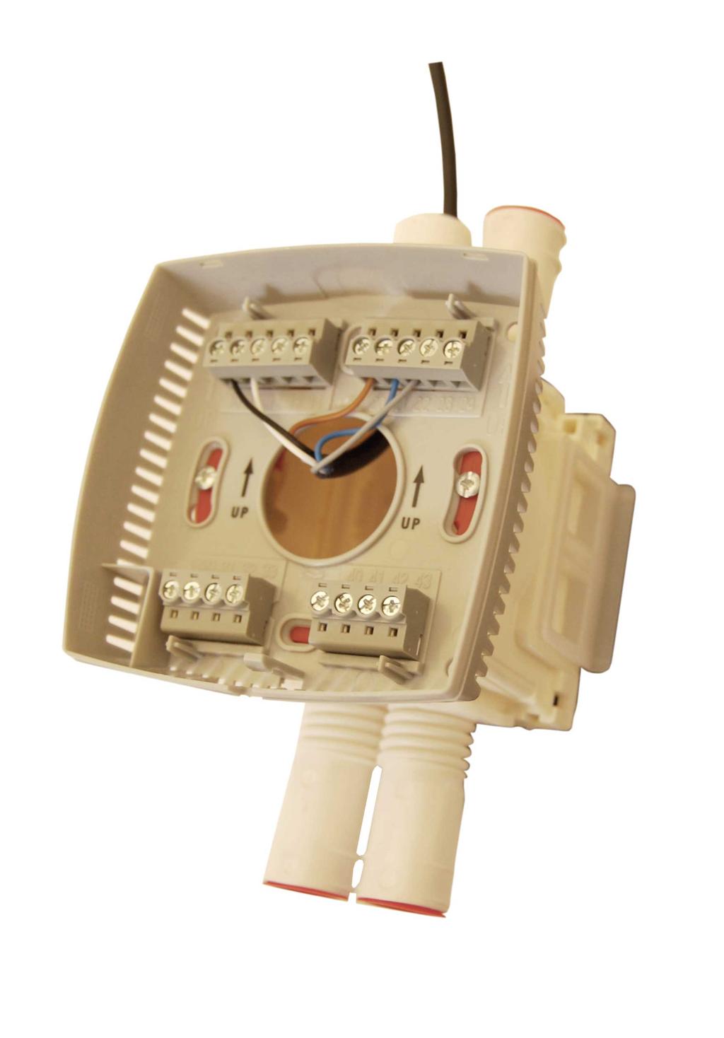
4 STRA- Installation and commissioning manual Wiring STRA- has been constructed to be as compact as possible. Therefore, the controller s communication input is not galvanically separated from the supply voltage. This means that it is important to keep G and G in order, as well as the communication input s A and B. All units that share the same transformer and communication loop must use the same transformer-pole for G (terminal ) and G (terminal ). On the communication loop the A-terminal (terminal ) should only be connected to another A-terminal and the B-terminal (terminal ) to another B-terminal. Otherwise, there is great danger of short-circuit with damaged components as a result. Terminal - Designation Operation G Supply voltage V AC G Supply voltage V No function. GDO V AC out common for DO. Internally connected to terminal, G. G V common for UO. Internally connected to terminal, G. Control output ventilation. put analog (FS). The valve actuator s V control signal terminal is connected to terminal and its supply UO terminals to terminals and. Make sure that the reference pole G is connected to the correct terminal on the actuator. Control of heating. For... V DC valve actuator, max ma. The valve actuator s V control signal terminal is connected to terminal and its supply terminals to terminals and. Make sure that the reference pole G is connected UO to the correct terminal on the actuator. alternative For V AC thermal actuator, max, A (FS). The thermal actuator is connected between terminals and, GDO. Control output cooling. For... V DC valve actuator, max ma. The valve actuator s V control signal terminal is connected to terminal and its supply terminals to terminals and. Make sure that the reference pole G is connected UO to the correct terminal on the actuator. alternative For V AC thermal actuator, max, A (FS). The thermal actuator is connected between terminals and, GDO. For external room sensor, PT. Measuring range... Sensor is connected between terminals and AI, AGnd. For -V CO sensor input. AI DI DI/CI +C AGnd A B Occupancy detector. A potential-free contact is connected between terminals and, +C. Closed contact corresponds to occupancy. See also section Occupancy detector in the chapter Operating modes. condensation detector STRZ-6 (FS). The sensor is connected between terminals and, AGnd. alternative Window contact (DI). A potential-free contact is connected between terminals and, +C. Closed contact indicates closed window. V DC out common for DI and UI (with digital function) Analogue ground, reference for AI and UI (with analogue function) RS8-communication A RS8-communication B 98 GB..6 ()
5 STRA- Installation and commissioning manual Operating modes STRA- has five different operating modes. Through the Function button you are able to switch between three of them. These are set through the parameter menu (parameter ) in the display. Occupied is the preset mode. Off Operating mode Off means that the controller is switched off, i.e. heating and cooling are disabled. However, the temperature may not drop below the set minimum temperature (parameter 6, FS 8). If it does, the controller will start heating. The background lighting on the display is not lit, and only OFF is shown in the display. Airflow will be a non-presences airflow, V, which is set on the actuator. Unoccupied (Energy Saving Mode) Operating mode Unoccupied is an energy saving mode. It means that the room where the controller is placed is not used for an extended period of time, for example during evenings, nights or weekends. The controller is prepared to change the operating mode to Occupied if someone enters the room (occupancy detector is needed to use this feature). Both heating and cooling are disabled within a temperature interval with configurable min/max temperatures (parameter respectively, FS min 9, max 7). Airflow will be a non-presences airflow, V, which is set on the actuator. However if the cooling water valve is fully open and there is still a need for more cooling, the airflow will increase to Vmin and then linearly up to Vmax if required. The background lighting on the display is not lit, but the current room temperature (or setpoint value depending on the configuration) is shown in the display. OFF is shown in the display for this operating mode as well. Standby (Energy Saving Mode) shown in the display. For more information, see Section Occupancy detector, page 6. Occupied (Normal Mode) Operating mode Occupied means that the room is in use and is therefore in a comfort mode. The controller regulates the room temperature around a heating setpoint value and a cooling setpoint value (parameter respectively, FS heating setpoint value, cooling setpoint value ). Airflow will be on a presences airflow, Vmin, which is set on the actuator. However if the cooling water valve is fully open and there is still a need for more cooling, the airflow will increase linearly from Vmin up to Vmax if required. The setpoint values can also be adjusted +/- locally via the display, or via a central command. The background lighting on the display is lit (dimmed), and the occupancy indication is shown (see Section Display, page ). The current room temperature (or setpoint value depending on the configuration) is shown in the display. Bypass (Boost Mode) Operating mode Bypass means that the controller controls the room temperature in the same way as in operating mode Occupied. For the chilled beam this activates the output for forced ventilation and the air flow goes to Vmax airflow which is set on the actuator. After a configurable time (parameter, FS 6 minutes) the controller automatically returns to the preset operating mode. Boost is normally activated when the Occupancy button is pressed or a central command. The operating mode is useful for example in conference rooms where many people are present at the same time during a limited period of time. The background lighting on the display is lit (dimmed). The occupancy indication and the symbol for forced ventilation are shown (see Section Display, page ). The current room temperature (or setpoint value depending on the configuration) is shown in the display. Activation of operating modes Operating mode Standby means that the room is in an energy saving mode and is not used at the moment. This can be during evenings, nights, weekends etc. The room temperature is controlled around the applicable heating and cooling setpoint values, with an extended temperature interval (FS +/-). Preset operating mode Airflow will be a non-presences airflow, V, which is set on the actuator. However if the cooling water valve is fully open and there is still a need for more cooling, the airflow will increase to Vmin and then linearly up to Vmax if required. Occupied is the preset operating mode. Configuration of desired operating mode is done in the parameter menu on the display (parameter ). The operating mode is changed at following events: When the Occupancy button is pressed. Activation/deactivation of an occupancy detector. Via central control, for example central time control, central booking system etc. For example, if the heating setpoint value is and the cooling setpoint value is, the controller will allow the temperature in the room to be between 9 and 7. Local adjustment of setpoint value via the display on STRA-. The background lighting on the display is lit (dimmed) and STANDBY with the current room temperature (or setpoint value depending on the configuration) are 98 GB..6 ()
6 STRA- Installation and commissioning manual Control states Function button The controllers can be configured for different control states/control sequences (Parameter, FS Heating/ Cooling with VAV-control and forced ventilation): Heating (UO) Heating/Heating (UO/UO) Heating/Cooling Heating/Cooling with VAV-control and forced supply air function (UO/UO/UO) Heating/Cooling with VAV-control (UO/UO/UO) Cooling (UO) Cooling/Cooling (UO/UO) Shutdown (Off or Unoccupied) When the Function button is held pressed down for more than seconds, the controller changes operating mode to Shutdown that can be Off or Unoccupied, regardless of the current operating mode. The activation of operating modes, Off or unoccupied can be configured via display. The factory setting is activating Unoccupied. If you press the Function button for less than seconds when the controller is in Shutdown or preset operating mode, the controller changes to Boost operating mode. If you press the button for less than seconds when the controller is in Boost, it changes operating mode to the preset operating mode. After a configurable time in Boost (FS 6 minutes), the controller returns to the preset operating mode. Occupancy detector Heating In control state Heating, the unit is always a heating controller and controls according to the heating setpoint plus/minus the setpoint displacement. The setpoint can be adjusted in the display. Heating/Heating Split output signal In control state Heating/Heating, the controller is always a heating controller and controls according to the basic heating setpoint plus the setpoint displacement. When the controller output signal reaches, it is divided between two actuators. 8 of the signal is sent to actuator and of the signal is sent to actuator. See the figure below. For local control of the operating mode regarding presence in the room, an STRZ-9- occupancy detector is connected. At occupancy control, parameter should be changed from preset operating mode to Unoccupied and parameter 7 changed to. Then the function in illustration below is attained where the controller at activated occupancy detector shifts to the Occupied operating mode. When the occupancy detector is deactivated, the controller returns to Unoccupied operating mode (to attain energy efficiency). Heating/Cooling In control state Heating/Cooling, the controller functions as a heating controller when the room temperature is lower than the basic heating setpoint plus half the neutral zone. The neutral zone is the difference in temperature between the heating setpoint and the cooling setpoint. When the room temperature exceeds this limit, the controller becomes a cooling controller. There is a hysteresis of. when the controller changes from heating to cooling controller and vice versa. When the controller is heating, it regulates according to the basic heating setpoint plus the setpoint displacement, and when it is cooling according to the basic cooling setpoint plus the setpoint adjustment. 98 GB..6 6 ()
7 STRA- Installation and commissioning manual between Vmin and Vmax. Thus cooling sequence is divided in steps, - is water cooling and - is air cooling. Sometimes you get free cooling by air, if outside temperature is cooler than the setpoint room temperature. Then the STRA- can shift the sequence so that - is air cooling and - is water cooling. This is adjusted by changing the parameter Free cooling off Water cooling - and - air cooling 9 - Free cooling on Air cooling - and - water cooling Free cooling can also be turned on and off through Modbus communication. Cooling In control state Cooling, the unit is always a cooling controller and controls according to the basic cooling setpoint plus the setpoint displacement. Cooling/Cooling Split output signal In control mode Cooling/Cooling, the controller always functions as a cooling controller and controls according to the basic cooling setpoint plus the setpoint displacement. When the controller output signal reaches, it is divided between two actuators. 8 of the signal is sent to actuator and of the signal is sent to actuator. See the figure below. Figure : Cooling sequence without free cooling CO control STRZ-8-- is an active CO detector (-V). This accessory provides the functionality that the controller changes the airflow linearly between Vmin and Vmax. The nozzle setting is increased when the PPM level is in excess of the parameter value ( ppm) and reaches the maximum nozzle setting (parameter ) when the ppm level is in excess of paramater ( ppm). Heating/cooling control (PI) is preformed simultaneously with the CO control and if a cooling or heating need occurs the signal is directed to respectively output (UO and UO). Parameter 8 should be set to in order to activate the CO function. Free cooling Figure : Cooling sequence with free cooling Actuators STRA- can be used with two types of actuators: Analogue V actuators Thermal actuators The actuator type is set via the parameter menu in the display (parameter and ). Note that an adapter might be needed if another actuator than STRZ-7 is used. In normal operation, the cooling sequence prioritize to use water cooling, i.e. output UO where the water cooling valve is connected. If the water cooling is not enough to reach the setpoint, the airflow is increased linearly 98 GB..6 7 ()
8 STRA- Installation and commissioning manual Analogue actuators The following output signals can be set for analogue actuators: V (FS) V V V Thermal actuators When thermal actuator control has been selected, this is controlled digitally with time proportional pulses via universal outputs (UO). By pulsing, the opening degree of the actuator (and its valve) is varied. The period (time in seconds) is the sum of the on and off. The period time is FS6s. The controller varies the on and off output times proportionally depending on the output signal demand to the actuator. Actuator exercise All actuators are exercised. The exercise takes place at set intervals in hours (FS hours interval). An opening signal is sent to the actuator for as long time as the run time has been configured. Then a closing signal is sent for as long time and the exercise is finished. Condensation detector There is a special input (CI) on STRA- controllers. This input is intended for condensation detector, STRZ-6, and functions internally as a digital input, i.e. condensation or no condensation. When the condensation detector is activated, the cooling control is blocked and the controller is set in neutral position. When condensation ceases, the controller will start controlling from the neutral position. Window Contact When the window contact has been configured, the regulator is set to normal operation when window is closed. If the window is open, the regulator is set in off mode, heating and cooling outputs are set to V and the frost protection function is activated. Frost protection STRA- has built-in frost protection, which is activated when the controller is not in use. The frost protection prevents the temperature from dropping below 8. Return to normal fan speed and control occurs automatically when the room temperature exceeds 8. Control the light with an occupancy sensor It is possible to control the operation of the light with an occupancy sensor through a relay and its socket (STRZ-7-b). The light will switch off when the room is unoccupied. The socket for wiring is screwless quick connection. Parameter 6 should be changed to when using this function. Wiring diagram: 98 GB..6 8 ()
9 STRA- Installation and commissioning manual Parameter Settings STRA- is delivered with a number of factory settings. To acquire the desired function, the controller must be adapted to its specific application. This is done through the parameter menu in the display. Applications may vary and incorrectly set parameters can effect the controller and application negatively. Be sure to set the necessary parameters relevant for your application. If you experience problems, contact TSS controls. Parameter menu It is possible to set different parameter values in a parameter menu. The parameter menu is accessed by simultaneously holding the INCREASE and DECREASE buttons pressed for about seconds and then pressing the INCREASE button twice. The Service indication will be displayed. First the display will show the parameter number. Scroll between parameters by using the INCREASE and DECREASE buttons. Press the Function button to select the desired parameter. The parameter number will be replaced by the parameter value. The value can be changed using the INCREASE and DECREASE buttons. If a button is held pressed, the value will start scrolling, first slowly and then with increasing speed in steps with seconds between steps. Acknowledge/Regret To acknowledge and store a set parameter value, press the Function button again, the display then returns to showing the parameter number. To retrieve the original value, i.e. the value before change, press the INCREASE and DECREASE buttons at the same time. The original value is shown on the display. Return After a certain time, about minute, or when the INCREASE and DECREASE buttons are pressed at the same time while in the menu, the display returns to the normal view. Exit is shown on the display after the last parameter (or before first parameter). The parameter menu is exited by pressing the Function button on the Exit choice in parameter menu. Parameter list Table : The following parameters can be changed in the parameter menu (FS Factory setting): Parameter number Description Occupied Heating Setpoint Occupied Cooling Setpoint Standby Neutral Zone Unoccupied Heating Setpoint Unoccupied Cooling Setpoint Frost protection Setpoint P-Band I-Time Cooling Changeover difference temperature (Room and media) Heating Changeover difference temperature (Room and media) Heating/Cooling Functions Boost Mode Timer P.I.R Delay Off P.I.R Delay On Connected sensor on AI 6 UI Signal Values 98 GB..6 Unit FS STRA- Seconds Heat, Heat/Heat, Heat or Cool via changeover, Heat/Cool, Heat/Cool with VAV and forced ventilation, Heat/Cool with VAV, 6 Cool, 7 Cool/Cool, 8 Heat/Cool with UO, 9 Heat/Cool with Change-Over 8 Minutes Minutes Minutes 9 () internal, external, Change over sensor Disabled, Change over sensor digital, Change over sensor analogue 6
10 STRA- Installation and commissioning manual Parameter number Description 7 Connected sensor DI 8 Connected sensor DI Function of UO Signal Function of UO Signal Function of UO Signal UO output in manual mode Values Actuator type for UO 9 Heating Modulating Actuator Control Cooling Modulating Actuator Control Heating Thermal Actuator Time Cooling Thermal Actuator Time Travelling Time for Increase/Decrease Heating Valve (Not in use) Travelling Time for Increase/Decrease Cooling Valve (Not in use) Increase/Decrease NZ (Not in use) Heating Valve Periodic Exercise Interval Cooling Valve Periodic Exercise Interval Hysteresis for the heating thermostat function Hysteresis for the cooling thermostat function The minimum heat output in heating mode Fan runs on low speed (Not in use) Display View Highest Setpoint Offset Increase Lowest Setpoint Offset Decrease Normal Mode Function 6 Energy Saving Mode Function 98 GB..6 Disabled, Window contact, P.I.R, Change over sensor Disabled, Window Contact, Condensation Sensor, Change over sensor Thermal actuator heating, Heating actuator...v, On/off actuator heating, None Thermal actuator Cooling, Cooling actuator V, On/off actuator cooling Forced Vent Digital, Forced Vent Step Analog, Ordinary Analog output, Control of EC-fan -v, -v, -v, -v -v, -v, -v, -v -v, -v, -v, -v Seconds Seconds 6 6 Seconds Seconds Hours Hours K K Actual Temp Value, Heating Setpoint, Cooling Setpoint, Average of Heating/Cooling, Only Setpoint Displacement, CO, 6 Heating Setpoint + Setpoint Displacement, 7 Cooling Setpoint + Setpoint Displacement, 8 Average of Heating/Cooling Setpoints + Setpoint Displacement, 9 Calculated flow in l/s Off, Unoccupied, Standby, Occupied Off, Unoccupied () Inactive Inactive FS STRA Unit
11 STRA- Installation and commissioning manual Parameter number Description BMS Operating Mode Unit Off, Unoccupied, Standby, Occupied, Not Used, No Remote control Fan Control (Not in use) Fan Speed Limit (Not in use) Fan Speed Limit (Not in use) Fan Speed Limit (Not in use) Fan Start/Stop Hyst (Not in use) Fan Speeds External Temperature Sensor Calibration Gain AI Sensor Calibration Gain UI Internal Temperature Sensor Calibration Gain Filter factor for AI temperature 6 Normally open/normally closed DI 6 Normally open/normally closed DI 6 Normally open/normally closed UI 6 Heating Manual Override 6 Cooling Manual Override 6 Forced ventilation Manual Override 66 Changeover Manual Override Manual Mode Heating Output Manual Mode Cooling Output 69 Modbus Address 7 Modbus Parity 7 7 Modbus Timeout Modbus Response Delay 7 Heating output 7 HMI Displacement View 7 Free Cooling 76 Forced Ventilation control mode 77 P.I.R Activated Operation Mode The Controller PLA Address. Used in EXOline The Controller ELA Address. Used in EXOline 8 Cool output 98 GB..6 FS STRA- Minimum airflow on cooling UO in of -V. Parameter is in use when cooling/heating mode with VAV is selected Maximum airflow on cooling UO in of -V. Parameter is in use when heating/cooling mode with VAV is selected Values No Control, Heating, Cooling, Both N/O, N/C N/O, N/C N/O, N/C Off, Manual, Auto Off, Manual, Auto Off, Manual, Auto Heating, Cooling, Auto, Odd, Even Set by production (same as EXOline ELA) Milliseconds Milliseconds For N/C-actuator, For N/O-actuator The offset, The active setpoint + offset, The heating setpoint + offset, The cooling setpoint + offset, Occupied Heating Setpoint + Offset, Occupied Cooling setpoint + Offset, 6 Occupied Average + Offset Not Available, Available No Action, Forced on Heat/Cool output at, Forced on Cool output at Occupied, Bypass Set by Production Set by Production For N/C-actuator, For N/O-actuator ()
12 STRA- Installation and commissioning manual Parameter number Description 8 AI Input 8 8 Flow at volt on AI (Not in use) Flow at volt at AI (Not in use) The minimum time the valve is open when the calculation of change over is made Alarm triggers when temperature falls below Alarm triggers when temperature raise above CO Level to Change to Boost Mode Values Unit Disable, CO, -, Flow calculation, -V FS STRA- l/s l/s Seconds 6 PPM PPM 6 CO Level below "Boost Mode CO Start" value to start Boost Mode Timer countdown AI CO Filter CO Sensor PPM for v PPM CO Sensor PPM for v PPM VAV CO Minimum Limit PPM VAV CO Maximum Limit PPM Port Mode EXOline/Modbus, BACnet BACnet address Above 7 Slave 6 BACnet device ID low figures 7 BACnet device ID high figures 8 BACnet Max Master 98 9 Com Speed Reset com to factory default (Modbus 9K6, 8, N, ) The lowest output the fan will need to start (Not in use) The highest speed of the fan (Not in use) The Model in Regin Range Major Version Minor Version Branch Version Revision Voltage x for nozzle Voltage x for nozzle Voltage x for nozzle Voltage x for nozzle Max air level at cooling Max air level at CO 9 Free Cooling Type of STRA 6 7 The floor the STRA is placed at The room the STRA is placed High digits of the serial number Mid digits of the serial number Low digits of the serial number Legacy Mode, set to to use the old wiring terminal order 8, Set by Production (Last Digits of ELA) Set by Production ("A" of PLA & ELA) Set in Production, uses "PL" of PLA 7 Com bus speed: 96, 9, 8, 768 (BACnet) V V 99 STRA-7, 9 STRA- / STRA-, 9 STRA- Read Only Air level at Off, Unoccupied & Standby Air level at Occupied mode Air level Boost mode (Button only) Not Available, Available STRA- / STRA-*, STRA Not Used in IPSUM 9999 Not Used in IPSUM Air on Pin, Boost on Pin, Air on Pin, Boost on Pin Note: * additional parameter setting required; P8, P, P, P8, P8, P76, P8 98 GB..6 ()
ROOM CONTROLLER STRA-24 TECHNICAL CATALOUGE AND INSTALLATION
 ROOM CONTROLLER STRA-24 TECHNICAL CATALOUGE AND INSTALLATION 2 STRA-24 Room Controller for chilled beams - Technical catalouge and installation STRA-24 ROOM CONTROLLER FOR CHILLED BEAMS DESCRIPTION STRA-24
ROOM CONTROLLER STRA-04 TECHNICAL CATALOGUE AND INSTALLATION
 ROOM CONTROLLER STRA-04 TECHNICAL CATALOGUE AND INSTALLATION 2 STRA-04 Room Controller - Technical catalogue and installation STRA-04 ROOM CONTROLLER FOR OPTIVENT DESCRIPTION STRA-04 is a preprogrammed
RC-DO. Room controllers with display and manual forced ventilation function
 revision 10 2017 RC-DO Room controllers with display and manual forced ventilation function RC-DO is a room controller from the Regio Mini series intended to control heating and cooling in a single zone.
Modbus Integration Integration for Modbus Functionality for VT8600 Series
 Modbus Integration Integration for Modbus Functionality for VT8600 Series Building Management System *For data visualization and analysis Modbus Controller VT8000 Series room controllers 2 TABLE OF CONTENTS
Commissioning manual. - Simplified VAV solution with full potential... Rev. Pascal-Comm RM-ver / RC-ver 1.
 Commissioning manual - Simplified VAV solution with full potential... Rev. -Comm. 22-09-2014-9 RM-ver 1.0-1-08 / RC-ver 1.3-1-10 Table of content Table of content Page Overview system and description 4
HERZ Electronic room thermostat analog and digital
 Dimension in mm 3 F799 11-3 F799 14 HERZ Electronic room thermostat analog and digital Data sheet for F799, Issue 0317 3 F799 15 3 F799 18 Mounting plate Page 1 Technical data 3 F799 11-14 3 F799 15-18
ADAPTTM. Extract. Extract air diffuser for the WISE system. Quick Selection
 ADAPTTM Extract Extract air diffuser for the WISE system Quick facts Active damper Pressure-dependent and cleanable Integrated sensor module Simple wiring, Plug & Play Communication via Modbus RTU Supplied
ADAPTTM. Sphere. Active communicative, supply air diffuser for the WISE system. Quick Selection
 ADAPTTM Sphere Active communicative, supply air diffuser for the WISE system Quick facts Supply air diffuser with an active damper Pressure-dependent and cleanable Integrated sensor module Simple wiring,
Energy Control/Motorized Energy Control
 The patented Energy Control function allows the air flow to be adjusted easily to provide a comfortable indoor climate. This function also permits a choice of air flow patterns (two-way, one-way and intermediate
ADAPTTM. Free. Active communicative, supply air diffuser for the WISE system, ADAPT F
 ADAPTTM Free Active communicative, supply air diffuser for the WISE system, ADAPT F Quick facts Supply air diffuser with an active damper Pressure-dependent and cleanable Integrated sensor module Simple
Observe all necessary safety precautions when controlling the soft starter remotely. Alert personnel that machinery may start without warning.
 Introduction OPERATING INSTRUCTIONS: MCD REMOTE OPERATOR Order Codes: 175G94 (for MCD 2) 175G361 + 175G9 (for MCD 5) 175G361 (for MCD 3) 1. Introduction 1.1. Important User Information Observe all necessary
Ventilation in balance
 Ventilation in balance AIRLINQ - DIGITAL BMS PARAMETERS FOR MODBUS RTU RS485 BASIC INFORMATION The present document is only valid for air handling units with firmware version 6. or newer. The firmware
Control Solutions Biofloor
 MCF234 Distributor for Wired Control System COMAP proposes a new control system for heating and cooling underfloor. Consisting of a 6 or 10- channels controller (MCF234), analogic (TAF234) or electronic
ST48-WHUV.102. Wiring diagram. Product description. PID controller. Order number
 ST48-WHUV.12 PID controller Order number 935.15 Wiring diagram Product description This micro-processed controller serves for temperature control at high measuring accuracy. Beside resistance sensors and
Ventilation in balance
 Ventilation in balance AIRLINQ - DIGITAL BMS PARAMETERS FOR BACNET TM /IP. BACNET TM MS/TP BASIC INFORMATION The present document is only valid for air handling units with firmware version 6. or newer.
SMT-150 Installer Manual
 SMT-150 Installer Manual 3 Stage Digital HVAC Controller Version 1.0 Version History January 2019 Version 1 - Original Document Thank you for your purchase of this premier product. Please take the time
IQ STAR NOVA II CHILLED BEAM» TECHNICAL DATA
 AIR COMFORT AIR DIFFUSION CHILLED BEAMS IQ STAR NOVA II CHILLED BEAM» TECHNICAL DATA 2 Chilled beam IQ Star NOVA II Technical data CHILLED BEAM IQ STAR NOVA II The NOVA II chilled beam is an active chilled
RDG160TU Commercial Thermostat
 Document No. 129-588 RDG160TU Commercial Thermostat Selecting Location Install the thermostat about 4 feet (120 cm) above the floor on an inside wall. Ensure that there is free airflow around the thermostat.
CHILLED BEAM IQ STAR WEGA II
 CHILLED BEAM IQ STAR WEGA II TECHNICAL CATALOGUE 2 IQ Star WEGA II Chilled beam - Technical catalogue CHILLED BEAM IQ STAR WEGA II The WEGA II chilled beam is an active chilled beam system for ventilation,
SE8300 Series Installation Guide 24 Vac Low Voltage
 Installation Guide 24 Vac Voltage mercial and Hotel/Lodging HVAC Fan Coil Applications CONTENTS Installation 2 Configurable BI/UI Universal Inputs Overview 3 Setup Screen Display 3 Terminal Identification
Room product for Swegon s WISE System for demand-controlled ventilation
 Room product for Swegon s WISE System for demand-controlled ventilation QUICK FACTS Integrated temperature sensor Modbus RTU-communication Simple wiring: Plug and Play Available as a package solution for
AIR VOLUME TRANSMITTER / CONTROLLER IML
 1131.60en 03.04.2013 AIR VOLUME TRANSMITTER / CONTROLLER IML IML air volume transmitter is designed for detecting and controlling air volumes in air handling units and room spaces. Air volumes are calculated
HFB - Airflow Management Damper HFB. Airflow Management Damper. Product models and Accessories
 HFB Airflow Management Damper Control damper for different airflow and duct pressure control applications Pressure-independent operation Galvanised steel design Circular duct connection equipped with integrated
ELECTRIC POWER REGULATION TEMPERATURE CONTROLLERS. room C
 ELECTRIC POWER REGULATION STS converts 0 10 V signal to one time proportional and up to 3 contact. Each step must be identical in power. input output 1 2- number of steps 2 Vac, 1 VA 0 10 Vdc < 1 ma for
RVP-R VAV REGULATORS. Intended use: VAV regulators are used for automatic airflow regulation in the ventilation and air conditioning systems.
 RVP-R VAV REGUATORS Intended use: VAV regulators are used for automatic airflow regulation in the ventilation and air conditioning systems. Intended use VAV regulators are used for automatic airflow regulation
Installation Guide. ECL Comfort 210 / 310, application A231 / A Table of Contents
 1.0 Table of Contents 1.0 Table of Contents... 1 1.1 Important safety and product information..................... 2 2.0 Installation... 4 2.1 Before you start.....................................................
Appendix A: Inputs, Outputs, and Parameters
 Technical Bulletin Issue Date 11/01/01 TECHNICAL BULLETIN Appendix A: Inputs, Outputs, and Parameters Introduction This appendix describes the inputs, outputs, and parameters used with the Metasys Zoning
MATRIX LLC LEVEL CONTROL PANEL
 MATRIX LLC LEVEL CONTROL PANEL Installation Operation Maintenance Manual 1-26-09 REV-0.3 1 INDEX Introduction. 3 Product Configurations..... 4 I/O Descriptions. 8 Operation o Intercooler, Accumulator,
PCT-3001 plus. Display LCD
 PCT3 plus DIGITAL PRESSURE CONTROLLER FOR COOLING PLANTS DESCRIPTION Pressure controller for refrigeration systems capable to control suction (compressors) and discharge (fans) pressures. It is possible
Temperature Controller (Heat Pumps)
") 3 345 Temperature Controller (Heat Pumps) For comfort control in HVAC systems RWD31 RWD41 Stand-alone electronic temperature controller Four 2-position (On/Off) outputs Easy adjustment of parameters via
3 345 Temperature Controller (Heat Pumps) For comfort control in HVAC systems RWD31 RWD41 Stand-alone electronic temperature controller Four 2-position (On/Off) outputs Easy adjustment of parameters via
V200 V200. Control on water, proportional integral. Simplified Master / Slave operation GENERAL DESCRIPTION
 Master Slave 1 Slave (n + 1) Master Slave 1 Slave (n + 1) Simplified Master / Slave operation GENERAL is a CIAT electronic control system designed to control non-independent air conditioning terminal units
ELIOS 25 DIGITAL CONTROL UNIT WITH LCD DISPLAY FOR THERMAL SOLAR SYSTEMS TDS 006 M00 0SE A
 ELIOS 25 DIGITAL CONTROL UNIT WITH LCD DISPLAY FOR THERMAL SOLAR SYSTEMS TDS 006 M00 0SE 012945A0 040906 1 MAIN FEATURES Power supply 230V~ ±10% 50Hz Backlit alphanumeric LCD display Management of 5 output
SE7200 Series Installation Guide
 SE7200 Series Installation Guide 24 VAC Low Voltage Zoning Terminal Equipment Controller For Commercial HVAC Applications CONTENTS Installation 2 Preparation 2 Location 2 Installation 2 Configurable BI/UI
Metasys Zoning Package Installation
 Technical Bulletin Issue Date August 28, 2002 Metasys Zoning Package Installation Metasys Zoning Package Installation...2 Introduction... 2 Key Concepts... 3 Installation Overview... 3 Metasys Zoning Package
MANUAL INSTALLATION. Tracking Controller. TC Series. v100 Issue Date: 02/25/ Price Industries Limited. All rights reserved. Firmware: 1.3.
 MANUAL INSTALLATION Tracking Controller TC Series v100 Issue Date: 02/25/16 2016 Price Industries Limited. All rights reserved. Firmware: 1.3.0 TABLE OF CONTENTS Product Overview General...1 Tracking Controller
HBLT-C1 Controller. Instruction Manual. For pump control of levels in industrial refrigeration systems
 Instruction Manual HBLT-C1 Controller For pump control of levels in industrial refrigeration systems Instruction manual HBLT-C1 Controller (006-UK) 1 / 14 Table of Contents Safety Instructions... 3 Introduction...
Accessories STRA Room Controller
 Accessories STRA Room Controller External temperature sensor, STRZ-5-b Technical data room sensor: STRZ-5-5 C PT, DIN class B IP Technical data external sensor: STRZ-5-2 - +7 C PT, DIN class B Technical
ST Wiring diagram. Product description. Temperature controller. Order number
 ST7-31.3 Temperature controller Order number 9154.12 Wiring diagram Product description The switching exits of the thermostatic controller can be programmed as -two-point controller with alarm -three-point
SED2. Variable Frequency Drives. with Conventional Bypass Options. Variable Frequency Drives. Description. Features F-9.
 SED2 with Conventional Bypass Options Important Note: VD products are only available through authorized distribution channels. To locate an authorized distributor, please contact a Siemens Building Technologies
QUOTATION BLADE 7 LX. Product code GEAL6S2BAA
 1 of 10 Mattei rotary vane compressors are the result of 90 years of investments in research and development to improve performance and lessen the impact on the environment. Designed for industrial continuous
OPERATING INSTRUCTIONS ECON-M
 OPERATING INSTRUCTIONS ECON-M INDEX 1.0 Introduction 2.0 Salient features, Protection & Supervision 3.0 Display/ Front Panel 4.0 Switches Description 5.0 LED Annunciations Description 6.0 Lamp Test 7.0
lindab comfort Regula Control er
 lindab comfort Regula Controller Regula Controller Control equipment for waterborne cooling and heating systems. Use Regula Mono, Duo and Regula Lon control the cooling and heating of a room in sequence
MiG2 TIME SWITCHES. 1, 2 & 4 Channel, 365 Day, Energy Saving Time Switches
 MiG2 TIME SWITCHES 1, 2 & 4 Channel, 365 Day, Energy Saving Time Switches The MiG2 series of timers are programmable 365-day time-switches, incorporating: Multiple switching times per day Single and block
HGM501 Gen-set Controller USER MANUAL. Smartgen Technology
 HGM501 Gen-set Controller USER MANUAL Smartgen Technology Contents 1. 2. 3. 4. 5. 6. 7. 8. 9. OVERVIEW... 4 PERFORMANCE AND CHARACTERISTICS... 4 TECHNICAL DATA... 5 OPERATION... 6 4.1. BUTTON DESCRIPTION...
US-S/FFL. Ultrasonic energy meters. Function. Flexible design. Connection. Mounting. High reliability
 Revision 2017-08-15 Ultrasonic energy meters Flanged ultrasonic energy meters, intended for heating or cooling. Size DN25 DN100 Nominal flow 3.5 60 m³/h For horizontal or vertical mounting No data loss
FKP-R/R2. User Guide for Pressure and Temperature controller with integrated pressure sensor
 FKP-R/R2 User Guide for Pressure and Temperature controller with integrated pressure sensor Rev 1.6 Frabil El AB Phone: +46 40-287090 Bjurögatan 38 Fax: +46 40-184709 2 FKP-R2 FUNCTION FKP-R/R2 is a complete
Installation, Service, and Troubleshooting Instructions
 Installation, Service, and Troubleshooting Instructions Page GENERAL........................................ 2 INSTALLATION................................. 2-4 Zone Controller Placement.......................
SPEEDRIVE INSTRUCTIONS MANUAL
 EN SPEEDRIVE INSTRUCTIONS MANUAL Safety warning. The following symbols shown beside a paragraph represent danger warnings associated to the failure to comply with the corresponding instructions. DANGER!
Digital Fan Coil Thermostats with 0(2)-10 VDC Fan Output
-10 VDC Fan Output") TCAF Series Digital Fan Coil Thermostats with 0(2)-10 VDC Fan Output Issue Date March 1, 2018 Features Ultra slim wall-mount unit to match any décor Large easy-to-read Liquid Crystal Display (LCD), with
TCAF Series Digital Fan Coil Thermostats with 0(2)-10 VDC Fan Output Issue Date March 1, 2018 Features Ultra slim wall-mount unit to match any décor Large easy-to-read Liquid Crystal Display (LCD), with
APPLICATION GUIDE. Simplicity LINC GATEWAY OVERVIEW. 24 must be grounded close to the Simplicity LINC
 APPLICATION GUIDE Simplicity LINC GATEWAY OVERVIEW The Simplicity LINC Gateway operates as a Modbus Client providing an interface between a MS/TP control system and devices that communicate using the Modbus
ecotrans Lf 01/02 Microprocessor Transmitter / Switching Device for Conductivity
 Data Sheet 20.27 Page / ecotrans Lf 0/02 Microprocessor Transmitter / Switching Device for Conductivity Type 2027 Housing for DIN rail mounting (5 x 7.5 mm to EN 0 75 A.) Brief description The JUMO ecotrans
ELECTRONIC THERMOSTAT: T901
 μnistδt ELECTONIC THEMOSTAT: T One contact output DESCIPTION The T series proportional thermostats are microcomputer based, proportional and integral (PI) devices with one contact time proportioning output.
APP EOLE4. Applicable to program versions TAC5 Version DT & DG 2.7.0
 APP EOLE4 Applicable to program versions TAC5 Version DT 2.8.2 & DG 2.7.0 2 THE APP EOLE4 INTERFACE This interface can be used on Android, IOS and PC. Download the app from the App Store/Google Play or
4 x 0-10Vdc Channels Fused 24V o/p terminals for actuator power Direct or buffered output signals
 IO Input/Output Modules IO-ABM4 Analogue Override Module Description IO-ABM4 Analogue Override Module Intended for applications which require independent manual override of analogue output channels from
PCT-3000 plus DIGITAL PRESSURE CONTROLLER FOR COOLING PLANTS
 PCT plus DIGITAL PRESSURE CONTROLLER FOR COOLING PLANTS Ver. DESCRIPTION The PCT plus is a pressure controller for refrigeration plants that require control in their suction and discharge stages. With
Digital Room Thermostats with Touch Screen LCD
 TC40 Touch Series Digital Room Thermostats with Touch Screen LCD Revision Date February 22, 2013 Features Wall-mount Display Control to match any decor Extra large easy-to-read Liquid Crystal Display (LCD),
Cooling mode. Temperature adjustment button. Override button. 24 VAC COM AN1 COM OPEN CLOSED T2/AN2 T2/COM T3 T3 COM SENSOR COM C-Over COM NSB
 TB6980/TB7980 1. Introduction The TB6980/TB7980 digital thermostats provide proportional plus integral individual space temperature control in zoned commercial HVAC systems such as hydronic and pressure
Variable Air Volume Dampers
 OVAV 2000 SERIES OPTIMA VAV DAMPERS Overview OPTIMA make Variable Air Volume (OVAV) box is a part of an Air Conditioning system. It is located inside the duct work. VAV Dampers are designed to control
TTT802 Gearshift Controller, Part # R1N-S (Standard), -P (Paddleshift)
, -P (Paddleshift)") First, Sign and Date Bln 2009-03-9 Updated, Sign and Date Bln 200-04-29 (0) User Manual TTT802 Gearshift Controller Firmware for R--N-2- TTT802 Gearshift Controller, Part # 2-620-9-RN-S (Standard), -P
First, Sign and Date Bln 2009-03-9 Updated, Sign and Date Bln 200-04-29 (0) User Manual TTT802 Gearshift Controller Firmware for R--N-2- TTT802 Gearshift Controller, Part # 2-620-9-RN-S (Standard), -P
ECONOMISER SERIES E2T USER MANUAL
 TURBO S.R.L. Electronic Control Systems for Dust Collectors e-mail: info@turbocontrols.it web: www.turbocontrols.it TEL. ++39 (0)362 574024 FAX ++39 (0)362 574092 ECONOMISER SERIES E2T USER MANUAL 24/06/2014
ECL Apex 10. User Guide. ECL Apex 10 *087R9745* Installation and configuration. *vijem102*
 User Guide ECL Apex 10 *087R9745* *vijem102* Installation and configuration VI.JE.M1.02 Danfoss 11/2004 DH-SMT VI.JE.M1.02 Danfoss 11/2004 DH-SMT ECL Apex 10 VI.JE.M1.02 Danfoss 11/2004 DH-SMT VI.JE.M1.02
RWBa. ROOM CONTROL EQUIPMENT Electronic control of cooling and heating. RWBa
 ROOM CONTROL EQUIPMENT Electronic control of cooling and heating. ROOM CONTROL EQUIPMENT RWBa For sequential control of heating and cooling, or cooling/ heating only. Electromechanical actuators provide
ExBin-P Pressure switches 5 Pa Pa
 ExBin-P Pressure switches 5 Pa... 5.000 Pa Electrical, explosion-proof binary pressure / differential pressure switches 5 Pa...100 Pa with adjustable switch activation delay 24 VAC/DC supply voltage, potential
HGM7100N SERIES (HGM7110N/7120N) GENSET CONTROLLER USER MANUAL
 GENSET CONTROLLER USER MANUAL") HGM7100N SERIES (HGM7110N/7120N) GENSET CONTROLLER USER MANUAL SMARTGEN (ZHENGZHOU) TECHNOLOGY CO., LTD. Chinese trademark English trademark SmartGen make your generator smart SmartGen Technology Co.,
HGM7100N SERIES (HGM7110N/7120N) GENSET CONTROLLER USER MANUAL SMARTGEN (ZHENGZHOU) TECHNOLOGY CO., LTD. Chinese trademark English trademark SmartGen make your generator smart SmartGen Technology Co.,
HFB - Airflow Management Damper. Halton HFB. Airflow Management Damper
 Halton HFB Airflow Management Damper Control damper for different airflow and duct pressure control applications Pressure-independent operation Galvanised steel design Circular duct connection equipped
Supersedes CL2 (512) Form CL2 (615) STARTUP CHECKLIST PHONE: CUSTOMER ORDER NO: JCI TEL NO: JCI ORDER NO: JCI CONTRACT NO:
 Form CL2 (615) STARTUP CHECKLIST PHONE: CUSTOMER ORDER NO: JCI TEL NO: JCI ORDER NO: JCI CONTRACT NO:") YMC 2 - MOD A STARTUP CHECKLIST Supersedes 160.78-CL2 (512) Form 160.78-CL2 (615) STARTUP CHECKLIST CUSTOMER: JOB NAME: ADDRESS: LOCATION: PHONE: CUSTOMER ORDER NO: JCI TEL NO: JCI ORDER NO: JCI CONTRACT
YMC 2 - MOD A STARTUP CHECKLIST Supersedes 160.78-CL2 (512) Form 160.78-CL2 (615) STARTUP CHECKLIST CUSTOMER: JOB NAME: ADDRESS: LOCATION: PHONE: CUSTOMER ORDER NO: JCI TEL NO: JCI ORDER NO: JCI CONTRACT
ALC-PRM-VFC. Ceiling Mounted Photocell. Product Guide. Overview. Features
 Product Guide ALC-PRM-VFC Ceiling Mounted Photocell Overview The ALC-PRM-VFC photocell will turn lighting on when the ambient light falls below a preset level. The lighting will then be turned off when
USERS MANUAL MCD REMOTE OPERATOR
 USERS MANUAL MCD REMOTE OPERATOR Order Code: 175G9004, 175G3061 Contents Contents Introduction...2 Important User Information...2 General Description...2 Symbols Used in this Manual...2 Installation...3
Temperature Controller OVATION 214 User's Guide
 Temperature Controller User's Guide Read this guide carefully before using the controller. 890-00045 rev.00 TABLE OF CONTENTS Page TABLE OF CONTENTS... 2 PRECAUTIONS... 3 FEATURES... 4 LOCATION OF THE
SAX Electronic Valve Actuator
 SAX Electronic Valve Actuator Non-spring Return, 24 Vac, Proportional Control Technical Instructions Document No. 155-506 Description The SAX Non-spring Return (NSR), Electronic Valve Actuator requires
Superstatic 440. Static Heat- and Cooling Meter. Application
 Superstatic 440 Static Heat- and Cooling Meter Application Design The Superstatic 440 is a static heat- and cooling meter according to standard EN1434 class 2 based on the fluid oscillation principle,
HWS Heater (alternative) Electric Heater Stage 2 IQLVAV Electric Heater Stage 1. , P Serial Fan on/off SUPPLY AIR. Parallel Fan
 Electric Heater Stage 2 IQLVAV Electric Heater Stage 1. , P Serial Fan on/off SUPPLY AIR. Parallel Fan") Data Sheet Variable Air Volume Strategy HWS Heater (alternative) Electric Heater Stage 2 IQLVAV Electric Heater Stage 1, P Serial Fan on/off Variable Fan damper Lon 2, 3, 4-port modulating valve Variable
Data Sheet Variable Air Volume Strategy HWS Heater (alternative) Electric Heater Stage 2 IQLVAV Electric Heater Stage 1, P Serial Fan on/off Variable Fan damper Lon 2, 3, 4-port modulating valve Variable
EXPERT 2V4SA. Temperature Controller. User s manual CLEAN MODE COMPENSATION HUMIDITY OUTSIDE TEMPERATURE
 CLEAN MODE Temperature Controller User s manual CURRENT CONDITIONS ROOM TEMPERATURE PROBE TEMPERATURE OUTSIDE TEMPERATURE RELATIVE HUMIDITY STATIC PRESSURE TIME / DATE SETTINGS SET POINT / CURVE MINIMUM
BACnet PTEC Controller VAV Chilled Beam with Demand Control Ventilation (CO2) and Floating or Analog Output Owner s Manual
 and Floating or Analog Output Owner s Manual") BACnet PTEC Controller VAV Chilled Beam with Demand Control Ventilation (CO2) and Floating or Analog Output Owner s Manual 125-5104 Building Technologies Table of Contents How To Use This Manual... 4
BACnet PTEC Controller VAV Chilled Beam with Demand Control Ventilation (CO2) and Floating or Analog Output Owner s Manual 125-5104 Building Technologies Table of Contents How To Use This Manual... 4
Delta Products VFD CP2000 Bypass Control Packages.
 Delta Products VFD CP2000 Bypass Control Packages www.deltaww.com Delta Products VFD CP2000 Bypass Control Packages The Delta Products VFD CP2000 Bypass Control Packages are designed for the Delta Products
CCO kit. Compact Change Over - 6-way switch valve with motor QUICK FACTS
 kit Compact Change Over - 6-way switch valve with motor QUICK FACTS Enables heating & cooling in products with only one heat exchanger circuit Precise flow regulation For 4-pipe cooling/heating system
Company name: GSI Created by: Xiao Ying Wong Phone: Date: 10/03/2017 Client: Client Number: Contact:
 Position Qty. Description 2 NBG 125-8-16/156 A-F2-A-BAQE Product No.: On request Non-self-priming, single-stage, centrifugal volute pump designed according to ISO 5199 with dimensions and rated performance
MB A 12V/24V DC PROGRAMMABLE DUAL BATTERY ISOLATOR
 MB-3688 120A 12V/24V DC PROGRAMMABLE DUAL BATTERY ISOLATOR User Manual Warning and Precautions MB-3688 is built with corrosion resistant material and the main electronic assembly is well sealed inside
DTR CG OPTIMA ver.3.0 ( )
") Compact controlling units of supply as well as supply and exhaust air-handling units VS 10 75 CG OPTIMA VS 40 150 CG OPTIMA SUP VS 40 150 CG OPTIMA SUP EXH Operating and maintenance manual DTR CG OPTIMA
Compact controlling units of supply as well as supply and exhaust air-handling units VS 10 75 CG OPTIMA VS 40 150 CG OPTIMA SUP VS 40 150 CG OPTIMA SUP EXH Operating and maintenance manual DTR CG OPTIMA
SMT-AZC INSTALLATION / OPERATION MANUAL
 SMT-AZC INSTALLATION / OPERATION MANUAL 22o OFF VERSION 2.0 www.smarttemp.com INTRODUCTION The SMT-AZC thermostat is designed to work with the Smart Temp 24Volt Zone Dampers TERMINAL DESIGNATIONS The SMT-AZC
GRUNDFOS INSTRUCTIONS. Control HVAC. Installation and operating instructions. Other languages. net.grundfos.com/qr/i/
 GRUNDFOS INSTRUCTIONS Control HVAC Installation and operating instructions Other languages net.grundfos.com/qr/i/98800750 English (GB) English (GB) Installation and operating instructions Original installation
MicroTech II Applied Rooftop Unit Controller
 Installation and Maintenance IM-696-2 Group: Applied Systems Part Number: IM696 Date: March 2004 MicroTech II Applied Rooftop Unit Controller Used with McQuay models: RPS, RFS, RCS, RDT, RPR, RFR, RPE,
Operations Manual OM
 Operations Manual OM 1063-2 Daikin BACnet VAV Controller Model 2508024 Group: Applied Air Systems Part Number: OM 1063 Date: January 2017 Supercedes: OM 1063 Owner s Manual Table of Contents Introduction....
USER GUIDE Digital Thermostat GUIDE D UTILISATION Thermostat digital Bedienungsanleitung Termostato digital 50-72
 BT D-01 1 2 USER GUIDE GB Digital Thermostat 4-25 GUIDE D UTILISATION F Thermostat digital 26-49 Bedienungsanleitung D Termostato digital 50-72 GUÍA DE USUARIO ES Termostato digital 74-97 GUIA DO UTILIZADOR
HGM1780. Automatic Genset Controller USER MANUAL. Smartgen Technology
 HGM1780 Automatic Genset Controller USER MANUAL Smartgen Technology Smartgen Technology Co., Ltd No. 28 Jinsuo Road Zhengzhou Henan Province P. R. China Tel: 0086-371-67988888/67981888 0086-371-67991553/67992951
RVS-DN Digital Reduced Voltage Motor Starter
 RVS-DN Digital Reduced Voltage Motor Starter Specification Guide Specification Guide Contents 1.0 Introduction 2.0 Specifications 2.1 Standard Performance Features 2.2 Standard Protection Features 2.3
HIB Enclosed Inverter User Guide
 HIB Enclosed Inverter User Guide (0.75kW~22kW) V1.2.0 Contents 1 Safety information...1 2 Technical Data...2 3 Motor Connection...4 4 Operation...5 5 Single phase circuit diagram...7 6 Three phase circuit
ECL Comfort Installation and Maintenance. User s Guide. ECL Comfort. C60 Double mixing controller C60. Table of Contents. Daily use.
 ECL COMFORT VI.7C.B4.0 C60 Table of Contents Daily use ECL Comfort User s Guide Section Choose favourite display Select controller mode 3 Adjust room temperature 4 Set personal day plan 5 Advantages of
Product information. ORION-PB Poultry computer for floor keeping
 Product information Hotraco Agri BV Stationsstraat 142 5963 AC Hegelsom Tel +31 (0)77 327 50 20 Fax +31 (0)77 327 50 21 info@hotraco.com www.hotraco.com ORION-PB Poultry computer for floor keeping Poultry
OPERATING MANUAL Digital Diesel Control Remote control panel for WhisperPower generator sets
 Art. nr. 40200261 OPERATING MANUAL Digital Diesel Control Remote control panel for WhisperPower generator sets WHISPERPOWER BV Kelvinlaan 82 9207 JB Drachten Netherlands Tel.: +31-512-571550 Fax.: +31-512-571599
Installation Instructions
 Installation Instructions Power Exhaust Part Numbers: CRPWREXH07A00 THROUGH CRPWREXH079A00 Conversion Package Numbers: CRPECONV005A00, CRPECONV006A00 CONTENTS Page SAFETY CONSIDERATIONS......................
TE2010-GE Instructions manual
 TE2010-GE Instructions manual Hardware: 3.1-4.0 Software: 3.7 PREFACE Thanking you for preference, TECNOELETTRA SRL hopes that the use of this equipment could be a reason of satisfaction. This manual is
Digital Diesel Control Remote control panel for GENVERTER GV4 and GV7i
 OPERATING MANUAL Digital Diesel Control Remote control panel for GENVERTER GV4 and GV7i Art. nr. 40200801 WHISPER POWER BV ENGLISH: PAGE 1 Kelvinlaan 82 9207 JB Drachten NEDERLANDS: PAGINA 41 Netherlands
Description. functions including single duct pressure dependent or pressure independent systems.
 Description The Meridian Basic control system converts a single zone HVAC unit into a variable air volume/variable air temperature multiple zone system. The microprocessor based Zone Manager calculates
A 601 A B C. 1. How it works
 601 W4 DXN6P25 Variable flow-control 6-way valve, series DXN6_ For 4-pipes climate ceilings with change-over Pressure independent variable flow-control Integrated flow measurement Power supply U v : 24Volt
InBin-P Pressure switches 5 Pa Pa
 InBin-P Pressure switches 5 Pa... 5.000 Pa Electrical binary pressure / differential pressure switches 5 Pa...100 Pa with adjustable switch activation delay 24 VAC/DC supply voltage, potential free switching
Electric Actuated Ball Valves 2-way Stainless Steel, Full Port 1/4 to 2 inch NPT
 Electric Actuated Ball Valves 2-way Stainless Steel, Full Port 1/4 to 2 inch NPT SERIES Features Full Port 16 Stainless Steel ball valve LED light gives continuous status indication IP67 weatherproof polyamide
HGM1780 AUTOMATIC GENERATOR MODULE CONTENT 1. SUMMARY PERFORMANCE AND CHARACTERISTICS SPECIFICATION OPERATION...
 CONTENT 1. SUMMARY...4 2. PERFORMANCE AND CHARACTERISTICS...4 3. SPECIFICATION...5 4. OPERATION...6 4.1. DISPLAY PANEL...6 4.2. LCD ICON INSTRUCTION...7 4.3. DISPLAY INSTRUCTIONS...7 4.4. DISPLAY DESCRIPTION...8
SSP-7080 USER MANUAL. 80W Constant Power Switching Mode Power Supply with Master & Slave Remote Sensing. Rev /
 SSP-7080 80W Constant Power Switching Mode Power Supply with Master & Slave Remote Sensing USER MANUAL Rev.1.1 2007/04 7673-7080-0000 CONTENTS Warning, Cautions and Operating Conditions P.1 Introduction
Series P215PR Direct Mount Pressure Actuated Condenser Fan Speed Controllers For Single Phase Motors (incl. built-in RFI suppression filter)
") PSC 0435 European Refrigeration Controls Catalogue Catalog Section 4 Product Bulletin Series Direct Mount Pressure Actuated Condenser Fan Speed Controllers For Single Phase Motors (incl. built-in RFI suppression
PSC 0435 European Refrigeration Controls Catalogue Catalog Section 4 Product Bulletin Series Direct Mount Pressure Actuated Condenser Fan Speed Controllers For Single Phase Motors (incl. built-in RFI suppression