G & J SERIES HIGH FLOW SPOOL VALVES
|
|
|
- Caitlin Chase
- 5 years ago
- Views:
Transcription

 433-7766 FAX: (216)")
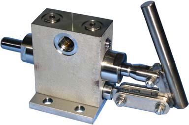
1 G & J SERIES HIGH FLOW SPOOL VALVES 1 /4", 3 /8" or 1 /2" NPT PORTS 3-WAY OR 4-WAY OPERATION PILOT AND SOLENOID OPERATED 2 AND 3 POSITION CONFIGURATIONS C V RANGE 1.7 TO 6.6 CONTROL LINE EQUIPMENT, INC Industrial Parkway Cleveland, Ohio (216) FAX: (216) Form # GJ-993


2 G Series 3-Way & 4-Way Valves Application Information Available in pilot and solenoid models only. These 1/4" NPTF port valves have self-aligning stacked spacers and O-rings, which assure O-ring seal while allowing increased air flow. These valves are ideal for high cycle applications and for operation of larger bore cylinders and air tools. The hard anodized, ground and polished spool increases valve life by resisting wear and corrosion while assuring start-ups without hang-ups. The ground and polished spool permits operation with no additional lubrication for a cleaner environment and reduced product contamination. The low profile aluminum body is lightweight and corrosion resistant. These valves are rated at 200 PSIG to 28" of mercury and will operate in high or low pressure or vacuum applications. All 4-way valves may be ordered with bottom ports for subplate or manifold mounting. Repair kits available. Class F coil is rated for 100% duty cycle. Standard features include a manual locking override and a pilot override. Override must be depressed and turned to operate. Feature / Benefit Information Standard external solenoid supply enables valve operation for vacuum service for low pressure operations. Remove and discard the pipe plug. Assemble the threaded plug. (part no plug kit, order separately), with o-ring assembled into the threaded port to block the internal supply connection. Connect the external air supply to the 1/8 NPTF port. PIPE PLUG INTERNAL AIR SUPPLY EXTERNAL AIR SUPPLY TUBE FITTING Air pressure (50 PSI minimum) introduced at the solenoid exhaust port (10-32 thread) will override the solenoid. This is a convenient way to setup and troubleshoot circuits without electrical power to the solenoids. Manual locking override is standard. Simply depress and turn the override button to shift the valve. PART NO PLUG SOLENOID VALVE W/INTERNAL SOLENOID SUPPLY FROM VALVE BODY AS SHIPPED CONVERTED SOLENOID VALVE W/EXTERNAL SOLENOID SUPPLY CONNECTION Specifications Lubrication: Valves are pre-lubed and can be operated without air line lubrication. If air cylinders or other air line devices require lubrication, ensure that lubrication oils are compatible with valve seals and of sufficient viscosity to assure adequate lubrication. Flow: 61.6 SCFM C v Factor: 1.72 Weights: Pilot.7 to 1.3 lbs. Solenoid 1.8 to 3.4 lbs. Minimum Pilot Pressure: Spring return 40 PSI Pilot return 20 PSI Standard Operating Pressure: Pilot Vacuum to 200 PSI Solenoid Vacuum to 150 PSI Temperature Range: -10 to 180 F 2
3 G Series Ordering Information Valve Model Series Letter G Body Style # Style 1 4-way side ported 4* 4-way bottom ported 5 3-way side ported *Gaskets and screws to mount valve on subplate or manifold included with valve. Order model sideported subplate or bottom ported manifold separately. Current Type* Letter Type A AC D DC N No Coil *Only required when ordering solenoid operated valves. Leave blank when ordering pilot valves. G S S A Valve Type # Type Port Size Actuator/Return Coil Voltage* 1 Two Position Detent 2 Two Position 3 Three Position Spring Centered All ports blocked in neutral 7 Three Position Spring Centered Inlet port blocked, cylinder ports open in neutral. # Size 2 1/4 NPT Letter Type PD Pilot/Pilot PS Pilot/Spring SD SP SS SN Solenoid/Solenoid (Available in 4-way only) Solenoid/Pilot Solenoid/Spring Solenoid/Spring normally passing (Available in 3-way only) # Voltage Volt DC Volt (AC or DC) Volt (AC or DC) Volt (AC or DC) Volt AC Volt AC 000 No Coil (N) *Only required when ordering solenoid operated valves. Leave blank when ordering pilot valves. Connector Accessories: CONSULT FACTORY FOR ADDITIONAL CONNECTOR OPTIONS Connectors without indicator lights or lead wire: CDN = 1/2" Conduit CSN = Strain Relief 4-Way Manifold Way Subplate /4 1-3/8 2-9/16 1/4 4" FOR 2 STATIONS 1/ /32 39/64 1-9/64 1-7/ / /16 3-9/ /64 3-1/16 2-9/16 1-9/16 2-1/16 1-9/ /4 9/16 7/16 1-1/4 1-3/8 5/16 3-3/ /64 5-1/8 5-1/8 1/4 1/4-18 NPTF. BOTH ENDS 1/4-20 UNC (3 PL) 27/64 3/16 DIA. (2 PL) 1/4 1/4-18 NPTF (3PL) 1/4 CAP SCREW WASHER, 1/2 29/64 1/4-18 NPTF (3 PL) 1/8-27 NPTF (2 PL) AND NUT (2 PL) 1/8-27 NPTF (2 PL) 1/4 29/32 13/64 DIA. (2 PL) (N0T FURNISHED) 29/32 1/4-18 NPTF (4 PL) 13/64 DIA. (2 PL) 29/64 3
4 G Series 4-Way Dimensions 4-Way Basic Valve /2 5 Port (Exhaust) 1 Port (Inlet) 3 Port (Exhaust) 1/2 1 7/8 1-3/4 1/2 1/2 4 Port (Cyl.) 2 Port (Cyl.) 1-3/4 1-1/4 1/4 3 Position, Cylinder Ports Open, Inlet Blocked Position All Ports Blocked Position Way Pilot 4-Way Single Solenoid 1/8-27 NPTF 1/8-27 NPTF 5-5/16 G212PD 29/32 Manual Override External Solenoid Supply 5-25/32 2 1/4 1-3/8 1/8-27 NPTF 2-15/16 2-1/2 G212SS-XXX-X G112PD 6-3/16 1/8-27 NPTF 1-25/32 1-7/16 3-1/4 7/ /4 3/4 Manual Override 2 External Solenoid Supply 5-5/16 1/4 29/32 1/8-27 NPTF 2-1/2 2-15/16 G212PS 29/32 3/8 5-25/32 1-3/8 7/ /4 3/4 G212SP-XXX-X 1/8-27 NPTF 5-5/16 1/8-27 NPTF 1/8-27 NPTF 1 3/4 29/32 G312PD G712PD 2-11/32 2-1/2 2-15/16 G212SD-XXX-X 6-3/4 4-Way Double Solenoid Manual Overrides External Solenoid Supply 7/ /4 6-7/16 1 3/4 1/4 1-15/32 1-7/16 3-1/4 2-1/2 2-15/16 G312SD-XXX-X G712SD-XXX-X 29/32 3/8 7/32 1-1/4 2 1/4 4
5 G Series 3-Way Dimensions 3-Way Basic Valve 2 Port (Cyl.) 3 Port (Exhaust) 1 Port (Inlet) 1 1-3/4 7/8 1/2 1/2 1-1/4 Valve Porting All Models. 2 1/2 2-1/2 1-1/4 1/ Way Pilot 3-Way Single Solenoid 1/8-27 NPTF 1/8-27 NPTF G252PD MANUAL OVERRIDE 1 EXTERNAL SOLENOID SUPPLY 7/32 G252SP-XXX-X 3/4 29/32 4-5/ /16 2-1/2 1/8-27 NPTF 1/8-27 NPTF G152PD 1 2 1/4 7/8 1/8-27 NPTF 5-3/ /32 1-7/16 3-1/4 4-5/16 MANUAL OVERRIDE 1 EXTERNAL SOLENOID SUPPLY 7/32 G252SS-XXX-X 3/4 1/8-27 NPTF 29/32 3/8 G252PS 2-1/2 2-15/16 1-3/8 4-25/ /4 1-3/8 4-25/32 MANUAL OVERRIDE EXTERNAL SOLENOID SUPPLY 7/ /16 3-1/4 3/4 2-15/16 2-1/2 1-15/32 3/8 G252SN-XXX-X 1 2 1/4 1-3/8 5-1/32 5

6 J Series 4-Way Valves Application Information Available in pilot and solenoid models only. The J Series valve has a self-aligned stacked O-ring spacer configuration which allow it to have one of the highest air flow capacities on the market. A ground and polished spool permits operation with no additional lubrication for a cleaner environment and reduced product contamination. These valves are rated at 150 PSI to 28" of mercury for operation in high and low pressure as well as vacuum applications. The anodized polished spool increases valve life by resisting wear and corrosion while assuring start-ups without hang-ups. All solenoid actuated models are furnished with Class F coils and external solenoid supply option. Coils can easily be interchanged or replaced by removing nut, sliding existing coil off, a new coil on. Position the coil connectors where you need them. Simply loosen nut and rotate coil to desired position. Molded connectors protect the electrical connections against high humidity and wet environments to meet NEMA 4 classification. Feature / Benefit Information Standard external solenoid supply enables valve operation for vacuum service for low pressure operations. Remove and discard the pipe plug. Assemble the threaded plug, (Part no plug kit, order separately), with o-ring assembled into the threaded port to block the internal supply connection. Connect the external air supply to the 1/8 NPTF port. General Specifications Air pressure introduced at the solenoid exhaust port (10-32 thread) will override the solenoid. This is a convenient way to set-up and troubleshoot circuits without electrical power to the solenoids. Lubrication: Valves are pre-lubed and can be operated without air line lubrication. If air cylinders or other air line devices require lubrication, ensure that lubrication oils are compatible with valve seals and of sufficient viscosity to assure adequate lubrication. Temperature Range: -10 to 180 F 6 Low profile die cast aluminum body is lightweight and corrosion resistant. PRESSURE MINIMUM PORT TYPE TYPE RANGE PILOT PRES. FLOW* C v SIZE ACTUATOR RETURN PSI PSI SCFM FACTOR Pilot or Vacuum To 10 3/8" All Solenoid for detent Vacuum To 3/8" All Spring** 20** Pilot or Vacuum To 10 1/2" All Solenoid for detent Vacuum To 1/2" All Spring** 20** *Flow capacity approximate. [90 PSIG supply, 75 PSIG outlet.] **Including 3-position spring centered. These valves require 50 minimum pressure.
7 J Series Valves Ordering Information Valve Model Series Letter J Body Style # Style 1 4-way side ported Current Type* Letter Type A AC D DC N No Coil *Only required when ordering solenoid operated valves. Leave blank when ordering pilot valves. J S S A Valve Type Port Size Actuator/Return Coil Voltage* # Type # Size Letter Type # Voltage 1 Two Position Detent 2 Two Position 3* Three Position Spring Centered 7** Three Position Spring Centered *All ports blocked in neutral **Inlet port blocked, cylinder ports open in neutral. 3 3/8 NPT 4 1/2 NPT PD PS SD SS SP Pilot/Pilot Pilot/Spring Solenoid/Solenoid Solenoid/Spring Solenoid/Pilot Volt DC Volt (AC or DC) Volt (AC or DC) Volt (AC or DC) Volt AC Volt AC 000 No Coil *Only required when ordering solenoid operated valves. Leave blank when ordering pilot valves. Connector Accessories: CONSULT FACTORY FOR ADDITIONAL CONNECTOR OPTIONS Connectors without indicator lights or lead wire: CDN = 1/2" Conduit CSN = Strain Relief 4-Way Basic Valve Dimensional Data Valve Porting Two Position PORT (EXHAUST) 1 PORT (INLET) 3 PORT (EXHAUST) 3-1/16 1/8-27 PILOT PORT 4 PORT (CYL) 2-5/8 2 PORT (CYL) 1/8-27 PILOT PORT /32 3-5/32 3-5/8 All Ports Blocked. 2 4 Three Position Valves Cylinder Ports Open /32 1-3/4 1-3/4 2-5/16 1-3/4 MTG. HOLES 1/4 5/16 DIA. 6-3/
8 J Series 4-Way Dimensions 4-Way Pilot S 14 PORT (PILOT) 2-5/8 S 12 PORT (PILOT) S 14 PORT (PILOT) 2-5/8 7-7/8 3/4 9-3/16 2-1/16 J21XPD J21XPS J11XPD J31XPD J71XPD EXTERNAL SOLENOID SUPPLY 4-Way Single Solenoid MANUAL OVERRIDE 2-5/8 S 12 PORT (PILOT) J21XSP-XXX-X 3/4 1-7/16 4-7/32 7-7/8 3/4 MANUAL OVERRIDE 2-5/8 J21XSS-XXX-X 9-3/16 2-1/16 4-Way Double Solenoid MANUAL OVERRIDES EXTERNAL SOLENOID SUPPLY J21XSD-XXX-X 3/4 1-7/16 4-7/32 7-7/8 3/4 MANUAL OVERRIDES J31XSD-XXX-X J71XSD-XXX-X 9-3/16 2-1/16 8
9
10
11
12
13

14
15

16
 433-7766 FAX: (216) 433-7664 Form #")
17 PNEUMATIC COUNTERS PRE-DETERMINING OR TOTALIZING TYPE COUNTERS CONTROL LINE EQUIPMENT, INC Industrial Parkway Cleveland, Ohio (216) FAX: (216) Form # PC-693
. 4.")

18 Select-A-Count Pneumatic Programmer WHAT IT DOES 1. COUNTS air signals delivered to the SAC STORES and accumulates the count information indefinitely. Upon receipt of the last count signal, a built in valve opens the separate air supply to the outlet port and DELIVERS this air to perform work function(s). 4. RESETS automatically for another cycle only when the last count signal is released (exhausted). HOW IT WORKS Each count signal operates a ratchet piston which advances a 24 tooth circular gear by one tooth. When the last count signal is received, a pin in the circular gear operates an internal 1/8" 3-way N/C valve supplying air to the OUT port. This 3-way valve also operates a second piston which allows the circular gear to return to the start position for another cycle when the last count signal is released (exhausted). REPEATABILITY AND RELIABILITY Proper lubrication, correct pressures and CRISP COUNT SIGNALS are the keys to trouble free service and multi-million cycle life. Weak or erratic count signals may prevent a proper count. Slow exhaust of a count signal can be corrected by installing a quick exhaust valve with a close nipple, to the count port. PORTS (ALL): 1/8 NPT COUNTS PER SECOND: up to 2-1/2 (including reset time) OUT SIGNAL (CFM): multiply PSI by.22 ( PSI) WEIGHT: 4 pounds FINISH: black anodized aluminum MOUNTING: It is recommended that the SAC-24 be mounted with the oil hole up. LIFT TO RESET THIS END UP OIL (10 DROPS) ONCE A WEEK AIR SUPPLY P.S.I. COUNT FROM 3 WAY P.S.I. 2-3/8 OUT 1/8 4-1/2 EXH 3-11/16 1 OFF / /64 2-7/8 DIA. 2 DIA. 1-1/2 5/8 3/4 1-13/32 2-5/64 #10-32 UNF x 1/2 DEEP 2 PLACES ON 3-3/8 DIA. 3-3/8 #10-32 UNF x 1/2 DEEP 2 PLACES ON 3-3/8 DIA. 3-1/2 2


19 IMPULSE COUNTERS DESCRIPTION Model AC-6 is a six digit totalizing counter. A pneumatic* signal or impulse, exhausted to atmosphere between inputs, advances the counter one digit each time signal is present. The counter is useful for event recording, piece or part counting or cycle counting. This counter can be used in general counting applications where mechanical or electrical drives are impractical or inconvenient. It is ideal where the surrounding atmosphere prohibits the use of the other types of counting devices. The count is maintained until manually reset. SPECIFICATIONS 9/32 MTG. HOLE (2) PLACES SIGNAL PRESSURE RANGE: 25 to 125 PSI MAXIMUM COUNT SPEED: 300 counts per minute TYPE: six digit count-up totalizer MOUNTING: thru hole base mounting - orientation is not critical 2 1-5/8 RESET: manual reset knob returns display to zero WEIGHT: 14 ounces CONSTRUCTION MATERIALS: anodized aluminum, case hardened steel and acetal plastic 3/16 RESET KNOB 4-1/8 4-1/2 1/8-27 NPT SIGNAL PORT 3/16 * Consult factory for hydraulic service. 1-5/8 2 3/8 HOW TO ORDER: ORDER AIR COUNTERS BY MODEL NUMBER: SAC-24 for a Select-A-Count AC-6 for a Totalizer 3
20 CONTROL LINE EQUIPMENT, INC Industrial Parkway Cleveland, Ohio (216) FAX: (216) DISTRIBUTED BY:
21 Series 12 Veritrol Hydraulic Checking Cylinder Model Specifications Operating Air Pressure: 60 p.s.i. minimum, 150 p.s.i. maximum. Application Information Provides uniformly controlled stroke speed essential to tool or work piece feeding on drilling, milling, cut-off and grinding. Smooths out stroke variations caused by compression of air under irregular loads. Can be connected to feed table or other driven machine part, or any arrangement where checking stroke opposes air-cylinder work stroke. Available in single or double acting models, providing up to 2,000 lbs. checking capacity in either or both directions. Dial set speed control permits cylinder travel from 3" to 300" per minute. Oil reservoir indicating stem gives visual refill cue. Skip Control: Valve is normally open. To obtain speed control, skip valve must be actuated by applying a 60 p.s.i. minimum air pilot signal to the 1/8-27 NPTF port. Stop Control: Valve is normally open. To stop piston rod movement, stop valve must be actuated by applying a 60 p.s.i. minimum air pilot signal to the 1/8-27 NPTF port. NOTE: On cylinders equipped with skip & stop control valves, both skip & stop valves must be actuated to stop piston rod travel. Ordering Information SERIES CYLINDER TYPE NO. TYPE 0 Single Acting, Retract Checking 1 Single Acting, Extend Checking 2 Double Acting MOUNTING STYLE NO. STYLE 9 Basic Cylinder STROKE LENGTH NO. LENGTH 020 2" 040 4" 060 6" 090 9" " " " EXTEND CONTROLS NO. CONTROL 0 No Skip, No Stop 1 Skip Only (N/A with Single Acting Retract) 2 Stop Only (N/A with Single Acting Retract) 3 Skip & Stop (N/A with Single Acting Retract) RETRACT CONTROLS NO. CONTROL 0 No Skip, No Stop 1 Skip Only (N/A with Single Acting Extend) 2 Stop Only (N/A with Single Acting Extend) 3 Skip & Stop (N/A with Single Acting Extend) ROD PROJECTION OPTION For additional Rod Projection specify total length of Rod Thread desired as an E = dimension after the Model No. EXAMPLE: Where 6" additional Rod Thread is desired: , E = 9-3/8" (std. E of 3-3/8" + 6" = 9-3/8"). Model 1579 Hydraulic Oil Fill Kit Recommended for use in filling oil reservoir in Series 12 cylinders. CONTROL LINE Hydraulic Oil Recommended especially for use in Control Line Series 12 Veritrol hydraulic checking cylinders. QUANTITY PART NO. 1 Gallon 1626 Form# National FLUID POWER Association MEMBER
22 Series 12 Veritrol Dimensional Information EXTEND CONTROLS Opt. Skip Valve (1/8-27 Ports) Opt. Stop Valve (1/8-27 Ports) RETRACT CONTROLS Opt. Skip Valve (1/8-27 Ports) Opt. Stop Valve (1/8-27 Ports) 1 Speed Control Speed Control 1-5/8 1/4-20 x 3/8 Deep Thd. 4 Pl. 1/2 1-7/32 1-1/4 Stroke + 2 Stroke + 15/16 Mtg. Hole For 1/4 Screw. 6 Pl. With Skip or Stop Option Bleed Screw ±.002 Filler Plug Without Option 7/16 20 Thd. 2-3/ /32 1-1/2 Sq. 15/32 E B 1/8 Stroke /32 Stroke + D C 7/32 Reservoir Vent Indicating Stem Repair Kit SERIES 12 NO. All Models Model XX9-XXX (shown) Model X09-XXX (same dimensions less retract controls) Model X9-XXX (same dimensions less extended controls) Dimensions Stroke Length Inches REF. B 4 4 C 3-15/ /32 D Stroke /8 Stroke /4 E 3-3/8 3-3/8 Mounting Capabilities Common front flange mount with checking cylinder working in tandem with air cylinder. Flush mounted with checking cylinder opposing air cylinder. CONTROL LINE EQUIPMENT, INC Industrial Parkway Cleveland, Ohio (216) FAX: (216)
23 Series 13 Coaxial Air / Hydraulic Cylinder MODEL Specifications Operating Air Pressure Controlled Speed Either Direction Effective Piston Area Skip & Stop Valve Operation Skip Operation Stop Operation CONTROL LINE EQUIPMENT, INC Industrial Parkway Cleveland, Ohio (216) FAX: (216) Application Information Unique combination cylinder provides smooth, precise hydraulic control, but requires only a shop air supply. Oil cylinder concentric with air cylinder, results in unit about one-half the length of an in-line unit, and easier to install than side-by-side cylinder combination. These cylinders recommended for machine tool applications or work-piece feeding, and where precise speed control and smoothness are required. The compactness of the Series 13 is beneficial where long stroke length, with controlled and uniform speed throughout the stroke, is desirable. Dial-set, stepless, load-compensated, speed control in both directions assures smooth, uniform piston travel regardless of load fluctuations. Oil reservoir automatically compensates for volume changes with visual low-oil signal. Optional built-in skip-stop control for selection of rapid traverse or stop in either direction. 30 p.s.i. minimum, 150 p.s.i. maximum. 3 inches per minute minimum, 300 inches plus 60 inches or minus 40 inches maximum. 4.6 square inches extending 3.14 square inches retracting. A 60 p.s.i. minimum air pressure is required on coaxial cylinder operating at from 30 to 70 p.s.i. Cylinder pressures above 70 p.s.i. require a skip or stop valve pressure equal to 85% of operating pressure. Pressurizing Skip Port opens Skip Valve allowing speed control to be bypassed, either direction. Pressurizing Stop Port closes Stop Valve causing cylinder to immediately stop, in either controlled or skip feed modes. HOW TO ORDER: Refer to the table below and specify Series-And-Bore Number. Select suffix number indicating Cylinder Type, Control Option and Mounting Option. Add Stroke Length. This will produce a 4-digit prefix, 4-digit suffix and a dimension in inches. See typical model number beneath illustration above. Ordering Information Series & Bore No. No. Bore /2" Control Option No. Type 20 No Skip or Stop 21 Skip Only 22 Stop Only 23 Skip & Stop Rod Thread No. Type 0 3/4-10 UNC 2 3/4-16 UNF 3 No Thread Mounting Styles No. Style 0 Flush Mount 1 Low L 3 Front Flange 4 Rear Flange Available Stroke Lengths No. Stroke 030 3" 060 6" 090 9" " " " " " " FORM COAX 398 National FLUID POWER Association MEMBER
24 Series 13 Coaxial Cylinder 3 Speed Control (Shaft Extend) Bleed Screw 1 1-1/2 47/64 2-5/8 1-1/2 1-3/16 Stroke + A Stroke + 1-1/32 Cyl Ports 1/4-18 NPTF Filler Plug 2-9/64 7/16 L Flush Mount 2-3/8.80" Dia. 1/2 1-1/2 1-1/2 1-1/2 2-3/8 Speed Control (Shaft Retract) 3 1-1/2 Dia. 1/4 Stroke + B 2-1/4 Dia. 1/4-20 UNC-2B, TYP Vent Hole, On Opposite Side Bleed Screw 5/16 3 Front Flange Mount Rear Flange Mount 2-3/16 3/8 Dia. Hole, Typ 3/8 Dia. Hole, Typ 2-3/16 1-1/ /8 4-5/8 2-1/4 3/8 Stroke + D 2-5/8 Stroke + D 3/8 4-5/8 3-7/8 L Mounts Skip And Stop 3-47/64 3/8 1-1/32 1/8-27 NPTF Skip Or Stop 3/8 2-45/64 1/8-27 NPTF 2 1/2 2-3/8 9/32 Dia. Hole, Typ 5/16 5/8 Stroke + C Skip Stop Skip or Stop Dimensions Model Stroke Range A B C D L Up to 9" 8-1/4 7-25/ /32 8-5/8 1-9/32 No Skip Over 9" to 18" 9-3/4 9-9/ / /8 2-1/32 Or Stop Over 18" to 27" 11-1/ / / /8 2-25/32 Up to 9" 8-13/ / /32 9-3/16 1-9/32 With Skip Over 9" to 18" 10-5/ / / /16 2-1/32 Or Stop Over 18" to 27" 11-13/ / / / /32 Up to 9" 9-27/32 9-3/8 11-1/8 10-7/32 1-9/32 With Skip Over 9" to 18" 11-11/ /8 12-5/ /32 2-1/32 And Stop Over 18" to 27" 12-27/ /8 14-1/8 13-7/ /32 Stroke Force Information Air Line Extending Retracting Pressure PSI (bar) Force Lbs. Force Lbs Repair Kit SERIES 13 NO. All Units 7153 Model 1579 Hydraulic Oil Fill Kit Recommended for use in filling oil reservoir in Series 12 and Series 13 cylinders. Hydraulic Oil Recommended especially for use in Control Line Series 12 Veritrol hydraulic checking cylinders and Series 13 Coaxial air-hydraulic cylinders. QUANTITY PART NO. 1 Gallon 1626 CONTROL LINE EQUIPMENT, INC Industrial Parkway Cleveland, Ohio (216) FAX: (216)


25 HYDRAULIC HAND PUMPS SERIES 500/ INDUSTRIAL PARKWAY Cleveland, Ohio Phone: (216) Fax: (216)
26 SINGLE STAGE PUMPS The series 500/50R modular hydraulic hand pumps are designed for use with an external hydraulic reservoir in a wide variety of demanding applications. The 500 series pumps are designed for use in systems, which utilize an external relief valve. The 50R pumps incorporate an integral, factory set, tamper resistant relief valve for those applications where external relief is impractical or undesirable. STANDARD FEATURES INCLUDE: * All steel construction for rugged use. * Rod wiper (except 1-1/2" bore) to exclude dirt. * All o-ring seals no fiber or metal seals to leak. * Self-retained release screw, which cannot be accidentally removed. * Capable of operating in any mounting orientation. * Heat treated pins and linkages for extended life. * Ground pistons to prevent seal extrusion. * Nitrotec treated pistons for corrosion resistance. OPTIONAL FEATURES INCLUDE: * Optional seals for pumping alternate fluids. * Manifold mounting for inlet and/or outlet. * Operating handle length 18 or 36 inches for various handle forces. * Custom designs for your particular application requirements. Single Stage Example: Series: 500=Without Relief 50R=With Relief Bore: Inches in Eights E 24 XXXX Relief Setting PSI omit for 500 Series Handle Length: 24" is standard Model Number Maximum Rated Pressure Piston Diameter Cubic Inches/Stroke 2 Seals: B=Buna, V=Viton, E=EPR 18" Handle Force per 100 PSI 24" Handle Force per 100 PSI 36" Handle Force per 100 PSI ,000 3/ ,000 1/ ,000 5/ ,500 3/ , , / Weight - WARNING - NO internal relief valve is supplied with these pumps unless ordered as an OPTION. Therefore, for safety purposes, it is necessary to plumb a relief valve, on the outlet of these pumps, which is appropriately set below the lowest maximum rating of any system component.
27 Two Stage Example: Series: 550=Without Relief 55R=With Relief TWO STAGE PUMPS Low Pressure Bore in Eights High Pressure Bore in Eights The series 550/55R two-stage modular hydraulic hand pumps are designed for use with an external hydraulic reservoir. The two-stage, or "HI-LOW", feature allows the operator to displace a larger amount of fluid at lower pressures. It automatically shifts over to a smaller displacement for higher pressures. This feature dramatically reduces cycle times, and number of strokes required, for many applications. The 550 series pumps are designed for use in systems that utilize an external relief valve. The 55R series pumps incorporate a factory set, tamper resistant relief valve for those applications where an external relief is impractical or undesirable. STANDARD FEATURES INCLUDE: * All Steel construction for rugged use. (The low-pressure tube is hard coat anodized aluminum) * All o-rings no fiber or metal gaskets to leak. * Self-retained release screw that cannot be accidentally removed. * Heat-treated pins and linkages for extended life. * Ground pistons to prevent seal extrusion. * Nitrotec treated pistons for corrosion resistance. * 500 psig standard cross-over between large and small bores. OPTIONAL FEATURES INCLUDE: * Optional seals for pumping alternate fluids. * Manifold mounting for inlet and/or outlet. * Operating handle length 18 or 36 inches for various handle forces. * Custom designs for your particular application requirements B 24 XXXX Relief Setting PSI Omit for 550 Series Handle Length: 24" is standard Seals: B=Buna, V=Viton, E=EPR Model Number Maximum Rated Pressure Low Pressure Piston Diameter High Pressure Piston Diameter Cubic Inches/Stroke Low Pressure High Pressure Weight /2 1/ /2 5/ /2 3/ WARNING - NO internal relief valve is supplied with these pumps unless ordered as an OPTION. Therefore, for safety purposes, it is necessary to plumb a relief valve, on the outlet of these pumps, which is appropriately set below the lowest maximum rating of any system component. 3
28 TANDEM PUMPS Tandem configuration pumps combine any two modular pumps into a single unit. This configuration can yield up to three different displacements and is available with common or separate inlets and outlets. Reservoirs and mounting plates can be added to complete the package. All of the same standard and optional features from the 500/550 series are included in the tandem pumps. A special handle assembly is provided as standard to operate both pumps or just one. Triple and quadruple units are also available consult the factory for details. ORDERING INFORMATION 2 XXX XXX B 24 XXXX TANDEM PUMP #1 SIZE HANDLE 18", 24" or 36" RELIEF SETTING OMIT FOR NO RELIEF PUMP #2 SIZE SEALS: B=BUNA V=VITON E= EPR Standard sizes are 030 for 3/8, 040 for 1/2", 050 for 5/8", 060 for 3/4", 080 for 1", 120 for 1-1/2", are for two stage configurations. Any two size pumps can be combined, maximum pressure rating is a function of the final configuration, consult engineering for rating. When operated together the displacements and handle forces are cumulative, add for total displacement and force. Standard configuration is for a common inlet and common outlet, if required a common inlet with separate outlets is available consult factory. 4
29 FOOT OPERATED PUMPS The 60R/65R Series foot operated hydraulic pumps extend the range of operation for those applications where a hand pump is not ergonomic or practical. Any of the single stage pump 1/2" bore and greater or two-stage pump configurations can be incorporated into the foot pump and where necessary a reservoir can be included to complete the package. As standard the foot-operated pump utilizes one pedal to pump and a separate pedal to release pressure. A relief valve is also standard for foot-operated pumps. Displacements are the same as hand operated pumps, pedal forces and maximum rated pressures are shown below. ORDERING INFORMATION 6 XX XXXB - FF XXXX FOOT PUMP RELIEF SETTING FOOT OPERATED BOTH PEDALS PUMP TYPE 0R = SINGLE STAGE 5R = TWO-STAGE PUMP SIZE: 040 = 1/2" 124 = 1-1/2 X 1/2 050 = 5/8" 125 = 1-1/2 X 5/8 060 = 3/4" 126 = 1-1/2 X 3/4 080 = 1" 120 =1-1/2 SEALS: B=BUNA V=VITON E= EPR MODEL NUMBER MAXIMUM RATED PRESSURE PISTON DIAMETER PEDAL FORCE PER 100PSI WEIGHT 60R / R / R / R R /2 7 65R /2 x 1/2 x R /2 x 5/8 x R /2 x 3/4 x
30 PUMP & RESERVOIR ASSEMBLIES The unique all bolt together construction of Control Line pump and reservoir assemblies offer the design engineer the most flexible package to meet most all application needs. Any of the single stage or two-stage pumps can be incorporated, as standard, tandem pumps with reservoirs are available as special order products. The all steel modular construction extends the heavy duty, rugged construction of the pumps into the complete hydraulic power source. Since the units bolt together we can modify any one of the components to meet your application requirements while utilizing standard parts for overall cost savings. "L" = 7-3/4" for the 80 cubic inch reservoir and 13-1/2" for the 160 cubic inch size, consult the factory for custom size reservoir requirements. ORDERING INFORMATION 1 XXX XXX X B 24 XXXX PUMP & RESERVOIR PUMP TYPE 500, 50R, 550, 55R, 60R, 65R PUMP SIZE 030,040,050,060,080,120,124,125,126 RELIEF SETTING OMIT FOR NO RELIEF HANDLE 18", 24", 36" OR "FF"FOR FOOT PUMP SEAL TYPE B= BUNA, V=VITON, E=EPR RESERVOIR CAPACITY A= 80 Cubic inch, B= 160 Cubic inch, X= Special Standard units are shipped without oil and unpainted. Units should be mounted with the fill plug up as shown, the vent screw must be open during operation to prevent malfunction. 6


31 MODIFIED PRODUCTS The hand pump with integral 4-way directional control valve incorporates a near zero leak shear seal manual type valve. The 4-way valve can control double acting cylinders or two separate cylinders from one pump. This style of pump can also include a reservoir and base plate to complete the hydraulic power package. There are several configurations for the 4-way including open center, closed center and tandem center. Contact our engineering department with your application specifics. The integrated package shown at the right is an example of a standard pump manifold mounted to a custom base plate and special reservoir. Completing the package is a twostage telescopic cylinder assembly. Since the assembly bolts together any one of the components could be changed to a different unit to create a new configuration for similar applications. The modular building style also makes service easier for the field personnel. The modified pump shown on the left was designed to meet challenging specifications for a customer that required a custom adjustable operating handle interface, non-standard port sizes and a special design for the release screw. We are able to incorporate all of the customer requirements into the final unit so that no field modifications are needed. This saves OEM and user customers both time and money. The package shown at the left is a modified pump and reservoir assembly. The customer needed a mount for mount interchange for an existing unit, so we provided a custom base plate, reservoir and also provided them with special plating on the linkage assembly. Our package reduced the number of strokes required for their application by 75%, improving overall efficiency. 7


32 CUSTOM PRODUCTION The pump shown on the left is a custom built all Stainless Steel, double acting unit built for use on offshore equipment in a marine environment as the emergency power source used to open or close watertight passage doors. This pump features a displacement of over 4 cubic inches per complete stroke and is rated for 1000PSI service. Oversize internal passages and ports allow for maximum fluid displacement in an application where output flow is critical. The pump on the right is a special fluid transfer style unit made from aluminum and zinc plated steel. Designed for use in transferring fluid from a portable fluid service cart to the reservoirs onboard mobile equipment. The handle force, displacement and seal compatibility are key to this type of application. CONSULT THE FACTORY AT THE NUMBERS BELOW FOR OTHER CUSTOM UNITS DISTRIBUTED BY: CONTROL LINE EQUIPMENT, INC INDUSTRIAL PARKWAY CLEVELAND, OHIO (216) FAX: (216) sales@control-line.com FORM #0404HHP

33 Series 900 Clamping Cylinders Model 921 Application Information Single acting, spring return cylinder available in 2", 3" or 4" bore sizes in 1" and 2" stroke lengths. Cast aluminum body is corrosion resistant. Body is designed for horizontal or vertical mounting. Slotted mounting holes permit fast and easy installation or relocation. For air service up to 150 PSI. Stress proofed steel chrome plated piston rod. Available with threaded and non-threaded piston rods. Ordering Information: Select three digit model number which pertains to bore and stroke from chart below. Models L T Typ. Models H K J L M N Typ. P Q 5/8 Dia. K M R Typ. S 3/4 A A B Typ. T Typ. R Typ. S Repair Kits J H 3/4 A 1/16 G F E D A N Typ. B Typ. P Q T Typ. Models H K F G J E L M N Typ. P Q MODELS NO. 921, 922, 923, , 932, 933, , 942, 943, Dimensions R Typ. S 3/4 A G F E C A B Typ. Typ. Non- Th d. Th d. Bore Rod Rod Dia. Stroke Spring Model Model In. In. Force H J K L No. No. Lbs. A B C D E F G Dia. Dia. Th d. NPTF M N P Q R S T /8 1-3/ /8 3-3/4 4-3/4 1-1/4 2-3/8 1/2-13 1/ /64 27/32 1-9/32 3-7/32 2-5/8 3-5/8 9/ /8 1-3/ /8 4-3/4 5-3/4 1-1/4 2-3/8 1/2-13 1/ /64 27/32 1-9/32 3-7/32 2-5/8 3-5/8 9/ /2 1-1/4 2-1/16 2-3/8 4-3/16 5-3/16 1-3/8 3-3/8 1/2-13 1/ /32 1-7/ / /32 3-5/8 4-7/8 13/ /2 1-1/4 2-1/16 3-3/8 5-3/16 6-3/16 1-3/8 3-3/8 1/2-13 1/ /32 1-7/ / /32 3-5/8 4-7/8 13/ /2 1-11/ / / / /2 3/4-10 1/4-18 3/4 1-3/8 2-3/8 5-5/ /16 6 7/ /2 1-3/16 2-5/8 3-23/ / / /2 3/4-10 1/4-18 3/4 1-3/8 2-3/8 5-5/ /16 6 7/16 CONTROL LINE EQUIPMENT, INC Industrial Parkway Cleveland, Ohio (216) FAX: (216) Form# National FLUID POWER Association MEMBER

34 SERIES F FEED CONTROL Smooth control of air cylinders and other linear motions Website: sales@control-line.com

35 SERIES F FEED CONTROL General Information The Series F Feed Control is a closed-circuit, self-contained hydraulic metering device. When mechanically coupled to some other linear motion, it provides an accurate, determinable, and smooth feed rate for the device being controlled. The feed rate can be varied as required by adjusting the metering device in the closed system. It especially provides an economic solution to the long-standing problem of controlling air cylinders. Because of air s compressibility, precise control of air cylinders, by themselves, is not possible in many applications. Therefore, expensive alternate hydraulic or mechanical systems had to be used, despite the basic advantages of air circuitry: low cost, easy maintenance, and almost universal availability of air supply. The Feed Control has followed the established Control Line tradition of superior design for the maximum in reliability and lowest level of maintenance. Some of the design specifications and features that assure operating reliability are: Block-Vee dynamic seals to help achieve leak free service. 2 piece construction and rod assembly consists of a 5/8 piston rod and a 7/16 threaded stud, offering greater resistance to rod shearing than is available in single unit constructions. The piston rod is hard chrome plated to prevent shaft nicks and scratches which could damage seals and result in leakage. Hard coated aluminum tubing resists scoring and potential seal damage and resultant leakage. Extra long nonmetallic reinforced PTFE rod and piston bearings provide exceptionally long life to all moving parts. The sealed compensator assembly consists of compressible rubber discs which expand and contract with the flow of oil, obsoleting the need for a compensator piston and rod assembly. Valve Options Skip Feed and Stop Feed valves provide additional speed control features to the basic Feed Control and consist of either an air pilot operated or solenoid operated valve. A minimum operating air pilot pressure ot 35 PSI is required by both valves, although up to 80 PSI may be needed tor high speed, high cycle applications. The valves are mounted on the side of the unit with the feed rate adjustment incorporated into the valve stack. A calibrated adjustment knob is standard on all Feed Control models with optional valving. See the illustrations on the back cover. Stop Feed A Stop Feed valve allows a Feed Control to be halted at any point of its controlled feed, dwell and then restart. Mounted in front of, and in series with the adjustable orifice, the stop valve blocks the internal flow of fluid when activated. Deactivating the valve opens the flow path and the unit continues its slow controlled feed. The stop valve does not affect flow through the piston and cannot stop the unit during rapid return. Skip Feed The Skip Feed uses the same valves as the Stop Feed, but changes their position and the internal flow path. Mounted behind the adjustable orifice and parallel to it, the Skip Feed valve bypasses the restriction and allows free flow when deactivated. When activated, the free flow path is blocked and the fluid is forced through the adjustable orifice, putting the unit back into controlled feed. Skip-Stop Feed Both Skip Feed and Stop Feed valves can be combined on a single Feed Control. Multiple feed rates can be obtained by adding skip valves and adjustable orifices to the valve stack. The stop function can be added by placing a valve in front of the adjustable orifice. Double feed units require a separate valve stack to control the feed in each direction. Forward Feed Model The piston for the forward feed unit has a flapper style check valve which is held closed when the piston moves forward. This closes the passageways in the piston and forces the oil through a restrictive orifice which controls the feed rate. When the piston is retracted, fluid pressure opens the check valve and oil flows freely through the piston. Reverse Feed Model The reverse feed model is the exact opposite of the forward feed. When the piston is moved forward, the check valve opens and the piston moves without restriction. In the opposite direction, however, the valve closes and oil is again forced through a restrictive orifice to control the feed rate. The restrictive orifice is located in the rear block of the reverse feed unit. Double Feed Model A double feed unit is used whenever the feed rate must be controlled in both directions. The piston on this type of Feed Control does not have any passageways and always forces the oil to flow through a restrictive orifice. However, since different feed rates may be required in each direction, a double feed unit utilizes two restrictive orifices with separate adjustments and internal check valves to ensure independent operation in each direction. The restrictive orifices and flush adjusting screws are located in either end of the unit.
36 Design Features Maximum Feed Rate / minute* Minimum Feed Rate / minute Maximum Thrust ,000 lbs. Maximum Operating Temperature F Maximum Creep, Stop Valve Activated** first minute.010 after five minutes * Maximum speed is a function of thrust, and is limited by temperature rise, and valving configuration. ** Powered by 2.5 inch bore cylinder at 80 psi lb. thrust version available. Consult factory. PISTON ROD SPEED INS/MIN Temperature Limitation Curve Thrust vs. Feed Rate Independent Mounting Control Line s Feed Control can be mounted directly to a machine by means of the front nose mount or with the optional clevis. As with any cylinder application, care should be taken to ensure proper alignment between the unit and the machine to prevent excessive wear. Parallel Coupling A Feed Control can also be mounted on top of a cylinder and connected by a mounting plate and tie bar. Because of the opposing offset forces, a bending movement is created when using parallel coupling. A special effort should be made so that the machine absorbs most of the bending movement. To accommodate the mounting plate and tie bar, all Control Line cylinders require a special rod extension when parallel coupled to a Feed Control. The required dimensions tabulated below are automatically supplied when a parallel coupled Feed Control/cylinder unit is ordered. SERIES B Bore Size A C 1-1/ , 2-1/ /4, 4, SERIES D Model A C 12, , 49, , THRUST (LBS.) Construction End Plates Aluminum Piston Rod Chrome Plated Steel Cylinder Tube Hard Coated Aluminum Reservoir Tube Thermoplastic Rapid Traverse Nuts Steel Rod and Piston Bearing PTFE Seals Block Vee, Buna-N Valve Blocks Aluminum Speed Control for Linear Motion Control Functions A Feed Control includes many standard features which allow easy adaptation to almost any given set of control requirements. Three different models are available to satisfy the need for forward, reverse or double feed operation. Each model uses a different piston and valving arrangement to regulate the flow of oil. If only a portion of the cycle needs to be controlled, rapid traverse nuts permit rapid advance. By turning the flush adjusting screw, the unit may be calibrated to provide the exact feed rate required and, for applications which require the unit to stop, skip, or a combination of both, optional valving is also available. Tandem Coupling With tandem coupling, the Feed Control is connected to the back of the cylinder and the two piston rods are joined together. While this mounting method eliminates the bending movement, it also necessitates the use of a skip valve for rapid traverse. This mounting method is also available with Control Line s Series B or Series K cylinders. Feed Control stroke must be at least equal to cylinder stroke. Feed Rate Adjustment The restrictive orifice which controls the feed rate consists of a small needle valve. Turning the flush adjusting screw raises or lowers the needle to either open or close the orifice. And since flow passes through an orifice at fixed rate at a given pressure, the feed rate can be precisely controlled. The adjusting screw is located in the head on forward feeds, the cap on reverse feeds, and in both locations on double feeds. An Allen screw is utilized to adjust the feed rate, however if adjustment must be made frequently, an optional calibrated knob is available for accurate resetting. SERIES K Bore Size A C 1-1/ , 2-1/ /4, 4, Rapid Traverse Adjustment Rapid traverse is the ability to engage a Feed Control at any point in the cycle without using external valving. This is accomplished through the use of an extended, threaded piston rod and rapid traverse nuts, both of which are standard on all Feed Control units. Optional lengths are shown on the back cover. A tie bar which moves freely along the extended piston rod is securely fastened to the machine member being controlled. This allows the machine and the tie bar to move freely without engaging the Feed Control. The rapid traverse nuts are then positioned so that the tie bar strikes them at the point where the feed rate needs to be controlled. The machine s feed rate would then be regulated by the Feed Control.
37 How to Order Specify: 1. Quantity 2. Model Number F8323 Forward Feed R8323 Reverse Feed D8323 Double Feed 3. Stroke Length -2, -4, etc. 4. Valve Options -sk Skip Feed -st Stop Feed -sk/-st Skip/Stop Feed (On double feed units, specify what control is needed in which direction.) 5. Valve Operator -E Solenoid operated (specify voltage) 6. Mounting Kits -Specify if factory assembly is required Parallel Coupling (specify cylinder model) Tandem Coupling (specify cylinder model) 7. Accessories -CB Factory assembled clevis mount Standard Feed Stroke A B Y Net. Weight 1-1/ /8 3-5/16 6.1# /8 3-5/ /8 4-7/ /8 5-1/ /8 7-3/ /8 10-9/ / / / / / / Oil Filling Kit Feed Control Oil -CK Calibrated Knob AIR PILOT VALVE OPTION Bore Size ZB 1-1/2 8-17/ /32 2-1/2 8-21/32 3-1/4 9-25/ / / /32 SOLENOID OPERATED VALVE OPTION SERIES B CYLINDER TANDEM-COUPLED TO F8323 CONTROL * Add cylinder stroke and feed stroke to ZB dimension to obtain overall length to shoulder of piston rod. Standard ZB dimension applies only to Series B cylinders with standard rod diameter and standard C rod extension. CONTROL LINE EQUIPMENT, INC Industrial Pkwy. Cleveland, Ohio (216) Fax (216) Website: sales@control-line.com

 433-7766 FAX: (216)")
38 BRASSLINE CYLINDERS 3/8" TO 2" BORES 6 MOUNTING STYLES MOUNTING ACCESSORIES 250 PSI AIR, 500 PSI HYDRAULIC SPECIAL CONFIGURATIONS AVAILABLE National FLUID POWER Association MEMBER CONTROL LINE EQUIPMENT, INC Industrial Parkway Cleveland, Ohio (216) FAX: (216) Form #B0500
39 B D plus stroke E F H G C J dia. A B K L I dia. Two Model Numbers Places Single Double Bore A B C D E F G H I J K L Acting Acting 3/8" 3/ NF 9/ /16* 7/32 9/16 7/64 5/ /16 1/2-20NF 10-32NF /2" 9/ NF 3/4 1-11/16* 7/32 9/16 7/64 5/ /16 1/2-20NF 10-32NF /4" 11/16 1/8-27NPT /32* 19/64 19/32 7/ /4 5/8-18NF 1/4-28NF " 1 1/8-27NPT 1-1/4 1-31/32 19/64 19/32 7/ /16 5/8-18NF 5/16-24NF /8" 1-1/8 1/8-27NPT 1-3/8 1-31/32 19/64 19/32 7/ /16 5/8-18NF 5/16-24NF /2" 1-1/2 1/8-27NPT 1-3/4 2-5/8 3/8 13/16 3/ /2 1-14NF 1/2-20NF " 1-3/4 1/4-18NPT 2-1/4 2-5/8 3/8 1 3/16 1-7/ /8 1-1/4-12NF 5/8-18NF Note: For Single Acting Spring Return Cylinders Add To Base Length *1" For Strokes 0" to 1-1/4" 1-1/2" For Strokes 0" to 2" *1-1/2" For Strokes 1-5/16" to 4-1/4" 2" For Strokes 2-1/8" to 4" *2" For Strokes 4-5/16" to 5-1/4" (3/4" Bore only) 3" For Strokes 4-1/8" to 8" 0" For Strokes 0" to 1-1/8" (1" for spring extended single acting) 1" For Strokes 1-1/4" to 4-1/2" 1-1/2" For Strokes 4-5/8" to 6-1/2" 2 For Strokes 6-5/8" to 8-1/2" A D G plus stroke I E Ldia. M C K dia. B F dia. Two Model Numbers Places Single Double Bore A B C D E F G H I J K L M N Acting Acting 3/8" 9/ /2 5/8 5/ /8* 5/8 1-3/16 1/2-20NF 3/ NF 10-32NF /2" 3/ /2 5/8 5/ /8* 5/8 1-3/16 1/2-20NF 3/ NF 10-32NF /4" /8 5/8 5/ /16* /32 5/8-18NF 1/ /4-28NF 1/8-27NPT " 1-1/ /4 23/32 13/ / /32 5/8-18NF 5/ /16-24NF 1/8-27NPT /8" 1-3/ /4 23/32 13/ / /32 5/8-18NF 5/ /16-24NF 1/8-27NPT /2" 1-3/ /8 1-3/8 11/ / / NF 1/ /2-20NF 1/8-27NPT " 2-1/ /2 1-3/8 3/ /8 1-7/8 2-7/8 1-1/4-12NF 5/ /8-18NF 1/4-18NPT Note: For Single Acting Spring Return Cylinders Add To Base Length *1" For Strokes 0" to 1-1/4" 1-1/2" For Strokes 0" to 2" *1-1/2" For Strokes 1-5/16" to 4-1/4" 2" For Strokes 2-1/8" to 4" *2" For Strokes 4-5/16" to 5-1/4" (3/4" Bore only) 3" For Strokes 4-1/8" to 8" 0" For Strokes 0" to 1-1/8" (1" for spring extended single acting) 1" For Strokes 1-1/4" to 4-1/2" 1-1/2" For Strokes 4-5/8" to 6-1/2" 2 For Strokes 6-5/8" to 8-1/2" N HOW TO ORDER: WHEN ORDERING PLEASE SPECIFY MODEL NO. STROKE PLAIN ROD END IF DESIRED MOUNTING BRACKETS (IF REQUIRED). FOR SPRING EXTENDED SINGLE ACTING MODEL NO. SPECIFY 113XXXX. SEE PAGES 6 & 7 FOR OPTION CODES AND ADDITIONAL ORDERING INFORMATION. N J H 2
40 A C plus stroke D E H F K I dia. Two Model Numbers Places Single Double Bore A B C D E F G H I J K Acting Acting 3/8" 9/ NF 1-7/8* 7/32 9/16 7/ /8 3/16 1/2-20NF 10-32NF /2" 3/ NF 1-7/8* 7/32 9/16 7/ /8 3/16 1/2-20NF 10-32NF /4" 1 1/8-27NPT 2-5/16* 19/64 19/32 7/ /4 5/8-18NF 1/4-28NF " 1-1/4 1/8-27NPT 2-5/16 19/64 19/32 7/ /16 5/8-18NF 5/16-24NF /8" 1-3/8 1/8-27NPT 2-5/16 19/64 19/32 7/ /16 5/8-18NF 5/16-24NF /2" 1-3/4 1/8-27NPT 3-1/8 3/8 13/16 3/ /2 1-14NF 1/2-20NF " 2-1/4 1/4-18NPT 3-1/8 3/8 1 3/ /8 5/8 1-1/4-12NF 5/8-18NF Note: For Single Acting Spring Return Cylinders Add To Base Length *1" For Strokes 0" to 1-1/4" 1-1/2" For Strokes 0" to 2" *1-1/2" For Strokes 1-5/16" to 4-1/4" 2" For Strokes 2-1/8" to 4" *2" For Strokes 4-5/16" to 5-1/4" (3/4" Bore only) 3" For Strokes 4-1/8" to 8" 0" For Strokes 0" to 1-1/8" (1" for spring extended single acting) 1" For Strokes 1-1/4" to 4-1/2" 1-1/2" For Strokes 4-5/8" to 6-1/2" 2 For Strokes 6-5/8" to 8-1/2" B G dia. J B plus stroke A C D plus stroke E F G H M Ldia. I dia. M Two Two Two Two Model Numbers Places Places Places Places Single Double Bore A B C D E F G H I J K L M Acting Acting 3/4" /32 2-5/16* 19/64 19/32 7/64 1 1/4 5/8-18NF 1/8-27NPT.684 1/4-28NF " 1-1/4 1 19/32 2-5/16 19/64 19/32 7/64 1 5/16 5/8-18NF 1/8-27NPT.684 5/16-24NF /8" 1-3/8 1 19/32 2-5/16 19/64 19/32 7/64 1 5/16 5/8-18NF 1/8-27NPT.684 5/16-24NF /2" 1-3/4 1 13/16 3-1/8 3/8 13/16 3/16 1 1/2 1-14NF 1/8-27NPT /2-20NF " 2-1/4 1-7/ /8 3/8 1 3/16 1-7/8 5/8 1-1/4-12NF 1/4-18NPT /8-18NF Note: For Single Acting Spring Return Cylinders Add To Base Length *1" For Strokes 0" to 1-1/4" 1-1/2" For Strokes 0" to 2" *1-1/2" For Strokes 1-5/16" to 4-1/4" 2" For Strokes 2-1/8" to 4" *2" For Strokes 4-5/16" to 5-1/4" 3" For Strokes 4-1/8" to 8" 0" For Strokes 0" to 1-1/8" 1" For Strokes 1-1/4" to 4-1/2" 1-1/2" For Strokes 4-5/8" to 6-1/2" 2 For Strokes 6-5/8" to 8-1/2" K J HOW TO ORDER: WHEN ORDERING PLEASE SPECIFY MODEL NO. STROKE PLAIN ROD END IF DESIRED MOUNTING BRACKETS (IF REQUIRED). FOR SPRING EXTENDED SINGLE ACTING (SINGLE ROD END ONLY) MODEL NO. SPECIFY 113XXXX. SEE PAGES 6 & 7 FOR OPTION CODES AND ADDITIONAL ORDERING INFORMATION. 3

41 D plus stroke E F H G M C A I dia. B dia. Two Model Numbers Places Single Double Bore A B C D E F G H I J K L M Acting Acting 3/8" 13/ / /32* 7/32 9/16 7/64 5/8 3/16 1/2-20NF 10-32NF NF /2" /2 1-15/32* 7/32 9/16 7/64 5/8 3/16 1/2-20NF 10-32NF NF /4" 1-1/ /8 1-43/64* 19/64 19/32 7/64 1 1/4 5/8-18NF 1/8-27NPT.684 1/4-28NF " 1-1/ /4 1-43/64 19/64 19/32 7/64 1 5/16 5/8-18NF 1/8-27NPT.684 5/16-24NF /8" 1-1/ /4 1-43/64 19/64 19/32 7/64 1 5/16 5/8-18NF 1/8-27NPT.684 5/16-24NF /2" 2-1/ /4 3/8 13/16 3/16 1 1/2 1-14NF 1/8-27NPT /2-20NF " 2-7/ /8 2-1/4 3/8 1 3/16 1-7/8 5/8 1-1/4-12NF 1/4-18NPT /8-18NF Note: For Single Acting Spring Return Or Extended Cylinders Add To Base Length *1" For Strokes 0" to 1-1/4" 1-1/2" For Strokes 0" to 2" *1-1/2" For Strokes 1-5/16" to 4-1/4" 2" For Strokes 2-1/8" to 4" *2" For Strokes 4-5/16" to 5-1/4" (3/4" Bore only) 3" For Strokes 4-1/8" to 8" 0" For Strokes 0" to 1-1/8" (1" for spring extended single acting) 1" For Strokes 1-1/4" to 4-1/2" 1-1/2" For Strokes 4-5/8" to 6-1/2" 2 For Strokes 6-5/8" to 8-1/2" HOW TO ORDER: WHEN ORDERING PLEASE SPECIFY MODEL NO. STROKE PLAIN ROD END IF DESIRED MOUNTING BRACKETS (IF REQUIRED). FOR SPRING EXTENDED SINGLE ACTING MODEL NO. SPECIFY 113XXXX. SEE PAGES 6 & 7 FOR OPTION CODES AND ADDITIONAL ORDERING INFORMATION. K J Ldia. STANDARD FEATURES Normally retracted or normally extended Wrench flats Operating pressure 15 to 145 PSIG OPTIONAL FEATURES Rod extensions Rod wipers Plain rods (Plain rods must be specified) Optional rod end configurations available Consult factory HOW TO ORDER: WHEN ORDERING PLEASE SPECIFY MODEL NO. STROKE PLAIN ROD END IF DESIRED MOUNTING BRACKETS (IF REQUIRED) VOLTAGE BORE SIZE 1-1/8" MODEL NUMBER *. SEE PAGES 6 & 7 FOR OPTION CODES AND ADDITIONAL ORDERING INFORMATION. *SPECIFY STROKE LENGTH AND VOLTAGE. EXAMPLE VAC. FOR OPTIONAL TRUNNION MOUNT VERSION, CONSULT FACTORY. 4
42 C D plus stroke A E F H G J I B K Two Two Model Numbers Places Places Single Double Bore A B C D E F G H I J K Acting Acting 3/8" 9/ NF 9/16 1-7/8* 7/32 9/16 7/64 5/ /16 1/2-20NF /2" 3/ NF 9/16 1-7/8* 7/32 9/16 7/64 5/ /16 1/2-20NF /4" 7/8 1/8-27NPT 19/32 2-5/16* 19/64 19/32 7/ /4 5/8-18NF " 1-1/4 1/8-27NPT 19/32 2-5/16 19/64 19/32 7/ /16 5/8-18NF /8" 1-1/4 1/8-27NPT 19/32 2-5/16 19/64 19/32 7/ /16 5/8-18NF /2" 1-3/4 1/8-27NPT 13/16 3-1/8 3/8 13/16 3/ /2 1-14NF " 2-1/4 1/4-18NPT 1 3-1/8 3/8 1 3/16 1-7/ /8 1-1/4-12NF Note: For Single Acting Spring Return Or Extended Cylinders Add To Base Length *1" For Strokes 0" to 1-1/4" 1-1/2" For Strokes 0" to 2" *1-1/2" For Strokes 1-5/16" to 4-1/4" 2" For Strokes 2-1/8" to 4" *2" For Strokes 4-5/16" to 5-1/4" (3/4" Bore only) 3" For Strokes 4-1/8" to 8" 0" For Strokes 0" to 1-1/8" (1" for spring extended single acting) 1" For Strokes 1-1/4" to 4-1/2" 1-1/2" For Strokes 4-5/8" to 6-1/2" 2 For Strokes 6-5/8" to 8-1/2" HOW TO ORDER: WHEN ORDERING PLEASE SPECIFY MODEL NO. STROKE PLAIN ROD END IF DESIRED MOUNTING BRACKETS (IF REQUIRED). FOR SPRING EXTENDED SINGLE ACTING MODEL NO. SPECIFY 113XXXX. SEE PAGES 6 & 7 FOR OPTION CODES AND ADDITIONAL ORDERING INFORMATION. RESERVED FOR FUTURE PRODUCTS 5
43 OPTION CODES BORE SIZE (INCHES) OPTION NO. DESCRIPTION 3/8" 1/2" 3/4" 1" 11 Plain Rod (No Threads) X X X X 12 Option Thread (Specific Size Shown at Right) x x.50 1/4-20 x.69 5/16-18 x.69 Standard Optional Standard O.D. Size O.D. Oversize Oversize (Inches) (Inches) Rod Thread 13 3/16 1/4 1/4-28NF X 13 1/4 5/16 5/16-24NF X 13 5/16 3/8 3/8-24NF X Rod 14 5/16 1/2 1/2-20NF X 13 1/2 5/8 5/8-18NF 14 1/2 3/4 3/4-16NF 13 5/8 3/4 3/4-16NF 54 Rod Wiper* X X 36 Plain Rod (Total Rod Extension in the Special Retracted Position Must be Specified) X X X X Extension Threaded Rod (Total Thread Length 37 and total Rod Extension in the Re- X X X X tracted Position Must be Specified) Seals 26 Viton X X X X 57 Bumper rod end only X X X Bumper 58 Bumper blind end only X X X 59 Bumper both ends X X X Stainless steel rod standard standard X X Plain Rod Extension To Interchange With Original Duramite Units Coarse Threaded Rod Without Flats To Interchange With Original Duramite Units Fine Threaded Rod Without Flats To Interchange With Original Duramite Units H=1/2 H=1/2 H=3/4 H=3/4 H=1/2 H=1/2 H=3/4 H=3/4 H=1/2 H=1/2 H=3/4 H=3/4 When rod wiper is specified, internal wipers are supplied, requiring a larger nosepiece. Nosepiece thread sizes are given in the chart below. DIMENSIONS FOR OVERSIZED ROD ENDS Oversized rod dia. Bore B thread A pilot dia. 5/16" Dia. 3/4" 5/8-18NF.686/.684 3/8" Dia. 1" 7/8-14NF.934/.932 3/8" Dia. 1" 3/4-16NF.750/.748 1/2" Dia. 1" 7/8-14NF.934/.932 3/8" Dia. 1-1/8" 7/8-14NF.934/.932 3/8" Dia. 1-1/8" 3/4-16NF.750/.748 1/2" Dia. 1-1/8" 7/8-14NF.934/.932 3/4" Dia. 1-1/2" 1-1/4-12NF 1.373/ /4" Dia. 2" 1-1/4-12NF 1.373/1.371 A Pilot Dia. B Thread DURAMITE IS A REGISTERED TRADEMARK OF THE ARO CORPORATION. 6
44 BORE SIZE (INCHES) OPTION NO. DESCRIPTION 1-1/8" 1-1/2" 2" 11 Plain Rod (No Threads) X X X 12 Option Thread (Specific Size Shown at Right) 5/16-18 x.69 1/2-13 x.75 5/8-11 x 1.44 Standard Optional Standard O.D. Size O.D. Oversize Oversize (Inches) (Inches) Rod Thread 13 3/16 1/4 1/4-28NF 13 1/4 5/16 5/16-24NF 13 5/16 3/8 3/8-24NF X Rod 14 5/16 1/2 1/2-20NF X 13 1/2 5/8 5/8-18NF X 14 1/2 3/4 3/4-16NF X 13 5/8 3/4 3/4-16NF X 54 Rod Wiper* X X X 36 Plain Rod (Total Rod Extension in the Special Retracted Position Must be Specified) X X X Extension Threaded Rod (Total Thread Length 37 and total Rod Extension in the Re- X X X tracted Position Must be Specified) Seals 26 Viton X X X 57 Bumper rod end only X X X Bumper 58 Bumper blind end only X X X 59 Bumper both ends X X X Stainless steel rod X X X EXAMPLE: Plain Rod Extension To Interchange With Original Duramite Units Coarse Threaded Rod Without Flats To Interchange With Original Duramite Units Fine Threaded Rod Without Flats To Interchange With Original Duramite Units H=3/4 H=1 H=1-1/2 H=3/4 H=1 H=1-1/2 H=3/4 H=1 H=1-1/2 Basic Model Number Stroke Length Options (6.0" Total Extension in the Retracted Position with 1/2" 13 x 1.0" Thread Length) 1.0" Bore Single Acting 2.0" Stroke Spring Return Cylinder with Single Threaded End Optional 1/2 13 x 0.69 Coarse Thread on Rod 1/2" Oversized Rod Special Rod Extension and Thread Length DURAMITE IS A REGISTERED TRADEMARK OF THE ARO CORPORATION. 7
45 MOUNTING ACCESSORIES CLEVIS BRACKET FOR 3/8" TO 2" BORE For Bore Model Size A B C D E F G H I Numbers 3/8"-3/4" 1-5/32 5/8 17/64 3/ /64 1-3/8 1-29/32 17/ "-1-1/8" 1-5/8 1 5/16 1-1/4 9/32 3/8 1-7/8 2-1/2 5/ /2" 1-3/4 1 3/8 1-3/8 9/32 5/8 2-1/4 3 3/ " 2-1/4 1-1/4 1/2 1-5/8 11/32 3/4 2-1/2 3-1/2 1/ B A C D E F G H I FOOT BRACKET FOR 3/8" TO 2" BORE For Bore Model Size A B C D E F G H I J Numbers 3/8"-1/2" 1-5/8 1-1/4 3/16 7/8 7/ /8 5/8 1/ /4"-1-1/8" 1-5/8 1-1/4 3/16 1 9/ /8 5/8 1/ /2" 2-1/2 1-7/8 5/16 1-5/8 7/ /2 15/ / " 3-1/8 2-1/8 1/2 1-1/2 1-1/ /4 1-1/ / E B A F J D C H G I TRUNNION MOUNTING BRACKET FOR 3/8" TO 2" BORE For Bore Model Size A B C D E F G H I J Numbers 3/8"-3/4" 1-5/32 5/8 17/64 3/ /64 53/ / "-1-1/8" 1-5/8 1 5/16 1-1/ /16 1-1/ /32 5/ /2" 1-3/4 1 3/8 1-3/ /8 1-3/ /32 3/ " 2-1/4 1-1/4 1/2 1-5/ /2 1-3/ /32 1/ C E B A D F G H 4 holes J H dia. PISTON ROD CLEVIS FOR 3/8" TO 2" BORE (WITH PIN AND NUT) For Bore Model Size A B C D E F G H J K Numbers 3/8"-1/2" /4" / "-1-1/8" / /2" / " / G Pin B A C D E J threads D E K F PISTON ROD CLEVIS FOR 3/8" TO 1-1/2" BORE (WITH NUT ONLY) For Bore Model Size A B C D E F G H Numbers 3/8"-1/2" / NC 1-1/8 3/16 3/16 13/16 1/ /4" 1/4-20 1/2 1/4-20NC 1-3/8 1/4 1/4 13/16 1/ "-1-1/8" 5/ /2 5/16-18NC 1-3/8 1/4 1/4 13/16 1/ /2" 1/2-20 7/8 1/2-20NF 1-1/2 3/8 3/8 15/16 3/ A B C threads D G H E F CONTROL LINE EQUIPMENT, INC Industrial Parkway Cleveland, Ohio (216) FAX: (216)

46 C345 SERIES PNEUMATIC VALVES 125 PSI AIR 4-WAY, 2 POSITION, 3 /8 NPT SINGLE OR DOUBLE AIR PILOT SINGLE OR DOUBLE SOLENOID IN-LINE, BRACKET AND MANIFOLD MOUNTING RUGGED MACHINE TOOL QUALITY & CONSTRUCTION CONTROL LINE EQUIPMENT, INC Industrial Parkway Cleveland, Ohio (216) FAX: (216) Form # C

47 SOLENOID VALVES The C345 Solenoid Valves are a rugged yet compact valve which feature Delrin Sleeve construction to reduce friction for smooth performance and long life. They are available as single or double solenoid, internal or external piloted, and can be mounted in-line, on CMX Series Manifolds or with mounting brackets. All solenoid valves have nonlocking manual overrides. The valve cover serves as a junction box for easy wiring and can be removed without disconnecting wiring. SPECIFICATIONS Flow to atmosphere at 125 PSIG SCFM Pressure range E1/E PSIG AE1/AE PSIG A/A PSIG External pilot pressure AE1/AE2...Equal to valved pressure, 30 PSIG minimum Pilot pressure A/A2 Valved Pressure Minimum pilot C(M)345-4A pressure C(M)345-4A Temperature range: Solenoid to 150 F Piloted to 180 F Operating speeds: E1/E2 & AE1/AE2...to 600 CPM A/A2...to 900 CPM Materials...Aluminum, Diecast zinc, Delrin Stainless steel, Buna-N or Viton Medium...Air Lubrication...Recommended for all models Weight: Valves- C(M)345-4E1/4AE1...1 lb. 13 oz. C(M)345-4E2/4AE2...2 lb. 3 oz. C(M)345-4A/4A oz. Manifolds- CMX2...2 lb. 8 oz. add 1 lb. 4 oz. per additional station. ELECTRICAL SPECIFICATIONS VOLTAGE WATTS OHMS DC RANGE 240 VAC* VAC* VAC[ ] VDC VDC AC Voltages are dual frequency 50 and 60 hertz. Voltage fluctuations: Coils are designed for service at plus 10%, minus 15% of rated voltage. Rectifiers: Ohms resistance readings are without rectifiers. *Silicon, halfwave 600 P.I.V. avalanche-type rectifier installed in black lead. [ ] Two silicon halfwave 600 P.I.V. avalanche-type rectifiers in flywheel configuration. One installed in black lead, the other bridges the black and yellow leads. Note: Control circuits must accommodate rectifiers used in AC voltage valves. Lead wires: 24 inches from coil standard. Other voltages: Consult factory. RESPONSE 100 PSIG MODEL AC DC OPEN CLOSE OPEN CLOSE C(M)345-4E1/4AE C(M)345-4E2/4AE FLOW CO-EFFICIENT All in-line valves...cv = 1.5 All manifold mount valves...cv = 1.1 ORDERING EXAMPLES Valves...C345-4A C345-4E1 120/60 CM345-4E2-LL-39 24VDC Manifolds...CMX2 (two station manifold) CMX7 (seven station manifold) 8-39A (CMX manifold block-off plate) 2 Model Symbol C345-4E1 C345-4E2 C345-4AE1 C345-4AE2 CM345-4E1 CM345-4E2 CM345-4AE1 CM345-4AE2 Description 4-way, 2 position, single solenoid, spring return, internal pilot, in-line mount 4-way, 2 position, double solenoid, internal pilot, in-line mount 4-way, 2 position, single solenoid, spring return, external pilot, in-line mount 4-way, 2 position, double solenoid, external pilot, in-line mount 4-way, 2 position, single solenoid, spring return, internal pilot, manifold mount 4-way, 2 position, double solenoid, internal pilot, manifold mount 4-way, 2 position, single solenoid, spring return, external pilot, manifold mount 4-way, 2 position, double solenoid, external pilot, manifold mount See page 4 for dimensional information


48 AIR PILOTED VALVES The C345 Air Piloted Valves are a rugged yet compact valve which feature Delrin Sleeve construction to reduce friction for smooth performance and long life. They are available as single or double air piloted, and can be mounted in-line, on CMX Series Manifolds or with Mounting Brackets. Model Description Symbol C345-4A 4-way, 2 position, air piloted, spring return, in-line mount C345-4A2 4-way, 2 position, double air piloted, in-line mount CM345-4A 4-way, 2 position, air piloted, spring return, manifold mount CM345-4A2 4-way, 2 position, double air piloted, manifold mount See page 4 for dimensional information MANIFOLDS, OPTIONS AND ACCESSORIES CMX SERIES MANIFOLDS Manifolds permit centralized location of control valves, simplify plumbing and reduce installation costs. Valves and manifolds can be sub-assembled and placed in the end product as a complete, unitized control unit, thereby saving the time and labor involved with installing valves individually. CMX series manifolds are of rugged, one-piece extruded aluminum construction and are available in models for two to seven stations. A CMX manifold has a common inlet and two common (captured) exhausts. Captured exhaust is desirable when exhausting medium must be piped away to avoid contamination of the ambient area, as in clean rooms. Valves mount in either of two positions. The position of the electrical connections can be changed by reversing the valve on the manifold. A CMX series manifold will accept any combination of single or double solenoid and single or double air piloted CM345 valves. The manifold is furnished with four mounting brackets and screws. 3 PLUG-IN ELECTRICAL CONNECTOR, CODE 39 This optional plug-in electrical connector simplifies wiring and speeds installation. The HS-4 socket for single or double solenoid valves is not supplied with Code 39. Order separately. Cord not included. MOUNTING BRACKET, 8-45A The 8-45A mounting bracket comprises of two Z type shouldered mounting brackets and two 5 /16-18 x 3 /8 long screws. Bracket and screws are plated steel. BLOCK-OFF PLATE, 8-39A This block-off plate may be used either to suspend use of a station or to reserve a station for future use. SPEED CONTROL, CODE 74 This unit, for use with CM345 series manifold valves, provides controlled exhaust flow in both modes of valve operation. The exhaust is ported to the manifold and may be captured.
G & J SERIES HIGH FLOW SPOOL VALVES
 G & J SERIES HIGH FLOW SPOOL VALVES /4", 3 /8" or /" NPT PORTS 3-WAY OR 4-WAY OPERATION PILOT AND SOLENOID OPERATED AND 3 POSITION CONFIGURATIONS C V RANGE.7 TO 6.6 CONTROL LINE EQUIPMENT, INC. 4750 Industrial
Double Acting & Spring Return. SERIES 92/93 Rack & Pinion PNEUMATIC ACTUATOR. The High Performance Company
 PNEUMATIC ACTUATOR SERIES 92/93 Rack & Pinion Double Acting & Spring Return The High Performance Company SERIES 92/93 Styling, strength, compactness, and simplicity of design have been combined to produce
Pneumatic Power Valves Series 75/76 Manual, Mechanical, Pneumatic and Electric Valves
 Quic-Pics Catalogue Pneumatic Power Valves Series 75/76 Manual, Mechanical, Pneumatic and Electric Valves Contents: Product Line Overviews 2 Manually Operated Valves 5 Pushbuttons 6 Toggle Switch 8 Knob
Fluidline Components, Inc. 638 S Rochester Road Clawson, MI Way & 4-Way Valves
 52 E Series Pneumatic Valves Fluidline Components, Inc. 638 S Rochester Road Clawson, MI 4807 3-Way & 4-Way Valves Phone 248-583-9070 Several Styles and Options 3-Way or 4-Way Configurations. 2-and 3-position
Table of Contents General Specifications, Available Mountings... 1 Introduction... 2 Application Examples... 3 Features... 4 Theory of Operation... 5
 With Continuous Position Feedback Catalog AU08-0971/NA September, 2002! Compact Design! Highly Accurate Position Feedback Capability! Electronic Controllers Available! 5 Bore Sizes Table of Contents General
SMA Aluminum Cylinders
 SMA Aluminum Cylinders PNEUMATIC TO 200 PSI HYDRAULIC 250 TO 400 PSI Non shock /8,, 2, 3 BORE SPACE SAVING AND CONVENTIONAL DESIGNS REPAIRABLE Very high quality Pancake type cylinders with all of the engineering
The following valve actuators are compatible with all Clippard MAV, MAVO, MJV, MJVO, ES-1, & FV series valves.
 VALVE ACTUATORS The following valve actuators are compatible with all Clippard MAV, MAVO, MJV, MJVO, ES-1, & FV series valves. One of the most versatile items in the Clippard line. Permits wide circuit
SMA Aluminum Cylinders
 SMA Aluminum Cylinders PNEUMATIC TO 200 PSI HYDRAULIC 250 TO 400 PSI Non shock /8,, 2, 3 BORE SPACE SAVING AND CONVENTIONAL DESIGNS REPAIRABLE Very high quality Pancake type cylinders with all of the engineering
Port Flow Rate/ Function Series Actuators Page Number Size Factor
 Section dex Port Flow Rate/ Function Series Actuators Page Number Size Factor 0- Cv = 0.05 Way Modular Solenoid. -. & to Way Manifold /8 NPT Cv = 0. Way, Position Modular /8 NPT Cv = 0.05 Way Hex Solenoid.5.6
D5 & 10-5 SERIES AIR OPERATED LIQUID PUMPS
 D & 1- SERIES AIR OPERATED LIQUID PUMPS PRESSURE RATIO OLD & NEW PART NUMBERS In the mid 199 s with the advent of a new inventory and computer system, SC Hydraulic Engineering was forced to change the
M S S * A
 16 MaxAir Pneumatic Valves Features Phone 248-583-9070 4-Way Air Solenoid & Pilot Valves 1/4", 3/8" & 1/2" NPT Ports Ideal for packaging, material handling and air motor applications Ideal for double acting
Mini 1. Compact High Flow 3-Way and 4-Way Pneumatic Directional Control Valves
 Catalog LX-530 Mini 1 Compact High Flow and Pneumatic Directional Control Valves FEATURES: 3-port or 5-port bodies Manual, Air Pilot, Solenoid or Mechanical Operators Two-position, Single or Dual Actuation
SMA Aluminum Cylinders
 SMA Aluminum Cylinders PNEUMATIC TO 200 PSI HYDRAULIC 250 TO 400 PSI Non shock 1 1/8, 1, 2, 3 BORE SPACE SAVING AND CONVENTIONAL DESIGNS REPAIRABLE Very high quality Pancake type cylinders with all of
KRONES DIRECT REPLACEMENTS
 PLASTIC PACKAGING COMPONENTS GRO Quality Support Delivery SOLUTIONS A BLOW division MOLDING SOLUTIONS of PHD PLASTIC PACKAGING COMPONENTS P KRONES DIRECT REPLACEMENTS phdinc.com (800) 624-8511 INCREASE
Solenoid Valves & Accessories. Cylinder Control Bases. Features. Performance Data. Materials
 Valves & Accessories PNEUMADYNE, INC. Catalog 00 Phone 76-559-077 Fax 76-559-057 Features l Controls cylinder extension and retraction l Allows rapid cylinder return l -Way Normally Closed l Quick Exhaust
SPRAGUE PRODUCTS AIR DRIVEN HYDRAULIC PUMPS
 SPRAGUE PRODUCTS AIR DRIVEN HYDRAULIC PUMPS A variety of hydraulic pumps is offered for various liquid output pressure up to 33,500 psi (2311 bar). Sprague Products pumps service water, oil and most corrosive
Solenoid Valve Manifold for use with Digital Pressure Control Coupler
 Aerospace Group Conveyance Systems Division Carter Brand Ground Fueling Equipment IN64102 August 1997 Applicable additional manuals: IN64035 Installation Instruction IN64702 Installation Instruction Installation
instrument manifolds Instrument Manifolds Index General Purpose Manifolds Overview 1 2 Valve 2 3 Valve 4 5 Valve 6 Mounting kits 8
 Instrument Manifolds Index General Purpose Manifolds Overview 1 2 Valve 2 3 Valve 4 5 Valve 6 Mounting kits 8 Special Application Manifolds Trifold 3 Valve 9 Rotofold 3 Valve 12 Pentafold 5 Valve 15 Mounting
QUICK INDEX. Series SMA Aluminum. Pancake and conventional lengths 1 1/8 thru 3 bore. Series SMS Solid Stainless
 QUICK INDEX A U R O R A A I R P R O D U C T S Series SMA Aluminum Pancake and conventional lengths /8 thru 3 bore Series SMS Solid Stainless Pancake and conventional lengths for hostile environments Series
Series 1, 2 & 6 Options selector. Port 4 = 1/8" NPT 5 = 1/4" NPT (Series 6* only) 7 = #10-32 UNF 8 = 1/4-28 UNF
 7 = #10-32 UNF 8 = 1/4-28 UNF") KIP Isolation Valves Ideal for control of corrosive and aggressive media Elastomer diaphragm provides protection from aggressive, corrosive, and gritty media Isolation valves can be equipped with a low
KIP Isolation Valves Ideal for control of corrosive and aggressive media Elastomer diaphragm provides protection from aggressive, corrosive, and gritty media Isolation valves can be equipped with a low
Vickers. Piston Motors. Inline Piston Motors. Fixed and Variable Displacement. Revised 5/99 691
 Vickers Piston Motors Inline Piston Motors Fixed and Variable Displacement Revised 5/99 691 Table of Contents Introduction........................................................................................
Digital Manifold with Digital Hydrant Control
 IN64302 December 2008 Aerospace Group Conveyance Systems Division Carter Brand Ground Fueling Equipment Applicable additional manuals: IN64235 IN64108 IN64702 SU64235 Installation Instructions Digital
Control Valves Positioner
 Control Valves Positioner HiFlo Valve Positioner Easy calibration Corrosion-resistant cover and base Withstands 150 psi at all parts Two -sided cam for easy field reversibility Optional / NPT for piped
Control Valves Positioner
 Control Valves Positioner HiFlo HiFlo Valve Positioner Corrosion-resistant cover and base Easy calibration Withstands 150 psi at all parts Two -sided cam for easy field reversibility Optional / NPT for
POWER CLAMPING.
 www.jergensinc.com POWER CLAMPING Air Circuit Controls- 2-Hand No Tie Down....59 Booster Clamping Kit....49 Boosters, High Pressure/Volume....47 Booster Installation Kits....48 Boosters, Pre-Fill....44
PNEUMATIC VALVES Composite, round line repairable and disposable, and NFPA square interchangeable AND MOTION CONTROL
 Pneumatic Cylinders PNEUMATIC VALVES Composite, round line repairable and disposable, and NFPA square interchangeable AND MOTION CONTROL 2, 3, AND 4-WAY VALVES, AVAILABLE WITH ELECTRIC, MANUAL, MECHANICAL,
POWER CLAMPING. Power Clamping. Air-Powered Hydraulic Pumps
 Power Clamping Repair Kits... 213 Rotary Couplers...208 Swing Cylinder Arms... 150 Swing Cylinder Bottom Flange... 149 Swing Cylinder Top Flange... 148 Tubing, Steel... 212 Valves, Air Circuit... 202 203
Valves, Fittings, and Manifolds Catalog. We make things MOVE
 Valves, Fittings, and Manifolds Catalog We make things MOVE We Make Things Move A forward-thinking innovator, Bimba provides industry-leading pneumatic, hydraulic and electric motion solutions that are
mroy Pneumatic Capacity Control
 mroy Pneumatic Capacity Control Instruction Manual Manual No. : 53871 Rev. : 00 Rev. Date : 06/2015 PRECAUTIONS For Pumps with PVC & 316SS Liquid Ends WHEN USED IN SWIMMING POOLS OR SPAS/HOT TUBS (ANSI/NSF
Control Valves & Valve Accessories
 Control Valves & Valve Accessories PNEUMADYNE, INC. Catalog 400 Phone 76-559-077 Fax 76-559-0547 Stainless Steel 0- Fully Ported valve with M5 threads available- contact factory Viton is a registered trademark
Vickers Pressure Relief Solenoid Operated, Two-Stage Directional Control Valve DG5S4-02 Flows to 115 l/min (30 USgpm) Pressure to 210 bar (3000 psi)
 Pressure to 210 bar (3000 psi)") Vickers Pressure Relief Solenoid Operated, Two-Stage Directional Control Valve DG5S4-02 Flows to 115 l/min (30 USgpm) Pressure to 210 bar (3000 psi) Revised 2/93 GB C 2037 Table of Contents Model Code...................................................................................................
Vickers Pressure Relief Solenoid Operated, Two-Stage Directional Control Valve DG5S4-02 Flows to 115 l/min (30 USgpm) Pressure to 210 bar (3000 psi) Revised 2/93 GB C 2037 Table of Contents Model Code...................................................................................................
The H Series Leak-Proof, High-Pressure Valves Versa Products Company has been supplying high quality pneumatic and hydraulic directional control valve
 High Pressure Valves Series H Bulletin H-Tech 0 VALVES The H Series Leak-Proof, High-Pressure Valves Versa Products Company has been supplying high quality pneumatic and hydraulic directional control valves
Actuators & Surface Safety Valves
 Global Energy Market Solutions HYDRAULIC / PNEUMATIC Actuators & Surface Safety Valves Including: Accessories & Alternative Configurations 2017 Omni Valve Company, LLC, BRO-ACT Rev: 1.2 ENGINEERED FOR
Material Specifications
 5.2012.12.b 6200 Series Specifications The Flomore 6200 Series Pump line consists of a series of basic pump options all developed from a modular power unit. All units are pneumatically driven positive
TWO-PRESSURE VALVE ASSEMBLY
 BULLETIN A-1 TWO-PRESSURE VALVE ASSEMBLY FOR WATER, 95/5 OR OIL SERVICE 35 PSI (2.4 Bar) air recommended on diaphragm The Valv-Trol Two-Pressure Operating Valve is actually an assembly of three of our
Lesson 5: Directional Control Valves
 : Directional Control Valves Basic Hydraulic Systems Hydraulic Fluids Hydraulic Tank Hydraulic Pumps and Motors Pressure Control Valves Directional Control Valves Flow Control Valves Cylinders : Directional
GH-BETTIS SERVICE INSTRUCTIONS DISASSEMBLY & REASSEMBLY FOR MODELS HD521-M4, HD721-M4 AND HD731-M4 DOUBLE ACTING SERIES PNEUMATIC ACTUATORS
 GH-BETTIS SERVICE INSTRUCTIONS DISASSEMBLY & REASSEMBLY FOR MODELS HD521-M4, HD721-M4 AND HD731-M4 DOUBLE ACTING SERIES PNEUMATIC ACTUATORS WITH HYDRAULIC CONTROL PACKAGE PART NUMBER: SE-023 REVISION:
Vickers. Vane Pumps. Double Thru-drive Vane Pumps. High speed, high pressure VQT Series for mobile equipment. Released 7/93
 Vickers Vane Pumps Double Thru-drive Vane Pumps High speed, high pressure VQT Series for mobile equipment Released 7/93 612 Introduction Double VQT high performance pumps are fixed displacement units that
Purging Air From Divider Block Lubrication Systems
 FROST ENGINEERING SERVICE Purging Air From Lubrication Systems A D I V I S I O N O F G E C S E Y S A L E S & S E R V I C E DESCRIPTION Divider block lubrication systems operate correctly only when all
Moniteur INSTALLATION & OPERATING INSTRUCTIONS. SERIES 40 Positioners. Installation and Operating Instructions Series 40 Positioners.
 INSTALLATION & OPERATING INSTRUCTIONS SERIES 40 Positioners Form IO2-0406 Description of Device Moniteur's Series 40 pneumatic (3-15psi) and electropneumatic (4-20mA) positioners are advanced control devices
Cylinders. Standard Features F-1. Frequently Asked Questions, Features
 Frequently Asked Questions, Features Why use Cylinders? Cylinders are the most common and least costly form of hydraulic clamping avail able. They can be sized adequately to allow you to clamp across or
Air Driven Hydraulic Pumps, Gas Boosters, Power Units, Specialty Valves & Accessories L & LS SERIES
 Air Driven Hydraulic Pumps, Gas Boosters, Power Units, Specialty Valves & Accessories L & LS SERIES Sprague Products Division of Curtiss-Wright Flow Control Corporation TABLE OF CONTENTS Page SPRAGUE PRODUCTS
Your Global Flow Control Partner. Series 92/93 Pneumatic Actuators. Technical Manual
 Your Global Flow Control Partner Series 92/93 Technical Manual TM-1056 Pneumatic Actuator - 04/18/2017 Bray Series 92/93 Technical Manual - Table of Contents Topic...Page(s) Actuator Installation Notes...
Series: hydraulic-type control in pneumatic machinery
 Adding Adding the the control, control, rigidity rigidity and and power power of of hydraulics hydraulics to to aa pneumatic pneumatic machine machine Control with Air-Oil Tanks Air-Oil tanks provide a
SRX Series Stainless Steel Body Air Cylinders with Continuous Position Feedback
 with Continuous Position Feedback P P1L SRX SR/SRM, SR/SRM Contents Features... 42 Cylinder Ordering Information... 43 Specifications... 44 Engineering Specifications... 45 imensions...46-50 Mechanical
Pressure Instrument Testing Equipment
 Pressure Instrument Testing Equipment BULLETIN TE-1 A Halliburton Company A Durable, Portable Primary Standard Model 1305D Deadweight Tester The Ashcroft 1305D Deadweight Tester is an affordable, portable
Genesis Series Valves Parts List / Service Instructions
 Genesis Series Valves Parts List / Service Instructions INDEX PAGE General Warnings and Cautions......................................................... 2 Model Number Index...................................................................
N1-DP N2-DP. External Pilot
 Nova Single and Double Air Piloted Single and Double Solenoid Reference Cylinders Specialty Valves Production Devices Accessories Index Designed For Long Life Nova 4-way directional control valves offer
ACCESSORIES FOR AIR VALVES & AIR SYSTEMS
 ACCESSORIES FOR AIR VALVES & AIR SYSTEMS BULLETIN ACC-2000R AIR VALVES FOR INDUSTRY SINCE 1949 ISO 9001 CERTIFIED FOOT GUARDS Page 8 QUICK EXHAUST & ELECTRIC QUICK EXHAUST VALVES Pages 6 & 7 SHUTTLE VALVES
EAGLE SERIES VALVES E3 AND E4 SERIES. A Solenoid coil is available in AC or. B Manual override plunger provides. C Valve body is tapped #10-32 and may
 EAGLE SERIES VALVES E3 AND E SERIES A A Solenoid coil is available in AC or DC with LED and plug-in connector or wire leads. B Manual plunger provides valve actuation with no electrical power. B C Valve
DENISON HYDRAULICS open loop pump controls series P140 A-mod, P260 B-mod service information
 DENISON HYDRAULICS open loop pump controls series P10 A-mod, P260 B-mod service information Publ. S1-AM02-A replaces S1-AM02 01-97 CONTENTS typical characteristics-------------------------------------------------------------------------------
DENISON HYDRAULICS Premier Series. open circuit pump controls P16 B-mod, P09 A-mod. service information
 DENISON HYDRAULICS Premier Series open circuit pump controls P6 B-mod, P0 A-mod service information Publ. S-AM06-A replaces S-AM06 Internet: http://www.denisonhydraulics.com E-mail: denison@denisonhydraulics.com
DWS 41. Installation Data 44 Performance Specs DWS & DW-PRV Series
 IRRIGATION Title Description Details Page Intro 3 2000 Series 4 Model 2000 Solenoid 1 3 12 Model 2000 Solenoid 4 8 15 Model 2030 Low Power Solenoid 1 3 17 Model 2030 Low Power Solenoid 4 8 19 Model 2160
Introduction. Installation. Maintenance. Bill of Materials
 Table of Contents Introduction Specitications... 3 Operation... 4 Installation New Installations... 6 Retrofit Installations... 6 Flow Control Switch... 7 Dimensions... 8 E-7 Valve... 28 E-7 Valve with
EDVC Velocity and Feed Controllers
 EDVC Velocity and Feed Controllers Hydraulic Speed/Feed Controllers from Enertrols are selfcontained sealed units designed for precise control of speed in both directions of travel. The travel speed can
1/8 NPT (F) 1/8 NPT (F)
 1/8 NPT (F)") Control Valves & Valve Accessories PNEUMADYNE, INC. Catalog 400 Phone 76-559-077 Fax 76-559-0547 Features l Compact size (.5 OAL) l 4 Porting configurations l High flow l Single stem design l Plumbing
Control Valves & Valve Accessories PNEUMADYNE, INC. Catalog 400 Phone 76-559-077 Fax 76-559-0547 Features l Compact size (.5 OAL) l 4 Porting configurations l High flow l Single stem design l Plumbing
OEM Series Rotary Actuators. Air-Oil Systems, Inc.
 OEM Series Rotary Actuators OEM Series Rotary Actuators: Table of Contents OEM 1-1/4 (OC) Series...pg. 2 How to Order: OEM 1-1/4 (OC) Series...pg. 3 Dimensional Data...pg. 4 OEM 2-1/2 (OT) Series...pg.
MP18/SIC & SIO Stacking Valve System Technical Information Manual
 Electric Drives and Controls Hydraulics Linear Motion and Assembly Technologies Pneumatics Service MP18/SIC & SIO Stacking Valve System Technical Information Manual The Drive & Control Company Copyright
MODULAR VALVES. Clippard Instrument Laboratory, Inc
 MODULAR VALVES BUILDING A PNEUMATIC CIRCUIT 218-219 3-WAY SERIES VALVES 220-229 4-WAY SERIES VALVES 230-242 SPECIALTY MODULAR VALVES 243-250 APPLICATIONS 251-258 PNEUMATIC CIRCUIT BOARDS 259-278 One of
SPRING LOADED DEVICES
 Spring Loaded Devices SPRING LOADED DE VICES Plungers: Plungers, Spring...38 39 Plungers, Spring, Metric... 40 41 Plungers, Shortie Spring... 42 Plungers, Shortie Spring Stainless Steel... 42 Plungers,
Precision Control Devices
 Precision Control Devices Electro-Pneumatic Servo Pressure Controllers Electro-Pneumatic I/P, E/P, & P/I Transducers Diaphragm Regulators & Relays Diaphragm Cylinders Filter - Regulator - Lubricators Gauge
Industrial Pumping Equipment PowerMaster III
 PowerMaster III Features State-of-the-art, fully pneumatic air motors, 3, 4, 6, 8 inches (76, 101, 152, 203 mm) diameter. Full six-inch stroke for greater output per cycle. Modular design for easy repair.
STAINLESS STEEL CYLINDER CONSTRUCTION
 STAINLESS STEEL CYLINDER CONSTRUCTION In the early 950 s, Clippard introduced miniature pneumatic cylinders and valves to industry. No other manufacturer can boast of the same experience or knowledge of
SECTION B1: MACHINE COMPONENTS
 SECTION B1: MACHINE COMPONENTS The machine portion of the Injected Metal Assembly system provides the means for: holding, heating and injecting the alloy; distributing and controlling electrical, pneumatic,
Valves & Regulators. Pressure - Electronic Pressure Switches - Mechanical Pressure Switches - Pressure Transducer. Valves & Regulators
 Valves & Regulators Pressure - Electronic Pressure Switches - Mechanical Pressure Switches - Pressure Transducer Valves & Regulators Temperature Level Flow Air Suspension Valves Barksdale - the total control
UCC Series Co-Axial Drive Pneuma-Hydraulic
 UCC Series Co-Axial Drive Pneuma-Hydraulic 40mm - 200mm bore sizes Features Co-Axial Drives (UCC) consist of two integral elements; a pneumatic drive unit to provide power and an integrated, closed circuit
CH.4 Basic Components of Hydraulic and Pneumatic System/16 M HAP/17522/AE5G
 Content : 4.1 Hydraulic and Pneumatic actuators. 10 Marks Hydraulic Actuators - Hydraulic cylinders (single, double acting and telescopic) construction and working, Hydraulic motors (gear and piston type)
Pressure Control Valves
 Control Valves DR8- Reducing/Relieving, Direct Acting, Spool Type 4 gpm (5 l/min) 6 psi (4 bar) Description A screw-in cartridge, direct acting, spool type, pressure reducing/relieving valve with internal
PACKED SPOOL 4-WAY DIRECTIONAL CONTROL VALVE.
 PACKED SPOOL 4-WAY DIRECTIONAL CONTROL VALVE www.elwood.com 0 0 1 : 0 0 0 C E R T I F I E D C O M P A N Y 4-Way 3-Postion Valve 4-WAY, 3-POSITION DIRECTIONAL VALVE, AIR SOLENOID OPERATED SHOWN; DIRECT
Service and Parts Manual. Minimum Filtration Required:
 R GRESEN Hydraulics Model V0 Sectional Body Directional Control Valve Service and Parts Manual Maximum Operating Pressure: Minimum Filtration Required: 00 PSI ( bar) 0 Micron The information in this Service
Spool Valve Hydraulic Motors. Spool Valve motors incorporate the proven orbit motor principle to provide high torque at low speeds.
 Spool Valve Hydraulic Motors Spool Valve motors incorporate the proven orbit motor principle to provide high torque at low speeds. B-i Spool Valve Motors Highlights Product Description Char-Lynn spool
MP18 Stacking Valve System Technical Information Manual
 Electric Drives and Controls Hydraulics Linear Motion and Assembly Technologies Pneumatics Service MP18 Stacking Valve System Technical Information Manual The Drive & Control Company Copyright 1996 Bosch
HTR TIE-ROD CYLINDERS H I K M N TUBE OD
 1 Brand Cylinders LINE THE HTR Pressure Ratings: 2" - 4" Bore = 2500 PSI, 5" Bore = 2000 PSI BORE (INCH) B C D E F G = J 2.0 1.015 2.125 1.625 1.000 1.000 1.142 2.5 1.015 2.125 1.625 1.000 1.000 1.142
Hi-Cyclic Magna-Cycle Valves
 Magna-Cycle valves are pneumatic 4-way, 2-position directional control models that are air pilot actuated. They contain adjustable permanent magnets in both pilot chambers which detent and hold the spool
LESSON 2 BASIC CONSTRUCTION AND OPERATION OF HYDRAULIC ACTUATING DEVICES, FLOW CONTROL, AND DIRECTIONAL DEVICES. STP Tasks:
 LESSON 2 BASIC CONSTRUCTION AND OPERATION OF HYDRAULIC ACTUATING DEVICES, FLOW CONTROL, AND DIRECTIONAL DEVICES STP Tasks: 552-758-1003 552-758-1071 OVERVIEW LESSON DESCRIPTION: In this lesson you will
Using Pneumatic Cylinders in Rivet, Hole Punch & Broaching applications
 How to control pneumatic cylinder forces Using Pneumatic Cylinders in Rivet, Hole Punch & Broaching applications Begin with force-multiplying Pneumatic Cylinders Multi-Power Air Cylinders from Fabco-Air
Installation & Parts Manual V-15, V-30, VS-3, and VS-4 Valves
 Installation & Parts Manual V-15, V-30, VS-3, and VS-4 Valves Installation: M400-20 www.lcmeter.com Table of Contents Description Page Number General Information... 2 Specifications... 3 Application Class
Technical Data... 3 How to Order... 4 Dimensions... 5 Inline Mount Valve... 6 Manifold Dimensions and Part Numbers... 6
 Table of Contents Minature Valve Series...3-14 RB Series...3-6 Technical Data.... 3 How to Order.... 4 Dimensions... 5 Inline Mount Valve.... 6 Manifold Dimensions and Part Numbers... 6 S Series...7-9
SELECTION CHARTS. 4-Way Valves. 112 Clippard Instrument Laboratory, Inc Toggle Valves. Stem Valves. Momentary/Detented
 SELECTION CHARTS -Way Valves Flow (@ 100 Ports Order No. Style psig/7 bar) Inlet Outlet Exhaust Normally-Open Normally-Closed Momentary/Detented Brass Toggle Plastic Toggle Page No. Toggle Valves Stem
Clippard offers more types of miniature pneumatic cylinders for the MINIMATIC CYLINDER
 MINIMATIC CYLINDER Clippard offers more types of miniature pneumatic cylinders for the designer s convenience, including: spring return, spring extend, air retract, double-acting and double rod models.
470 Series Piston Actuators
 January 000 Bulletin 61.:470 470 Series Piston Actuators The 470 Series pneumatic piston actuators (figure 1) are used in either throttling or on-off applications with control valves having 90.5 mm (3-9/16
3/8 & 1/2 NPT. with 3/8 and 1/2 NPT ports for 4 Way - 2 & 3 Position see Pg locate counterbores in body to control static squeeze on seals.
 8 SERIES /8 Ported Air Valves 1/ Ported Air Valves /8 & 1/ 1, 1A, 1B & 8 Series Note! Spring return & spring centered models NOT suitable for dry air service. Features & Way - Position. Way - &. operator
AN EXPLANATION OF CIRCUITS CARTER YH HORIZONTAL CLIMATIC CONTROL CARBURETER
 AN EXPLANATION OF CIRCUITS CARTER YH HORIZONTAL CLIMATIC CONTROL CARBURETER The Carter Model YH carbureter may be compared with a Carter YF downdraft carbureter with the circuits rearranged to operate
6200 Series. Specifications. Fluid End Power End Models 6211, 6212, 6221, & 6222 Models 6241 & 6242 Part Material Part Material Part Material
 5.2018.12.i 6200 Series Specifications The Flomore 6200 Series Pump line consists of a series of basic pump options all developed from a modular power unit. All units are pneumatically driven positive
REPAIR PROCEDURES MANUAL
 REPAIR PROCEDURES MANUAL PVX Series Vane Pumps A Design Series Step-by-Step Guide to Troubleshooting and Repairing PVX Series Vane Pumps Introduction Thank you for choosing Continental Hydraulics PVX Vane
Hydraulic and Pneumatic In-line and Cartridge Insert Control Valves for any fluid or gas.
 2010 TECHNICAL CATALOG FROM CONCEPT TO PERFORMANCE... KEPNER VALVES DELIVER ZERO LEAKAGE CONTROL! Hydraulic and Pneumatic In-line and Cartridge Insert Control Valves for any fluid or gas. Kepner Products
OPERATING INSTRUCTIONS & SERVICE MANUAL BLUE MAX II HYDROSTATIC TEST PUMP
 PAGE 1 OF 10 OPERATING INSTRUCTIONS & SERVICE MANUAL BLUE MAX II HYDROSTATIC TEST PUMP EFFICIENT, EASY OPERATION Air operated pump Wide range of pressures and volumes Easy to operate controls Output pressure
Check valves Direct and pilot operated check valve functions for applications up to 350 bar (5000 psi) and 227 L/min (60 USgpm)
 and 227 L/min (60 USgpm)") Hydraulic Screw-in Cartridge Valves (SiCV) Check valves Direct and pilot operated check valve functions for applications up to 5 bar (5 psi) and 7 L/min (6 USgpm) Check valves CHECK VALVES... -4 FPR -
Hydraulic Screw-in Cartridge Valves (SiCV) Check valves Direct and pilot operated check valve functions for applications up to 5 bar (5 psi) and 7 L/min (6 USgpm) Check valves CHECK VALVES... -4 FPR -
Simultaneous Electrical / Pneumatic Connection to Manifold 1/4 or 6mm Integral Push-In Fittings. AC or DC Circuit Board
 With an innovative concept and a pioneering approach to valve design, Mead s new technology has directly challenged the conventions of traditional valve manufacturers. In doing so, Mead has overcome many
BIG DEAL. cylinders are still a. compact air. inside: Digital Ebook A Design World Resource. Compact Air Cylinders: 101
 compact air cylinders are still a BIG DEAL inside: 2 Compact Air Cylinders: 101 5 9 Enormous range of options Applications 10 Custom Compact Air Cylinders And more! Digital Ebook A Design World Resource
Troubleshooting the Transmission Hydraulic System
 Testing and Adjusting IT28F INTEGRATED TOOLCARRIER POWER TRAIN Testing And Adjusting Introduction Reference: For Specifications with illustrations, refer to SENR5974, IT28F Integrated Toolcarrier Power
DENISON HYDRAULICS Premier Series. open loop pump controls series P080. service information
 DENISON HYDRAULICS Premier Series open loop pump controls series P080 service information Publ. S-AM0 Internet: http://www.denisonhydraulics.com E-mail: denison@ denisonhydraulics.com CONTENTS typical
PowrFlow PVX Vane Pumps
 PowrFlow PVX Vane Pumps POWRFLOW PVX VANE PUMPS YOUR SOURCE FOR VANE PUMPS FOR THE MOST DEMANDING APPLICATIONS What Makes PowrFlow PVX Vane Pumps Your Best Buy? Continental Hydraulics PowrFlow PVX Vane
3/8 & 1/2 NPT. 4-Way - 5 Ported - 2 Position - Type 2 Use on all 4 Way - 2 Position applications
 8 SERIES: /8 Ported Air Valves, A & B SERIES: / Ported Air Valves /8 & /, A, B & 8 Series, & Way; & Position Operation to 50 psi Note! Spring return & spring centered models NOT suitable for dry air service.
IL8 Series. Medium Pressure Filters
 Medium Pressure Filters 6 Applications for IL8 series filters Lube oil systems Power generation plants Test stands Primary metal equipment Pulp & paper equipment Offshore drilling and oil patch Flushing
Keystone F89 pneumatic quarter-turn actuator General purpose / hazardous area
 Compact, reliable and low operation costs for all types of quarter-turn valves are the keywords of the Keystone F89 range of pneumatic actuators Features Direct mounting to all Keystone butterfly valves
KEYSTONE F89 pneumatic quarter-turn actuator GENERAL PURPOSE / HAZARDOUS AREA
 compact, reliable and low operation costs for all types of quarter-turn valves are the keywords of the Keystone F89 range of pneumatic actuators FEATURES Direct mounting to all Keystone butterfly valves
GH-BETTIS OPERATING & MAINTENANCE INSTRUCTIONS DISASSEMBLY & ASSEMBLY FOR THE T80X-M4-S DOUBLE ACTING SERIES HYDRAULIC ACTUATORS
 GH-BETTIS OPERATING & MAINTENANCE INSTRUCTIONS DISASSEMBLY & ASSEMBLY FOR THE T80X-M4-S DOUBLE ACTING SERIES HYDRAULIC ACTUATORS -S INDICATES CYLINDERS ARE IN TANDEM PART NUMBER: 100121 REVISION "A" ECN
CENTRO-MATIC PUMP, MODELS 84050, & 85460
 CENTRO-MATIC DEC - 2006 Section - C8 - C8 Page - 142S Table of Contents Page Safety...2 Specifications...2 Description...2 Pump Operation...2 Installing the Pump...2 Optional Devices......3 Puffing Pump
Fisher 480 Series Yokeless Piston Actuators
 480 Series Actuators Product Bulletin Fisher 480 Series Yokeless Piston Actuators Fisher 480 Series actuators are yokeless piston actuators that are used in either throttling or on-off applications with