MOTION DECOUPLED HYDRAULIC DELIVERY SYSTEM (MDHDS) ASSEMBLY AND DEPLOYMENT PROCEDURES
|
|
|
- David Owen
- 5 years ago
- Views:
Transcription
1 MOTION DECOUPLED HYDRAULIC DELIVERY SYSTEM (MDHDS) ASSEMBLY AND DEPLOYMENT PROCEDURES Prepared for the University of Texas by Pettigrew Engineering, PLLC Tom Pettigrew, PE President Revision: 5 15 October
2 Contents Section I MDHDS Assembly Procedure Subsection 1.0 Big Bore Quick Release Assembly Subsection 2.0 MDHDS Latch Assembly Subsection 3.0 Subsection 4.0 Subsection 5.0 Section II Subsection 1.0 Subsection 2.0 Section III Subsection 1.0 Subsection 2.0 Subsection 3.0 Subsection 4.0 Subsection 5.0 Subsection 6.0 Subsection 7.0 Subsection 8.0 Subsection 9.0 Section IV Subsection 1.0 Subsection 2.0 Subsection 3.0 Subsection 4.0 Subsection 5.0 MDHDS Outer Barrel Assembly Inner Barrel Assembly and Installation Latch Inner Barrel Subassembly MDHDS Disassembly Procedure Unlatch MDHDS Latch MDHDS Disassembly MDHDS with T2P and ERS Deployment Procedures Prepare Logging Line Prepare MDHDS Attach T2P to MDHDS Attach MFTM/ERS to MDHDS Run-In-the-Hole Insert Probe Into Formation Retrieve MDHDS Recover MDHDS Reset MDHDS Latch MDHDS with SET(P) and ERS Deployment Procedures Prepare Logging Line Prepare MDHDS Load SET(P) in drill pipe Attach MFTM/ERS to MDHDS Run-In-the-Hole 2
3 Subsection 6.0 Subsection 7.0 Subsection 8.0 Subsection 9.0 Section V Subsection 1.0 Subsection 2.0 Section VI Subsection 2.0 Subsection 1.0 Appendix A Appendix B Appendix C Appendix D Appendix E Insert Probe Into Formation Retrieve MDHDS Assembly Recover MDHDS Assembly Reset MDHDS Latch MDHDS Deployment on Coring Wireline MDHDS Sinker Bar Assembly MDHDS Sinker Bar Deployment MDHDS Deployment Trouble Shooting ERS Will Not Relatch Probe Stuck in Formation MDHDS Deployment Space Out Drawings MDHDS Parts List MDHDS Drawings Drill String Pressure During MDHDS Unlatch Plot Suggested Spare Parts List 3
4 Section I: MDHDS ASSEMBLY PROCEDURE The term light grease used throughout these procedures refers to Lubrimatic White Lithium grease or equivalent. 1.0 Big Bore Quick Release Assembly
5 1.1 Apply light grease on all contact surfaces and o-ring grooves of 1 ea. Male Quick Release and install 2 ea. O-rings Apply light grease on all surfaces of 2 ea. Dogs and inside of 1 ea. Nut Install Dogs in Nut spaced 180 degree apart. 1.4 Slide Nut over Male Quick Release with Dogs positioned in slots, then thread Nut onto Male Quick Release. 1.5 Apply light grease on inside of 1 ea. Female Quick Release and Install Male Quick Release, rotate clockwise to lock. 1.6 Thread Nut all the way down on Male Quick Release, locking assembly together. 5
6 2.0 MDHDS Latch Assembly
7 2.1 Apply light grease on thread of 1 ea. Dog Body and place in vice. 2.2 Apply light grease on thread of 1 ea. Shear Screw Head and make up to Dog Body. 7
8 2.3 Install 1 ea. Locking Screw OD6060 (1/4 20UNC x 1/4 lg, SS) in Shear Screw Head. 2.4 Apply light grease on all surfaces of 3 each Latch Dogs and install in Dog Body. 2.5 Install 1 ea. O-Ring over Latch Dogs to hold in place. 2.6 Remove subassembly from vice. 2.7 Install 1 ea. O-Ring and 1 ea. O-Ring on Shear Screw Head. 2.8 Apply light grease on entire outside and inside surfaces of subassembly. 2.9 Apply light grease to threads, o-ring groove, and entire ID of 1 ea. Latch Body and place in vice. 8
9 2.10 Install 1 ea. O-Ring in Latch Body. 9
10 2.11 Apply light grease to the inside and outside surfaces of 1 ea Piston Install 2 ea. O-Ring 2-232, 1 ea. O-Ring 2-234, and 1 ea. O-ring on Piston Fill the Piston Lock Ball retaining holes with light grease Insert Piston into Latch Body while aligning Spring Compression Tool Dog Bolt holes with Latch Body slots. 10
11 2.15 Drive the Piston into the Latch Body until the Spring Compression Tool Dog Bolt holes are fully exposed at the bottom of the Latch Body slots Install 2 ea. Piston Alignment Screws (Socket Head Cap Screw, 5/16 18UNC X 5/16 lg) through Latch Body slots into Piston Install 6 ea. Lock Balls OD7216 (3/8 Ball Bearing SS) in the Piston Lock Ball retaining holes. Be sure the Lock Balls are positioned in the bottom of the Latch Body Lock Ball Groove. Reaching inside and feel the position of the Lock Balls, relative to the Piston inside diameter, while moving the Piston in and out slightly. By doing so, one can feel the Lock Balls move in and out of the Latch Body Lock Ball groove. 11
12 2.18 Apply light grease to thread of 1 ea. Shear Screw Housing and make up to Latch Body. 12
13 2.19 Install 1 ea. Locking Screw OD6060 (1/4 20UNC x 1/4 lg, SS) in Latch Body Apply light grease to inside surface of subassembly. 13
14 2.21 Install the Shear Screw Head/Dog Body Subassembly in Latch Body Subassembly. 14
15 2.22 Drive the Shear Screw Head/Dog Body Subassembly down until the Shear Screw Head shoulders on the Shear Screw Housing Install 1 ea. Shear Screw Head Lock Bolt (3/8 16UNC X 1 lg Hex Head Bolt). Do not remove the shear head lock bolt until the Inner Rod Subassembly has been installed and the latch is set to lock the Inner Rod Subassembly in place Apply light grease to thread and o-ring groove of 1 ea. Top Connection and install 1 ea. O-Ring OD
16 2.25 Make up the Top Connection to the Shear Screw Housing. 16
17 2.26 Install 1 ea. Locking Screw OD6060 (1/4 20UNC X 1/4 lg) in Shear Screw Housing Using a punch, inserted perpendicular in the Piston Spring Compression Dog Bolt Holes, and a hammer, drive the Piston towards the Shear Screw Housing until it shoulders Apply light grease on 1 ea. Latch Spring and install in Latch Body Apply light grease to threads of 1 ea. Latch Bottom Connection and make up to Latch Body Install 1 ea. Locking Set Screw OD6060 (1/4 20UNC X 1/4 lg) in Latch Body. 17
18 2.31 Make up 1 ea. Spacer Sub, Big Bore Quick Release, to Bottom Connection. 18
19 2.32 Install 1 ea. Locking Screw OD6061 (1/4 20UNC x 3/8 lg) in Bottom Connection Make up 1 ea. Female Big Bore Quick Release to Top Connection. 19
20 3.0 MDHDS Outer Barrel Subassembly 20
21 3.1 Apply liquid Teflon thread compound to pin thread of 2 ea. 10 ft XCB Core Barrels and make up together. 3.2 Apply liquid Teflon thread compound to pin thread of 1 ea. Outer Barrel Sub and make up to the XCB core barrels. The Core Barrels and Outer Barrel Sub can be assembled in any order. 3.3 Apply liquid Teflon thread compound to pin thread of 1 ea. Landing Shoulder Sub and make up to the top of Outer Core Barrel Subassembly. 3.4 Make up 1 ea. Outer Barrel Cross Over Sub to bottom of Outer Core Barrel Subassembly. 3.5 Apply light grease to Outer Barrel Cross Over Sub box thread and make up 1 ea. Big Bore Male Quick Release Subassembly to Outer Core Barrel Subassembly. 3.6 Install 1 ea. Locking Screw OD6061 (1/4 20UNC X 3/8 lg) in Outer Barrel Cross Over Sub. 21
22 3.7 Make up Latch Assembly to Outer Barrel Subassembly via Big Bore Quick Release. 3.8 DO NOT remove Shear Screw Head Locking Bolt. 22
23 4.0 Inner Rod Subassembly 23
24 4.1 Apply light grease to threads of 1 ea. Inner Rod Sub and place in vice. 4.2 Apply light grease to threads of 1 ea. Latch Rod and make up to Inner Rod Sub. 4.3 Install 1 ea. Locking Screw OD6061 (1/4 20 UNC x 3/8 lg) in Latch Rod. 4.4 Apply light grease to Latch Rod o-ring groove and install 1 ea. O-Ring OD Apply light grease to threads of 1 ea. Piston Head and make up to Latch Rod. 4.6 Install 1 ea. Locking Screw OD6061 (1/4 20 UNC x 3/8 lg) in Piston Head. 4.7 Apply light grease to thread of 1 ea. Male T2P Quick Release Install 1 ea. Nut, Quick Release on Male T2P Quick Release and make up to Inner Rod Subassembly. 4.9 Install 1 ea. Locking Screw OD6061 (1/4 20 UNC x 3/8 lg) in Piston Head Apply light grease to threads of 2 each Inner Rods 10 ft and make up to Inner Rod Sub Install 2 ea. Locking Screw 1/4 20 UNC x 1/4 lg OD6060 in Inner Rod Sub and Inner Rod Remove Inner Rod Subassembly from vice Place Outer Barrel Subassembly in vice. 24
25 4.14 Slide Inner Rod Subassembly inside Outer Barrel Subassembly from bottom (latch) end, leading with Inner Rod end. 25
26 4.15 Apply light grease to thread of 1 ea. RS Fishing Neck and make up to of Inner Rod Subassembly. 26
27 5.0 Latch Inner Rod Subassembly to Outer Barrel Subassembly 5.1 Pull Inner Rod Subassembly out bottom of Outer Barrel Subassembly ~6 in (15 cm). 5.2 Place J-Hook Gauge on Inner Rod Subassembly between Piston Head and Spacer Sub. 5.3 Push Inner Rod Subassembly into MDHDS until Piston Head shoulders on J-Hook Gauge and J- Hook Gauge shoulders on Spacer Sub. 27
28 5.4 Install Spring Compression Tool. Snug Dog Bolts, DO NOT torque up. 28
29 5.5 Install Spring Compression Tool Spacer (attached to Spring Compression Tool). Spacer must be positioned between the spring compression tool handle arms so that the handle can pivot without interference from the spacer. Spacer may need to be hammered into place. 29
30 5.6 Compress Latch Piston Spring by pivoting Spring Compression Tool Handle. DO NOT FORCE THE SPRING COMPRESSION TOOL HANDLE while rotating it to compress the latch spring. If ANY resistance is felt, STOP. Remove the J-Hook Gauge and using a plastic sledge hammer, bump the inner rod subassembly further into the outer barrel subassembly slowly, aligning the latch rod dog groove with the latch dogs, until the spring compression tool handle can be easily rotated. When the spring compression tool handle is pivoted, the piston is pulled over top of the latch dogs. The latch rod latch dog groove must be aligned with the latch dogs so as they can drop down into the groove, allowing the piston to pass over. 30
31 5.7 Remove J-Hook Gauge from Inner Barrel Subassembly. 5.8 Remove the Shear Head Lock Screw. 5.9 Push Inner Barrel Subassembly into MDHDS until Piston Head shoulders on Spacer Sub Install 2 each Shear Screws OD6063 (Set Screw, 1/4 20 UNC x 1/2 lg, brass) in the Shear Screw Housing Remove Spring Compression Tool Make up 1 ea. Flapper Guide Tube to Spacer Sub. 31
32 5.13 Install MDHDS Locking Clamp Install MDHDS Lifting Clamp Place MDHDS in shuck. 32
33 Section II: MDHDS DISASSEMBLY PROCEDURE 1.0 Unlatch MDHDS Latch 1.1 Remove Flapper Guide Tube. 1.2 Remove Shear Screws. 1.3 Install Spring Compression Tool in the compressed spring configuration. 1.4 Pull the Inner Barrel Subassembly out of the Outer Barrel Subassembly from the bottom approximately 1-1/4 until it shoulders. 1.5 Uncompress the Latch Spring by rotating the Spring Compression Tool handle. 1.6 Remove the Inner Barrel Subassembly from the Outer Barrel Subassembly. 33
34 2.0 MDHDS Disassembly 2.1 Disassemble the MDHDS Inner and Outer Barrel Subassemblies in reverse order of the assembly, down to the Latch Subassembly. 2.2 Remove Bottom Connection, Latch Spring, Piston Alignment Screw (2), and Top Connection. 34
35 2.3 Using a hammer and punch, accessing the piston through the Latch Body slots, drive the Piston downward until the Spring Compression Tool Dog Bolt holes are at the bottom of the Latch Body Window (~1-9/32 ). 2.4 Using a hammer and long bar, drive Latch Inner Subassembly out of the top of the Shear Screw Housing. 35
36 2.5 Remove the Shear Screw Housing. 2.6 Remove the Latch Piston by bumping the bottom end of the Latch Body on a wood surface. 36
37 Section III: MDHDS with T2P and ERS Deployment Procedure The following procedures describe a generic MDHDS deployment with the T2P probe. Assumptions: a) the MFTM, ERS, MDHDS, and T2P are already assembled and bench tested, b) the MDHDS is already latched when picked up. 1.0 Prepare Logging Line 1.1 Connect MFTM/ERS subassembly to logging line and test. 1.2 Hang MFTM/ERS subassembly off at rig floor. 2.0 Prepare MDHDS 2.1 Lay out MDHDS on rig floor (similar to a standard core barrel). 2.2 Remove Flapper Guide Tube. 2.3 Install Inner Barrel Locking Clamp (if not installed). 2.4 Install MDHDS Lifting Clamp below Inner Barrel fishing neck (if not installed). 37
38 3.0 Attach T2P to MDHDS 3.1 Make up T2P to MDHDS via T2P Quick Release. 3.2 Install Piston Ring (4 segments) on Piston Head. 3.3 Remove T2P probe tip water housing prior to installing flapper tube. 3.4 Slide Flapper Guide Tube over T2P and make up to Spacer Sub. To prevent damage to the probe tip, do not allow the Flapper Guide Tube to rest on the probe. 4.0 Attach MFTM/ERS to MDHDS 4.1 Using a tugger and MDHDS Lifting Clamp, pick up MDHDS/T2P. 4.2 Lower MDHDS/T2P into drill pipe, landing on drill pipe. 4.3 Remove tugger. 4.4 Stab MFTM/ERS subassembly through heave compensator yoke and top drive. 4.5 Lower ERS and latch onto MDHDS fishing neck. 4.6 Using logging line, raise MDHDS assembly and remove MDHDS Lifting Clamp and Locking Clamp. 5.0 Run-In-the-Hole 5.1 Lower MDHDS assembly down drill string to 1/3 water depth. 38
39 5.2 Hold for one minute for hydrostatic pressure check. Disengage pump and do not rotate drill string during hydrostatic pressure check. 5.3 Lower MDHDS to 2/3 water depth. 5.4 Hold for one minute for hydrostatic pressure check. Disengage pump and do not rotate drill string during hydrostatic pressure check. 5.5 Lower MDHDS to mud line. 5.6 Hold for one minute for hydrostatic pressure check. Disengage pump and do not rotate drill string during hydrostatic pressure check. 5.7 Position bit 1.5 m off hole bottom. 5.8 Disengage pump and stop rotation of drill string. 5.9 Land MDHDS assembly in BHA Activate ERS to open, releasing it from MDHDS fishing neck Raise ERS 3 m above MDHDS fishing neck. 6.0 Insert Probe Into Formation 6.1 Close wireline BOP. 6.2 Engage pump, pressure drill string 1,000 psi to 1,200 psi and hold for one minute. Reference Appendix D: Drill String Pressure During MDHDS Unlatch Plot for typical drill string pressure vs. pump strokes vs. latch movement responses. 6.3 Bleed off all drill string pressure at rig floor manifold, wait one minute for stand pipe pressure to drop to 5 or 6 psi. 6.4 Close manifold bleed valve and engage pump. 6.5 Pump into drill string at ~10 spm until circulation is established, or a maximum pressure of 1,400 psi is reached. 1,400 psi equates to an 10,000 lb load on the T2P tip. 6.6 Raise bit 2 m, to the +/- 2 m heave compensating position, while pumping. Note At this point, the Outer Barrel Subassembly, which is landed in the BHA, is free to move up and down 2 m, relative to the Inner Rod Subassembly and the hole bottom, without encountering any stops. 39
40 6.7 Wait 20 to 30 minutes, or at the discretion of the scientists, to collect data, while circulating at ~10 spm. Do not rotate the drill string while data are collected. Scientist may request that circulation be stopped during data collection, because circulation pressures the bottom of the borehole, impacting the pressure measurements. 7.0 Retrieve MDHDS 7.1 Activate ERS to close it. 7.2 Lower ERS and latch onto MDHDS fishing neck. 7.3 Disengage pump. 7.4 Raise logging line, taking weight of the entire MDHDS (~900 lb). 7.5 Establish circulation and rotation of the drill string after MDHDS clears the seal bore drill collar. 8.0 Recover MDHDS 8.1 Raise MDHDS to mud line. 8.2 Hold for one minute for hydrostatic pressure check. Disengage pump and do not rotate drill string during hydrostatic pressure check. 8.3 Raise MDHDS to ~2/3 water depth. 8.4 Hold for one minute for hydrostatic pressure check. Disengage pump and do not rotate drill string during hydrostatic pressure check. 8.5 Raise MDHDS to ~1/3 water depth. 8.6 Hold for one minute for hydrostatic pressure check. Disengage pump and do not rotate drill string during hydrostatic pressure check. 8.7 Pull out of hole with MDHDS to rig floor. 8.8 Break drill string. 40
41 8.9 Install MDHDS Inner Barrel Locking Clamp on inner barrel immediately above outer barrel landing shoulder Install MDHDS Lifting Clamp on MDHDS Inner Barrel immediately below fishing neck Land MDHDS on drill pipe Manually open ERS and release from MDHDS fishing neck Remove MFTM/ERS from drill string and hang off at rig floor Using a tugger and MDHDS lifting clamp, pull MDHDS out of drill pipe and lay out (similar to a standard core barrel) Remove Flapper Guide Tube. To prevent damage to the probe tip, keep the flapper guide tube level with the probe while removing it. Do not allow the flapper guide tube to rest on the probe Install water housing on probe tip Break T2P Quick Release Give T2P to technicians for data down load. 9.0 Reset MDHDS Latch 9.1 Remove MDHDS Locking Clamp. 9.2 Pull Inner Barrel Subassembly out bottom of MDHDS ~6 in (15 cm). 9.3 Place J-Hook Gauge on Inner Barrel Subassembly between Piston Head and Female Big Bore Quick Release. 41
42 9.4 Push Inner Barrel Subassembly into MDHDS until Piston Head shoulders on J-Hook Gauge and J- Hook Gauge shoulders on Female Big Bore Quick Release. 9.5 Install Spring Compression Tool. 42
43 9.6 Compress Latch Piston Spring. DO NOT FORCE THE SPRING COMPRESSION TOOL HANDLE while rotating it to compress the latch spring. If ANY resistance is felt, STOP. Remove the J-Hook Gauge and using a plastic sledge hammer, bump the inner rod subassembly further into the outer barrel subassembly slowly, aligning the latch rod dog groove with the latch dogs, until the spring compression tool handle can be easily rotated. When the spring compression tool handle is pivoted, the piston is pulled over top of the latch dogs. The latch rod latch dog groove must be aligned with the latch dogs so as they can drop down into the groove, allowing the piston to pass over. 43
44 9.7 Remove J-Hook Gauge from Inner Barrel Subassembly. 9.8 Push Inner Barrel Subassembly into MDHDS until Piston Head shoulders on Female Big Bore Quick Release. 9.9 Remove shear screw nubbin s from Shear Screw Body by backing out Install 2 each Shear Screws (1/2 20UNC x 1/2 long brass set screws). The sheared part of the shear screw remaining inside the MDHDS may be positioned directly below the shear screw hole. If this is the case, use a small punch and hammer to move the shear screw nubbin s out from under the shear screw hole. The sheared portion of the shear screws remain trapped in the Shear Screw Head shear screw groove and thus do not need to be removed after each deployment Remove Spring Compression Tool Install Flapper Guide Tube Install Inner Barrel Locking Clamp Place MDHDS in working shuck. 44
45 Section IV: MDHDS System with SET(P) Deployment Procedure The following procedures describe a generic MDHDS deployment with the SET(P) probe. Assumptions: a) the MFTM, ERS, MDHDS, and SET(P) are already assembled and bench tested, b) the MDHDS is already latched when picked up. 1.0 Prepare Logging Line 1.1 Connect MFTM/ERS subassembly to logging line and test. 1.2 Hang MFTM/ERS subassembly off at rig floor. 2.0 Prepare MDHDS 2.1 Lay out MDHDS on rig floor (similar to a standard core barrel). 2.2 Remove Flapper Guide Tube. 2.3 Install Thread Protector Set in place of the Flapper Guide tube. 2.4 Install Inner Barrel Locking Clamp (if not installed). 2.5 Install MDHDS Lifting Clamp below Inner Barrel fishing neck (if not installed). 3.0 Load SET(P) in drill pipe 3.1 Attach core barrel clamp to SET(P). 3.2 Pick up SET(P), load in drill string and land on drill pipe. 45
46 4.0 Attach MFTM/ERS to MDHDS 4.1 Using a tugger and MDHDS Lifting Clamp, pick up MDHDS. 4.2 Lower MDHDS and connect to SET(P) via quick release. 4.3 Pick up SET(P) and remove core barrel clamp. 4.4 Lower MFTM/ERS/SET(P) and land MDHDS lifting clamp on drill pipe. 4.5 Stab MFTM/ERS subassembly through heave compensator yoke and top drive. 4.6 Lower MFTM/ERS and latch onto MDHDS fishing neck. 4.7 Raise MFTM/ERS/MDHDS/SET(P) and remove MDHDS Lifting Clamp and Locking Clamp. 5.0 Run-In-the-Hole 5.1 Lower MDHDS assembly down drill string to 1/3 water depth. 5.2 Hold for one minute for hydrostatic pressure check. Disengage pump and do not rotate drill string during hydrostatic pressure check. 5.3 Lower MDHDS assembly to 2/3 water depth. 5.4 Hold for one minute for hydrostatic pressure check. Disengage pump and do not rotate drill string during hydrostatic pressure check. 5.5 Lower MDHDS assembly to mud line. 5.6 Hold for one minute for hydrostatic pressure check. Disengage pump and do not rotate drill string during hydrostatic pressure check. 5.7 Position bit 1.5 m off hole bottom. 5.8 Disengage pump, do not rotate drill string. 5.9 Land MDHDS assembly in BHA Activate ERS to open, releasing it from MDHDS fishing neck Raise ERS 3 m above MDHDS fishing neck. 6.0 Insert Probe Into Formation 6.1 Close wireline BOP. 46
47 6.2 Engage pump, pressure drill string 2,000 psi to 2,500 psi and hold for one minute. Reference Appendix D: Drill String Pressure During MDHDS Unlatch Plot for typical drill string pressure vs. pump strokes vs. latch movement responses. 6.3 Bleed off all drill string pressure at rig floor manifold, wait until stand pipe pressure drops to 5 or 6 psi. 6.5 Close manifold bleed valve and pump into drill string at ~10 spm until circulation is established, or a maximum pressure of 1,600 psi is reached. 2,000 psi equates to a 5,000 lb load on the SET(P). 6.6 Raise bit 2 m while continuing to circulate. 6.7 Wait 20 to 30 minutes, or at the discretion of the scientists, to collect data, while circulating at ~10 spm. Do not rotate the drill string while data are collected. Scientist may request that circulation be stopped during data collection, because circulation pressures the bottom of the borehole, impacting the pressure measurements. 7.0 Retrieve MDHDS Assembly 7.1 Activate ERS to close it. 7.2 Lower ERS and latch onto MDHDS fishing neck. 7.3 Increase circulation rate to 20 spm for 1 min. 7.4 Disengage pump. 7.5 Raise logging line, taking weight of the entire MDHDS assembly (~900 lb). 7.6 Establish circulation and drill string rotation after MDHDS clears the seal bore drill collar. 8.0 Recover MDHDS Assembly 8.1 Raise MDHDS assembly to mud line. 8.2 Hold for one minute for hydrostatic pressure check. Disengage pump and do not rotate drill string during hydrostatic pressure check. 8.3 Raise MDHDS assembly to ~2/3 water depth. 8.4 Hold for one minute for hydrostatic pressure check. Disengage pump and do not rotate drill string during hydrostatic pressure check. 8.5 Raise MDHDS assembly to ~1/3 water depth. 47
48 8.6 Hold for one minute for hydrostatic pressure check. Disengage pump and do not rotate drill string during hydrostatic pressure check. 8.7 Pull out of hole with MDHDS assembly to rig floor. 8.8 Break drill string. 8.9 Install MDHDS Inner Barrel Locking Clamp on inner barrel immediately above outer barrel landing shoulder Install MDHDS Lifting Clamp on MDHDS Inner Barrel immediately below fishing neck Land MDHDS assembly on drill pipe Manually open ERS and release from MDHDS fishing neck Remove MFTM/ERS from drill string and hang off at rig floor Using a tugger and MDHDS lifting clamp, raise MDHDS assembly to SET(P) Install core barrel clamp on SET(P) 8.16 Land SET(P) on drill pipe Break SET(P) quick release Lay out MDHDS on rig floor (similar to a standard core barrel) Lay out SET(P). 9.0 Reset MDHDS Latch 9.1 Remove MDHDS Locking Clamp. 48
49 9.2 Pull Inner Barrel Subassembly out bottom of MDHDS 6 in (15 cm). 9.3 Place J-Hook Gauge on Inner Barrel Subassembly between Piston Head and Female Big Bore Quick Release. 9.4 Push Inner Barrel Subassembly into MDHDS until Piston Head shoulders on J-Hook Gauge and J- Hook Gauge shoulders on Female Big Bore Quick Release. 9.5 Install Spring Compression Tool. 49
50 9.6 Compress Latch Piston Spring. DO NOT FORCE THE SPRING COMPRESSION TOOL HANDLE while rotating it to compress the latch spring. If ANY resistance is felt, STOP. Remove the J-Hook Gauge and using a plastic sledge hammer, bump the inner rod subassembly further into the outer barrel subassembly slowly, aligning the latch rod dog groove with the latch dogs, until the spring compression tool handle can be easily rotated. When the spring compression tool handle is pivoted, the piston is pulled over top of the latch dogs. The latch rod latch dog groove must be aligned with the latch dogs so as they can drop down into the groove, allowing the piston to pass over. 50
51 9.7 Remove J-Hook Gauge from Inner Barrel Subassembly. 9.8 Push Inner Barrel Subassembly into MDHDS until Piston Head shoulders on Female Big Bore Quick Release. 9.9 Remove shear screw nubbin s from Shear Screw Body by backing out Install 2 each Shear Screws (1/2 20UNC x 1/2 long brass set screws). The sheared part of the shear screw remaining inside the MDHDS may be positioned directly below the shear screw hole. If this is the case, use a small punch and hammer to move the shear screw nubbin s out from under the shear screw hole. The sheared portion of the shear screws remain trapped in the Shear Screw Head shear screw groove and thus do not need to be removed after each deployment Remove Spring Compression Tool Install Flapper Guide Tube Place MDHDS in working shuck. 51
52 Section V: MDHDS Deployment on Coring Wireline 1.0 MDHDS Sinker Bar Assembly 1.1 Make up 1 ea. GS Cup OT2574, 1 ea. 3 RS Running Tool, and a minimum length of 4.8 m of sinker bar. The maximum allowable OD of the sinker bar is 2-3/ MDHDS Sinker Bar Deployment 2.1 Make up the MDHDS Sinker Bar Assembly to the coring wireline sinker bar assembly via the GS Cup. 2.2 Deploy the MDHDS on the coring wireline the same as described for deploying it on the logging line. 2.2 Rather than disconnecting from the MDHDS and picking up 3 m, leave the coring wireline attached to the MDHDS and slack off the coring wireline 3 m. 2.3 Recover the MDHDS on the coring wireline the same as described for recovering it on the logging line. 52
53 Section VI: Deployment Trouble Shooting 1.0 Probe Stuck in Formation 1.1 Lower bit 1 m (2.5 m off bottom). 1.2 Circulate at a high rate for 5 min, DO NOT exceed 750 psi over normal circulating pressure. Monitor logging line tension. 1.3 Slow pump to ~10 spm. 1.4 Pull maximum allowable with logging line. 1.5 If no joy, apply 1,500 to 2,000 lb of tension on logging line and hold. 1.6 Pick up drill string, applying a maximum over pull of 30,000 lb, or probe comes free. If probe comes free, logging line tension should drop off to ~900 lb (the weight of the MDHDS). 1.7 If no joy, continue raising the drill string until over pull drops to zero. If logging line tension drops to ~900 lb, the complete MDHDS should be in the BHA and recoverable with the logging line. 1.8 Recover logging line. If logging line tension drops to zero, the MDHDS inner barrel has probably parted at one of the retractor tube connections and is lost in the hole, along with the probe. 1.9 If entire MDHDS is recovered, lay it out and inspect If nothing, or just the MDHDS fishing neck is recovered, rig up a 4 GS Pulling Tool on the coring wireline sinker bar Run in the hole with the 4 GS and latch onto the MDHDS outer barrel subassembly. There is a 4 GS profile inside the MDHDS outer barrel landing shoulder at the top of the outer barrel subassembly Recover MDHDS on wireline If no joy, RIH with fishing spear to catch a 3.0 ID Last resort... trip the drill string! 2.0 ERS Will Not Relatch 2.1 Open and close ERS, be sure it is in closed, relatch, configuration. 53
54 2.2 Circulate at a high rate for 1 min. Monitor logging line tension, DO NOT pump the MFTM/ERS off the logging line. 2.3 Slow pump to ~10 spm. 2.4 Lower ERS, latch onto MDHDS. 2.5 If no joy, lower bit 1 m (2.5 m off bottom). 2.6 Lower ERS, latch onto MDHDS. 2.7 If no joy, lower the bit 1 m (1.5 m off bottom). 2.8 Lower ERS, latch onto MDHDS. 2.9 If no joy, raise ERS 30 m Circulate at a high rate for 1 min. Monitor logging line tension, DO NOT pump the MFTM/ERS off the logging line Slow pump to ~10 spm Lower ERS, latch onto MDHDS If no joy, POOH with MFTM/ERS MDHDS Recovery Option Rig up a 3 RS Running Tool with 3+ m of small diameter sinker bar on the coring wireline. The RS running tool and sinker bar must reach down inside the MDHDS outer barrel subassembly, ID = 3.0, ~1.5 m to latch onto the MDHDS fishing neck RIH with 3 RS running tool and latch onto MDHDS and POOH If no joy, rig up 4 GS Pulling Tool to coring wireline RIH with 4 GS pulling tool and latch onto MDHDS outer barrel subassembly POOH with MDHDS. The MDHDS inner barrel subassembly will be scoped out when recovered Install a standard core barrel clamp under the MDHDS landing shoulder Release the 4 GS pulling tool and lay it and the sinker bar out Using a tugger, pull the MDHDS into the derrick until the first joint in the MDHDS inner barrel below the MDHDS latch subassembly is accessible. 54
55 2.22 Install an MDHDS lifting clamp on the MDHDS inner barrel below the exposed joint Land the MDHDS lifting clamp on the drill pipe. CAUTION, continue to support the outer barrel subassembly with the tugger. Otherwise it will drop down onto the lifting clamp Break the exposed inner barrel joint Lay out the MDHDS, careful not to damage the inner barrel extending out of the bottom of the outer barrel Lay out the inner barrel and probe. MDHDS Recovery Option Skip running the RS Running Tool and go straight to the GS Pulling Tool. If the MDHDS is recovered using the RS running tool, it will not be necessary to break the inner barrel subassembly at the rig floor during recovery. However, if the ERS could not latch onto the MDHDS fishing neck, the RS running tool may not be able to either. 55
56 Appendix A MDHDS Deployment Space Out Drawings 56
57 57
58 58
59 59
60 60
61 61
62 62
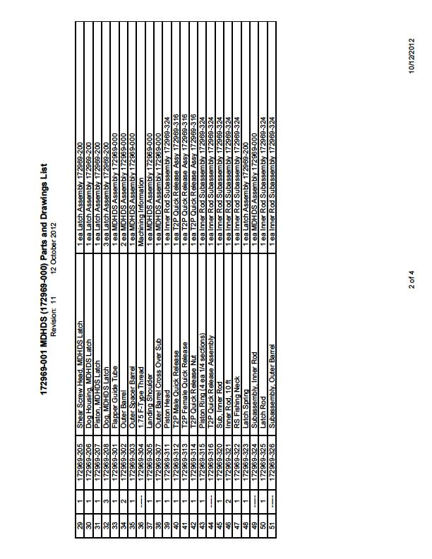
63 Appendix B MDHDS Parts List 63
64 64
65 65
66 66
67 67
68 Appendix C MDHDS Drawings (see electronic files) 68
69 Appendix D Drill String Pressure During MDHDS Unlatch Plot 69
70 The plot shows the pump strokes versus drill string pressure during unlocking of the MDHDS latch. Initially, the pump is brought on line and as the drill string pressure begins to increase sharply, the pump strokes are reduced. At this point in the unlocking process, the drill string pressure is increased to ~1,200 psi and held. The MDHDS does not completely blank off the drill string. Thus, some pumping may be required to maintain the drill string pressure for a dwell time of 1 min to 2 min. During this dwell period, the MDHDS shear screw head shears the shear screws and is pumped down relative to the latch. This action UNLOCKS the latch. However, the drill string pressure prevents the MDHDS piston from moving upward and unlatching the MDHDS inner rod subassembly. After the dwell period, the pump is shut off and the drill string pressure is bled off at the rig floor. Note, leave the rig floor bleed off valve open until ALL pressure is bled off and the stand pipe is drained. Once the drill string pressure has been bled off, the piston spring will push the piston up, unlatching the inner rod subassembly. When the pump is engaged once again, the inner rod assembly will be pumped out of the outer barrel subassembly and into the formation. 70
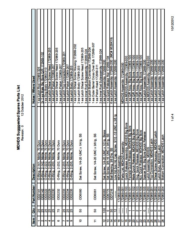
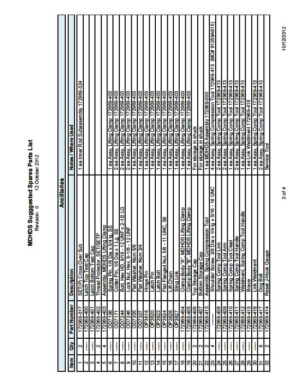
71 Appendix E MDHDS Suggested Spare Parts List The following parts list is of suggested spare parts to accompany the MDHDS for deployment at sea. It is also suggested that a minimum of two complete MDHDS assemblies be sent for deployment at sea. 71
72 72
73 73
74 74
75 75
76 76
MINING & DRILLING PRODUCTS. N2U Core Retrieval System
 MINING & DRILLING PRODUCTS NU Core Retrieval System CORE BARREL ASSEMBLY, NU -0-009 Core Barrel Assembly, 0 ft (.0 m)* -0-009 Core Barrel Assembly, ft (. m)* -0-009 Inner Tube Assembly, 0 ft (.0 m)* -0-009
MINING & DRILLING PRODUCTS. P Core Retrieval System
 MINING & DRILLING PRODUCTS P Core Retrieval System CORE BARREL ASSEMBLY, P -0-0 Core Barrel Assembly, 0 ft (.0 m) -0-0 Core Barrel Assembly, ft (. m) -0-0 Inner Tube Assembly, 0 ft (.0 m) -0-00 Inner Tube
MINING & DRILLING PRODUCTS. B Core Retrieval System
 MINING & DRILLING PRODUCTS B Core Retrieval System CORE BARREL ASSEMBLY, B -0-00 Core Barrel Assembly, 0 ft (.0 m) -0-00 Core Barrel Assembly, ft (. m) -0-00 Inner Tube Assembly, 0 ft (.0 m) -0-00 Inner
Full Flow Reverse Circulation Junk Baskets. Manual B320
 Full Flow Reverse Circulation Junk Baskets Manual B320 CONTENTS Logan Full Flow Reverse Circulation Junk Basket Overview... 2 Uses... 2 Construction... 2 Tool Illustration... 3 Operation... 4 Recovering
MINING & DRILLING PRODUCTS. N3 Core Retrieval System
 MINING & DRILLING PRODUCTS N Core Retrieval System CORE BARREL ASSEMBLY, N - - 090 Core Barrel Assembly, 0 ft (.0 m) - - 09 Core Barrel Assembly, ft (. m) - - 09 Inner Tube Assembly, 0 ft (.0 m) - - 09
Continuous Sampling OVERSHOT STYLE ROD STYLE SWIVEL OVERSHOT ASSEMBLY CONNECTING ROD NWJ J SERIES LATCH HOUSING LATCH ASSEMBLY BEARING ASSEMBLY
 ROD STYLE OVERSHOT STYLE OVERSHOT ASSEMBLY SWIVEL CONNECTING ROD NWJ J SERIES LATCH HOUSING LATCH ASSEMBLY BEARING ASSEMBLY SAMPLE BARREL SPLIT OR SOLID SHOE Split Barrel Sampler Assemblies Continuous
DRILLING MOTOR HANDBOOK
 DRILLING MOTOR HANDBOOK GORILLA Drilling Motors TM rev213.6.19 DRILLING MOTOR HANDBOOK www.axonep.com The information contained in this handbook is for reference only. AXON Downhole Products Inc. does
#10 Setting Tool Assembly Product Family No (10)
") BRICO Oil Tools provides a dependable line of Wireline Pressure Setting Tools for the Wireline industry worldwide. Our engineering, high quality and service provides a cost effective alternative. BT#10
BRICO Oil Tools provides a dependable line of Wireline Pressure Setting Tools for the Wireline industry worldwide. Our engineering, high quality and service provides a cost effective alternative. BT#10
Thru-Tubing. Motors and standard tools
 Thru-Tubing Motors and standard tools Thru-Tubing Reliable. Innovative. Premium. We are proud of our products and their contribution to the downhole drilling and thru-tubing industries. Research Innovate
Internal Pressure Pipe Cutters. Manual E540
 Internal Pressure Pipe Cutters Manual E540 Contents Logan Internal Pressure Pipe Cutters Overview...2 Uses...2 Construction...2 Tool Illustration...3 Operation...2 Single Cut from a Fixed Platform... 2
LEE NAK GUI TCP SERVICE COORDINATOR APPS
 Live Well Deployment System LEE NAK GUI TCP SERVICE COORDINATOR Challenges Monobore completion High angle wells Long perforation intervals Underbalanced perforating (static or dynamic) Well control barriers
Fishing Bumper Sub. Manual D450
 Fishing Bumper Sub Manual D450 Contents Fishing Bumper Sub Overview...2 Use...2 Construction...2 Illustration...3 Operation...4 Fishing Operations...4 Drilling Operations...4 Applying a Downward Blow...4
Casing Scraper. Service Equipment. Features
 Casing Scraper The Casing Scraper is a spring type, mechanical casing scraper, featuring a large by-pass area between the blades to allow circulation of debris. The body is constructed of the highest quality
Fast, Effective Blowout Protection
 Dual or Single Ram Hydraulic BOPs Fast, Effective Blowout Protection MODEL DRH - DUAL RAM HYDRAULIC BOP Guide Rib Pipe Centering Guide Ram Rubber Pipe Ram Block Door Cylinder Locking Shaft Lip-Type Piston
Overshots. Drill Rods. Casing. Tools 08/05-MKT1565 P/N L
 REV 0-NOV-05 Diamond Products Core Barrels Overshots Drill Rods Water Swivels Hoisting Plugs Casing Recovery Tools Adapter Subs Conversion Kits Tools Technical Data Safety Poster Diamond Products Impregnated
H Core Retrieval System
 H Core Retrieval System Global Drilling Products Pte Ltd 9 Loyang Way, #0-0, Changi Logistics Centre Singapore 0 Telephone: + 9 info@globaldrillingproducts.com www.globaldrillingproducts.com Core Barrel
STEERING COLUMN - TILT
 STEERING COLUMN - TILT 1993 Toyota Celica 1993 STEERING Toyota - Steering Columns - Tilt Wheel Celica DESCRIPTION & OPERATION Tilt steering wheels incorporate an upper steering shaft, attached by a "U"
Maintenance Information
 16573321 Edition 3 February 2014 Air Grinder Series 61H Maintenance Information Save These Instructions Product Safety Information WARNING Failure to observe the following warnings, and to avoid these
STEERING COLUMN - TILT
 STEERING COLUMN - TILT 1994 Toyota Celica 1994 STEERING Toyota - Steering Column - Tilt Wheel Celica DESCRIPTION & OPERATION Tilt steering wheels incorporate a mainshaft, attached by a "U" joint to an
Maintenance Information
 Form 16573321 Edition 1 July 2004 Air Grinder Series 61H Maintenance Information Save These Instructions Always wear eye protection when operating or performing maintenance on this tool. Always turn off
Drilling & Down-hole Completion Tools
 HYDRAULIC SET PRODUCTION PACKER MODEL: WC-HP-1 & WC-HPL-1[Large Bore] PRODUCT No.: WC-20101 & WC-20112 HP-1 is an industry standard, fully hydrostatic, hydraulic set and shear release single string retrievable
Hydraulic Release Overshots. Manual A115
 Hydraulic Release Overshots Manual A115 contents Logan Hydraulic Release Overshots Overview...2 Construction...2 Operation...2 Normal Straight Hole Well Application... 2 Directional Well Application...
Maintenance Information
 16572679 Edition 2 May 2014 Air Drill QP Series Maintenance Information Save These Instructions Product Safety Information WARNING Failure to observe the following warnings, and to avoid these potentially
Sachs shock manual. ( ) 2 & 4 Stroke RR Enduro. ( ) RS Dual Sport
 2 & 4 Stroke RR Enduro. ( ) RS Dual Sport") Sachs shock manual (2013 2015) 2 & 4 Stroke RR Enduro (2014-2015) RS Dual Sport 1 Introduction The procedures in this manual must take place in a clean environment using professional tools and some specific,
Sachs shock manual (2013 2015) 2 & 4 Stroke RR Enduro (2014-2015) RS Dual Sport 1 Introduction The procedures in this manual must take place in a clean environment using professional tools and some specific,
Nut The standard bottom nut is a bullnose nut. Optional nut types, sub, mill, and side hill, are available.
 Overview Logan Releasing Spears provide a positive means to engage and retrieve an internal fish from the well. The design of this rugged, dependable, and inexpensive internal catch fishing tool ensures
Completion Solutions Inc.
 Completion Solutions Inc. Simple Designs That Simply Work! Company Introduction Dec 2012 1 Who is Completions Solutions Inc? Founded in 2012 Focused on efficient and economical well bore stimulation (both
APPROACH OPERATING LLC. RIG: Latshaw rig #22 KB: 28
 MORNING DRILLING REPORT Date: 8/18/2013 Day: 1 Present Operation: waiting on daylight to finish rig move Depth: Footage: Rot. Hrs.: Cum Rot Hrs: 0 Daily ROP: ##### Brief Description Of Operations: move
SD Bendix DD-3 & SD-3 Safety Actuators PUSH PLATE & SHAFT ASSY. LOCKPORT SERVICE DIAPHRAGM SEPARATOR LOCKING PISTON O-RING LOCKING PISTON
 SD-02-4600 Bendix DD-3 & SD-3 Safety Actuators AUXILIARY DIAPHRAGM SERVICE DIAPHRAGM SEPARATOR PUSH PLATE & SHAFT ASSY. LOCKING PISTON O-RING LOCKING PISTON LOCKPORT DRAIN SLOT RETURN SPRING CAP O-RING
WLTC Retrievable Bridge Plug
 service Tools WLTC Retrievable Bridge Plug The WLTC Retrievable Bridge Plug is designed to perform all tasks normally required of a tubing run packer-type bridge plug and can be quickly converted to run
TOP DRIVE OPERATIONS & MAINTENANCE MANUAL JULY 2007 HYBRID TECHNOLOGY UNIVERSAL LIFTING CEMENT HEAD. Det Norske Vertis Type Certificate D-2928
 TOP DRIVE UNIVERSAL LIFTING CEMENT HEAD SUPER SUB SEA OPERATIONS & MAINTENANCE MANUAL JULY 2007 Det Norske Vertis Type Certificate D-2928 HYBRID TECHNOLOGY 1443 South Gage Street, San Bernardino, California
SERVICE TOOLS. Magnus MDT Service Packer V-III Un-Loader Valve MANC Storm Valve
 s ervice packers Magnus MDT Service Packer V-III Un-Loader Valve MANC Storm Valve Magnus MDT Service Packer Magnus MDT Retrievable Packer consists is a compression set packer with hydraulic hold down that
Drop-In Inside Blowout Preventer Valve
 Drop-In Inside Blowout Preventer Valve Disassembly and Assembly Procedures Global Manufacturing, Inc. Lafayette, Louisiana USA 70508 Ph (337) 237-1727 Fax (337) 232-9353 Disassembly and Assembly Procedures
Insta-Valve 250 Patriot TM
 Insta-Valve 250 Patriot TM 4-12 Nominal Size Installation Instructions for use with the Hydra-Core Pipewall Sampling Kit IV250MAN 4-12 IV 250 PWSK v1.93 Revised 07/11/2018 Covered by United States Patent
Installation and Maintenance Instructions JSE MAEAD Extruder Clutch. World Leader in Modular Torque Limiters
 World Leader in Modular Torque Limiters Installation and Maintenance Instructions JSE.5-0104MAEAD Extruder Clutch 1304 Twin Oaks Street Wichita Falls, Texas 76302 (940) 723-7800 Fax: (940) 723-7888 E-mail:
Models & & 4 Air Operated Bypass Pressure Control Valves SM64501
 SM64501 September 2008 Aerospace Group Conveyance Systems Division Carter Brand Ground Fueling Equipment Applicable addition manuals: None Maintenance & Repair Manual 3 & 4 Air Operated Bypass Pressure
Overshots. Drill Rods. Casing. Tools 08/05-MKT1565 P/N L
 REV 0-NOV-05 Diamond Products Core Barrels Overshots Drill Rods Water Swivels Hoisting Plugs Casing Recovery Tools Adapter Subs Conversion Kits Tools Technical Data Safety Poster Diamond Products Impregnated
GH-BETTIS OPERATING & MAINTENANCE INSTRUCTIONS DISASSEMBLY & ASSEMBLY FOR THE T80X-M4-S DOUBLE ACTING SERIES HYDRAULIC ACTUATORS
 GH-BETTIS OPERATING & MAINTENANCE INSTRUCTIONS DISASSEMBLY & ASSEMBLY FOR THE T80X-M4-S DOUBLE ACTING SERIES HYDRAULIC ACTUATORS -S INDICATES CYLINDERS ARE IN TANDEM PART NUMBER: 100121 REVISION "A" ECN
REMEMBER... SAFETY FIRST, EVERY TIME
 SIZE: 3.00 FEBRUARY 19, 2019 REV: 1.2 Page 1 of 10 REMEMBER... SAFETY FIRST, EVERY TIME Always use eye protection when using power tools. Always wear protective footwear when working in a workshop environment.
SECTION VI: BHP INSTRUMENT HANGERS ACCESSORIES
 INDEX of SECTION VI: BHP TOOLS PRUCT DESCRIPTION BHP TOOLS BHP - and TOOLS Product Code Page VI-0-16 A - For LANDING NIPPLES: VI-1-9 ROTFSB 33 1 ROTFWB 33 1 ROTRZB 33 2,3 ROH and RNH 33 4,5 XNH and XOH
COILED TUBING TOOLS SALE RENTAL - LEASE
 COILED TUBING TOOLS SALE RENTAL - LEASE GTECH Energy Services LLC 67 Pinepath Pl. Spring, Texas 77381 PH: 713-703-2959 Fax: 713-510-1802 sales@gtechenergyservices.com SALES@GTECHENERGYSERVICES.COM 1 PRODUCT
SECTION VIII: TEST TOOLS and CHECK VALVES
 INDEX of SECTION VIII: PRODUCT DESCRIPTION Code Page TEST TOOLS, VIII-0-10 ROTFB-2 12 1,2 ROTRB-2 12 3,4 ROTN 14 5,6 ROTR 14 7 ROTX 14 8 POR - PORN and POX - POXN 14 9 CVR - CVRN and CVX - CVXN Check Valve
RENTAL TOOL SERVICES. Megaton Impact Tools
 Megaton Impact Tools Upper Connector Megaton Impact Tools optimize your drilling operations. Drive Mandrel Female Spline Bearing Female Spline New-Generation Drilling Tools Megaton Drilling Jar Frees the
APPROACH OPERATING LLC. RIG: Latshaw rig # 22 KB: 28
 MORNING DRILLING REPORT Date: 6/5/2013 Day: 1 Present Operation: Drilling 12 1/4" hole with bit # 1 Depth: 609 Footage: 569 Rot. Hrs.: 6 Cum Rot Hrs: 6 Daily ROP: 94.83 Brief Description Of Operations:
Installation, Operation, and Maintenance Manual
 Installation, Operation, and Maintenance Manual Welker Automatic Insertion Heated Regulator High Voltage Model IHRA-4SS-220/230 100 or more inch insertion length The information in this manual has been
PARTS ORDERING INFORMATION
 RP-268 REPAIR PARTS FOR VE268 Roll Grooving Tool PARTS ORDERING INFORMATION When ordering parts the following information is necessary for the Victaulic Tool Company to promptly process the order and send
Dynamic MDT Service Packer V-III Un-Loader Valve ANC Storm Valve
 Dynamic MDT Service Packer V-III Un-Loader Valve ANC Storm Valve Dynamic MDT Service Packer Dynamic MDT Retrievable Packer consists of a compression set packer with hydraulic hold down that is designed
INSTALLATION GUIDE. Kawasaki KLR Manual Revision:
 REKLUSE MOTOR SPORTS The z-start Pro Clutch INSTALLATION GUIDE Kawasaki KLR650 191-640 Manual Revision: 030308 2007 Rekluse Motor Sports Rekluse Motor Sports, Inc. 110 E. 43rd Street Boise, Idaho 83714
DISASSEMBLY & REASSEMBLY INSTRUCTIONS
 DISASSEMBLY & REASSEMBLY INSTRUCTIONS FOR SINGLE ACTING TELESCOPIC CYLINDERS MUNCIE POWER PRODUCTS, INC. Telescopic Cylinder Disassembly & Reassembly Instructions TABLE OF CONTENTS Warning & Safety Recommendations...
W I L D W E L L C O N T R O L WIRELINE OPERATIONS
 WIRELINE OPERATIONS Wireline Operations Learning Objectives You will learn various activities suitable for wireline operations. You will learn best practices and techniques for conducting wireline operations.
INSTALLATION GUIDE. Clutch Cable Actuated Models Manual Revision:
 REKLUSE MOTOR SPORTS The z-start Pro Clutch INSTALLATION GUIDE Clutch Cable Actuated Models 191-800 Manual Revision: 061810 2002 Rekluse Motor Sports Rekluse Motor Sports, Inc. 110 E. 43rd Street Boise,
SD Bendix E-10PR Retarder Control Brake Valve DESCRIPTION. OPERATION - Refer to Figure 2
 SD-03-832 Bendix E-10PR Retarder Control Brake Valve MOUNTING PLATE SUPPLY 4 PORTS ELECTRICAL AUXILIARY DESCRIPTION TREADLE RETARDER CONTROL SECTION EXHAUST DELIVERY 4 PORTS FIGURE 1 - E-10PR RETARDER
NEECO INDUSTRIES INC. INSTRUCTION MANUAL 7 1/16 10K SLAB GATE BODY
 INSTRUCTION MANUAL 7 1/16 10K SLAB GATE BODY INTRODUCTION The NF-700 type gate valves provided by Neeco Industries are full-bore through conduit non-rising stem manually (w/ball screw) operated valves.
OPERATION AND PARTS MANUAL
 OPERATION AND PARTS MANUAL MODEL NUMBER : PART NUMBER : GTL 1110 1900-0510 SERIAL NUMBER : BAYNE MACHINE WORKS, INC. PHONE: (864) 288-3877 910 FORK SHOALS ROAD TOLL FREE: (800) 535-2671 GREENVILLE S.C.,
3.2 DRIVE TORQUE HUB. Roll, Leak and Brake Testing SECTION 3 - CHASSIS & TURNTABLE. 3-2 JLG Lift
 3.2 DRIVE TORQUE HUB Roll, Leak and Brake Testing 10 LUG PATTERN Torque-Hub units should always be roll and leak tested before disassembly and after assembly to make sure that the unit's gears, bearings
HYDRAULICS. TX420 & & lower. Hydraulic Tandem Pump Removal. 4. Remove the LH side panel (Fig. 0388).
.") TX420 & 425 240000299 & lower 4. Remove the LH side panel (Fig. 0388). Hydraulic Tandem Pump Removal Note: Cleanliness is a key factor in a successful repair of any hydraulic system. Thoroughly clean all
TX420 & 425 240000299 & lower 4. Remove the LH side panel (Fig. 0388). Hydraulic Tandem Pump Removal Note: Cleanliness is a key factor in a successful repair of any hydraulic system. Thoroughly clean all
INSTALLATION GUIDE. KTM 125, 144, Stroke KTM 250, Stroke KTM 250 SXF, XC, XC-W KTM 450, 505 SXF Manual Revision:
 REKLUSE MOTOR SPORTS The z-start Pro Clutch INSTALLATION GUIDE KTM 125, 144, 200 2-Stroke KTM 250, 300 2-Stroke KTM 250 SXF, XC, XC-W KTM 450, 505 SXF 191-836 Manual Revision: 050307 2002 Rekluse Motor
CONTENTS. Product Features and Specifications Installation Requirement Installation Exploded View Operation Instruction...
 1 CONTENTS Product Features and Specifications... 3 Installation Requirement... 5 Installation... 6 Exploded View... 20 Test... 22 Operation Instruction... 25 Maintenance... 26 Trouble Shooting... 27 Parts
OPERATION AND PARTS MANUAL
 OPERATION AND PARTS MANUAL MODEL NUMBER : PART NUMBER : GRL 1110 1900-0540 SERIAL NUMBER : BAYNE MACHINE WORKS, INC. PHONE: 864.288.3877 910 FORK SHOALS ROAD TOLL FREE: 800.535.2671 GREENVILLE SC, 29605
FPU SYSTEMS OPERATION MANUAL (INCLUDING REPAIR PARTS & SPECIAL TOOL LIST) BOH CONTAINERIZED MISSION SYSTEMS CCC and EWCC BOH FPU Field Pack-up Units
 BOH CONTAINERIZED MISSION SYSTEMS CCC and EWCC BOH FPU Field Pack-up Units") FPU SYSTEMS OPERATION MANUAL (INCLUDING REPAIR PARTS & SPECIAL TOOL LIST) BOH CONTAINERIZED MISSION SYSTEMS CCC and EWCC BOH FPU Field Pack-up Units CHAPTER 2 OPERATOR INSTRUCTIONS 2016 BOH Environmental
FPU SYSTEMS OPERATION MANUAL (INCLUDING REPAIR PARTS & SPECIAL TOOL LIST) BOH CONTAINERIZED MISSION SYSTEMS CCC and EWCC BOH FPU Field Pack-up Units CHAPTER 2 OPERATOR INSTRUCTIONS 2016 BOH Environmental
AF0465-XX SERVICE KITS GENERAL DESCRIPTION MODEL DESCRIPTION CHART OPERATING AND SAFETY PRECAUTIONS THIS MANUAL COVERS THE FOLLOWING MODELS
 OPERATOR S MANUAL INCLUDING: SERVICE KITS, TROUBLESHOOTING, PARTS LIST, DISASSEMBLY & REASSEMBLY. 4-1/4 AIR MOTORS AF044X-XX (4 STROKE) and AF046X-XX (6 STROKE) Also covers 637489 service kits AF044X-XX
INSTRUCTION MANUAL 16K - Fifth Wheel Hitch
 You can take it with you. INSTRUCTION MANUAL 16K - Fifth Wheel Hitch Product No. 30047 DEALER/INSTALLER: END USER: (1) Provide this Manual to end user. (2) Physically demonstrate hitching and unhitching
Brake System H TX, H2.0TXS [B475]; H TX [B466] Safety Precautions Maintenance and Repair
![Brake System H TX, H2.0TXS [B475]; H TX [B466] Safety Precautions Maintenance and Repair](/thumbs/86/93834005.jpg "Brake System H TX, H2.0TXS [B475]; H TX [B466] Safety Precautions Maintenance and Repair") HMM180001 Brake System H1.5-1.8TX, H2.0TXS [B475]; H2.5-3.5TX [B466] Safety Precautions Maintenance and Repair When lifting parts or assemblies, make sure all slings, chains, or cables are correctly fastened,
HMM180001 Brake System H1.5-1.8TX, H2.0TXS [B475]; H2.5-3.5TX [B466] Safety Precautions Maintenance and Repair When lifting parts or assemblies, make sure all slings, chains, or cables are correctly fastened,
Overshots. Drill Rods. Casing. Tools 12/06-MKT1644 P/N M
 REV 0-DEC-06 Diamond Products Core Barrels Overshots Drill Rods Water Swivels Hoisting Plugs Casing Recovery Tools Adapter Subs Conversion Kits Tools Technical Data Diamond Products Impregnated Bits Reaming
Fisher 657 Diaphragm Actuator Sizes and 87
 Instruction Manual 657 Actuator (30-70 and 87) Fisher 657 Diaphragm Actuator Sizes 30 70 and 87 Contents Introduction... 1 Scope of Manual... 1 Description... 2 Specifications... 2 Installation... 3 Mounting
Installation, Operation & Maintenance Manual for Flo-Max II Coupler Model FM126
 IMPORTANT: The Flo-Max II coupler is designed to disconnect the nurse tank hose from a tool bar before the straight pull force on the hose exceeds 450 pounds. Upon disconnect, swing checks in both halves
Maintenance Information
 45528270 Edition 1 June 2007 Barring Motor T480 Series Maintenance Information Save These Instructions WARNING Always wear eye protection when operating or performing maintenance on this Barring Motor.
Partner - Drilling. Well Name: Fcu State/Province Texas Ground/Corrected Ground Elevation (ft) Rig
 Rig") : 4/8/2016 Release Wait on daylight to complete rig move. 95,193.70 95,193.70 24hr MIRU from FCU 7220 to FCU 7442. Change out gen #2 motor. Clean and service rig. Wait on daylight to complete rig move.
: 4/8/2016 Release Wait on daylight to complete rig move. 95,193.70 95,193.70 24hr MIRU from FCU 7220 to FCU 7442. Change out gen #2 motor. Clean and service rig. Wait on daylight to complete rig move.
Hydraulic Wireline Jar. Manual D460
 Hydraulic Wireline Jar Manual D460 Contents Logan Hydraulic Wireline Jar Overview... 2 Uses... 2 Construction... 2 Operation... 2 Tool Illustration... 3 Maintenance... 4 Disassembly... 4 Assembly... 4
Installation and Maintenance Instructions JSE2-0241MAEAD Extruder Clutch. World Leader in Modular Torque Limiters
 World Leader in Modular Torque Limiters Installation and Maintenance Instructions JSE2-0241MAEAD Extruder Clutch 1304 Twin Oaks Street Wichita Falls, Texas 76302 (940) 723-7800 Fax: (940) 723-7888 E-mail:
6200 Series. Specifications. Fluid End Power End Models 6211, 6212, 6221, & 6222 Models 6241 & 6242 Part Material Part Material Part Material
 5.2018.12.i 6200 Series Specifications The Flomore 6200 Series Pump line consists of a series of basic pump options all developed from a modular power unit. All units are pneumatically driven positive
EP1306N 5 Gallon Can Extruder System Rev. A June EP1306N Operation Manual
 EP1306N Operation Manual 1 THIS PAGE HAS BEEN INTENTIONALLY LEFT BLANK 2 TABLE OF CONTENTS SECTION 1: SAFETY... 4 1. GENERAL SAFETY... 5 2. PUMP SAFETY... 5 3. FLUID PRESSURE AND COMPATIBILITY... 6 4.
Sub Section Title Page No.
 Sub Section Title Page No. 1 Introduction 3 2 Routine Maintenance 3 3 Disassembly 4 3.1 Disassembly of Double Crank Design 4 3.2 Disassembly of Scotch Yoke Design 5 3.3 Disassembly of Actuator Cylinder
MWD Components Ceramic & Carbide Parts MWD Electronics Running Gear Handling Equipment Drill Pipe Screens Float Valves Repair Kits Job Boxes Gamma
 Float Valves Repair Kits Excellence in Energy Services for over years www.huntingplc.com Drilling drilling.tools@hunting-intl.com specialty.supply@hunting-intl.com www.hunting-intl.com/titan/contact-titan
Bettis M11 Manual Hydraulic Override System Operating Instructions for HD, T, and G Series Pneumatic and Hydraulic Actuators
 Instruction Manual D102755X012 March 2010 Bettis M11 Bettis M11 Manual Hydraulic Override System Operating Instructions for HD, T, and G Series Pneumatic and Hydraulic Actuators The following instruction
3 Inch & 4 Inch Digital Bypass Pressure Control Valves
 SM64505 September 2008 Aerospace Group Conveyance Systems Division Carter Brand Ground Fueling Applicable addition manuals: None Maintenance & Repair Manual 3 Inch & 4 Inch Digital Bypass Pressure Control
MAR031615A 1. PABD Installation & Maintenance. Guide *Parts will differ for high pressure valves.
 MAR031615A 1 PABD Installation & Maintenance Guide *Parts will differ for high pressure valves. Load Piston U-cup - Piston - U-cup Piston 1. Carefully place the u-cup over the neck of the piston. Load
INSTALLATION GUIDE CRF150R Manual Revision:
 REKLUSE MOTOR SPORTS The z-start Pro Clutch INSTALLATION GUIDE CRF150R 191-810 Manual Revision: 032508 2002 Rekluse Motor Sports Rekluse Motor Sports, Inc. 110 E. 43rd Street Boise, Idaho 83714 208-426-0659
Boston Gear LOR Series
 Boston Gear LOR Series Trig-O-Matic Lite Overload Release Clutch Installation and Maintenance Instructions Doc. No. LOR Series Trig-O-Matic Lite www.bostongear.com LOR SERIES TRIG-O-MATIC LITE OVERLOAD
Installation and Maintenance Instructions JSE1-0128MAEAD Extruder Clutch. World Leader in Modular Torque Limiters
 World Leader in Modular Torque Limiters Installation and Maintenance Instructions JSE1-0128MAEAD Extruder Clutch 1304 Twin Oaks Street Wichita Falls, Texas 76302 (940) 723-7800 Fax: (940) 723-7888 E-mail:
SERVICE PROCEDURES FOR CLUTCH HYDRAULIC UNITS
 SERVICE PROCEDURES FOR CLUTCH HYDRAULIC UNITS SAFETY PROCEDURES Always follow the vehicle manufacturer's recommended safety procedures in your Shop and Owners Manual. REQUIRED TOOLS Flat blade screwdriver,
MANUFACTURING. PD Impact Tools
 PD Impact Tools Upper Connector MANUFACTURING Drive Mandrel Female Spline Bearing Female Spline PD Impact Tools optimize your drilling operations. Knocker Housing Knocker Pressure Piston Hydraulic Mandrel
INSTALLATION INSTRUCTIONS
 INSTALLATION INSTRUCTIONS --1075 North Ave. Sanger, CA 93657-3539 local: 559-875-0222 fax: 559-876-2259 toll free: 800-445-3767-- 2505 Lowering Spindle Assembly Installation Instructions ½ TON SILVERADO
Benoit Premium Threading, LLC Recommended Practice. Approved By: Benoit Quality Assurance Department Date: January 6, 2017
 1 of 12 SCOPE The following outlines the recommended practices for field handling, running, and pulling of tubular products with Benoit Flush & and is intended to assist the user in the proper installation
EQUALIZER International Limited 10T(I) Integral Hydraulic Spreading Wedge Repair Instruction Manual
 Integral Hydraulic Spreading Wedge Repair Instruction Manual") EQUALIZER International Limited 10T(I) Integral Hydraulic Spreading Wedge Repair Instruction Manual INDEX THE EQUALIZER 10T(I) Integral Hydraulic Wedge SECTION CONTENTS PAGE NO (S) 03 04 05 06 07 08 09
EQUALIZER International Limited 10T(I) Integral Hydraulic Spreading Wedge Repair Instruction Manual INDEX THE EQUALIZER 10T(I) Integral Hydraulic Wedge SECTION CONTENTS PAGE NO (S) 03 04 05 06 07 08 09
Actuators & Surface Safety Valves
 Global Energy Market Solutions HYDRAULIC / PNEUMATIC Actuators & Surface Safety Valves Including: Accessories & Alternative Configurations 2017 Omni Valve Company, LLC, BRO-ACT Rev: 1.2 ENGINEERED FOR
T-2 On-Off Tool. Available with all common wireline profiles, the stinger works with industrystandard blanking plugs, standing valves and regulators.
 T-2 On-Off Tool Classic Oilfield s T-2 On-Off Tool enables the tubing string to be disconnected above a packer for zonal isolation, tubing retrieval, and temporary zone abandonment. The tool contains an
The Well Commander Mitigate drilling hazards with the industry s most versatile drilling valve. Todd Gooding Business Development Manager
 The Well Commander Mitigate drilling hazards with the industry s most versatile drilling valve Todd Gooding Business Development Manager WELL COMMANDER A COMPLETE redesign of the ball-activated Centurion
Overshots. Drill Rods. Casing. Tools 08/05-MKT1565 P/N L
 REV 0-NOV-05 Diamond Products Core Barrels Overshots Drill Rods Water Swivels Hoisting Plugs Casing Recovery Tools Adapter Subs Conversion Kits Tools Technical Data Safety Poster Diamond Products Impregnated
1989 Jeep Cherokee. STEERING COLUMN' '1989 STEERING Jeep Steering Columns STEERING COLUMN STEERING Jeep Steering Columns
 STEERING COLUMN 1989 STEERING Jeep Steering Columns DESCRIPTION All models use collapsible steering columns. All columns have integral ignition switch and locking device. Optional tilt wheel is available
Models & Inch & 4 Inch Digital Inline Pressure Control Valves SM64504
 SM64504 September 2008 Aerospace Group Conveyance Systems Division Carter Brand Ground Fueling Equipment Applicable addition manuals: None Maintenance & Repair Manual 3 Inch & 4 Inch Digital Inline Pressure
[ ]
![[ ]](/thumbs/77/75202648.jpg "[ ]") [ www.pigpopper.com ] Installation Guide Pig Popper Installation Guide Enduro Pipeline Services, Inc. P.O. Box 489 Tulsa, OK 740 500 S. 45th W. Ave. Tulsa, OK 7407 p: (98) 446-94 toll-free: (800) 75-68
[ www.pigpopper.com ] Installation Guide Pig Popper Installation Guide Enduro Pipeline Services, Inc. P.O. Box 489 Tulsa, OK 740 500 S. 45th W. Ave. Tulsa, OK 7407 p: (98) 446-94 toll-free: (800) 75-68
FOX Racing Shox Bypass Technical Manual.
 FOX Racing Shox Bypass Technical Manual. The following technical manual will be using a 2.5 dia. shock with three tubes for descriptions and illustrations. Your shock may differ in the number of tubes,
Service Tools Catalog
 Service Tools Catalog www.teamoiltools.com 2012 TEAM Oil Tools. All rights reserved. www.teamoiltools.com 2012 TEAM Oil Tools. All rights reserved. TABLE OF CONTENTS P/N Product Description Page Type P
TCI E4OD/4R100 Valve Body Performance Improver Kit
 151 INDUSTRIAL DRIVE ASHLAND, MISSISSIPPI 38603 http://www.tciauto.com TCI 496500 E4OD/4R100 Valve Body Performance Improver Kit TELEPHONE: 662-224-8972 FAX LINE: 662-224-8255 E-MAIL: tech@tciauto.com
ADDRESSABLE DISCONNECT TOOL MODEL DE MANUAL
 Pg. 1 of 77 ADDRESSABLE DISCONNECT TOOL MODEL DE MANUAL REVISION HISTORY AUTHOR REVISED SECTION/PARAGRAPH REV RELEASED Gary Floyd Final Draft 0 03/31/17 Draft and Archived/Obsolete revisions are not to
INSTRUCTION MANUAL. with ILLUSTRATED PARTS LIST. for TRAILER AND ACCESSORIES. Part Number (10,000 Pound Capacity)
") TO-37 0079 0884 07586 INSTRUCTION MANUAL with ILLUSTRATED PARTS LIST for TRAILER AND ACCESSORIES Part Number 48388- (0,000 Pound Capacity) manufactured by HOBART BROTHERS COMPANY POWER SYSTEMS DIVISION
TO-37 0079 0884 07586 INSTRUCTION MANUAL with ILLUSTRATED PARTS LIST for TRAILER AND ACCESSORIES Part Number 48388- (0,000 Pound Capacity) manufactured by HOBART BROTHERS COMPANY POWER SYSTEMS DIVISION
Gelcoat Fluid Section
 3102-00-01 Fluid Section MAGNUM VENUS PRODUCTS Maintenance & Repair Manual Part No. M3102-00-01 Revision 05.30.01 Maintenance & Repair Manual Fluid Section Module MVP Venus Phone: (253) 854-2660 (800)
Revision
 Revision - 2.0-04-26-2017 www.mcscontrols.com CONTENTS I. HOW TO REPLACE CAPACITY SOLENOID VALVE... 1 I-1. DISMANTLE SOLENOID VALVE... 1 I-2. ASSEMBLE SOLENOID VALVE... 2 II. HOW TO CHANGE 4-STEP TO STEP-LESS
Nonexplosiveoilfield Products Global Sales & Service
 Run-In & Plug Setting Procedures Document # DRI-9100-0000 1. Always test stroke the before attaching the bridge plug and before RIH. Always Soft-Start s A shooting panel cannot be used when powering a.
CALIFORNIA TRIMMER MOWER MAINTENANCE MANUAL
 CALIFORNIA TRIMMER MOWER MAINTENANCE MANUAL 2 Table of Contents Section 1: General Information Page Handle Assembly Instructions 4 Maintenance All Models 6 Oil Change Procedures All Models 9 Height Adjustment