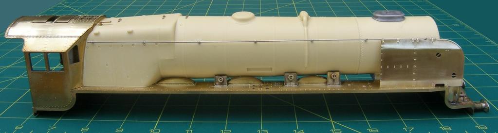
Finney7 PC May17 PRINCESS CORONATION. Fig 1. GA Curved Footplate
|
|
|
- Dayna McCarthy
- 5 years ago
- Views:
Transcription
1 Fig 1. GA Curved Footplate PC - 5
2 Fig 2. GA Utility Footplate PC - 6
3 COUPLING RODS & FRAME ASSEMBLY COUPLING RODS. The coupling rods are now made so that they can be used as a jig to align the remaining hornblocks accurately. First drill out all the crankpin holes to a convenient size which is undersize for the crankpins and the fork joint holes. Remove all burrs caused by the drilling. Now drill a hole, with the drill used for the crankpin holes, in a small block of wood or Tufnol and leave the drill in the wood with its shank projecting. This projecting shank is used as a mandrel to accurately align the laminations of each rod. Place the laminates over the mandrel and, using plenty of solder and flux, solder the two laminates together. You will now have rods with the crankpin and fork joint holes aligned. Carefully file the edges so that the 'laminated' effect is lost and the rods appear to be made from one piece of metal. The crankpin holes now need carefully opening out until they just fit, with no free play, the ends of the hornblock alignment jigs. The fork joints are now pinned using the 1.6 mm nickel silver wire. Retain the pins, which should be a tight fit, by lightly soldering on the inner face of the rods. The correctly assembled rods should now have a completely flush inner face. FRAMES ASSEMBLY Having decided which chassis to construct you can now start construction by preparing the frames (F1 & F2). Remove the etched cusp from the edges, open up all holes to the required size and emboss all the rivets (except for the hole and two rivets in a vertical line on the right side rear frame for some engines - see Fig 1). Open up to 0.9 mm the holes for the sand pipes in the sandbox bases and fold out as shown in Fig 4. Form the bends in the rear outside frames over a ¼ rod. Clean up the edges of the rear inside frames (F5 & F6) and bend to shape. To construct the kit as designed with a compensated chassis open out the frame slots for the hornblocks by cutting up the half etched lines. Assemble the hornblocks and solder one of the front hornblocks to the inside of the frame aligning it with the half etched line. Select the stretchers for your chosen gauge O Fine or Scaleseven. Remove the following stretchers - rear truck pivot (F11 or F12), brake cylinder (F13 or F14) and front compensation beam (F17 or F18). Open out the holes for the front compensation beam in part F17/F18 to 1/16". Fold up the stretchers making sure the 1/2 etched fold line is on the inside and that each bend is a right angle. Check that all the tabs on the stretchers fit properly in their corresponding chassis slots so that the rest of the stay is hard up against the inside of the frames. Tap 10BA the motion bracket fixing holes in F17/F18. Solder an 8BA nut over the hole in F11/F12, for the rear truck pivot. Solder the brake shaft bracket (F15) in place in the slots in F13/F14. Now assemble the frames and stretchers. Start by tack soldering F17/F18 to both frames. Check that everything is square and that the stays are hard against the frames. Put an axle (or better a longer piece of 3/16" rod) through the front bearings, together with the second hornblock and spring as shown in the hornblock instructions. Place the chassis on a piece of graph paper to check that the axle is square to the frames. If all is well solder the second hornblock to the frame and the remaining stretchers to the frames checking constantly that the chassis is square and the frames are straight. Open up all the holes in the rear stretcher (F7) before making all the bends. Add the loco/tender hose connection spigots from 0.8 mm and 1.2 mm wire. See page PC-15. Tack solder the rear truck rubbing plate (F8) in the slots in the inside rear frames. Now assemble the inside rear frames together with parts F7, F8 & the fillet between the rear frames (F9). Make the bends in the firebox base (D1) and clip it in place over the tabs on the top edges of the inside rear frames to ensure their correct spacing. Place the assembly over Fig 4 to check for errors before making all the soldered joints. Do not solder part D1 in place yet. COMPENSATION The front beam is a piece of 1/16" steel wire through the holes in F17/F18 with a piece of 3/32 tube added as shown below. For the rear beams cut a piece of 1/8" brass rod so that it fits through the holes in the frames and is flush with their outside face. Cut two equal pieces 5/32" tube which together fit between the frames and solder the rear beams (F16) to the 5/32 tubes 1 mm from one end. Temporarily fit the beams. Temporarily fit all the wheels and axles and confirm that the compensation works properly and check that the chassis is sitting level. The height of the top of the frames above rail level, between the coupled wheels, should be 45.8 mm. FRAME OVERLAYS For Scaleseven remove the front section of the frame overlays (F3 & F4) as shown in Fig 4. If you are not fitting the BR Smith- Stone speedometer remove the mounting bracket that folds down from the left side frame bracket and reshape the lower edge of the bracket so that it matches the right side bracket. Emboss all the rivets before folding up the frame brackets. These brackets will need shortening for Scaleseven to compensate for the wider frame spacing. Solder in place lengths of 0.8 mm wire for the brake hanger pivots. These then serve to accurately locate the overlays which then only need tack soldering around their edges. D1 Firebox base 4 F1 Frame, left 6 F2 Frame, right 6 F3 Frame overlay, left 3 F4 Frame overlay, right 3 F5 Rear inside frame, left 6 F6 Rear inside frame, right 6 F7 Stretcher, rear 7 F8 Rear truck rubbing plate (2) 3 F9 Fillet between rear frames (2) 2 F10 Washer - injector exhaust pipe (2) 1 F11 Stretcher, rear truck pivot OF 7 F12 Stretcher, rear truck pivot S7 7 F16 Compensation beam (2) 7 F17 Stretcher, front compensation beam OF 7 F18 Stretcher, front compensation beam S7 6 M12 Coupling rod rear inner lamination (2) 8 M13 Coupling rod rear outer lamination (2) 8 M14 Coupling rod front inner lamination (2) 8 M15 Coupling rod front outer lamination (2) 8 Remove shaded area from overlays for S7 chassis 3/32 tube 1/16 steel wire pivot F16 1/8 wire pivot, 5/32 tube Section on XX 8BA nut D1 Fig 3. Coupling Rods F24 here for finescale locomotive F17 or F18 F3 F13 or F14 F15 F11 or F12 F9 0.7 mm P/B wire F8 F7 F1 F5 X F9 F8 X F2 F6 Tap 10BA F4 0.8 mm wire brake pivots BR25 here Blue holes for 0.8 mm wire frame pins Fig 4. Initial Frame Assembly Red holes for 0.8 mm wire brake pivots PC - 7
4 UTILITY FRONT END Remove the etched cusp from the edges, open up all holes to the required size and emboss all the rivets on front frames, left and right (F35 & F36). Tap 10BA the motion bracket fixing holes in the cylinder mounting brackets and rocking arm pivot brackets. Fold out the cylinder mounting and rocking arm pivot brackets. Open up the holes in the valve rocking lever pivot upper bracket (F37) to 1.7 mm to clear the 10BA screw. Cut two pieces of 3/32 tube 3.4 mm long. Fit part F37 in place together with the tube and screw and solder to the frames on the inside. Ensure that the tube and screw are removable. Fit valve rocking lever pivot bracket overlay (F38). Solder a 6BA nut and a 6 mm long length of 2 mm wire in place on the stretcher for bogie mounting (F41). Emboss the rivets on inside cylinder stretcher (F42) and fold up. Fold up the front steps, lower and upper (F45 & F46) and solder in place in the recesses in the front step assembly (F44) before folding the step assembly up. Emboss the rivets on the front buffer beam (U15), the utility front footplate (U21) and the utility front footplate inside cylinder cover (U25). The rivets to emboss in the bufferbeam are shown in Fig 5. Fold up the rear edge of the footplate, solder the bufferbeam to the footplate and then add the buffer beams and frame webs (F43). Next add the utility side valance (U24). Form the inside cylinder cover (U25) to shape checking that it fits in the recesses in the frames. Form the inside cylinder cover overlay (U26) so that it fits over inside cylinder cover and the holes for inside cylinder valve tail rod cover (BR34) align. Solder the cover and overlay together. Detail the hinges on the access hatch with 0.4 mm copper wire. Attach the lifting hole strengthening plates (F48) to the inside of the frames. Open up all the holes in the outside cylinders (M1), emboss the rivets and fold the bends including the bracket which supports the valve rod. Assemble the frames and stretchers, and the inside cylinder cover, front footplate and step assembly, by screwing the cylinders in place. Check that the assembly fits together with the main frames with two lengths of 0.8 mm wire through the holes in red shown in Fig 5, pinning them together. For Finescale, the packing piece between the frames and the front frames (F24) fits between the frames - outside the main frames and inside the front frames (See Fig. 4). It is very important that the joining pins are a tight fit in the frame holes so that the alignment is accurate. If all is well, then solder the two stretchers, the bogie mounting and inside cylinders (F41 & F42) in place. Do not solder the front frames to the main frames yet (See P-12). Solder the step assembly to the front frames, then add the front footplate and then the inside cylinder cover. Form the slight bend in the cylinder flange plate webs (F40) and solder in place in the slot in the cylinder flange plate (F39). Now solder the flange plate and web to the frames against the front face of the cylinders taking care not to solder them to the cylinders. The rest of the detail shown in Fig 5, except the angle on the footplate below the smokebox door (U28), can now be added to the front frames although you may prefer to leave this until later. F24 Packing between frames and front frames (2) 3 F35 Front frame left 6 F36 Front frame right 6 F37 Valve rocking lever pivot upper bracket (2) 7 F38 Valve rocking lever pivot bracket overlay (2) 7 F39 Cylinder flange plate (2) 7 F40 Cylinder flange plate web (2) 1 F41 Stretcher bogie mounting 7 F42 Stretcher inside cylinders 7 F43 Bufferbeam and frame webs (2) 3 F44 Front step assembly 4 F45 Front step, lower (2) 4 F46 Front step, upper (2) 4 F48 Lifting hole strengthening plate (2) 1 F49 Bogie wheel splasher frame overlay 2 F50 Bogie splasher top 2 F51 Bogie splasher front 2 F52 Bracket, frame to footplate (2) 5 F47 Front step stay (2) 4 M1 Outside cylinders 7 U15 Front bufferbeam 4 U21 Utility front footplate 5 U22 Utility front footplate, frame support bracket 5 U23 Utility front footplate, small step 1 U24 Utility front footplate, side valence (2) 5 U25 Utility front footplate, inside cylinder cover 4 U26 Utility front footplate, inside cylinder cover overlay 5 U27 Utility front footplate - angle between cylinder cover and footplate 3 U28 Angle on footplate beneath smokebox door 3 U25 F37 U21 U15 Section on XX 3/32 tube F52 F48 U26 U25 U23 F44 F52 F42 BR29 F39 F40 F41 2 mm wire 2.9mm Dia 2.4mm Dia M1 F37 U22 F38 3.6mm Dia 1.2mm Dia F44 F49 F46 F45 F47 U15 F43 U24 BR8 BR6 Mountings - tap 10BA F51 Rocking arm pivot - tap 10BA 1.4mm Dia 3.6mm Dia 1.2mm Dia F43 F44 X U27 U21 F48 F50 F36 X F35 Fig 6. Outside Cylinder Folds F52 F40 Fig 5. Utility Front Frames PC - 8
5 CURVED FRONT END Remove the etched cusp from the edges, open up all holes to the required size and emboss all the rivets on front frames, left and right (F35 & F36). For locomotives with a curved front plate modify the front profile of frames to that shown in Fig 8. Tap 10BA the motion bracket fixing holes in the cylinder mounting brackets and rocking arm pivot brackets. Fold out the cylinder mounting and rocking arm pivot brackets. Open up the holes in the valve rocking lever pivot upper bracket (F37) to 1.7 mm to clear the 10BA screw. Cut two pieces of 3/32 tube 3.4 mm long. Fit part F37 in place together with the tube and screw and solder to the frames on the inside. Ensure that the tube and screw are removable. Fit valve rocking lever pivot bracket overlay (F38). Solder a 6BA nut and a 6 mm long length of 2 mm wire in place on the stretcher for bogie mounting (F41). Emboss the rivets on inside cylinder stretcher (F42) and fold up. Fold up the front steps, lower and upper (F45 & F46) and solder in place in the recesses in the front step assembly (F44) before folding the step assembly up. Open up all the holes in the outside cylinders (M1), emboss the rivets and fold the bends including the bracket which supports the valve rod. Assemble the frames, stretchers and step assembly, by screwing the cylinders in place. Check that the assembly fits together with the main frames with two lengths of 0.8 mm wire through the holes shown in red on Fig 8 pinning them together. For Finescale part F24 fits between the frames; outside the main frames and inside the front frames (See Fig. 4). It is very important that the joining pins are a tight fit in the frame holes so that the alignment is accurate. If all is well then solder the stretchers in place. Do not solder the front frames to the main frames yet (See P-12). Form the slight bend in the cylinder flange plate webs (F40) and solder in place in the slot in the cylinder flange plate (F39). Now solder the flange plate and web to the frames against the front face of the cylinders taking care not to solder them to the cylinders. The rest of the detail shown in Fig 8 can now be added to the front frames although you may prefer to leave this until later. F35 Front frame left 6 F36 Front frame right 6 F37 Valve rocking lever pivot upper bracket (2) 7 F38 Valve rocking lever pivot bracket overlay (2) 7 F39 Cylinder flange plate (2) 7 F40 Cylinder flange plate web (2) 1 F41 Stretcher bogie mounting 7 F42 Stretcher inside cylinders 7 F43 Bufferbeam/frame webs (2) 3 F44 Front step assembly 4 F45 Front step, lower (2) 4 F46 Front step, upper (2) 4 F49 Bogie wheel splasher frame overlay 2 F50 Bogie wheel splasher top 2 F51 Bogie wheel splasher front 2 F52 Bracket, frame to footplate (2) 5 F47 Front step stay (2) 4 M1 Outside cylinders 7 F37 Section on XX 3/32 tube F44 F42 BR29 F39 F41 2 mm wire F mm Dia F52 F mm Dia M1 F44 F46 F mm Dia 1.2 mm Dia F45 F47 F43 F40 BR8 BR6 Mountings - tap 10BA F51 Rocking arm pivot - tap 10BA F mm Dia 3.6 mm Dia 1.2 mm Dia F44 F36 Fig 8. Outside Cylinder Folds X X F35 F52 F40 Fig 7. Curved Front Frames PC - 9


 and the most appropriate position can only be determined by experimentation.")
6 BOGIE The bogie is a rather complex design and because of its relatively long wheel base there is provision for three point compensation. This is achieved by fixing the bearings on the right side and equalising the bearings on the left side by allowing them to move in elongated holes in the frame. The movement of these bearings is controlled by the equalising beam/spring assembly rocking about a point show in the drawing. The bogie can be allowed to move freely in the slot in the stretcher but this results in rear wheels fouling the brake gear and splashers on all but the gentlest of curves. This problem is solved by pivoting the bogie towards the rear. There are three alternative positions for this pivot on the stretcher for bogie mounting (F41) and the most appropriate position can only be determined by experimentation. Solder the spring laminations (B6 & B7) together using 0.8 mm wire through the bolt holes to ensure accurate alignment. The easiest approach is to use the method described for aligning the coupling rods. Open up the holes in the equalising beams (B5) to fit the bearings and emboss the rivets. Note the rivets closest to the centre of the beam serve to locate the equalising beam/spring clamp (B8) and should only be embossed if this part is appropriate for your chosen locomotive. Solder the beams to the springs and add the equalising beam/spring clamp, if required, as shown in the drawing. Add a length of 1 mm wire through the holes in the clamp. Add 16BA nuts over the 0.8 mm wire. Drill out all the small holes, in the side frames, left and right (B1, B2) and the side frame lower bars (B3) to accept short pieces of 1 mm wire to represent the frame bolts. Open up the holes in the frames to fit the bearings. The bearings should be an easy fit in the elongated holes in the left frame (B1). Emboss the rivets which will locate the guard irons. Fold up the frame angles and the small tabs which locate the stretcher. Solder pieces of 1 mm wire for the outermost bolts in each frame. Make the bends in the side frame lower bars and check that it fits in place over the bolts. Do not solder in position yet. Fold up the centre stretcher bottom layer (B10) and solder together with the centre stretcher top layer (B9) and the bogie bearer pad casting (BR7). Open out the slot in the centre stretcher so that the 1/8 tube is an easy fit. Solder the stretcher and frames together. Make the front and rear stretchers (B11 & B12) and solder them to the frames. Slide the right side beam/spring assembly over the right side frame and solder the bearings to both the beam and frame. Note the bearings fit from the inside. Similarly fit the left side beam, fit the wheels and check that the compensation works and that the bogie is level before soldering the bearings to the beam but not the frames. Solder the side frame lower bar in place and add the remaining bolts. Rivet and fold up the guard irons (B4) and solder in place. Using appropriate washers (B14) fit the wheels so that there is a minimum of side play. The bogie is retained with a 8BA screw and washer (B13) through a 6 mm long piece of 1/8 tube. Note that the centre stretchers beyond the bearer pad casting may need to be filed back and the bearer pad casting reduced in height to give clearance when running. B1 Side frame left 7 B2 Side frame right 7 B3 Side frame lower bar (2) 7 B4 Guard iron (2) 4 B5 Equalising beam (4) 6 B6 Spring lamination 0.45 mm thick (4) 4 B7 Spring lamination 0.7 mm thick (4) 7 B8 Equalising beam/spring clamp (4) 4 B9 Centre stretcher top layer 7 B10 Centre stretcher bottom layer 7 B11 Front/rear stretcher (2) 5 B12 Front/rear stretcher top angle (2) 5 B13 Bogie retaining washer 4 B14 Axle washer (4) 4 16BA nuts B5 5/32 Bearing B8 B6/B7 1/8 tube 8BA x 3/8 Screw B1 BR7 B9 B11 B4 B2 B10 B3 BR7 1 mm wire for bolts Beam pivot point B12 B9 B11 Fig 9. Bogie Construction Holes for bogie pivot wire from stretcher PC - 10

7 REAR TRUCK Open up the slots in the inside frames (T1) so that the bearings are a good fit. Fold out the bearing retaining brackets and check that the 0.8mm wire through these brackets holds the bearings in place. This system will allow the wheels to be removed from the completed truck. Fold up the inside frames and insert the wheels using the axle washers (T12) to give minimum side play. Emboss the rivets on the outside frames, either original (T4) or later shape (T5) and solder together with the front and rear frames (T2 & T3). Now solder the inside frames in place so that the bottom edges are level. Emboss the rivets on the A frame ribs (T8) and solder in place in the groove in the A frame lower plate (T6). Add the A frame transverse rib (T9) and then the A frame upper plate (T7). Solder the completed frame into the slots in the front stretcher. Open out the pivot holes in the A frame lower plates to be an easy fit for the 1/8 tube (2.2 mm long). The spring hangers on part NS1 are too long which is not difficult to overcome. Cut off the spring hangers close to the spring and clean up the spring. Mark and drill new holes to accommodate the spring hangers. Fit the axlebox (WM5) and the spring then add the spring hangers which will need shortening to fit in the new holes. Solder the rear truck spring wire (0.7 mm phosphor bronze) into the holes in part F11 or F12 so that it locates in the hole in the truck front stretcher T2. T1 Inside frames 4 T2 Front stretcher 2 T3 Rear stretcher 4 T4 Outside frame original (2) 2 T5 Outside frame later (2) 2 T6 A Frame lower plate 3 T7 A Frame upper plate 3 T8 A Frame rib (2) 4 T9 A Frame transverse rib 2 T10 Pivot spacing washer 4 T11 Truck retaining washer 4 T12 Axle washer (2) 4 T1 8BA x 1/4 screw T10 T7 5/32 bearing 0.8 mm wire T6 T8 T5 1/8 tube T1 T2 T3 1 mm dia 4 mm dia T9 T7 T4 Fig 10. Pony Truck Construction VALVE GEAR JOINT ASSEMBLY All the valve gear joints, with the exception of the eccentric arms/eccentric rods, are made with wire pins soldered on the inside (back). This clearly runs the risk of soldering the joint solid. To minimise this: (i) ensure the pin is a tight fit in the hole. (ii) use oil or a proprietary solder mask, or chemically blacken the part of the rod that will be inside the joint.. (iii) use plenty of flux, a small amount of solder, and be quick! Solder with 180 C 0.8mm wire mandrel Grip with tweezers Flux Solder with 145 C Oil Wood or Tufnol No solder on visible side Fig 11. Valve Gear Joint Assembly PC - 11
 and check that the small pins on the slide bars locate correctly. Drill 1.")
8 CYLINDERS AND MOTION BRACKET CYLINDERS 1 Open out to 0.6 mm the slide bar locating holes in the rear cylinder cover/stuffing box (NS10) and check that the small pins on the slide bars locate correctly. Drill 1.4 mm through the holes marked on the inner face of rear cylinder cover/stuffing box to fit the cylinder relief valves (BR30) ensuring that you produce a handed pair. Open out to 2 mm the holes for the piston rods in the rear cylinder cover/stuffing box and solder the cylinder covers in place taking care to orientate them accurately. Solder the rear valve chest (NS8) in place and check that the valve rods (NS13) are a nice fit through both the rear valve chest and the valve rod bracket. The detailing on the front of the cylinders consists of the front cylinder cover (NS11), the front valve chest (WM10), the front valve chest cover (NS9), the outside cylinder valve tail rod cover (BR31), the valve chest snifting valve (BR29) and the cylinder relief valves (BR30). Many of these components had a polished finish and this detailing can be applied now or it can be done after painting, M2 Cylinder wrapper oval cover plate (2) 1 M3 Cylinder wrapper circular cover plate (2) 1 M4 Drain cock linkage (2) 1 M5 Drain cock linkage bracket (4) 1 M6 Motion bracket front 7 M7 Motion bracket rear 7 M8 Motion bracket longitudinal (2) 7 M9 Motion bracket longitudinal overlay (2) 7 M10 Weigh shaft bearing overlay outer (2) 6 M11 Weigh shaft bearing overlay inner (2) 6 M27 Radius rod (2) 8 M28 Radius rod fork joint (2) 8 BR29 NS9 M2 or M3 NS8 1.2mm Dia MOTION BRACKET WM10 BR31 NS11 BR30 NS10 BR32 BR30 Open out to clear 10 BA the holes in the fixing brackets on the motion bracket front and rear (M6 & M7) and fold out the brackets. Carefully form the joggles in the motion bracket front and fold up the stretcher which fits in the slot in the back of the cylinders. Screw both brackets in place on the frames. Open up the holes for the weigh shaft and expansion link pivot in the motion bracket longitudinal (M8), motion bracket longitudinal overlay (M9), the weighshaft bearing overlay, outer and inner (M10 & M11). Fold up the motion bracket longitudinal and solder on the overlays. M8 M9 M7 M4 M5 1.6 mm Dia Fig 11. Cylinder Assembly M6 2.0 mm Dia Remove for S7 CYLINDERS 2 Clean up the slide bars, upper and lower (NS6 & NS7) and check their fit between the cylinders and motion bracket. Add the slide bar lubricator (BR28) in the hole in the upper slide bar. Drill 1.25 mm through the holes for connecting rod pivot wire in the crossheads (NS12) and reduce the thickness of the cast on nut by 0.3 mm. Check the fit between the slide bars and crosshead for free and smooth, but not sloppy movement before soldering the slide bars in place. 2.4 mm Dia M7 Emboss the rivets and form to shape the cylinder wrappers, oval or circular cover plate (M2 or M3). Solder them in place making sure the drain cock holes are on the bottom centre line. Open up the small holes in the drain cock linkage (M4) and the drain cock linkage bracket (M5) to fit the forward facing spigot on the drain cock castings (BR32). Emboss the rivets on the drain cock linkage and fold over the front edge through 90 to make a small bracket with the small hole at its centre. Attach the drain cock castings together with the drain cock linkage and then solder the small brackets (M5) over the spigot on the front of the drain cocks and against the linkage as shown in the drawing. Make the drain pipes from 0.6 mm brass wire M6 M8 M11 BR28 M9 Fig 13. Motion Bracket M10 NS6 NS12 M33 NS7 ASSEMBLY 1 Now using the 0.8 mm wire pins, and for finescale the spacing pieces (F24), permanently join together the front and rear frames. Trim the wire pins flush on both the inside and outside. Assemble and screw in place the cylinder and motion bracket assemblies threading the valve rods into place. Check for correct alignment and free movement of the valve gear. If all is well solder the cylinders and motion bracket assemblies together. Fig 12. Slide Bars and Crosshead MOTION PARTS PREPARATION Radius Rod. Solder the radius rod fork joint (M28) and a short length of 1 mm N/S wire to the radius rod (M27) as shown below. This piece of wire runs in the slots in the expansion link centre link (M24) and the ends must be flush with the surface of these slots. Ensure that the slot in the radius rod clears a 1.25 mm wire. M28 M27 1 mm wire 0.8 mm Dia Fig 14. Radius rod PC - 12
9 MOTION Expansion Link. Drill out 0.7 mm the holes in the expansion link laminations, centre and outer (M24 & M25) to take pieces of 0.7 mm N/S wire which align the laminations and represent the bolt heads. Drill 1.6 mm in the expansion link outer laminations (M25) for the expansion link pivots. Emboss the rivets on the outer laminations. Assemble the centre laminations over the radius rod with the 0.7 mm wire and solder the laminations together. The radius rod should now move smoothly in the link. Now solder the outer laminations in place and cut off the 0.7 mm wire to represent the bolt heads. M mm Dia M mm N/S wire 1.6 mm wire M26 Fig 15. Expansion Link M16 Connecting rod inner lamination (2) 8 M17 Connecting rod outer lamination (2) 8 M18 Connecting rod big end boss inner lamination (2) 8 M19 Connecting rod big end boss outer lamination (2) 8 M20 Connecting rod small end boss lamination 7 M21 Eccentric rod - (2) 8 M22 Eccentric rod bearing overlay (2) 8 M23 Eccentric rod bearing front cover (2) 1 M24 Expansion link centre lamination (4) 8 M25 Expansion link outer lamination (4) 8 M26 Expansion link spacing washer (4) 1 & 8 M27 Radius rod (2) 8 M28 Radius rod fork joint (2) 8 M29 Weigh shaft arm lamination left side (2) 8 M30 Weigh shaft arm lamination right side (2) 8 M31 Combination lever (2) 8 M32 Union link lamination (4) 8 M33 Crosshead arm (2) 8 M34 Valve rocking arm lamination (4) 8 M35 Valve rocking arm compensating link, upper 8 M36 Valve rocking arm compensating link, lower 8 M37 Inside valve rod (2) 8 M38 Reach rod 7 M39 Reach rod fork joint 8 Eccentric Rod & Return Crank. Solder the eccentric rod bearing overlay (M22) to the rear of the boss on the eccentric rod (M21) as shown in the drawing. Rivet the eccentric rod to the return crank (NS14) and add the eccenric rod bearing front cover (M23). The return crank is retained on the crankpin in two different ways depending on the design of the crankpin being used as follows: For a threaded screw crankpin (Slaters) drill and tap the crankpin hole in the return crank. For a tubular crankpin (Model Signal Engineering from F7, ref. Loco 7CP) the recess in the back of the return crank simply fits over the end of the crankpin. 0.8 mm Dia M21 Valve Rocking Arm. Bend up the valve rocking arm laminations (M34)and solder together over the already cut piece of 3/32 tube as shown in below. Shorten the inside valve rods (M37) by 2.5 mm and pin them to the rocking arms with 0.8mm wire. Check that you can fit the rocking arms in their pivot brackets securing them with the 10 BA x 5/16 screw. Open up the holes in the compensating links (M35 & M36) as follows: Upper and lower links (parts M35 and M36) small hole 0.8 mm, large hole tap 14BA. Solder short lengths of 0.8mm N/S wire through the small holes in the compensating links so that it protrudes by 2 mm on one side and is completely flush on the other. Pass the 0.8mm wire end of the compensating link through the open end of the valve rocking arm and retain with a 16BA washer. Solder the washer to the 0.8mm wire only so that the compensating link is free to rotate. M22 M23 Rivet NS14 Fig 16. Eccentric rod and Return Crank Final Assembly. Solder together the connecting rod laminations (M16 & M17) and add the rod big end boss laminations, inner and outer (M18 & M19) to the big end and the small end boss lamination (M20) to the small end. Drill the big end to fit the crankpins and the small end 1.25 mm. Form the joggle in the crosshead arms (M33) before soldering them in place on the crossheads. Attach the connecting rods to the crossheads using 1.25 mm nickel silver wire as pins. Pin the eccentric rod to the bottom of the expansion link. Pin the union link (NS15) to the bottom hole and the radius rod to the top hole of the combination lever, and then add the valve rod NS13 below the radius rod. Pin the union link to the crank pin arm. Check that there is sufficient movement in all the joints, and that they move without binding. To fit the motion to the cylinders and motion bracket, feed the crosshead piston and the valve rod into the holes in the cylinder rear, spring the pins on the expansion link into the holes in the bracket and fit the return crank to the crankpin such that the offset of the end of the return crank is 4.4 mm. Check that there is free movement throughout. Fit the weigh shaft arms, left and right (M29 & M30) to the reversing weigh shaft made from 2.0 mm N/S wire as below. Add the pins through the ends of the cranks and through the slots in the radius rods from 1.25 mm N/S wire. If you wish to make the valve gear removable, the 1.25 mm wire can be replaced with a 12BA bolt which is screwed from the inside into the tapped hole in the arms. By rotating the weigh shaft you should now be able to reverse the motion! You now should be able to assemble the complete motion and valve gear. Place the cylinders/motion bracket assembly in position but do not tighten down the screws. Pass the rocking arms beneath the valve rods, fit the compensation links into the rocking arms and slide them over the valve rod. They are retained by the 14 BA screw. Now fit the rocking arm pivot screws and tighten down the cylinders/motion bracket retaining screws. All rather fiddly, but possible. M29 M38 M37 M mm wire Shorten 3/32 tube 10BA screw NS15 M33 M16, 17, 18, 19 & mm wire 14BA screw Weighshaft 2 mm N/S wire M36 M35 Fig 17. Valve Rocking Arm M27 M39 M38 Combination Lever. Form the joggles in the combination levers (M31) as shown in the drawing. 0.8 mm Dia Fig 19. Valve Gear Final Assembly M29 INSIDE CYLINDERS If you are fitting the working inside cylinders they should be constructed at this point following the separate instructions. Fig 18. Combination Lever PC - 13
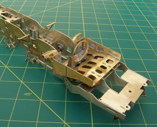
10 CHASSIS SUB-ASSEMBLIES WHEELS Attach the balance weights to the wheels as in Fig 20 - note the leading axle balance weights are handed left/right. Assemble the wheel sets, bearings and motor/gearbox selecting part F31 of appropriate thickness to control side play. The cranks on the right hand side should lead the left by 90. Now connect the motor to your pick-ups and test run. F32 F34 F33 D6 Front brake hanger and double shoe lamination (4) 8 D7 Centre and rear brake hanger and double shoe lamination (8) 8 D8 Front brake hanger and single shoe lamination (4) 8 D9 Centre and rear brake hanger and single shoe lamination (8) 8 D1O Brake pull rod 7 D11 Front brake cross shaft 6 D12 Centre and rear brake cross shaft (2) 6 D13 Centre brake cross shaft pull rod bracket (2) 1 D14 Rear brake cross shaft pull rod bracket (2) 1 D15 Brake cylinder crank lamination (2) 7 D16 LMS speedometer, mounting plate 4 D17 LMS speedometer, gearbox bracket 1 D18 LMS speedometer, gearbox front 1 D19 LMS speedometer, drive arm 8 D20 LMS speedometer, crankpin arm 8 D21 BR speedometer, drive arm 8 D22 BR speedometer, drive arm washer 8 F13 Stretcher, brake cylinder OF 7 F14 Stretcher, brake cylinder S7 7 F15 Brake shaft bracket (2) 6 F31 Axle washer (12) 4, 5 & 7 F32 Balance weight, leading axle (2) 6 F33 Balance weight, trailing axle (2) 6 F34 Balance weight, centre axle (2) 6 F33 Left Hand Side F34 F32 BRAKES Attach the steam brake cylinder (WM9) and the brake cylinder crank laminations (D15) as shown in Fig 22. Provision is made for both single brake shoes (D8 & D9) or double brake shoes (D6 & D7). Select the required parts and emboss the rivets. Laminate together using a pair of old drills in a piece of wood to align the parts. Emboss the bolts in the centre and rear brake cross shaft (D12) and solder together to the brake pull rod (D10) as a separate assembly. Add the centre brake cross shaft pull rod bracket (D13) and then the front brake cross shaft (D11). Add the rear brake cross shaft pull rod bracket (D14). Finally assemble the brake gear as shown in Fig 22. D6 D7 WM9 F13 or F14 F15 D8/9 Right Hand Side Fig 20. Wheels D15 SPEEDOMETERS The LMS speedometer is fitted as follows. Fold up the mounting bracket (D16) and the gearbox bracket (D17). Solder the gearbox bracket in place between the lower ends of the mounting bracket. Solder the drive arm (D19) to the spindle wire and trim the wire so that it is flush with the front face of the gearbox bracket. Retain the spindle in place by soldering the collar (a short piece of 1/16 tube) to the spindle. This should give a free spindle with no slop. A small hole may need to be drilled to give access for the soldering iron. Solder the gearbox front (D18) in place. Glue the dynamo casting (BR18) in place. Attach the bracket to the frame brackets as shown below. Solder the drive peg through the hole in the crankpin arm (D20) and attach the arm to the crankpin. The BR speedometer is fitted as shown in the drawing. 0.8mm wire D11 D10 D13 D12 D14 BR18 D16 D18 0.8mm wire pivot D19 D22 BR20 BR19 0.9mm copper wire Fig 22. Brakes D19 D20 0.7mm N/S wire pin D17 1/16 tube D21 Fig 21. Speedometer PC - 14
 and overlays (D3) before soldering together and to the firebox base (D1).")
11 FINISHING THE CHASSIS Attach the damper operating rod (D5)as shown in the drawing. Form the corner bends in the firebox sides/front (D2) and overlays (D3) before soldering together and to the firebox base (D1). Fold up ashpan hopper (D4) and fix in place under the firebox base in the etched groove. Add the mud hole door clamps (BR27) before attaching the complete lower firebox to the inside rear frames. Rivet and fold up the brackets - rear outside frame to footplate, left and right (F19 & F20) and solder them over the appropriate rivets on the rear frames as shown in the drawing. Similarly fit the footplate bracket, left (F26), the reach rod support bracket (F27) after drilling the hole to take a 0.8 mm wire pin and the footplate bracket, right (F28). Because of the increased frame spacing those building to Scaleseven standards will need to reduce the length of these brackets. Attach the reach rod fork joint (M39) to the reach rod (M38). The end of the fork joint must be bent over, through 180, as shown. The reach rod can now be temporarily fitted in place as shown below with pins through part M29 and F27. Fit the injectors (parts BR25 & BR26) together with their associated pipe work from 1.6 mm copper wire as shown below. The remaining pipe work shown in Fig 23, which runs under the main footplate, can now be fitted although it may be better to wait until the footplate has been constructed. The loco/tender pipe connections detailed in below are made from flexible tubing. I have provided rubber tubing for the larger pipes (over the 1.2 mm spigots) but cannot obtain similar material for the smaller pipes. I suggest you look out for some insulation from electrical wire of suitable size. Fold out the brackets for the steam sander nozzles which are on the end of the brackets attached to the spring hangers. Note once this is done the wheels are difficult to remove. The axles are now retained by the springs, formed from a triple lamination of parts F21,F22 & F23 as shown in Fig 23. Complete the chassis detailing by fitting the steam sanders (BR21) as shown in Fig 23. D2 Firebox sides and front (2) 5 D3 Firebox sides and front overlay (2) 5 D4 Ashpan hopper (2) 2 D5 Damper operating rod 7 F19 Bracket, rear outside frame to footplate- left 3 F20 Bracket, rear outside frame to footplate - right 3 F21 Spring, leading & centre axles (4) 8 F22 Spring, rear axle (2) 8 F23 Spring, outer lamination (12) 8 F25 Bracket live steam injector 5 F26 Footplate bracket, left 5 F27 Reach rod support bracket 1 F28 Footplate bracket, right 5 F30 Top feed pipe bracket (3) 5 M38 Reach rod 7 M39 Reach rod fork joint 8 BR37 BR38 BR36 0.8mm wire pins F27 F30 0.7mm wire D2/3 BR38 BR37 1.4mm wire BR36 F19 Connect to the similarly labelled pipes on the tender BR27 D5 D4 D C E F B A F20 BR26 F25 Sandpipe pipes from 0.9 mm brass and 0.4 mm copper wire BR21 Sandpipe holes F28 D4 180 fold M39 M38 F26 1.4mm wire D5 F19 BR37 WM4 Fig 23. Frame Fittings BR25 PC - 15
12 UTILITY FRONT FOOTPLATE Make the appropriate bends in the front valence before folding up and soldering together the jig. Solder the jig corner fillets (U3) in the etched grooves to strengthen the jig and to ensure that the jig is square. Fold down the front edges of the footplate (U1). If you are fitting smoke deflectors then drill out the holes shown below to fit the pegs on the lower edges of the smoke deflectors. Emboss the rivets in the footplate as shown below and fold up the splasher fronts. Carefully form the bend in the rear footplate (U32) by bending over a rod of suitable size. Now emboss the rivets on the drag beam overlay (U34) and then solder the overlay onto the drag beam (U33), before soldering the rear footplate (U32) into the slot in the drag beam. Solder this assembly in place on the jig. Solder the footplate (U1) in place. Now add the splasher tops, front, centre and rear (U12,U13 & U14). Add the following footplate overlays - under the smokebox (U4), around the front splasher left (U5), around the front splasher right (U6), around the centre splashers (U7), around the rear splasher left (U8), around the rear splasher right (U9), under the firebox (U10) and the top feed pipe flange (U11). The rear left splasher footplate overlay has two extensions that fold up as pipe clips for the 0.6 mm copper wire. Make the four access flap hinge pins from 0.4 mm copper wire. Solder two 6 BA nuts over the body fixing holes. Front splasher has a raised front to disguise the lubrication pipes Top feed pipe 1.4 mm brass wire Cut through the two bracing strips which cross the footplate and snap off the unwanted pieces along the half etched lines. This now gives a sturdy platform upon which to fit the smokebox, boiler/firebox and cab. The excess metal is not broken away until these are fitted onto the footplate. U1 Footplate 5 U2 Footplate/valence jig 1 U3 Footplate/valence jig corner fillet (4) 7 U4 Under smokebox footplate overlay 5 U5 Front left splasher footplate overlay 1 U6 Front right splasher footplate overlay 1 U7 Centre splasher footplate overlay (2) 1 U8 Rear left splasher footplate overlay 1 U9 Rear right splasher footplate overlay 1 U10 Under firebox footplate overlay 4 U11 Top feed pipe flange footplate overlay 1 U12 Front splasher top 5 U13 Centre splasher top 3 U14 Rear splasher top 3 U18 Curved front footplate, small step (2) 1 U27 Utility front footplate, angle between cylinder cover and footplate 3 U32 Rear footplate 5 U33 Drag beam 2 U34 Drag beam overlay 2 U35 Front left sandbox filler plate 1 U36 Front right sandbox filler plate 1 U37 Centre sandbox filler plate 1 U38 Rear sandbox filler plate 1 U2 BR11 BR11 BR11 BR33 Drill these red holes for smoke deflectors U33 U34 6BA nut U36 here U6 U12 U7 U13 U9 U14 U10 6BA nut U4 U35 U5 U37 U11 U38 U8 U32 For details of lubricators see Fig mm copper wire BR33 U34 U33 Fig 24. Utility Footplate PC - 16

13 To build a curved front footplate, modify the shape of the front valence on the footplate/valance jig (U2) by removing the portion shown in shaded red on the drawing below. Make the appropriate bends in the front valence before folding up and soldering together the jig. Solder the jig corner fillets (U3) in the etched grooves to strengthen the jig and to ensure that the jig is square. Break off, along the half etched line, the front edges of the footplate (U1). If you are fitting smoke deflectors drill out the holes shown in the drawing to fit the pegs on the lower edges of the smoke deflectors. If you are not fitting smoke deflectors drill out the holes shown in the drawing for the small handrails on the front footplate. Emboss the rivets in all the footplate parts as shown in the drawing and fold up the splasher fronts. Carefully form the bends in the curved front footplate (U16) and the rear footplate (U32) by bending over a rod of suitable size. Now emboss the rivets on the drag beam overlay (U34) and bufferbeam (U15). Note which bufferbeam rivets to emboss as shown in Fig 25. Solder the bufferbeam to the curved front footplate (U16) and solder in place on the jig. Solder the drag beam overlay (U34) onto the drag beam (U33), before soldering the rear footplate (U32) into the slot in the drag beam. Solder this assembly in place on the jig. File back the front edge of the footplate until it fits behind the curved front footplate (U16) before soldering it in place. Form the curved front footplate inside cylinder cover (U19) to shape, checking that it fits in the recesses in curved front footplate front frames (U17). Form inside cylinder cover overlay (U20) so that it fits over the inside cylinder cover and that the holes for inside cylinder valve tail rod covers (BR34) align. Solder the two parts together before soldering between the front frames. Solder this assembly in place. Now add the splasher tops, front, centre and rear (U12,U13 & U14). Add the following footplate overlays - under the smokebox (U4), around the front splasher left (U5), around the front splasher right (U6), around the centre splashers (U7), around the rear splasher left (U8), around the rear splasher right (U9), under the firebox (U10) and the top feed pipe flange (U11). The rear left splasher footplate overlay has two extensions that fold up as pipe clips for the 0.6 mm copper wire. Make the access flap hinge pins from 0.4 mm copper wire, the hinges are coloured green on the drawing. Solder two 6 BA nuts over the body fixing holes. U17 Front splasher has a raised front to disguise the lubrication pipes CURVED FRONT FOOTPLATE Top feed pipe mm brass wire Cut through the two bracing strips which cross the footplate and snap off the unwanted pieces along the half etched lines. This now gives a sturdy platform upon which to fit the smokebox, boiler/firebox and cab. F48 Lifting hole strengthening plate (2) 1 U1 Footplate 5 U2 Footplate/valence jig 1 U3 Footplate/valence jig corner fillet (4) 7 U4 Under smokebox footplate overlay 5 U5 Front left splasher footplate overlay 1 U6 Front right splasher footplate overlay 1 U7 Centre splasher footplate overlay (2) 1 U8 Rear left splasher footplate overlay 1 U9 Rear right splasher footplate overlay 1 U10 Under firebox footplate overlay 4 U11 Top feed pipe flange footplate overlay 1 U12 Front splasher top 5 U13 Centre splasher top 3 U14 Rear splasher top 3 U15 Front bufferbeam 4 U16 Curved front footplate 5 U17 Curved front footplate, front frame (2) 7 U18 Curved front footplate, small step (2) 1 U19 Curved front footplate, inside cylinder cover 5 U20 Curved front footplate, inside cylinder cover overlay 5 U32 Rear footplate 5 U33 Drag beam 2 U34 Drag beam overlay 2 U2 BR11 BR11 BR11 BR33 Platform handrail holes mm Drill these red holes for smoke deflectors U33 BR3 F48 U20 U28 6BA nut U4 U36 here U6 U12 U7 U13 U9 U14 U10 6BA nut U19 For details of lubricators see Fig mm copper wire F48 U35 U5 U37 U11 U38 U8 U32 U18 U20 BR35 BR33 U16 U18 NS4 NS5 U34 U33 U15 BR2 Fig 25. Curved Footplate PC - 17
 into the recesses around the window openings. Fold the rear cab corners and then curve around the small rear wings which support the cab doors.")
, by heating in a flame and bend to shape around a 0.8mm piece of wire.")
14 CAB Emboss the rivets on the cab sides/front (C1). Use photographs of your chosen prototype to determine which rivets to emboss. Solder the window beading (C2) into the recesses around the window openings. Fold the rear cab corners and then curve around the small rear wings which support the cab doors. Add the following door parts, the hinge (C11), stop (C12) and spring overlays (C13) as shown in the drawing. Anneal the hinges on the cab doors (C10), by heating in a flame and bend to shape around a 0.8mm piece of wire. The hinge pins have been made too long so that they can be bent over to stop the doors falling off. Solder the safety valves (BR22) in place in the holes in the fire box inside the cab (C16). Fold up the edges of the window frames and rivet strip (C14) and check that the sliding rear windows (C15) can be sprung in and out. Solder the window frames and rivet strip in place on the inside of the cab sides aligning the small holes for the cab side windscreens (C3). Fold up the cab seat brackets (C35) and seats (C34) and solder the brackets in place on the cab sides. Solder the front window frames (C5) in place on the inside. Form the bends between the cab sides and the cab front. Cut a slot in the cab floor (C7) to clear the reach rod - use the slot in the rear footplate (U32) as a guide. Solder two 8BA nuts to the brackets on the cab floor before folding them up. Reinforce each bend with a fillet of solder. Complete the folding of the cab floor before soldering it in place between the cab sides. Form the firebox inside the cab (C16) to shape and solder in place in the slots in the cab front. Clean off the cab front. Complete the fold lines in the front overlay (C4) by scoring deeply, fold to shape and solder in place on the cab front. If you are fitting the sand gun. drill out 0.6 mm the hole for the sand pipe in the sand bin/locker (C18) as shown in the drawing. Rivet and fold up the screw reverse base (C17) and the sand bin/locker (C18) and solder in place. Fold up the damper levers (C8) and the drain cock levers (C9) and solder in place as shown in the drawing. Curve the fall plate centre (C19) and sides (C20) and fold down the tabs which fit in the slots along the rear edge of the cab floor to give a hinge effect. Unless the curves are very generous the three parts of the fall plate will need to be soldered together to avoid the outer parts dropping between the tender and loco when going around curves. Solder the cab handrails in place. C1 Side/front 2 C2 Window beading (2) 1 C3 Side windscreen (2) 2 C4 Front overlay 5 C5 Front window frame (2) 5 C6 Handrail bracket ( ) (2) 6 C7 Floor 5 C8 Damper levers 1 C9 Drain cock lever 1 C10 Door (2) 1 C11 Door hinge overlay (4) 1 C12 Door stop overlay (2) 1 C13 Door spring bracket overlay (2) 1 C14 Window frame and rivet strip (2) 1 C15 Sliding rear window frame (2) 4 C16 Fire box inside cab 2 C17 Screw reverse base 3 C18 Sand bin for sand gun/locker 3 C19 Fall plate centre 5 C20 Fall plate side (2) 5 C34 Seat (2) 3 C35 Seat bracket (2) 1 C36 Fire Screen 4 BR22 C2 C3 C6 C3 C11 C12 0.8mm N/S wire C4 C13 Short knobs 0.8mm wire C1 C11 8BA x 3/8 screw C7 Fig 26. External View of Cab Pipe to sand gun C18 C5 C16 BR23 here 2.5mm diam C15 C14 C20 C6 C16 WM6 WM8 C7 C19 NS18 WM7 NS19 C35 C20 C36 WM7 C9 C17 C8 C4 C34 8BA nut C9 C17 Fig 27. Internal View of Cab PC - 18
 before soldering them in place as shown in the drawing. Form the cab roof (C23) to shape before soldering the roof in place on the assembly jig.")

 1 C30 Carriage warming pressure gauge 1 C31 Bracket for C29 & C30 5 C32 Bracket for C29 & C28 5 C33 Water gauge cock lever (2) 2 C36 Fire screen 4 C37 Handwheel, injector")
15 CAB ROOF & BACKHEAD Fold up the back and front roof ribs of the roof jig (C21), to give a solid base upon which to build the removable cab roof. Bend up the whistle levers on the roof ribs (C22) before soldering them in place as shown in the drawing. Form the cab roof (C23) to shape before soldering the roof in place on the assembly jig. Complete by adding the rain strip (C24) and roof ventilator front and rear (C25 & C26). Now using a carborundum disc in a mini-drill cut through the unwanted parts of the jig and snap off the redundant parts along the half etched lines. The edges of the jig will now need cleaning up. C25 C26 C23 C21 C22 C21 Roof jig 2 C22 Roof rib (2) 3 C23 Roof 2 C24 Roof rainstrip 2 C25 Roof ventilator front 5 C26 Roof ventilator rear 5 C27 Backplate shelf 7 C28 Speedometer 1 C29 Boiler pressure/vacuum gauge (2) 1 C30 Carriage warming pressure gauge 1 C31 Bracket for C29 & C30 5 C32 Bracket for C29 & C28 5 C33 Water gauge cock lever (2) 2 C36 Fire screen 4 C37 Handwheel, injector steam valve 1 C38 Handwheel, sand gun 1 C39 Handwheel, steam fountain 1 C40 Handwheel, large ejector 1 C24 BR46 C37 BR39 C39 C39 C32 BR47 C29 C29 C24 C25 C26 C23 C28 BR45 C40 NS16 C31 C30 BR44 BR40 BR41 C38 BR42 WM6 BR43 C27 C18 C22 C36 Fig 29. Cab Roof NS17 0.3mm copper wire 0.7mm copper wire 0.45mm copper wire 0.9mm copper wire 0.6mm copper wire 1.2mm copper wire Fig 32. Backplate PC - 19
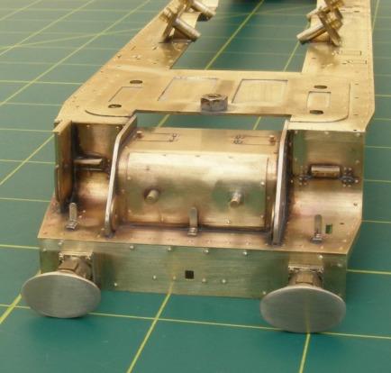
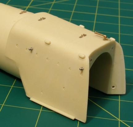
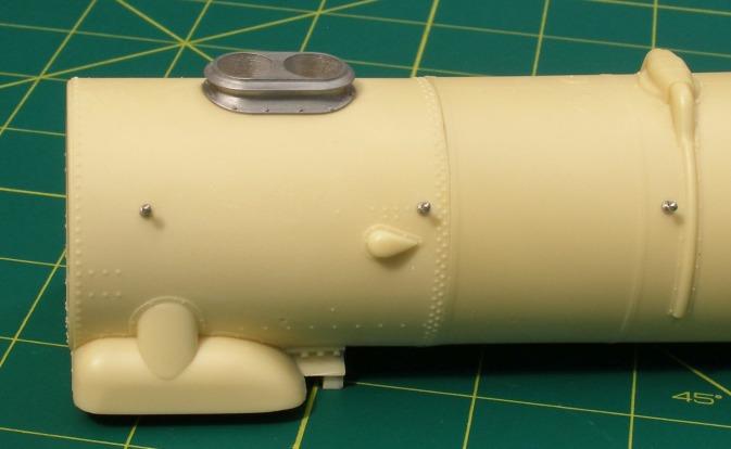
16 Before starting work on the resin castings (parts R1 & R2) please bear in mind the following: The castings should require very little finishing. They are best wet sanded, ideally using fine-grade wet and dry paper. The dust should not be inhaled and hands should be washed after work. Bonding is best done with epoxy adhesive to allow for adjustment. Wash the casings in warm water with a mild soap/non-lanolin washing-up liquid, and then rinse well before painting. Painting may be carried out with enamels, cellulose or acrylics. Of the latter two, acrylic plastic primer (Hycote brand available from car accessory shops or Halfords own brand - used for priming car plastic parts - bumpers etc.) is easier to apply than cellulose and 'keys' well. Drill the holes for the 12 self tapping screws (1/16 ) which secure the castings to the cab and footplate. Be very careful not to drill the holes for cab fixing screws too deep and break through the side of the firebox. Wrap a piece of tape around the drill at the correct depth of 6 mm to use as a guide. Drill the holes for handrail knobs (1.2 mm), vacuum ejector, steam lance cock, smokebox door handles and to clear the 6BA nut under the smokebox. All holes should be perpendicular to the surface except the rearmost hole for the vacuum ejector, which is horizontal. Attach the cab to the footplate with the 8BA screws ensuring that the curve of the cab side is hard against the curve of the footplate. Test fit the resin castings in place and check there is no gap between the rear of the firebox and the cab front. If there is a gap, remove 1 mm from the rear of the front bar underneath the smokebox and elongate the holes in the footplate for the self-tapping screws towards the cab until the holes in the smokebox and firebox are fully visible. It is important that the resin castings can be screwed to the footplate without a gap between cab and firebox or the screws through the cab front will pull the cab and rear footplate out of true. Screw the smokebox and boiler/firebox to the footplate and cab and check that the footplate is square and level and that the cab is vertical. Note that to get the boiler to sit properly on the footplate, you will need to file the inside of the splashers as indicated on the etch, particularly the middle and rear splashers. The moulded bars on the underneath of the smokebox casting will need 0.7 mm carved off the ends so that they will sit between the frames. Once you are satisfied with the fit of all components, mark across the underside join between the smokebox and boiler with a pen, remove the smokebox casting and glue the smokebox and boiler/firebox together with epoxy adhesive such that the pen marks are aligned. Immediately screw the smokebox back in place and check again that all is square while there is time for adjustment. Set aside to cure. BOILER, FIREBOX AND SMOKEBOX Now remove the unwanted material from the footplate jig in the same way as for the cab roof, and check the fit of the footplate on the chassis. It is likely that the resin boiler will need clearances made for the rear wheel flanges. Now permanently attach the cab/firebox/boiler/smokebox to the footplate. It is possible to arrange a non permanent fixing to make painting the model easier by making the handrails removable but care will be needed in handling the footplate. BR1 NS3 WM1 R2 Self tapping screws 0.8 mm N/S wire BR23 WM3 NS3 NS2 BR10 Long knobs Medium knobs BR17 R2 R1 BR mm wire Fig 30. Boiler, Firebox and Smokebox PC - 20
, front right (U36), centre (U37) and rear (U38) to the footplate with their top edges against the boiler.")
 4 U40 Smoke")
 is problematic but achievable as the photograph shows.")


17 FOOTPLATE DETAILING AND SMOKE DEFLECTORS FOOTPLATE DETAILING Refer to Fig 24 & 25. Fit riveted strip U28 on top of the inside cylinder cover against the bottom of the resin smokebox. Fit the sandbox filler plates, front left (U35), front right (U36), centre (U37) and rear (U38) to the footplate with their top edges against the boiler. Then fit the sandbox filler pipe and lids (BR11). Add the top feed pipe from 1.4 mm brass wire. U35 Sandbox filler plate front left 1 U36 Sandbox filler plate front right 1 U37 Sandbox filler plate centre 1 U38 Sandbox filler plate rear 1 U39 Silvertown lubricator hand lever (4) 4 U40 Smoke deflector, curved front footplate (2) 3 U41 Smoke deflector, curved front footplate lower section (2) 5 U42 Smoke deflector, utility front footplate (2) 3 U43 Smoke deflector, bracket to smokebox (2) 4 BR3 0.8mm wire pin NS5 Fig 32. Buffers SMOKE DEFLECTORS The lubrication system (Fig 31) is problematic but achievable as the photograph shows. The castings are provided with threaded pins (14BA and 10BA) so that they can be made removable. Suitable nuts are not provided. The lubricators on the right hand side are turned around through 180 so that the lid hinges from the forward side. The pipe runs need not be continuous - breaks can be disguised behind the sand box filler plates. The splasher behind the three central lubricators is painted body colour and lined. If appropriate fit the smoke deflectors as shown in the drawing. To ease painting they can be made removable by arranging for the handrails to slide out. The brackets which bend over the handrails and are soldered on the inside, should be annealed in the same way as the cab door hinges. After May 1955 the smoke deflectors fitted to most of the curved front locomotives have footholds fitted. Use the Utility smoke deflector (U42) as a template BR15 U39 BR12 BR13 BR14 BR16 U43 BR4 U40 0.3mm copper wire Fig 31. Lubricators 0.45mm copper wire BR5 Footholds 0.7mm wire Score a fold line here. Remove the shaded section after scoring the line U41 U42 Now permanently attach the cab/firebox/boiler/smokebox to the footplate. It is possible to arrange a non permanent fixing to make painting the model easier by making the handrails removable but care will be needed in handling the footplate. Attach all the remaining parts as shown in the diagrams. The buffers are prevented from rotating by a 0.8 mm wire pin which locates in the slot in part NS5, as shown in Fig. 32. Fig 33. Smoke Deflectors PC - 21
18 PC - 22
19 ETCH SHEET 1 & 2 C8 C9 C13 C12 C30 C29 U31 F10 U11 M4 F48 F40 U18 C11 C28 U30 U29 D18 D17 M5 C10 C2 U9 U8 U2 C35 U38 U37 U35 C14 U36 U7 M3 M2 U5 U6 C40 C39 U31 F10 F27 U23 D13 D14 M23 C38 U30 U29 M26 C3 T4 C16 C24 F9 C33 T4 T9 D4 F50 F51 F49 C1 C21 C23 U34 T5 U33 T2 C6 PC - 23
20 ETCH SHEET 3 & 4 U27 U28 B4 U40 U42 T7 F8 F4 C22 C18 C34 F43 U13 U14 F20 C17 F19 F3 F24 T6 B13 T11 U15 D16 T10 U25 F45 F46 F47 U39 D1 B6 T3 B14 C36 T1 U43 T12 U10 B8 F31 U4 T8 C15 F44 PC - 24
21 ETCH SHEETS 5 D2 D3 F30 B11 C7 U21 U16 U32 C20 F31 C4 U12 F25 F26 U41 C32 C25 U1 C5 U24 U26 C19 B12 U22 U20 U19 F52 F28 C31 C26 PC - 25
22 ETCH SHEET 6 F1 M11 F5 M10 F34 F32 F33 D11 D12 F15 F6 F2 B5 F36 F35 F18 PC - 26
23 DUCHESS ETCH SHEET 7 F38 F39 U3 F12 F11 F14 F13 U17 M20 D15 B2 M1 F17 B7 F16 B1 C27 B3 M9 B9 B10 F41 F42 F37 M8 F31 F7 M7 M6 F29 D5 M38 D10 PC - 27
24 ETCH SHEET 8 M19 M27 M31 M15 M17 M24 M25 M14 M16 F23 F22 F21 M28 M34 M36 M32 M13 M35 M29 M12 M30 M26 M37 M22 D7 D8 D9 D22 D21 D19 D20 D6 M18 M33 M39 M21 PC - 28

 1 BR4 Smoke deflector hand hold (4) 3 BR5 Smoke deflector foot hold (2) 1 BR6 Bogie bearer")
 1, 3 BR12 Mechanical lubricator (4) 3 BR13 Mechanical")

 3, 7 BR25 Exhaust steam injector 6 BR26 Live steam injector 8 BR27 Mud hole door clamp (2) 7 BR28 Slide bar")
 7 BR32 Cylinder drain cock (6) 3, 7 BR33 Drag beam rubbing plate 5 BR34 Inside cylinder valve tail")


 NS7 NS19 NS15 NS5 WM6 WM7 WM8 Back plate Screw reverse stand Screw reverse gear case WM1 NS10 NS1")
 3 NS2 Smokebox door handles 2 NS3 Smokebox lamp bracket")
 3 NS9 Front valve chest cover (2) 3 NS10 Rear cylinder cover/stuffing box (2) 1 NS11 Front cylinder")

25 CAST PARTS BR24 4 BR BR35 8 BR11 BR3 BR10 BR6 BR2 BR5 BR37 BR22 BR13 BR2 BR30 BR11 BR29 BR2 BR21 BR40 BR44 BR14 BR32 BR43 BR4 BR47 BR12 BR46 BR33 BR45 BR18 BR1 BR42 BR23 BR39 BR17 BR20 BR19 BR8 BR9 BR25 BR21 BR32 BR34 BR31 BR15 BR24 BR28 BR27 BR38 BR36 BR26 BR16 BR7 BRASS CASTINGS BR1 Steam lance cock 5 BR2 Vacuum pipe - 3 parts 2 BR3 Buffer housing (2) 1 BR4 Smoke deflector hand hold (4) 3 BR5 Smoke deflector foot hold (2) 1 BR6 Bogie bearer bracket (2) 1 BR7 Bogie bearer pad (2) 1 BR8 Bogie side control stop - left 5 BR9 Bogie side control stop - right 5 BR10 Vacuum ejector 2 BR11 Sandbox filler pipe and lid (6) 1, 3 BR12 Mechanical lubricator (4) 3 BR13 Mechanical lubricator lid (4) 3 BR14 Mechanical lubricator arm (4) 3 BR15 Front lubricator (2) 7 BR16 Rear lubricator (2) 7 BR17 Pipes from cab front 5 BR18 LMS speedometer dynamo 5 BR19 BR speedometer - upper gearbox 5 BR20 BR speedometer - lower gearbox 5 BR21 Steam sander - (6) 7 BR22 Safety valve - (4) 3 BR23 Whistle 5 BR24 Boiler band joining bracket (6) 3, 7 BR25 Exhaust steam injector 6 BR26 Live steam injector 8 BR27 Mud hole door clamp (2) 7 BR28 Slide bar lubricator (2) 7 BR29 Valve chest snifting valve (4) 3 BR30 Cylinder relief valve (4) 3 BR31 Outside cylinder valve tail rod cover (2) 7 BR32 Cylinder drain cock (6) 3, 7 BR33 Drag beam rubbing plate 5 BR34 Inside cylinder valve tail rod cover (2) 7 BR35 Inside cylinder inspection cover knob (2) 7 BR36 Vacuum pipe flange 7 BR37 Feed pipe flange (2) 3 BR38 Exhaust injector control pipe flange 7 BR39 Steam fountain 4 BR40 Blower valve 4 BR41 Sand gun 4 BR42 Combined steam & vacuum brake 4 BR43 Steam sanding control 4 BR44 Continuous blow down valve 4 BR45 Ejector valve 4 BR46 Water gauge - left 4 BR47 Water gauge - right 4 1 NS4 2 NS17 3 WHITE METAL CASTINGS NS12 NS6 NS8 WM1 WM2 Smokebox door Single chimney WM3 WM2 WM6 NS3 NS2 NS13 NS11 NS9 WM3 Double chimney WM4 Exhaust steam injector pipe WM5 Trailing truck axle box (2) NS7 NS19 NS15 NS5 WM6 WM7 WM8 Back plate Screw reverse stand Screw reverse gear case WM1 NS10 NS1 NS16 NS14 WM9 Steam brake cylinder WM10 Front valve chest - left WM11 Front valve chest - right WM4 NS1 RESIN CASTINGS NICKEL SILVER CASTINGS NS1 Trailing truck spring (2) 3 NS2 Smokebox door handles 2 NS3 Smokebox lamp bracket 2 NS4 Footplate lamp bracket (3) 1 NS5 Buffer (2) 3 NS6 Slide bar - upper (2) 2 NS7 Slide bar - lower (2) 2 NS8 Rear valve chest (2) 3 NS9 Front valve chest cover (2) 3 NS10 Rear cylinder cover/stuffing box (2) 1 NS11 Front cylinder cover (2) 3 NS12 Crosshead/ piston rod (2) 1 NS13 Valve rod (2) 3 NS14 Return crank (2) 3 NS15 Union link (2) 3 NS16 Regulator handle 2 NS17 Firebox doors handle 2 NS18 Screw reverse handle 2 NS19 Screw reverse indexing plate 2 R1 Boiler/firebox R2 Smokebox WM8 WM7 WM5 WM9 WM10 WM11 PC - 29
FINNEY7. 24 Jul 18 A3-4 LNER A3. Fig 1. General Arrangement
 Fig 1. General Arrangement - 4 COUPLING RODS. The coupling rods are now made so that they can be used as a jig to align the hornguides accurately. First drill out all the crankpin holes to a convenient
Finney7 BEYER PEACOCK BUILT LOCOMOTIVE
 BEYER PEACOCK BUILT LOCOMOTIVE Fig 1. Beyer, Peacock Built Locomotive Nos. 415-426 Depicted as built with short tanks, blower valve on the left, small dome, low tank front, 3 0 trailing wheels, snap head
FINNEY7. 24 Jul 18 4 LNER A4. Fig 1. A4 GA Drawing
 Fig 1. A4 GA Drawing 24 Jul 18 4 COUPLING RODS & FRAME PREPARATION Coupling rods. The coupling rods are made so that they can be used as a jig to align the horn blocks accurately. First drill out all the
Brassmasters Scale Models
 Brassmasters Scale Models www.brassmasters.co.uk L&SWR/SOUTHERN RAILWAY DRUMMOND M7 0-4-4T LOCOMOTIVE KIT Designed by Martin Finney 4MM SCALE OO - EM - P4 INSTRUCTIONS AND PROTOTYPE NOTES PO Box 1137 Sutton
ALAN GIBSON, THE BUNGALOW CHURCH ROAD, LINGWOOD, NORWICH, NORFOLK. MIDLAND/L.M.S. Class 4F.
 ALAN GIBSON, THE BUNGALOW CHURCH ROAD, LINGWOOD, NORWICH, NORFOLK MIDLAND/L.M.S. Class 4F. These instructions and history should be carefully studied BEFORE starting on any assembly. The standard kit is
Dinorwic Quarry Hunslet `Alice Class with cab 7mm Scale kit for 16.5mm or 14mm Gauge
 EDM Models 19 Briar Avenue, Acomb, York. Y026 5BX Dinorwic Quarry Hunslet `Alice Class with cab 7mm Scale kit for 16.5mm or 14mm Gauge Introduction This kit, which has been researched by Jonathan Matthews
Stephenson's Valve Gear: 7mm cast white-metal kit 19 th Century swing-link version - non-working, cosmetic only. Instructions
 SER-Kits Stephenson's Valve Gear: 7mm cast white-metal kit 19 th Century swing-link version - non-working, cosmetic only Page 1 of 5 Instructions HEALTH & SAFETY: The castings contain some lead. Dispose
BRL CLASS 66 LOCOMOTIVE. Building Instructions
 Tel 07807225801 prmrp@fsmail.net www.prmrp.com BRL - 066 CLASS 66 LOCOMOTIVE Building Instructions SCALE MODEL PRODUCT FOR ADULT MODELLERS ONLY. WHITE METAL CONTAINS LEAD WASH HANDS AFTER USE. MAY CONTAIN
- 0 Gauge - Southern Railway Class 02 Chassis Construction & Parts Identification
 - 0 Gauge - Southern Railway Class 02 Chassis Construction & Parts Identification I would recommend constructing the body to the fitting of parts 42 before starting chassis construction. As the basic body
British Railways Standard Locomotives Microfilm Lists. British Railways Standard Locomotives Derby Microfilm List
 British Railways Standard Locomotives Microfilm Lists British Railways Standard Locomotives Derby Microfilm List Drawings 26047 to 26073 have had their original Timken drawing number added to the description.
RT Models. 4mm scale, 00/EM/P4 Manning Wardle, class K 0-6-0ST loco kit
 1 RT Models 4mm scale, 00/EM/P4 Manning Wardle, class K 0-6-0ST loco kit History The first of Manning Wardle s Class K was built in 1864. Many of these locos were mainly built for contractors with only
MANNING WARDLE ex-penrhyn Quarry Railway Narrow Gauge `Jubilee mm Scale kit for 16.5mm or 14mm Gauge
 EDM Models 19 Briar Avenue, Acomb, York. Y026 5BX MANNING WARDLE ex-penrhyn Quarry Railway Narrow Gauge 0-4-0 `Jubilee 1897 7mm Scale kit for 16.5mm or 14mm Gauge Introduction This kit, which was researched
NSWGR C30T LOCOMOTIVE AND TENDER KIT
 Australian Railway Kits ABN: 27 416 246 418 Incorporating Main West Models Manufacturers, Wholesalers and Retailers of Quality Australian Model Railways PO Box 252 Warwick, Queensland, 4370 Australia Phone/Fax:
The 2mm Scale Association etched replacement chassis for RTR loco bodies
 The 2mm Scale Association etched replacement chassis for RTR loco bodies Required Parts List Chassis etch (supplied) Motor - for all designs the Association can motor is suitable, alternatives are shown
MKD 08 BR 21.5 TON FLYASH HOPPER. Wagon Kit To cover Vacuum (CSV) and air braked types (CSA)
 and air braked types (CSA)") 1 MKD 08 BR 21.5 TON FLYASH HOPPER. Wagon Kit To cover Vacuum (CSV) and air braked types (CSA) History. Pulverised fuel ash (PFA), know as fly ash which is a by-product from the combustion process in coal
1 MKD 08 BR 21.5 TON FLYASH HOPPER. Wagon Kit To cover Vacuum (CSV) and air braked types (CSA) History. Pulverised fuel ash (PFA), know as fly ash which is a by-product from the combustion process in coal
1. Invert the tender, and hold in a suitable device. We use a foam cradle the Peco loco service cradle being ideal.
 Bachmann J11 EM Finescale Conversion Before you start, it is a good idea to have some small containers or snap top poly bags to put screws and components in for safe keeping...much better than crawling
BRL-142/143 Class 142/143. Building Instructions
 Peter Besant Tel 07807225801 prmrp@fsmail.net www.prmrp.com BRL-142/143 Class 142/143 Building Instructions SCALE MODEL PRODUCT FOR ADULT MODELLERS ONLY. WHITE METAL CONTAINS LEAD WASH HANDS AFTER USE.
NSWGR Z Tank Locomotive
 Australian Railway Kits ABN: 27 416 246 418 Incorporating Main West Models Manufacturers, Wholesalers and Retailers of Quality Australian Model Railways PO Box 252 Warwick, Queensland, 4370 Australia Phone/Fax:
4mm scale 009 gauge Lodge Hill & Upnor railway Chattenden Drewry loco body kit.
 RT Models 4mm scale 009 gauge Lodge Hill & Upnor railway Chattenden Drewry loco body kit. HISTORY The loco was supplied by the Drewry car co. to the Lodge Hill & Upnor Railway in 1949, works number 2263.
NSWGR C LOCOMOTIVE AND TENDER KIT
 Australian Railway Kits ABN: 27 416 246 418 Incorporating Main West Models Manufacturers, Wholesalers and Retailers of Quality Australian Model Railways PO Box 252 Warwick, Queensland, 4370 Australia Phone/Fax:
Norden. A Lancashire Mill Engine. Scale: 1:12
 Scale: 1:12 Neil M. Wyatt February 2009 Fig. 1: General Arrangement General Arrangement Sheet: 1 An Old Steam Engine DEAR SIR, In the ruins of an old mill at, near Rochdale, there is an old steam engine
Locomotive parts April 2018
 Locomotive parts April 2018 CONTENTS Page GNR Detail parts 3 LBSC Detail parts 4 GWR Detail parts 5 LMS Detail parts 10 LNER Detail parts 13 GER Details Parts 13 BR castings 14 Tooling & spares 15 2 GNR
BRL-007 Detailing and Conversion Kit for NOVO/Triang Class 35 Hymek. Building Instructions
 Peter Besant Tel 07807225801 prmrp@fsmail.net www.prmrp.com BRL-007 Detailing and Conversion Kit for NOVO/Triang Class 35 Hymek Building Instructions SCALE MODEL PRODUCT FOR ADULT MODELLERS ONLY. WHITE
Bachmann GWR Earl (Dukedog) EM Finescale Conversion
 EM Finescale Conversion") Bachmann GWR Earl (Dukedog) EM Finescale Conversion Before you start, it is a good idea to have some small containers or snap top poly bags to put screws and components in for safe keeping...much better
Bachmann GWR Earl (Dukedog) EM Finescale Conversion Before you start, it is a good idea to have some small containers or snap top poly bags to put screws and components in for safe keeping...much better
PYRTE. Building The Front Axle, Fork and Steering
 PYRTE Building The Front Axle, Fork and Steering The front axle on this traction engine is a very simple affair, in that it is a rectangular steel rod, sat on edge, with a pivot in the centre, which is
Victorian Railways X Class Locomotive and tender kit
 Victorian Railways X Class 2-8-2 Locomotive and tender kit Ref.E226A&B and E227, Manufactured by DJH exclusively for Steam Era Models Introduction The first X class Heavy Mikado, number 27, entered traffic
Bowaters cab. Rear half of tropical cab frame. Cab door 82. Bend tags and solder to cab rear in open or closed position.
 Bowaters cab 29 32 44 31 Rear half of tropical cab frame 22 27 Cab door 82. Bend tags and solder to cab rear in open or closed position. 20 21 33 Side rod fitting and valve gear - Stephensons 44 0.7mm
9 Locomotive Compensation
 Part 3 Section 9 Locomotive Compensation August 2008 9 Locomotive Compensation Introduction Traditionally, model locomotives have been built with a rigid chassis. Some builders looking for more realism
Wheels, paint and transfers required to complete. Please note that to aid the folding of the various parts score all the halfetched fold lines.
 Furness Railway Wagon Co. Furness Railway/LMS 45ton All Steel Bogie Iron Ore Hopper Wagon Built by The Pressed Steel Car Co. Pittsburgh, Pennsylvania, USA Circ. 1899 Wheels, paint and transfers required
(WW03f) BR PIPE WAGON 4 shoe brake
 BR PIPE WAGON 4 shoe brake") (WW03f) BR PIPE WAGON 4 shoe brake History. The pipe wagons were built to four basic diagrams sharing the same basic dimensions. The first 300 pipe wagons were built at Derby works to diagram 460, and
(WW03f) BR PIPE WAGON 4 shoe brake History. The pipe wagons were built to four basic diagrams sharing the same basic dimensions. The first 300 pipe wagons were built at Derby works to diagram 460, and
Bachmann D11 EM/S4 Finescale Conversion
 Bachmann D11 EM/S4 Finescale Conversion Before you start, it is a good idea to have some small containers or snap top poly bags to put screws and components in for safe keeping...much better than crawling
Class BR Class 03/04 Shunter. Foldup
 Crank overlays The 2mm Scale Association BR Class 03/04 Shunter Bachmann replacement chassis Inside frames gearbox 3-680 Class 03 Class 04 coupling rods Bachmann etched replacement 03/04 chassis etch 30:1
Brassmasters Scale Models
 Brassmasters Scale Models www.brassmasters.co.uk Cleminson 6-wheel underframe kit PO Box 1137 Sutton Coldfield B76 1FU Copyright Brassmasters 2016 1 Introduction 1.1 The purpose of this booklet is to guide
Heljan EM Finescale Conversion.
 Heljan 02 2-8-0 EM Finescale Conversion. Before you start, it is a good idea to have some small containers or snap top poly bags to put screws and components in for safe keeping...much better than crawling
Welcome Wagons WW ton Mineral (2 & 4 shoe brake)
") Welcome Wagons WW13 16 ton Mineral (2 & 4 shoe brake) HISTORY The 16T open mineral wagon was the most numerous type built by BR from 1950 to 1957, the first diagram being 108, although there was 16T steel
Welcome Wagons WW13 16 ton Mineral (2 & 4 shoe brake) HISTORY The 16T open mineral wagon was the most numerous type built by BR from 1950 to 1957, the first diagram being 108, although there was 16T steel
Mamod SL1K Locomotive Assembly Instructions
 Mamod SL1K Locomotive Assembly Instructions LOCOMOTIVE ASSEMBLY INSTRUCTIONS To ensure ease of construction reference to these instructions are essential. All the major parts are in the front of the box
Hornby Railroad Crosti 9F EM Finescale Conversion.
 Hornby Railroad Crosti 9F EM Finescale Conversion. Before you start, it is a good idea to have some small containers or snap top poly bags to put screws and components in for safe keeping...much better
SEARAILS RR-XXX STEAM LOCOMOTIVES ASSEMBLY MANUAL
 SEARAILS RR-XXX 0-4-0 STEAM LOCOMOTIVES ASSEMBLY MANUAL 30 March 2015 T R Knapp Model Engineering 1 This diagram shows basic assembly of Nn3/Z Porter 0-4-0T 2 This diagram shows basic assembly of Baldwin
Chopper Couplings. Assembly. Fitting
 Chopper Couplings Unlike most model chopper couplings, these will work with two opposing hooks, which looks so much better and allows you to turn stock at will. They are still compatible with most other
FUSELAGE ASSEMBLY SECOND SECTION (of three)
") FUSELAGE ASSEMBLY SECOND SECTION (of three) 1 FRONT FLOOR ASSEMBLY The front floor assembly is fabricated from three pieces of the two ply pre-pregnated panel material supplied. The basic floor panel and
FUSELAGE ASSEMBLY SECOND SECTION (of three) 1 FRONT FLOOR ASSEMBLY The front floor assembly is fabricated from three pieces of the two ply pre-pregnated panel material supplied. The basic floor panel and
WW03e Welcome Wagons 8 Shoe Brake Pipe Wagon
 WW03e Welcome Wagons 8 Shoe Brake Pipe Wagon History The pipe wagons were built to four basic diagrams sharing the same basic dimensions. The first 300 pipe wagons were built at Derby works to diagram
Brake Blocks Product Code BB_7. Brake Blocks Product Code BB_7. A product from: A product from:
 Brake Blocks Product Code BB_7 The brake block types provided by these etchings are: Early sin gle sided brakes (three 4 shoe Early ei ther sided brakes ( one 4 shoe set) Later ei ther sided brakes ( three
Bachmann. Climax. Phoenix Sound Systems, Inc West Liberty Road Ann Arbor MI
 Bachmann Climax Phoenix Sound Systems, Inc. 3514 West Liberty Road Ann Arbor MI 48103 www.phoenixsound.com phone: 800-651-2444 fax: 734-662-0809 e-mail: phoenixsound@phoenixsound.com 2004-2007 Phoenix
Furness Railway Coach Co.
 Furness Railway Coach Co. Outside Framed Coaches Paint and transfers required to complete. Part 32 Part 7/8 Part 9 Part 6 Part 31 Part 14 The Parts. Part 19 Parts 20/21/22 Part 5 Part 4 Part 1 Part 3 Part
Build your own THUNDERBIRD 2
 PACK 03 PAGE 12 Pod 3 front hatch and Elevator Car 2 43 13 Pod 3 rear hatch and Elevator Car 2 46 14 Pod 3 floor and Elevator Car 2 49 15 Pod 3 frames and FAB 1 52 16 Pod 3 frames and FAB 1 55 17 Pod 3
Furness Railway Wagon Co.
 Furness Railway Wagon Co. The Parts. S&DJR/LMS/BR 20ton 6-Wheel Brake van Wheels, paint and transfers required to complete. Parts 13/15 Bolts/nuts/ washers Part 22 Part 5 Parts 10/19/20/21/ 23/24/25 Part
Micro-Trains #1021/#1022 Low short profile coupler
 1 Micro-Trains #1021/#1022 Low short profile coupler Low short profile coupler, for locomotives and cars with limited mounting area, makes 2 pair of either (1021) Life-Like E8A Pilot or Bachmann 4-8-4
Completion Of Heritage Annual Inspection Steam Locomotives
 Page 1 of 10 Completion Of Heritage Annual Inspection Steam Locomotives This cover sheet is to be completed by the inspector for each Heritage Vehicle inspected. The Heritage Vehicle Provider is to provide
11 - Fairings. Fairings. February XLF Page 11-1
 11 - Fairings Fairings February 2003 11-XLF Page 11-1 11 - Fairings This Page Intentionally Left Blank Page 11-2 11-XLF February 2003 11 - Fairings Contents 11.0 - Chapter Preface... 11-4 11.0.1 - Parts
Tip: LED Lighting for the 4367 SBB Euro City Set, 4366 and 4368 Cars Date: , Corrections Modified , Photos
 Hi All, I have had the 4367 SBB Euro City set with extra cars 4366 and 4368 since 1998, apart from a test run on the layout they have stayed in storage ever since. I decided to change some rolling stock
Build your own THUNDERBIRD 2
 PACK 01 STAGE PAGE 01 Nose assembly and Elevator Car rear wheels 3 02 Cockpit interior and Elevator Car 1 completion 7 03 Missile launcher and Thunderbird 4 11 04 Nose assembly and the Tracy brothers 15
INSTRUCTIONS FOR NYC K-11 PACIFIC KIT #100200
 INSTRUCTIONS FOR NYC K-11 PACIFIC 4-6-2 KIT #100200 These instructions provide photographs of completed model, exploded-view drawings, diagrams, step-by-step instructions and an itemized parts list. If
Hornby Railroad Hall EM Finescale Conversion.
 Hornby Railroad Hall EM Finescale Conversion. The subject of this sheet is the new (2015) Hornby Railroad Hall. There are several specification and livery variants, but all have a common chassis and as
Instructions for Assembling Driving Wheels, Axles and Crankpins
 Instructions for Assembling Driving Wheels, Axles and Crankpins (Version 1; October 2008) Introduction These instructions explain how to assemble Exactoscale 4mm scale driving wheels, axles and crankpins
Houstoun Gate Locomotive Works Gordon 4-Wheel Drive Chassis Assembly Instructions
 Houstoun Gate Locomotive Works Gordon 4-Wheel Drive Chassis Assembly Instructions It is suggested that you read these instructions through before commencing construction. A minimum of tools are needed
Furness Railway Wagon Co.
 Furness Railway Wagon Co. Great Eastern Railway/LNER/BR 1900 Diagram 7 10ton Cattle Van Steel Under-Frame Wheels, paint and transfers required to complete. Please note that to aid the folding of the various
Chevrolet 3100 IFS Kit
 1947-54 Chevrolet 3100 IFS Kit Congratulations on your purchase on what we believe is the finest IFS kit available for 1947-54 Chevrolet pickups with stock frames. We have invested many hours into designing
Hornby GWR Star Class EM Finescale Conversion.
 Hornby GWR Star Class EM Finescale Conversion. Before you start, it is a good idea to have some small containers or snap top poly bags to put screws and components in for safe keeping...much better than
10. Lower Fuselage Assembly Undercarriage
 10. Lower Fuselage Assembly Undercarriage Undercarriage 10.27 2 230399 0 Jabiru Undercarriage Configurations There are four combinations of tyres available, utilising two sets of hubs (standard and heavy
Bag 1. Bag 1. Center Pivot. Center Pivot
 8 00734 01901 5 Center Pivot Bag 1 3374 - Center Pivot Socket 4019 - Alum Pivot ball 3254-2-56 Button Head *Note - Sometimes it is helpful to slightly over-tighten the top clamp screws, then work the ball
Bachmann 1F (Half Cab) EM Finescale Conversion
 EM Finescale Conversion") Bachmann 1F (Half Cab) EM Finescale Conversion Before you start, it is a good idea to have some small containers or snap top poly bags to put screws and components in for safe keeping...much better than
Bachmann 1F (Half Cab) EM Finescale Conversion Before you start, it is a good idea to have some small containers or snap top poly bags to put screws and components in for safe keeping...much better than
Application Note. Atlas RS-3 Tsunami Digital Sound Decoder Installation Notes
 Application Note Atlas RS-3 Tsunami Digital Sound Decoder Installation Notes Overview This application note describes how to install a TSU-AT1000 digital sound decoder into an HO Atlas RS-3. Skill Level
Hornby 08 Diesel Shunter EM Finescale Conversion.
 Hornby 08 Diesel Shunter EM Finescale Conversion. Before you start, it is a good idea to have some small containers or snap top poly bags to put screws and components in for safe keeping...much better
Lower Fuselage Assembly. Controls
 Lower Fuselage Assembly Jabiru Aircraft Controls Lower Fuselage Assembly 10.11 3 051000 1 Assemble & Fit Control References: Drawings 3000092-7 and 93000K4/1 see (10.12) Photo 10.11(a) to 10.11(i) Parts
Page: MEMO: In Figure 3, "2X 1 3/32 [27.78 mm]" was "2X 1 3/32 [2.75 mm]"
![Page: MEMO: In Figure 3, 2X 1 3/32 [27.78 mm] was 2X 1 3/32 [2.75 mm]](/thumbs/73/68816766.jpg "Page: MEMO: In Figure 3, 2X 1 3/32 [27.78 mm] was 2X 1 3/32 [2.75 mm]") 14401 Keil Road NE, Aurora, Oregon, USA 97002 PHONE 503-678-6545 FAX 503-678-6560 www.vansaircraft.com info@vansaircraft.com Service Letters and Bulletins: www.vansaircraft.com/public/service.htm REVISION
14401 Keil Road NE, Aurora, Oregon, USA 97002 PHONE 503-678-6545 FAX 503-678-6560 www.vansaircraft.com info@vansaircraft.com Service Letters and Bulletins: www.vansaircraft.com/public/service.htm REVISION
1 Engine nacelle kit with outrigger for A 10 and similar models 7249 /52 1 Taper collet, 3.17 mm bore, 2 locking screws and cap nut 7249 /69
 Instructions for Order no. 249/51 The impeller unit was developed by our team of experienced model flyers for semiscale electric-powered model jets. The result is that the is designed specifically to cater
Build the. Steam Locomotive. Pack 01
 Build the Steam Locomotive Pack 01 Build the Steam Locomotive Contents Step by step Stage 01: The smokebox door Stage 02: The smokebox Stage 03: The first driving wheels and coupling rods Stage 04: The
Hinges and Flap Fittings Furniture Hinges
 Butt hinge Material: Steel Length: 50 mm Flange thickness: 1.5 mm Barrel Ø: 8 mm Crank A, straight Ø Gap1 mm Mounting Nickel plated matt Left 1.08.717 Right 1.08.708 Brass plated Left 1.08.511 Right 1.08.502
Instructions: PRR Sam Rea Shops X58 Class Box Car Kit Tangent Part Numbers: XX through XX 9/2015
 Instructions: PRR Sam Rea Shops X58 Class Box Car Kit Tangent Part Numbers: 14000-XX through 14002-XX 9/2015 Thank you for purchasing the Tangent Scale Models PRR Sam Rea Shops X58 Class Box Car Kit! A
1:8 scale Koban Model Documentation
 1:8 scale Koban Model Documentation Gear-foot assembly The gear foot consists of three parts, the gear-foot, prop shaft, and propeller. Clean flash from castings being careful to keep the mating surfaces
Caley Coaches True Line kits in etched brass
 Caley Coaches True Line kits in etched brass 0141-772 37 Jim Smellie, 1 Tay Crescent, Bishopbriggs, Glasgow, G64 1EU. Jim Smellie Nov. 1992 10' Building Instructions for kit CC20 Caledonian Railway 1 Ton
Furness Railway Wagon Co. Glasgow & South Western Railway/LMS/BR 12ton Mineral Steel Under-Frame
 Furness Railway Wagon Co. Glasgow & South Western Railway/LMS/BR 12ton Mineral Steel Under-Frame Wheels, paint and transfers required to complete. Please note that to aid the folding of the various parts
AIRCRAFT LANDING GEAR CONSTRUCTION MANUAL
 APPENDIX AI KITPLANES FOR AFRICA AIRCRAFT LANDING GEAR CONSTRUCTION MANUAL Revision: C September 2008 Page L1 of 20 NOTE: Please read the General Manual before proceeding. Please read through the entire
A B C D E F. Tools Required (supplied by others)
") Page 1 of 17 Parts List Below Deck Automatic Retractable Security Cover Kit (1) Tube End Bearing Plate (A) (1) Rope Reel and Cover Drum Motor Assembly (B) (1) Cover Drum (1) Pulley Support Channel (2)
Page 1 of 17 Parts List Below Deck Automatic Retractable Security Cover Kit (1) Tube End Bearing Plate (A) (1) Rope Reel and Cover Drum Motor Assembly (B) (1) Cover Drum (1) Pulley Support Channel (2)
Owner s Manual: Standard Gauge Diesel shunter Locomotive in Gauge 3 scale. PLine. Built in Brass. Standard Gauge Shunter Locomotive Model (G3 scale)
") PLine Built in Brass Standard Gauge Shunter Locomotive Model (G3 scale) PLEASE READ THIS OWNERS MANUAL CAREFULLY BEFORE OPERATING THE MODEL Prototype Information: Not many Standard gauge locomotives operated
PLine Built in Brass Standard Gauge Shunter Locomotive Model (G3 scale) PLEASE READ THIS OWNERS MANUAL CAREFULLY BEFORE OPERATING THE MODEL Prototype Information: Not many Standard gauge locomotives operated
In area - A -, a proper seal must be made against the top of the window glass.
 Door window, adjusting Page 1 of 3 Audi > B3 > 1994-1998 Body Exterior, Interior 61 - Convertible top, checking and adjusting Door window, adjusting Sections C-C and D-D. Adjust door window so that window
R O A D S M I T H TRIKE CONVERSIONS BY THE TRIKE SHOP
 R O A D S M I T H TRIKE CONVERSIONS BY THE TRIKE SHOP Please thoroughly review the instructions before and during installation. Keep in mind that this product was designed to be installed by trained dealer
FUNCTION OF A BEARING
 Bearing FUNCTION OF A BEARING The main function of a rotating shaft is to transmit power from one end of the line to the other. It needs a good support to ensure stability and frictionless rotation. The
RADIO CONTROL MODEL HURRICANE
 RADIO CONTROL MODEL VQAA040G VQAA040B HURRINE Almost ready to fly SPECIFITIONS Wingspan...63 in. / 161cm Length...50 in. / 129cm Engine...50~60 2T / 70~90 4T Or Electric equivalent. RC Functions: Motor
R O A D S M I T H TRIKE CONVERSIONS BY THE TRIKE SHOP
 R O A D S M I T H TRIKE CONVERSIONS BY THE TRIKE SHOP Please thoroughly review the instructions before and during installation. Keep in mind that this product was designed to be installed by trained dealer
Parts Price List. B 1 LMS/BR Parallel. (Round) B 8 LSWR Round base B 2 GWR/BR Parallel B 9 Pre Grouping Round Base Parallel.
 B 8 LSWR Round base B 2 GWR/BR Parallel B 9 Pre Grouping Round Base Parallel.") Parts Price List Please note that parts that have no price against them are not yet available. Also, I will be adding to the list, and would welcome any suggestions for parts that you may think are needed.
Parts Price List Please note that parts that have no price against them are not yet available. Also, I will be adding to the list, and would welcome any suggestions for parts that you may think are needed.
Assembly Manual. 1/10th Formula 1 Car
 Assembly Manual 1/10th Formula 1 Car Center Pivot Bag 1 3374 - Center Pivot Socket 40194 - Hard Anodized Alum Pivot ball 3254-2-56 *Note - Sometimes it is helpful to slightly over-tighten the top clamp
Build your own THUNDERBIRD 2
 PACK 04 PAGE 19 Pod 3 base 66 20 Pod 3 details and Firefly 69 21 Pod 3 laboratory and Firefly 72 22 Pod 3 floor details and Firefly 75 23 Pod 3 inspection walkways 78 24 Pod 3 right inner wall 81 25 Pod
JDWDS. No: DHR-B-45-01
 .0.0.0... NOTE: THE ORIGINAL DESIGN OF THIS MODEL ENGINE WAS MADE BY Mr. H.E.SCHEELE, AND PUBLISHED IN THE DUTCH MAGAZINE "ONDER STOOM", MAGAZINE NUMBERS TO GENERAL ARRANGEMENT E-MAIL: dewaal@xtra.co.nz.
BOWSER - PARTS Air compresser mounting brkt Air compressor Back plate for LEAD Cast K Air tank.
 A 70044 Air compressor 70111 Air compressor 70192 Air compresser mounting brkt. B 15011 Bearing, driver 1/8" hole 15012 Bearing, driver, square, 1/8" hole, for.040 side rails on underframe 908 Brass bearing,
INSTALLATION, MAINTENANCE, & SAFETY INSTRUCTIONS
 Tarpaulin Systems Flip -N- Go / Quick Mount Flip -N- Go System INSTALLATION, MAINTENANCE, & SAFETY INSTRUCTIONS (800) CRAMARO (800) 272-6276 Plants In: Delaware, Florida, Massachusetts, Nevada, Ohio Install
REVISION DESCRIPTION:
 REVISION DESCRIPTION: 1) Page: 12-03 REV 1: Step 1: and Figure 1: Final-Drill s.b. Match-Drill. Step 4: Updated flox mixture description to match later description (removed "peanut butter-like" description).
Build your own THUNDERBIRD 2
 PACK 06 PAGE 33 Telescopic legs C and I.R.3 112 34 Telescopic legs D and I.R.3 115 35 Leg bases and Thunderizer 118 36 Landing feet and Elevator Car 3 121 37 Leg rail-gear racks and Elevator Car 3 124
Tip: LED Lighting for the 3098 Locomotive and 4392 Coach Set Date: , ,
 Hi All, Over the past few months I have been working at a steady pace to install LED lighting in my passenger coaches. The coach lighting must have LED lights to reduce power consumption on the layout
Thank you for purchasing the Blackstone Models K-27!
 Operations Manual Thank you for purchasing the Blackstone Models K-27! Before your Mudhen whistles off, we want to tell you about a few things that will enhance your operating experience and ensure that
Mounting Body CHAPTER 9
 CHAPTER 9 Mounting Body During the build of your car, you will need to trial fit the body numerous times. It is possible to construct a simple moveable rack that can lift the body and then move the body
Speed Kit (Tri-Gear aircraft)
") Speed Kit (Tri-Gear aircraft) Classification: Applicability: Compliance: Optional Tri-gear Aircraft N/A Introduction The addition of fairings to the flap hinges, landing gear legs and wheels are found
Speed Kit (Tri-Gear aircraft) Classification: Applicability: Compliance: Optional Tri-gear Aircraft N/A Introduction The addition of fairings to the flap hinges, landing gear legs and wheels are found
KEROSINE FIRED MODEL STEAM TRACTION ENGINE CALLED "JULIAN"
 0........ DRAWING CONTENTS GENERAL ARRANGEMENT PROJECT No 0-0-00 J.A.M. DE WAAL. BRIGHTWELL STREET PAPAKURA. NEW ZEALAND. PHONE: OO 0. MOB: 000 JUNE-0 SHEET: 0 OF DWG SCALE: NTS @A OR AS SHOWN J.A.M. DE
Hinges and Flap Fittings
 Hinges and Flap Fittings We offers a wide range of options the term is functionality and quality. Contents Concealed Hinges DUOMATIC Concealed hinge DUOMATIC PUSH Concealed hinge PUSH Door opening system
2.00 RAGSTONE MODELS Web: ragstonemodels.co.uk
 2.00 RAGSTONE MODELS 7mm Scale Fittings Price List Web: ragstonemodels.co.uk Email: info@ragstonemodels.co.uk List number 10 Version no: 1.0 April 2015 File name: fittings list 2015 v1.0 Email: info@ragstonemodels.co.uk
INSTRUCTIONS FOR ORENSTEIN & KOPPEL RL1C 4WDM LOCOMOTIVE 7MM SCALE 1:43.5 FOR 16.5MM OR 14MM GAUGE
 NONNEMINSTRE MODELS INSTRUCTIONS FOR ORENSTEIN & KOPPEL RL1C 4WDM LOCOMOTIVE 7MM SCALE 1:43.5 FOR 16.5MM OR 14MM GAUGE BACKGROUND & HISTORICAL This product of the well-known German manufacturer Orenstein
PRICE LIST April 2012 (Valid to 31/3/13) Number 8
 Number 8") HOBBYHORSE DEVELOPMENTS & REYNALDS RANGE Address: 255A Halfway Street, Sidcup, Kent, DA15 8DQ. E mail info@hobbyhorse.co.uk www.hobbyhorse.co.uk Phone Numbers 0208 302 4913 PRICE LIST April 2012 (Valid
HOBBYHORSE DEVELOPMENTS & REYNALDS RANGE Address: 255A Halfway Street, Sidcup, Kent, DA15 8DQ. E mail info@hobbyhorse.co.uk www.hobbyhorse.co.uk Phone Numbers 0208 302 4913 PRICE LIST April 2012 (Valid
GWR 4 Wheel Parcel Van, Diagram W1
 GWR 4 Wheel Parcel Van, Diagram W1 From a Colin Waite bodyline kit with a scratch built underframe April 2013. While recovering from a very nasty cold and not feeling much like doing anything I was idly
Prusa i3 Printer Assembly Guide
 Prusa i3 Printer Assembly Guide Special thanks to Carlos Sanchez and Miguel Sanchez for the graphics. All graphics captured from their great animation: http://www.carlos-sanchez.com/ Prusa3/ For copyright
2103 NITRO RAIL DRAGSTER KIT
 203 NITRO RAIL DRAGSTER KIT THANKS FOR BUYING RJ SPEED S NITRO DRAG KIT. IT IS A LITEWEIGHT CAR MADE FOR STRAIGHT LINE DRAG RACING AND CAN BE BROKEN IF RUN INTO SOLID OBJECTS AT HIGH SPEED. YOU WILL NEED